Are We There Yet? - VMM Central · Are We There Yet? Nancy Pratt IBM [email protected] Dwight Eddy...
26
Are We There Yet? Nancy Pratt IBM [email protected] Dwight Eddy Synopsys [email protected] ABSTRACT How do you know when you have run enough random tests? A constraint-driven random environment requires comprehensive coverage data, which often leads to information overload. Without an automatic way to associate pieces of coverage data with a particular feature-set in the test plan, the coverage report is only meaningful to the creator of the data. This paper discusses the evaluation of Synopsys’ VMM Planner, which we are using to manage the verification process for our suite of BIST macros. Even with an evolving set of goals, it is helping us to answer the question: Are We There Yet?
Transcript of Are We There Yet? - VMM Central · Are We There Yet? Nancy Pratt IBM [email protected] Dwight Eddy...

Are We There Yet?
Nancy Pratt
Dwight Eddy
Synopsys [email protected]
ABSTRACT How do you know when you have run enough random tests? A constraint-driven random environment requires comprehensive coverage data, which often leads to information overload. Without an automatic way to associate pieces of coverage data with a particular feature-set in the test plan, the coverage report is only meaningful to the creator of the data. This paper discusses the evaluation of Synopsys’ VMM Planner, which we are using to manage the verification process for our suite of BIST macros. Even with an evolving set of goals, it is helping us to answer the question: Are We There Yet?

SNUG San Jose 2008 Are We There Yet 2
Table of Contents 1.0 Introduction ......................................................................................................................... 4 2.0 Project Overview ................................................................................................................ 4
2.1 Our BIST/BISR Mission ................................................................................................. 4 2.2 Dealing with Configurations and Scenarios ................................................................... 5 2.3 Chaos............................................................................................................................... 5
3.0 The Past ............................................................................................................................... 6 3.1 Too Big ........................................................................................................................... 6
3.1.1 The April Fool’s Plan ............................................................................................................................ 6 3.1.2 Graphs Galore ........................................................................................................................................ 7 3.1.3 Are We There Yet? ................................................................................................................................ 8
3.2 Too Small ........................................................................................................................ 8 3.2.1 On-the-Fly Plan ..................................................................................................................................... 8 3.2.2 No Charts or Graphs .............................................................................................................................. 8 3.2.3 Are We There Yet? ................................................................................................................................ 9
4.0 The Present ......................................................................................................................... 9 4.1 Script It? .......................................................................................................................... 9 4.2 UCAPI? ........................................................................................................................... 9 4.3 VMM Planner ............................................................................................................... 10 4.4 Are We There Yet? ....................................................................................................... 11
5.0 Our Experience with VMM Planner ................................................................................. 11 5.1 VMM Planner Overview .............................................................................................. 11 5.2 Hierarchical Verification Plan ...................................................................................... 12 5.3 Spreadsheet Formatting Guidelines .............................................................................. 14 5.4 Getting Started .............................................................................................................. 16 5.5 Creating the Right Hierarchy ........................................................................................ 17
5.5.1 Focus on Features ................................................................................................................................ 17 5.5.2 Use Sub-Plans ...................................................................................................................................... 18
5.6 Almost There ................................................................................................................ 18 5.7 What We Liked ............................................................................................................. 21 5.8 How We Adapted to Limitations .................................................................................. 21
5.8.1 Dealing With Duplicate Coverage Groups .......................................................................................... 22 5.8.2 Living With a Single “Value” Columns .............................................................................................. 22 5.8.3 Identifying the Filter ............................................................................................................................ 22 5.8.4 Heeding Annotation Warnings ............................................................................................................ 22 5.8.5 Managing Feature/Sub-Feature Descriptions ...................................................................................... 23 5.8.6 Filtering Metrics (vs. Filtering Based on Attributes) ........................................................................... 23
5.9 Our Biggest Whines (High Priority Wish List) ............................................................ 23 5.9.1 Auto-bin Cross Filtering ...................................................................................................................... 23 5.9.2 Expandable/Collapsible Hierarchical View ......................................................................................... 24 5.9.3 Coverage Metric Hyperlink to URG Report ........................................................................................ 24
6.0 The Future (Expanded Wish List) ................................................................................... 24 6.1 Multiple “value” Columns Based on Priority ............................................................... 24 6.2 Custom Views ............................................................................................................... 24 6.3 Temporal Hierarchical Verification Plan ...................................................................... 25 6.4 Regression Data Management ...................................................................................... 25
7.0 Conclusions and Recommendations ................................................................................. 26 8.0 Acknowledgements ........................................................................................................... 26

SNUG San Jose 2008 Are We There Yet 3
Table of Figures Figure 1 – Sample Annotated Plan ............................................................................................... 10 Figure 2 - VMM Planner in Verification Ecosystem .................................................................... 12 Figure 3 - VMM Planner Spreadsheet Annotator ......................................................................... 13 Figure 4 - Systematic Planning ..................................................................................................... 14 Figure 5 - Annotated Master Plan ................................................................................................. 19 Figure 6 - Priority Sub-Plan .......................................................................................................... 20 Figure 7 - Metric Worksheet ......................................................................................................... 20 Figure 8 - Attribute Worksheet ..................................................................................................... 21
Table of Examples Example 1 Spreadsheet Keywords............................................................................................... 15

SNUG San Jose 2008 Are We There Yet 4
1.0 Introduction The ever-increasing complexity of the Design Under Test (DUT) has necessitated a shift in the verification approach from a collection of directed tests to a constraint-driven random verification environment. This shift has introduced a new challenge: How do you know when you are done with verification? With a directed-test approach, you can track the completeness of the functional verification process by charting the number of tests written/passing vs. the test plan goal. With a constraint-driven random environment, you require comprehensive coverage data. It takes significant planning to define what data is meaningful information and to correlate this with the feature-set defined in the test plan. Furthermore, this information may need to be presented in different formats or summarized at different levels for different consumers (managers vs. developers, etc). This paper discusses the evaluation of Synopsys’ VMM Planner, which we are using to manage the verification process for our suite of BIST (Built In Self Test) macros. Even with an evolving set of goals, it is helping us to answer the question: Are We There Yet? 2.0 Project Overview The development of a verification environment for a set of designs must begin in parallel with the design development. As soon as the general design architecture has gelled, and preliminary documentation is available for the registers and the basic commands, it is time to jump right in and create verification building blocks. Even without a complete pin list, the verification team can get started. 2.1 Our BIST/BISR Mission
The BIST project started small. First there was a single BIST type, by itself, with its registers, a basic set of instructions (enumerate, read, write, run), and patterns to verify. Then we needed to bolt on a BIST Controller and a Clock Controller. Then one or more sets of BIO (BIST I/O) clusters were added to the BIST. Each BIO cluster contained a FARR (Failing Addresses and Repair Register) and a memory behavioral model with numerous possible configurations. Then we added in the BISR (Built In Self-Repair) side of things, which included a FUSE controller and multiple fuses. But wait! There’s more! You can have multiple BISTs attached to the BIST controller…. And they can be different kinds of BISTs with their different BIO clusters. That means more memory types (each with different size configurations) along with their associated BIST/BIO/FARR (each with their own configuration variations and different pattern sets). And that was the “easy” part. Since the main goal of BIST/BISR is detecting and repairing memory fails by applying appropriate pattern sets, we needed to not only inject interesting fail scenarios, but we also needed to predict how they would be detected and repaired. Fortunately, the verification team also grew to a team of six: me, and five others located in Bangalore, India. Unfortunately, the number of designs and the number of designers kept pace and we could forget about reaching a 2:1 verification:designer ratio.

SNUG San Jose 2008 Are We There Yet 5
2.2 Dealing with Configurations and Scenarios
We created a set of configurable wrappers to accommodate the numerous BIO cluster configurations. Using RVM, we created a unit environment for the BIST, BIST Controller, and Clock Controller. At a system level, we still drove the same BIST Controller interface, so most of the classes were reusable – pattern checkers, registers, instructions, scoreboards, coverage, drivers and monitors. However, we now needed to be more attentive to the values of the instructions and registers because they had a real impact on the rest of the system. We could no longer randomly stimulate the FAIL inputs to the BIST to test that the register correctly captured the values. At a system level, the fail interface is stimulated by the design based on register settings, run modes, and our fail injection. We became more scenario-focused so that we could guarantee meaningful combinations of register values and run modes. We needed to inject random fails into the memory, but in a controlled manner. It was easy to inject a lot of random fails and prove that the memory was not repairable, but it was more challenging to create fail scenarios that would be more likely to be repaired. Without knowing ahead of time how the next family of macros was going to be different from the rest, it was difficult to create a generic solution that was modular enough to get a lot of reuse. As soon as we found a similarity that allowed more code sharing, we hit differences that required more extended classes. Functional coverage became increasingly challenging, especially since we had little time to devote to it with all the other work going on. We needed to cross several coverage samples because numerous features required testing for each configuration. At first, we replicated the configuration coverage sample in each BIST coverage group, but that resulted in a lot of duplication of that sample. Next, we flipped the perspective and moved the smaller samples under the umbrella of the configuration coverage group. This created less duplicate code and reduced redundancy in the coverage report. Since the memory type (i.e. configuration) sample contained so many bins for each memory family, we auto-binned most of the crosses (i.e. we let URG automatically name the cross results). The coverage report was like Swiss cheese – full of holes. 2.3 Chaos
Coverage reports result in information overload. Is everything verified? What is “everything”? How can I verify the important features before spinning cycles on bizarre unlikely random scenarios? How do I deal with trade-offs between crossing everything vs managing exceptions or prioritizing coverage samples (i.e. testsite and customer configurations vs designer-defined interesting corner cases)? On-the-fly planning works when there are a few obvious goals, but as the crosses get more complex, it’s time for a hierarchical to-do list. Does this conversation sound familiar?
Boss: Is everything verified? Can we ship without risk? (Looking for a yes/no answer… or maybe a red-yellow-green.) VE: Um… things are looking pretty good, except for a few regression fails that we’re still evaluating, but so far they don’t look like a design problem… and we haven’t recently re-tested <fill_in_feature_here> because we need to prioritize our tests to get

SNUG San Jose 2008 Are We There Yet 6
through regressions, but the recent updates shouldn’t have affected that area of the code… You know that we just got updated designs yesterday, so theoretically, we should re-verify all features and that would take months if you want to fill every cross that we’re checking. … Our overall coverage score isn’t as high as we’d like, but we previously tested those areas and some are really don’t-care pieces of data – kind of overkill so that we have the info in case we need it… Here, let me show you our coverage report so you can look at the coverage holes. Boss: (Eyes glazing over) That’s a pretty complex report. Can you distill it down for me? Are we there yet? VE: Yes, I feel that we have verified all the critical features and randomly hit enough other combinations to say that the risk is minimal. Boss: You “feel” that you have verified everything? That sounds pretty subjective. All that red in the coverage report makes me nervous. Can you show me a list of features that are being tested and mark each one based on the coverage data that has been collected?
3.0 The Past My early experience leading a verification project (PCI Express) included some innovative tactics. We presented the functionality of the design via a skit in which we role-played link initialization through packet transfer. Then I needed to get serious and create a verification plan. I used the mega-document approach coupled with automated status graphs which were created with somewhat arbitrary data. My next project (BIST CU65LP) had a much shorter design cycle and things needed to get done yesterday, so we used the white-board verification plan approach. Both approaches had pros and cons, but neither was optimal. 3.1 Too Big
The mega-document verification plan had its roots in a verification plan template that was the culmination of a project by some very experienced verification engineers. Unfortunately, it was geared to a verification methodology that was based on directed tests and a static HDL testbench. We had moved to using a dynamic constrained-random environment using an HVL (Vera). The template required a lot of detail that wasn’t necessarily relevant, but we decided that it was still the way to go; modifications could be made to the template as needed to accommodate the new methodology. In addition, there were requirements to present status using graphs to track environment development progress, bugs, and coverage from week to week. 3.1.1 The April Fool’s Plan
The first pass of our Verification Plan was due on April 1st. It was packed with details about how every aspect of the design was going to be tested, using long-winded prose. Even the layout of the classes, using our own home-brew eclectic methodology, was provided in excruciating detail. Instead of long lists of directed tests, the test plan section described what needed to be randomized, what constraints were needed to create legal values, and what values needed to be

SNUG San Jose 2008 Are We There Yet 7
tracked by functional coverage. Our goals were lofty. We wanted to test every possible combination of anything that would be randomized. As I finalized the masterpiece, minutes before the deadline (i.e. just before midnight on March 31) I was plagued by questions. Would anyone really read this document? Would the document be updated when the design plans inevitably changed? What would happen if we started to implement the class hierarchy and discovered that the structure resulted in too many limitations? How could we ever “prove” that we tested all the broad features that were discussed in the plan? Were these weeks of documentation work a waste of time? As the calendar rolled over, I had an idea to help answer at least some of these questions. I created an April Fool’s version of the verification plan. Using the same format and headings, I filled in bogus details. The introduction to the plan explained that a verification plan needs to be a living document. It needs to be reviewed and maintained to be effective. After a page or two of some valid high level blah-blah-blah, I hinted at the fact that the rest of the document was simply a test to see how far someone would read before the details became a don’t-care. If they reached that point, they would realize that it was a ruse, otherwise, they wouldn’t have a clue. For the section on fail injection, I discussed how no special effort was needed; we always made mistakes while developing our environment, so errors were bound to be injected. Irritators in the system were defined to be the rebels on the team who didn’t conform to methodology requirements, especially “critical” requirements such as whether to use mixed case variables. Coverage convergence was to be obtained by adding some unconditional triggers. A flattened bug curve could be achieved by shrinking the font size of each successive error message until it was undetectable. Since it was getting late, I did include some actual text from the real verification plan, but overall, it was simply an April Fool’s joke. I withheld the real document and sent the spoof to the team for review. At our meeting later that day, the individual who had laid down the strict deadline claimed to have looked at the document. I asked if it was OK and the reply was that it was fine. The few that had actually read it (most likely because it was entertaining) suppressed a few snickers before I revealed that I would be sending out the real document after the meeting. As the project progressed, things evolved. As expected, documentation updates were never a priority, and the plan gathered dust. All energy was focused on getting to a flattened bug curve and 100% functional coverage, regardless of the validity of the data. 3.1.2 Graphs Galore
Bugs were logged in a legacy issues database. Each week, the bugs were plotted on a graph which also included a percent-complete line which tracked the verification environment development progress. The percent complete was a best-guess number, manually entered into a file. It was never quite clear what 100% meant at any given time. Just as we approached 100%, our goals changed and the number dropped again. At the transition points, it looked like we were taking one step forward and two steps back. Graphs of regression cycles were also presented. These were supposed to show that we were keeping busy. But running a lot of regressions that had numerous fails simply meant that we
SNUG San Jose 2008 Are We There Yet 8
were wasting cycles and licenses. There are a limited number of miscompares that can be debugged at one time. 3.1.3 Are We There Yet?
We had tons of data, but the reports and graphs often appeared to contradict our verbal status. Although the verification team understood where we were and could articulate it, the supposed evidence didn’t back it up. 3.2 Too Small
After discovering that an overzealous verification plan languishes in the drawer instead of becoming a living document, I was determined that on my next project (BIST verification), we would skip the unnecessary details in the plan and focus on a simple list of high priority features which needed to be tested. We were now using a supported methodology (RVM with Vera), so there wasn’t much need to go into detail about our environment. The standard look-and-feel made it easy to cross-train the team so anyone could help get a new person on-board. The RVM User’s Guide provided plenty of background. 3.2.1 On-the-Fly Plan
At first, the must-test feature list was relatively small. We tried posting it on a team web page, in an e-mail, in a team room, and even on my white board. I probably would have tried sticky notes, but I knew they were too small and would probably get lost. Functional coverage reports became our living verification plan. The lists would get us started, and as we thought of more things, we added coverage bins, even if we could not fill them yet. (Perhaps the design wasn’t ready, or our verification environment wasn’t robust enough at this point). The number of macros increased, the designers added more configurations to their test lists, and the feature set became more robust. This resulted in an exponential growth in coverage data. Team members came and went (both on the design and verification sides). Design updates would be made days before we needed to release to the next stage (timing, PD, etc). The only constant was change. There was no time to re-simulate all possible configurations for all features, so we took short cuts based on old discussions which approved the constraints. It became clear that we had reached the point where we were outgrowing our list-and-coverage-report verification plan methodology. 3.2.2 No Charts or Graphs
Early releases only required that we test basic features. Our coverage reports were manageable and they didn’t contain many crosses or special scenarios. At status meetings, the focus was primarily on recent bugs found and what the next test priority should be. Once the number of bugs slowed to a trickle, attention turned toward poking at additional features and toward creating more coverage cross points. As we began running low on areas to stress, it was time to formalize the list of features that we were testing, and to highlight any assumptions we were making along with constraints we were applying. We needed the designers to scrub this information, to prioritize any remaining holes,

SNUG San Jose 2008 Are We There Yet 9
and to identify anything we may have overlooked. We couldn’t walk the designers through a coverage report because it would be information-overload for them. It could even be overwhelming for the verification team, depending on what information we were trying to extract! If we were asked, “Did you test the bit-write pattern with each type of configuration (not size of configuration), with and without a fail being injected?” the answer was buried inside a huge cross that had many don’t-care holes (e.g. from configurations that were constrained off because there were no plans to test them). We knew how to pull out the answer, but there was no at-a-glance report with all the common questions and answers. 3.2.3 Are We There Yet?
We needed a hierarchical living plan that could filter the coverage report based on evolving priorities. We needed to answer specific questions as well as the general question: Are we there yet? To distill the information down, we created a spreadsheet with some color-coded status fields – a favorite format for project leads and management. The color-coding was a manual process, and once again, I felt that it was too subjective and it required too much discipline to maintain. It was still too difficult to conclusively and concisely answer the question: Are we there yet? 4.0 The Present The “too big” approach didn’t work. It was un-maintainable, unused, and too subjective. The “too small” plan didn’t work either. Although the coverage report was automated and it was objective, it contained too much data that couldn’t easily answer the favorite question. Reaching 100% functional coverage was impractical because there was no frame of reference. 100% of what? We needed a standardized format for presenting features to verify along with a way to extract the specific coverage information. What options did we have to manipulate the functional coverage data? 4.1 Script It?
Other teams had written scripts to post-process the text version of the coverage report and generate a report in their own format. I was concerned that if (when) the format changed, we’d be out-of-luck and dependent on our own internal, informal support for the scripts. With no other apparent option, I added a task to the team’s to-do list: Write a test filter to see if we could remove invalid or low-priority low-coverage results from our coverage results… and regenerate a more favorable report. In the wake of other higher-priority tasks, this work never left the starting gate. 4.2 UCAPI?
Yes! Finally! Access to the Holy Grail – or so I thought. UCAPI is the Universal Coverage API for the coverage database that is generated by Vera with any simulator or by SystemVerilog when running with VCS. Now we could access coverage data via a standard interface and generate our own tailored report. We wouldn’t have to worry about the interface changing and crippling our scripts. That was the good news. The bad news was that this still required lots of

SNUG San Jose 2008 Are We There Yet 10
work. Scripts would still have to be written. We would still need to determine what to filter out of the report. We didn’t have a vision of what the most effective report format would look like. Even if we did the work to filter out the extraneous data, we would still be left with just a pile of statistics that were not linked to queries. The more I thought about the link between a database and queries, the more I procrastinated implementing something using UCAPI. (Why do something today when you can put it off until tomorrow?) Instead, I took advantage of opportunities to encourage Synopsys to provide the missing link. 4.3 VMM Planner
Enter VMM Planner. It is so new (currently Beta) that the name hasn’t even stabilized yet. The User Guide lists three applications that fall under the VMM Planner umbrella: Spreadsheet Annotator, History Annotation, and the Unified Report Generator (URG). I’m not sure what the History Annotation involves, but it sounds cool. The User Guide says it will be discussed in Chapter 3, but there is no Chapter 3. For now, it’s the “history mystery”. We already use URG to generate html coverage reports and the brief introduction to the Planner’s URG variation didn’t catch our attention like the Spreadsheet Annotator did. The VMM Planner Spreadsheet Annotator enables us to use an xml-formatted spreadsheet to capture our plan and then back-annotate it with our coverage results (and potentially other metrics) to track our progress. Figure 1 is a sample of an annotated spreadsheet.
Figure 1 – Sample Annotated Plan
With a name that includes “VMM” I thought I’d have to move from Vera to System Verilog (SV) to use it. But, since it processes the functional coverage database common to Vera (with

SNUG San Jose 2008 Are We There Yet 11
any simulator) and System Verilog (with VCS), we were good to go. The catch is that if we migrate to SV in the future and we run on a variety of simulators (a common practice at IBM), the coverage data will be saved in different incompatible formats; we would not be able to merge results or use VMM without VCS-only simulations. For now, since we are using Vera, we can use any simulator and still take advantage of VMM Planner. This new toy was just what I had been waiting for. It was definitely playtime! 4.4 Are We There Yet?
The next section details our experience with the VMM Planner Spreadsheet Annotator. VMM Planner is definitely worth much more than a passing glance. Although it has room to grow, the simplicity of the interface makes it user-friendly and it provides immediate value-add. As our verification plans continue to evolve, we are unraveling questions from the general – “Are we done?” to the specific – “Can we detect and repair a fail with each pattern for all configuration categories for BIST family <X>?” The specific query dictates how we should define coverage samples and crosses. The general query can now be answered objectively and in several contexts (master plan, individual plan, and feature). 5.0 Our Experience with VMM Planner A brief marketing presentation introduced us to VMM Planner. Once the necessary release was installed to allow us to use VMM Planner with Vera, I glanced at the documentation and then began to test-drive a few of the examples available in the install directory. We started with a Beta release, but we’re now working with vera_vA-2007.12 with an additional patch. 5.1 VMM Planner Overview
The first step to getting started is to understand the big picture. VMM Planner is a verification-planning tool incorporated into several Synopsys products. It is a technology that allows you to think about the verification process at a high-level while working with the real objective of low-level verification data. With VMM Planner, you can convert the low-level data into useful information to plan and track the progress of verification projects. Figure 2 shows how this link between the plan and coverage data is critical in achieving your convergence goals.

SNUG San Jose 2008 Are We There Yet 12
Figure 2 - VMM Planner in Verification Ecosystem
5.2 Hierarchical Verification Plan
VMM Planner uses HVP (Hierarchical Verification Plan) to describe the verification plan. HVP is a comprehensive language that allows you to describe a verification plan hierarchically in a text file. There is no graphical user interface (yet?) for entering or viewing the plan, but by following a few simple rules, you can define the plan in an xml spreadsheet and the annotate command (hvp annotate) will generate the .hvp file that it needs to back-annotate the spreadsheet with coverage and other metric data. There is no path to create the spreadsheet from the .hvp file(s); it’s simply the common format for the plan so that other applications can be supported. Because there is a direct correlation between the HVP grammar and the spreadsheet keywords, you need to familiarize yourself with the HVP terms. The verification plan contains feature declarations, sub-feature declarations, attributes, goals, and metrics. Attributes are named values specified in the plan, whereas metrics are named values annotated by the HVP API from project coverage data files or from external data sources. Metrics can be coverage information extracted from merged simulation runs. Metrics can also include project specific information, for example, code churn (a measurement of the amount and frequency of source code changes), bug information, die size, clock speed, and so on.

SNUG San Jose 2008 Are We There Yet 13
Each hierarchical section of a verification plan is called a feature. A feature may consist of the following: attribute value assignments, metric measurement specifications, and sub-features. In addition, features can also reference tests. VMM Planner can import pass and fail test results, and report their associated feature values. This allows you to determine at a glance which portions of the design have not been tested completely. Because features in a verification plan are arranged hierarchically, VMM Planner also traverses the feature sub-trees to aggregate the feature information. When low-level feature information is annotated to a plan, that information can propagate up the feature hierarchy. Therefore, you can determine the status of high-level features at a glance without explicitly defining what metrics contribute to each high-level feature. Furthermore, you can change and tune low-level metrics without manually propagating those changes up the feature hierarchy. The method of aggregation is defined in the declaration for each metric being measured. For example, VMM Planner sums up all pass and fail test results and it averages the coverage score. Figure 3 shows the data sources used by VMM Planner-enabled applications such as the hvp application we used that is supplied with VCS and Vera. The .hvp file is the verification plan. The Synopsys Unified Coverage Database can include code coverage data (line, condition, fsm, and toggle), assertion coverage (ova, sva, and psl), and functional (testbench) coverage data. The external data is formatted into a text file to annotate user-defined metrics.
As mentioned before, a number of VMM Planner applications are currently planned or under development. We are using the spreadsheet annotator flow. When using the spreadsheet approach, the .hvp file is automatically produced from the spreadsheet-based plan as shown in Figure 3.
Figure 3 - VMM Planner Spreadsheet Annotator

SNUG San Jose 2008 Are We There Yet 14
5.3 Spreadsheet Formatting Guidelines
An Excel spreadsheet is commonly used to capture verification requirements. By following some formatting guidelines, this plan can be back-annotated with actual coverage values, thus providing real time progress against the plan. Figure 4 provides more detail on the flow and a sample of the back-annotated values in the output spreadsheet.
Figure 4 - Systematic Planning
The real work is in creating the input XML spreadsheets and the magic is primarily due to keywords used in the first row and the first column. Hiding a row or column will not affect the ability of the hvp application to see that section, and it will stay hidden in the annotated output file. Colored cells and fonts will also carry over to the annotated output. Here’s a table I wish I had when I started creating our first plans. (See sample spreadsheets later in this paper to see how the keywords were used.) The table contains some of the keywords used as column headings and defines the rules for using them.

SNUG San Jose 2008 Are We There Yet 15
Example 1 Spreadsheet Keywords
hvp plan | metric | attribute <identifier> Required in cell A1. Use letters, numbers, “_” but no keywords or words beginning with a number. Use a separate worksheet within the same file, for each “hvp” type, to associate metrics and attributes with a plan.
skip Turns a column into a comment. Can also be used to comment a row when used in col-A.
feature Required. Defines the level 1 features… the top of the hierarchy for this plan.
subfeature Multiple levels of subfeatures are allowed to the right of a feature column. Entries in a subfeature column should not be in the same row as the feature or other subfeatures.
include If a subfeature is listed using the subplan keyword, you must indicate where it is located. Use a relative path and list in the same order as the subplans are listed.
value <source_name>.<metric_name> This is the column that gets annotated with the aggregated values for features and sub-features that are associated with a measure source of the same name and type. For example, “value m1.group” is annotated based on “group” values from the “measure m1.source” file. <metric_name> can also refer to a user-defined type of metric, providing that metric is defined within the plan.
measure <source_name>.source Must exist if there is a value column for that source_name. This is true even if the measure column stays empty (e.g. There may be no measure specified in a master plan if the values will only be annotated based on the aggregate of measures from sub-plans).
goal Allows for changes to the default goal (100%) for each feature (or subfeature). This is handy if you want to select a few bins for a coverage sample, but you only care if a subset of those are hit. Listing multiple coverage bins in the measure column result in them being treated as a logical AND. Specifying a goal of less than 100% allows you to treat the list more like a logical OR. Another use for a goal column would be for user-defined metrics such as “bugs”; a goal==0 would be more appropriate.
$<attribute> This is a little tricky, but it is a key feature for

SNUG San Jose 2008 Are We There Yet 16
us. The attribute specified must be defined on a separate sheet in the plan. It can then be referenced outside the plan using plan modifier hvp files (i.e. override and filter). We used $Priority to allow us to filter results based on the importance of a feature/subfeature.
type Used to define the type for an attribute or user metric on an hvp attribute or metric sheet. Examples are: ratio, percent, integer, real, enum, and aggregate
propagate Used to define if a value should propagate up the hierarchy. “yes” is the default.
name Used to identify the name of a user-defined metric or an attribute within the scope of a plan. Specified in the attribute or metric worksheet.
aggregator Defines the method used when propagating user metrics up the hierarchy. Depending on the type, you can have values of: sum, average, min, max. Sum is the default.
default This defines the default value for an attribute. 5.4 Getting Started
Once we learned a little about VMM Planner and the HVP grammar, we were psyched to get started. We realized that VMM Planner wasn’t going to lead us to Verification Plan Utopia without some work on our part. The potential was there but we had to tap into it. Creating the right blend of plan and functional data took a few iterations. We began with an example template on Linux and hit our first snag. Coverage data was in a networked file system (afs), available via my Linux machine, so we tried to open the .xml file there. Oops. I didn’t have the right version of Open Office installed (need version 2+), and no root authority to install it. Minor setback. Map the drive and use Microsoft Excel on my PC. Back in business, I entered a few simple features, associated them with an existing coverage sample, saved the file, and executed “hvp” with minimal options. Viola! We now had an objective report that revealed where we stood on our journey toward 100% coverage. But 100% of two minor features is not impressive. Next, before expanding the plan and duplicating it for each BIST family, I had to determine how to organize a set of plans in a logical hierarchical manner. We had nearly a dozen BIST families of cores to verify and each had numerous configurations. A subset of a BIST family (we called this “unit”) could be used to quickly focus on some features such as register access and pattern output. Other features, such as fail injection and diagnostics, could only be tested with the complete set of cores running with the memory model (we call this “system”). In addition, we

SNUG San Jose 2008 Are We There Yet 17
needed to combine different BIST families of cores, chained in a random order, to be sure that there were no interaction issues due to that ordering. 5.5 Creating the Right Hierarchy
The first attempt at a hierarchical plan was to have a separate .xml file for each BIST family. There would be an entry in the feature column for both unit and system…. then another column with sub-features for each macro included in the testing level…. and a third column followed with sub-features, like “registers”. The last sub-feature was associated with a coverage group. It sounded logical, but in practice, it was not granular enough. There was too much red - too many holes. Unlike the html coverage report, we couldn’t even drill down to see what was causing the pessimistic results. 5.5.1 Focus on Features If “not granular enough” was a problem, maybe expanding sub-features and associating them with samples, or even a specific bin would solve the problem. In addition, while we were at it, the unit-system breakdown needed modification, since it didn’t really make that much sense after all. Okay. Back to square one. Just focus on features and don’t worry about breaking things down according to which macros are included in the environment. After all, “it takes a village” (i.e. several macros working together) to test some features (like fail detection and repair). Next, list some sub-feature details, like register names or instructions, then add a 3rd column to list more specific details, like the registers or instruction fields. Again, each entry in the last sub-field was linked to coverage data, but this time at a sample or bin level. Much better. Now we could add a “skip” to the rows that had holes that we didn’t really care about. After re-annotating, things looked much more optimistic. I outsourced the next step instructing the team to continue in this manner and create a plan for each BIST family. The results were essentially a duplication of most of the coverage samples and many of the crosses. Only now, it was in a spreadsheet format and we could analyze the holes, filter them by adding a “skip”, and re-annotate to show results that are more accurate. However, it still did not have the effect I was looking for. There was still data-overload and the work to filter the don’t-care holes took too much effort; there was no real value-add. The sample template used single words to describe the features and sub-features. We followed that style, creating feature and sub-feature entries that were pseudo-meaningless single word entries, which matched the coverage name. We also left the annotated “value” over on the right of the spreadsheet and by now, that column was off the page and out of view. (That is one way to camouflage bad news!) These were both easy-to-solve issues. Turns out, we can wax loquacious in the feature/sub-feature fields; it’s not limited to a single word entry. There’s also no restriction on the column order, other than the “hvp plan” cell needing to stay-put in A1, so I flipped the “value” column over to column 2. That way we can see the annotated values at first glance, while still having access to the details, in case we encountered grim results or wanted to understand what the results represented.

SNUG San Jose 2008 Are We There Yet 18
Our coverage clumps a lot of information into a single group so that we have the ability to cross samples. I never liked how we are restricted to only including comments at the group level. The dearth of comments limits our coverage report to something that requires a secret decoder ring in order to understand the purpose of an entry or to reveal what assumptions are used to mark a hit. I took advantage of the ability to add more verbiage to the feature/sub-feature cells. For example, instead of simply marking a feature “registers”, I reflected the kind of question I would be asked - Can all control registers be written to and read? Do all register fields function as intended? When I tried to associate the query with a coverage bin, I realized that simply tracking that a register was written to a particular value did nothing to prove that it functioned correctly. It was critical that some other action happened when that value was set. It was only then that the functionality could be considered verified. This meant that we needed more crosses, and that many of the existing individual samples really had no place in the verification plan; the samples were being tracked merely so that they could be crossed. By creating coverage categories based on the anticipated queries, we would be able to collect statistics that are more meaningful. 5.5.2 Use Sub-Plans
As I took another pass at getting the plan hierarchy right, I noticed that there were some entries that could never be hit in the individual plan; they depended on interaction with another BIST family. For example, the question “Did we connect this BIST at the beginning, middle, and end of the daisy chain?” can only be answered when multiple BISTs are in the system. Other entries were duplicated in each plan with no value-add. Specifically, macros that were common to all environments (like the FUSECNTL and BISTCNTL) had functionality that was stressed repeatedly in all environments, yet the functionality was not impacted when the common macros were paired with different BIST clusters. The solution was to create a “master” plan that included all the other plans. This master plan would then include the common features or features that depended on interactions between the separate plans. By annotating the master plan, we would get everything updated at once while still maintaining the independent reports. Therefore, we could have poor overall coverage, but still have excellent coverage for the high priority BIST families and/or features. Instead of navigating a report filled with gloom and doom, we could focus on the critical status. In the end, we would need the master report to reflect 100%, but there are a lot of status meetings prior to that point and priorities evolve up to the final deadline. 5.6 Almost There
One significant problem remained. How could we differentiate short-term goals from final goals without requiring frequent re-editing of the plan to adjust the “skip”? Being very clever, we tried using an attribute called “Priority” and we associated different priorities with each feature and subfeature. The VMM User Guide discussed using an attribute to filter a plan specified with the HVP grammar, but there was no explanation for how to use it with the spreadsheet. Therefore, we decided to “skip” the attribute column and reference its values using formulas in “column one”. The formula selectively adds skips to feature rows that exceed our target priority value. The target priority is specified near the top of the file in a “reserved” cell. We weren’t sure if the formula would mess up the annotator, but it worked great – with Excel, but not with OpenOffice. (That didn’t bother me since I didn’t have the right version of OpenOffice anyway.)

SNUG San Jose 2008 Are We There Yet 19
The formula trick allowed us to create copies of a plan for each priority level we wanted to target. Only the plan name and the priority target value needed editing. In the master plan, each set of sub-plans were included. We used a naming convention to identify the target priority for each sub-plan. I didn’t like the need for multiple plans that essentially contained the same information. I also didn’t like that I needed to add another level of hierarchy to the master plan so that plans at matching priority levels could be tallied as a priority feature. At the 11th hour on the day this paper was due, I reread the User Guide. I was convinced that I could find a way to make the plan modifiers work with the user-defined $Priority attribute, but the hvp command options that were listed didn’t include any way to associate a filter file with the plan. Knowing that documentation is always the last thing to be updated, I decided to check the “hvp annotate –help”. Yes! Additional options were available, including what I needed: “--mod <filter_file>”. I like seeing both near-term and final goals on the same master sheet, so rather than generating two annotated output files, one with and one without a filter, I have two features in the master plan: “Near Term Goals” and “Final Goals”. Their subfeatures contain identical subplans except the near-term sub-plan includes a Priority attribute column. Now I can annotate using a filter file. As our priorities change, I can simply edit the filter file and re-annotate the same master plan. Figures 7-9 illustrate our evaluation master plan and some snippets from an underlying sub-plan’s hvp plan, metric, and attribute worksheets. The cartoon characters and their speech bubbles are for illustration purposes only; they are not part of the actual plan.
Figure 5 - Annotated Master Plan

SNUG San Jose 2008 Are We There Yet 20
Figure 6 - Priority Sub-Plan
Figure 7 - Metric Worksheet

SNUG San Jose 2008 Are We There Yet 21
Figure 8 - Attribute Worksheet
5.7 What We Liked
What I like most about VMM Planner Spreadsheet Annotator is that I finally have the ability to create an executable Verification Plan which I can link to specific metrics from multiple sources (Synopsys functional coverage, assertions, user-defined metrics, etc.). The automatic back-annotation capability has transformed the Verification Plan into a living document. I like that the plan format is simple and accessible in a familiar spreadsheet format. It is easy to share it with management without the need for them to access a licensed program. I like the hierarchical nature. It forces us to think of goals in terms of a feature hierarchy instead of simply gathering isolated coverage points. In addition, hierarchical results allow us to analyze functional coverage and other metrics objectively from different perspectives without the distraction of irrelevant data. I like the ability to prioritize features so that the plan results can be modified without the need to change the plan. This allows us to manage short- and long-term goals with the same plan. I like that I can answer, “Where are we?”, “Where are we going?”, and “Are we there yet?” 5.8 How We Adapted to Limitations
When things didn’t work the way we wanted them to, sometimes we were able to find a work-around. Other times, we just learned to live with the options we had.

SNUG San Jose 2008 Are We There Yet 22
5.8.1 Dealing With Duplicate Coverage Groups
Early on, some of the annotated data didn’t make sense. The bin, to indicate whether a pattern was run or not, reported 50%. It was discovered that there were two identical paths to the same bin in the coverage report one with 0% and one with 100%. This was possible because multiple simulations were merged and the “–group merge_across_scopes” option had not been used. The work-around was to be sure to use that option for all URG merges. I also noticed that hvp has an option: --group_merge_across_scopes. Duplicate coverage groups started appearing again once we started changing, adding, and removing coverage samples, bins, and crosses. This time, we resolved the problem by using the new urg option “-group flex_merge_drop”. The key to getting urg to merge the data correctly was to specify the newest directory first and put the results into a fresh new output directory. 5.8.2 Living With a Single “Value” Columns
I would like to be able to have multiple annotated value columns in a verification plan. This would allow me to specify several filters and see all the results in one sheet. In addition, if default filters could be specified in the same file via an include or on a different sheet, they could be associated with different value columns and it would eliminate the need for managing several tiny filter files. The work-around was described earlier. We duplicate each plan and remove the Priority column from one plan, forcing the filter to have no effect. The drawback is that we see a grand-total result for the average of the short- and long-term results. This would not be the case if the values were annotated in different columns. 5.8.3 Identifying the Filter
When a filter is applied to a plan, the annotated results don’t indicate what filter was used. Sometimes the filter can be deduced by looking at the unmarked results. My work-around was to use a naming convention for the output (annotated) file so that we could identify the filter. Depending on what plan modifier is used, if a feature is filtered out, supposedly, the score will remain for reference, but VMM Planner will exclude the corresponding measure score of that feature from propagating through the entire plan hierarchy. I didn’t experiment with all the plan modifier variations, but the following filter did NOT report the score for filtered features: filter priority_1_only; remove feature where Priority> 1; endfilter 5.8.4 Heeding Annotation Warnings
In addition to missing information about what filter was applied to arrive at the annotated values, a few other limitations relating to annotation statistics exist. Although hvp warns us on the console when an invalid coverage group is being used, there is no notation in the annotated plan that a coverage metric is invalid. Of course, if the metric is included and no value is listed, then one can assume that it’s a bad metric. But this might be buried down in a sub-plan and it can be totally missed if only the top level master plan is checked. A bad metric should be flagged, or at the very least, a bad value (like 0%) should be included. My work-around is to make it a requirement to clean up all warning messages before an annotated plan can be considered valid.
SNUG San Jose 2008 Are We There Yet 23
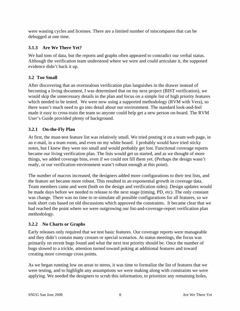
A similar problem exists when no measure source is specified. The corresponding value is left blank but no warning is issued. The keyword blank can be used to indicate that this omission is intentional, but without a warning, it is easy to overlook a missing measure source. Another example of some useful annotation statistics would be the date that the annotation was executed, and perhaps the latest date of the metric file being used, and a path to it. Beware! Warnings don’t go to stderr. Therefore, they won’t be seen on your display if you execute hvp from inside a script…. unless you redirect stdout and capture the messages. 5.8.5 Managing Feature/Sub-Feature Descriptions
I like meaningful descriptions in the feature and sub-feature columns. However, sometimes it can make the plan too long. Attention spans don’t seem to last beyond a page or two of scrolling through a spreadsheet. I could add a skip column with the information, but that too would expand the row size unless we fixed the height and hid some of the cell contents. It would be nice to specify a short but descriptive feature “name” but have an optional hover bubble. Maybe this is possible through Excel, but I’m not enough of a spreadsheet expert to know if this can be done in XML. For now, I can live with putting the detail directly in the feature and sub-feature cells, or using a skip cell and hiding things if they get too long. At least I’m not restricted to a single word. 5.8.6 Filtering Metrics (vs. Filtering Based on Attributes)
Sometimes I like to select a subset of the bins in a sample for a reduced metric during an early phase, or when there is limited time to re-simulate everything. I would like more control over defining filters for coverage metrics. For example, if the path to each bin is the same except for the last component, I’d like to be allowed to specify the sample path once per feature, then list the bins along with complex expressions (&&, ||, etc). If I am looking for an &&, I deal with this limitation by listing all bins including their full path (see Figure 7, cell H8 where I am limiting the memory types to the two highest priority configurations). If I need an || situation, then I can list the bins and reduce the goal based on the number of bins specified. (e.g. If I only need to hit one of 4 bins, I’d list all 4 and make the goal 25%). 5.9 Our Biggest Whines (High Priority Wish List)
If the Synopsys Genie granted me three VMM Planner wishes, here’s what I’d ask for… 5.9.1 Auto-bin Cross Filtering
By far, the biggest limitation is the inability to filter entries from auto-bin crosses. We have many crosses that include memory and BIO configurations. The complete list of configurations is often prohibitive. If we’re only interested in a few select memory configurations, we can’t extract only those from the crosses if they are not named samples. I realize we can’t add new samples to a cross in a post-process mode (saving enough information to the coverage database to do this would not be practical), but the information should be available and therefore allow a mechanism to filter auto-bin crosses. Our only solution is to go back and create reduced samples and new crosses with those reduced samples. That’s unacceptable!

SNUG San Jose 2008 Are We There Yet 24
5.9.2 Expandable/Collapsible Hierarchical View
The annotated results are all in one column. This makes it difficult to focus on the results for each feature for two reasons. Feature and sub-feature results are at the same level of indentation and there is no automatic mechanism to expand and collapse the feature-sub-feature rows. The first problem could be solved with support for multiple columns for annotated results (although at some point we’ll probably create so many columns that we’ll complain about the explosion in that direction). However, an expandable/collapsible hierarchy of features (not using manual hide/unhide) would make sub-plan analysis much more effective. This may be a limitation of XML. In that case, a gui may be needed after all. 5.9.3 Coverage Metric Hyperlink to URG Report
When a metric references a coverage sample that contains numerous bins, we don’t know the cause of the low score without going to the coverage report and analyzing the sample details. If the spreadsheet annotator created a link pointing to that sample in the coverage report, it would be much easier to evaluate the hole. We could include the link in the verification plan (input), but there is no anchor to point to in the plan at the level of the sample. The work-around is to petition for this enhancement. In the meantime, I need to specify each bin in the plan as an additional sub-feature. This makes the plan too “busy” and it’s a lot of extra work. 6.0 The Future (Expanded Wish List) Challenges emerged for which VMM Planner had no solution. For some, we cobbled together work-arounds. For others, we have ideas, but maybe once again, our procrastination in developing our own solution will be rewarded with enhancements to VMM Planner. In addition to putting our “whines” at the top of a wish list, here is a more pie-in-the-sky wish list… 6.1 Multiple “value” Columns Based on Priority
This request is for built-in support of multiple annotations in the same file, based on feature priorities. It is similar to our approach for filtering with respect to a Priority attribute to show results for our near-term goals. However, if we currently also want to show the results for our final goals (i.e. no filtering based on priority), we have two options. We can either generate a second annotated file, or … to see both near-term and final results in the same file, we need to duplicate the sub-plans and remove the priority column, then include those extra plans in the master plan. I would like to see a separately annotated “value” column filtered for each priority listed, as well as the results with no priority filter applied. When designs change, we remove existing coverage and start from scratch. How many times have you heard “It’s only a timing change.” and yet it introduces a bug into a previously tested feature. What if there isn’t time to run enough regressions to regenerate 100% coverage? In this case, a built-in priority-based set of annotations would be very useful. This feature would allow us to evaluate the results based on different priorities, all from a single worksheet. 6.2 Custom Views
When the plan gets so long that we need to scroll for many pages, we lose sight of the overall picture. It would be nice if we could automatically collapse and expand sections based on criteria

SNUG San Jose 2008 Are We There Yet 25
like sub-feature, coverage result (i.e. show holes, hide 100% coverage), “skip” fields, etc. This can be done manually using hide/unhide, but a more automated mechanism would be less tedious. The same is true for dealing with an excessive number of columns, especially if we track multiple values based on priority. 6.3 Temporal Hierarchical Verification Plan
Just because we get rid of coverage data when the design has changed, it doesn’t mean that we don’t care about the old information. We do eventually need to regenerate coverage to hit 100%, but it would be comforting to have previous results handy to show that we have tested various features at some point. Old reports could be saved, but how do you line up the old values with the new values to see how they intersect? We could save the old merged data in an archive and merge the old and new data in a third merged location to annotate with the old/new together. But that doesn’t show the difference between old and new coverage. We could annotate once with the old data, comment the column, and then re-annotate in an adjacent column with the new data. Once the old coverage results are captured as a comment column, it might be safe to discard the old merged data. A more automated solution would be better. While you’re collecting results over time, how about providing the ability to graph our coverage and other metric results to display the trends? 6.4 Regression Data Management
Managing regressions for multiple BIST families can be a data management nightmare. Merging the coverage data, annotating the plans, knowing what can be deleted and what should be saved… It takes keen concentration, or a script. Each regression targets a specific set of features for a particular BIST, or it might target the interaction of BISTs in a single regression (i.e. master plan goals). Our verification environments are object-oriented and if an instance is not needed in a simulation, it is not created. One by-product of this is that coverage groups are included on an as-needed basis. So, a regression targeting BIST family “A” will only have coverage data for that family. The coverage report is more useful if regression results are only merged within their targeted family. When we annotate our master verification plan, a coverage database merged across all BIST regressions makes more sense since we can now look at the plan closure from different perspectives (i.e. for each individual BIST family). By conforming to a fixed directory naming convention and structure, it wasn’t overly complex to create a script to manage merging the coverage data into appropriate “HVP” repositories. Scripting the annotation of individual plans or the master plan was also basic, and it eliminated the need to remember all the options and paths. In addition, scripting allows us to add information such as annotation dates, design baseline, e-mail notices about the availability of an update report, etc. These all seem like tasks that would be fairly common, so an integrated management tool should have broad appeal – if it is customizable.

SNUG San Jose 2008 Are We There Yet 26
7.0 Conclusions and Recommendations VMM Planner is off to a good start. Despite its Beta status and the deficiencies that I have noted, I plan to incorporate it into our verification flow. There is immediate value-add for Vera users or those who use System Verilog with VCS – even without VMM. The URG html coverage report is useful by itself, but by using VMM Planner’s Spreadsheet Annotator to link the coverage data and other metrics to an active verification plan, we can spend less time wading through coverage reports to answer, “Are we there yet?”, and spend more time finding bugs! 8.0 Acknowledgements Special thanks goes to Dwight Eddy, the Synopsys Genie, who goes out of his way to get my wish list granted. His all-around excellent AE support makes me feel like I am his only customer, even though I know I’m not! The responsiveness of the R&D team is also recognized and greatly appreciated. Thank you to Shankar Hemmady, of Synopsys, for his contagious enthusiasm for writing and presenting. I am grateful to Ron Goodstein, my reviewer, for his helpful suggestions and gentle prodding when I have missed checkpoint deadlines. Last, but not least, I could not have accomplished the work and writing without the support of my husband, Randy Pratt. In addition, his outstanding editing skills have saved the reader from many confusing typos and GUM errors (grammar, usage, and mechanics).