
Architecture-Level Support for Software Component Deployment in Resource Constrained...
15
Architecture-Level Support for Software Component Deployment in Resource Constrained Environments Marija Mikic-Rakic and Nenad Medvidovic Computer Science Department University of Southern California Los Angeles, CA 90089-0781 {marija,neno}@usc.edu Abstract. Software deployment comprises activities for installing or updating an already implemented software system. These activities include (1) deployment of a system onto a new host, (2) component upgrade in an existing system, (3) static analysis of the proposed system configuration, and (4) dynamic analysis of the con- figuration after the deployment. In this paper, we describe an approach that supports all four of these activities. The approach is specifically intended to support software deployment onto networks of distributed, mobile, highly resource constrained devices. Our approach is based on the principles of software architectures. In partic- ular, we leverage our lightweight architectural implementation infrastructure to natively support deployment in resource constrained environments. Keywords. Software deployment, software architecture, architectural style, soft- ware connector, multi-versioning, Prism 1 Introduction Software deployment involves the activities needed for installing or updating a soft- ware system, after the software has been developed and made available for release. Software systems of today often have complex architectures that are characterized by large numbers of potentially pre-fabricated (“off-the-shelf”) components. Over a long lifespan, these systems are likely to have many installed versions and experience numerous and frequent updates. The components that comprise these systems are more commonly being developed and released independently by third-party organizations (i.e., vendors). The vendors of components are themselves usually distributed, hetero- geneous, and their locations may change over time. Due to the time-to-market pres- sures, component vendors frequently release new versions that need to be deployed to large numbers of sites. However, the vendors usually have no control over a majority of the systems in which their deployed components reside. Moreover, multiple ver- sions of such systems (referred to as target systems below) are likely to exist in various locations simultaneously. For these reasons, human-operated deployment becomes impossible, and support for automated software deployment becomes critical. This picture has become even more complex with the recent emergence of inexpensive, small, heterogeneous, resource-constrained, highly distributed, and mobile computing platforms that demand highly efficient software deployment solutions. If considered from the perspective of the effects of deployment on the target sys- tem, software deployment deals with at least four problems. These problems are inde- pendent of the application domain, or nature and configuration of hardware platforms on which the software is to be deployed. The four problems are: 1. initial deployment of a system onto a new host (or set of hosts); 2. deployment of a new version of a component to an existing target system; 3. static analysis, prior to the deployment, of the likely effects of the desired modifica- tions on the target system; and 4. dynamic analysis, after the deployment, of the effects of the performed modifications on the running target system.
Transcript of Architecture-Level Support for Software Component Deployment in Resource Constrained...

Architecture-Level Support for Software ComponentDeployment in Resource Constrained Environments
Marija Mikic-Rakic and Nenad MedvidovicComputer Science Department
University of Southern CaliforniaLos Angeles, CA 90089-0781
{marija,neno}@usc.edu
Abstract. Software deployment comprises activities for installing or updating analready implemented software system. These activities include (1) deployment of asystem onto a new host, (2) component upgrade in an existing system, (3) staticanalysis of the proposed system configuration, and (4) dynamic analysis of the con-figuration after the deployment. In this paper, we describe an approach that supportsall four of these activities. The approach is specifically intended to support softwaredeployment onto networks of distributed, mobile, highly resource constraineddevices. Our approach is based on the principles of software architectures. In partic-ular, we leverage our lightweight architectural implementation infrastructure tonatively support deployment in resource constrained environments.
Keywords. Software deployment, software architecture, architectural style, soft-ware connector, multi-versioning, Prism
1 IntroductionSoftware deployment involves the activities needed for installing or updating a soft-ware system, after the software has been developed and made available for release.Software systems of today often have complex architectures that are characterized bylarge numbers of potentially pre-fabricated (“off-the-shelf”) components. Over a longlifespan, these systems are likely to have many installed versions and experiencenumerous and frequent updates. The components that comprise these systems are morecommonly being developed and released independently by third-party organizations(i.e., vendors). The vendors of components are themselves usually distributed, hetero-geneous, and their locations may change over time. Due to the time-to-market pres-sures, component vendors frequently release new versions that need to be deployed tolarge numbers of sites. However, the vendors usually have no control over a majorityof the systems in which their deployed components reside. Moreover, multiple ver-sions of such systems (referred to as target systems below) are likely to exist in variouslocations simultaneously. For these reasons, human-operated deployment becomesimpossible, and support for automated software deployment becomes critical. Thispicture has become even more complex with the recent emergence of inexpensive,small, heterogeneous, resource-constrained, highly distributed, and mobile computingplatforms that demand highly efficient software deployment solutions.
If considered from the perspective of the effects of deployment on the target sys-tem, software deployment deals with at least four problems. These problems are inde-pendent of the application domain, or nature and configuration of hardware platformson which the software is to be deployed. The four problems are:1. initial deployment of a system onto a new host (or set of hosts);2. deployment of a new version of a component to an existing target system;3. static analysis, prior to the deployment, of the likely effects of the desired modifica-
tions on the target system; and4. dynamic analysis, after the deployment, of the effects of the performed modifications
on the running target system.

Several existing approaches have been aimed at providing support for one or moreof these four activities. Typically, software deployment has been accomplished vialarge-scale “patches” that replace an entire application or set of applications (e.g., newversion of MS Word or MS Office). These patches do not provide control over thedeployment process beyond the selection of optional features available for a givenapplication (e.g., optional installation of MS Equation Editor in MS Office). Someexisting approaches (e.g., [5]), have addressed this problem by providing support fordeployment at a finer-grain component level. However, these approaches have typi-cally taken a configuration management perspective on the deployment problem,tracking dependencies among versions of implemented modules, and rarely taking intoaccount system architectures, their evolution over time due to the frequent componentupgrades, or the relationship of the deployed multiple versions of a given system tothat system’s architecture. Furthermore, these approaches have often required sophisti-cated deployment support (e.g., deployment agents [5]) that uses its own set of facili-ties, provided separately from the application’s implementation infrastructure, therebyintroducing additional overhead to the target host. For these reasons, these approachesare usually not applicable in an emerging class of light-weight, resource constrained,highly distributed, and mobile computational environments.
In this paper, we propose an approach that attempts to overcome the shortcomingsof previous work and address all four deployment problems discussed above. Ourapproach directly leverages a software system’s architecture in enabling deployment.Specifically, we have been able to adapt our existing architectural implementationinfrastructure to natively and inexpensively support deployment, both at system con-struction-time and run-time. Our solution is light weight and is applicable in a highlydistributed, mobile, resource constrained, possibly embedded environment. A keyaspect of the approach is its support for intelligent, dynamic upgrades of componentversions. We have provided a graphical software deployment environment, and haveevaluated our approach on a series of applications distributed across a variety of desk-top, lap-top, and hand-held devices.
The rest of the paper is organized as follows. Section 2 briefly describes an exam-ple application used to illustrate the concepts throughout the paper. Section 3 summa-rizes the architectural style used as the basis of this work and its accompanyinginfrastructure for implementing, deploying, migrating, and dynamically reconfiguringapplications. Section 4 discusses our approach to supporting component deployment,while Section 5 describes in more detail a technique for supporting upgrades of com-ponent versions. The paper concludes with overviews of related and future work.
2 Example ApplicationTo illustrate our approach, we use an application for distributed, “on the fly” deploy-ment of personnel, intended to deal with situations such as natural disasters, militarycrises, and search-and-rescue efforts. The specific instance of this application depictedin Figure 1 addresses military Troops Deployment and battle Simulations (TDS). Acomputer at Headquarters gathers all information from the field and displays the com-plete current battlefield status: the locations of friendly and enemy troops, as well asobstacles such as mine fields. The Headquarters computer is networked via a securelink to a set of hand-held devices used by officers in the field. The configuration in Fig-ure 1 shows three Commanders and a General; two Commanders use Palm Pilot Vx

devices, while the third uses a Compaq iPAQ; the General uses a Palm Pilot VIIx. TheCommanders are capable of viewing their own quadrant of the battlefield and deploy-ing friendly troops within that quadrant to counter enemy deployments. The Generalsees a summarized view of the entire battlefield (shown); additionally, the General iscapable of seeing detailed views of each quadrant. Based on the global battlefield situ-ation, the General can issue direct troop deployment orders to individual Commandersor request transfers of troops among the Commanders. The General can also requestfor deployment strategy suggestions from Headquarters, based on current positions ofenemy troops, mines, and the number of friendly troops at disposal. Finally, the Gen-eral can issue a “fight” command, resulting in a battle simulation that incrementallydetermines the likely winner given a configuration of troops and obstacles.
Figure 1. TDS applicationdistributed across multiple
devices.
HEADQUARTERS
COMMANDER 3
COMMANDER 1 COMMANDER 2
GENERAL
Figure 2. Architecture ofthe TDS application,
displayed in the Prismdeployment
environment. Theunlabeled circles
connecting componentsacross the hand-held
devices represent peerconnectors.

The TDS application provides an effective platform for illustrating our ideas. It hasbeen designed, implemented, and deployed using the approach described in this paper.In the instance of TDS shown in Figures 1 and 2, sixteen software componentsdeployed across the five devices interact via fifteen software connectors.
3 Architectural Basis for Software DeploymentWe are using a software architectural approach as the basis of our support for deploy-ment. Software architectures provide high-level abstractions for representing struc-ture, behavior, and key properties of a software system [17]. They are described interms of components, connectors, and configurations. Architectural componentsdescribe the computations and state of a system; connectors describe the rules andmechanisms of interaction among the components; finally, configurations definetopologies of components and connectors. Software architectural styles involve identi-fying the types of elements from which systems are built, the characteristics of theseelements, the allowed interactions among the elements, and the patterns that guidetheir composition [14]. The specific architectural style upon which we are relying inthis work is PitM [9].
3.1 Architectural StyleThe PitM style is targeted at heterogeneous, highly distributed, highly mobile,resource constrained, possibly embedded systems. In formulating the PitM style, wehave leveraged our extensive experience with the C2 architectural style, which isintended to support highly distributed applications in the graphical user interface(GUI) domain [18]. PitM-style components maintain state and perform application-specific computation. The components may not assume a shared address space, butinstead interact with other components solely by exchanging messages via their threecommunication ports (named top, bottom, and side). Connectors in the PitM stylemediate the interaction among components by controlling the distribution of all mes-sages. A message consists of a name and a set of typed parameters.
A message in the PitM style is either a request for a component to perform an oper-ation, a notification that a given component has performed an operation and/or changedits state, or a peer message used in direct (peer-to-peer) communication between com-ponents. Request messages are sent through the top port, notifications through the bot-tom port, and peer messages through the side port of a component. The distinctionbetween requests and notifications ensures PitM’s principle of substrate independence,which mandates that a component in an architecture may have no knowledge of ordependencies on components below it. In order to preserve this property, two PitMcomponents may not engage in interaction via peer messages if there exists a verticaltopological relationship between them. For example, DataRepository on the PC andG_ScenarioEditor on the Palm-1 in Figure 2 may not exchange peer messages sinceone component is above the other; on the other hand, no vertical topological relation-ship exists between C_iPAQ_AvailableTroops on the iPAQ and G_AvailableTroops onthe Palm-1, meaning that they may communicate via peer messages.
3.2 Software ConnectorsA PitM-style connector does not have an interface at declaration-time; instead, as com-ponents are attached to it, the connector’s interface is dynamically updated to reflectthe interfaces of the components that will communicate through the connector. This

“polymorphic” property of connectors is the key enabler of our support for deploy-ment, and run-time reconfiguration. PitM distinguishes between two types of connec-tors. Horizontal connectors enable the request-notification type of communicationamong components through their top and bottom ports, while peer connectors enablepeer-to-peer communication among components through their side ports. The PitMstyle does not allow a peer and a horizontal connector to exchange messages; thiswould, in effect, convert peer messages into requests/notifications, and vice versa.
The PitM style directly supports connectors that span device boundaries. Such con-nectors, called border connectors, enable the interactions of components residing onone device with components on other devices (e.g., BottomBorderConnector on thePC in Figure 2). A border connector marshals and unmarshals data, code, and architec-tural models, and dispatches and receives messages across the network. It may alsoperform data compression for efficiency and encryption for security. A Border Con-nector may facilitate communication via requests and notifications (horizontal borderconnector) or via peer messages (peer border connector).
3.3 Architectural Modeling and AnalysisPitM supports architectures at two levels: application-level and meta-level. The role ofcomponents at the PitM meta-level is to observe and/or facilitate different aspects ofthe deployment, execution, dynamic evolution, and mobility of application-level com-ponents. Both application-level and meta-level components obey the rules of the style.They execute side-by-side: meta-level components are aware of application-level com-ponents and may initiate interactions with them, but not vice versa.
In support of this two-level architecture, PitM currently distinguishes among threetypes of messages. ApplicationData messages are used by application-level compo-nents to communicate during execution. The other two message types are used byPitM meta-level components: ComponentContent messages contain mobile code andaccompanying information (e.g., the location of a migrant component in the destina-tion configuration), while ArchitecturalModel messages carry information needed toperform architecture-level analyses of prospective PitM configurations (e.g., duringdeployment).
We have extensively used special-purpose components, called Admin Components,whose task is to exchange ComponentContent messages and facilitate the deploymentand mobility of application-level components across devices. Another meta-level com-ponent is the Continuous Analysis component, which leverages ArchitecturalModelmessages for analyzing the (partial) architectural models during the application’s exe-cution, assessing the validity of proposed run-time architectural changes, and possiblydisallowing the changes.
In support of this task, we have recently added architecture description language(ADL) support to PitM. We have extended our existing ADL (C2SADEL [10]) andtool support (DRADEL [10]) with a set of new capabilities for modeling and analyzingPitM-style architectures. Specifically, the Continuous Analysis component is builtusing a subset of DRADEL to assess the proposed architectural (re)configurations.That assessment is carried out by matching the interfaces and behaviors (expressed viacomponent invariants and operation pre- and post-conditions) of the interacting com-ponents [10].

3.4 Architectural ImplementationPitM provides stylistic guidelines forcomposing large, distributed, mobilesystems. For these guidelines to beuseful in a development setting, theymust be accompanied by support fortheir implementation. To this end,we have developed a light-weightarchitecture implementation infra-structure. The infrastructure com-prises an extensible framework ofimplementation-level modules rep-resenting the key elements of thestyle (e.g., architectures, compo-nents, connectors, messages) andtheir characteristics (e.g., a messagehas a name and a set of parameters).An application architecture is then constructed by extending the appropriate classes inthe framework with application-specific detail. The framework has been implementedin several programming languages: Java JVM and KVM [19], C++ and EmbeddedVisual C++ (EVC++), and Python.
A subset of the PitM framework’s UML class diagram is shown in Figure 3. Theclasses shown are those of interest to the user of the framework (i.e., the applicationdeveloper). Multiple components and connectors in an architecture may run in a singlethread of control (Component and Connector classes), or they may have their ownthreads (ComponentThread and ConnectorThread). The Architecture class records theconfiguration of its constituent components and connectors, and provides meta-levelfacilities for their addition, removal, replacement, and reconnection, possibly at systemrun-time. A distributed application, such as TDS, is implemented as a set of interactingArchitecture objects as shown in Figure 4.
The first step a developer (or tool generating an implementation from an architec-tural description [10]) takes is to subclass from the Component or ComponentThreadframework classes for all components in the architecture and to implement the applica-tion-specific functionality for them. The next step is to instantiate the Architecture
Figure 3. Class design view of the PitM implementationframework.
ComponentThreadConnectorThread
ArchitectureAdapter
Notification Request
Message
Serializable
IScaffold
ConnectorIArchitecture
ArchitectureEventConstants
IComponent
Peer
Component
IConnector #top
#bottom
#side
AdminComponent
Architecture
Brick
#scaffold
Address topId
bottomId
sideId
Figure 4. Layered constructionof an application using the PitMimplementation framework. Theapplication is distributed acrossfive devices, each of which isrunning the framework. Meta-
level components (highlighted inthe figure) may control the
execution of application-levelcomponents via PitM messages
or via pointers to the localArchitecture object (shown in
the subarchitecture on the PC).

classes for each device and define the needed instances of thus created components, aswell as the connectors selected from the connector library. Finally, attaching compo-nents and connectors into a configuration is achieved by using the weld and peerWeldmethods of the Architecture class. At any point, the developer may add meta-levelcomponents, which may be welded to specific application-level connectors and thusexercise control over a particular portion of the Architecture (e.g., Admin Componentin Figure 4). Alternatively, meta-level components may remain unwelded and mayinstead exercise control over the entire Architecture object directly (e.g., ContinuousAnalysis component in Figure 4).
4 System DeploymentOur support for deployment addresses problems 1 and 3 stated in the Introduction (ini-tial system deployment and static analysis prior to deployment) by directly leveragingthe PitM implementation infrastructure. We have developed a custom solution fordeploying applications instead of trying to reuse existing capabilities (e.g., [5])because of the facilities provided by the PitM style (ComponentContent messages,Admin Components, meta-level architecture) and the light weight of the PitM imple-mentation framework, which is critical for small, resource constrained devices (e.g.,Palm Pilot, which has 256KB of dynamic heap memory). We use the same infrastruc-ture for the initial deployment of a system onto a new host (or set of hosts) and fordeploying a new version of a component to an existing target system.
4.1 Basic RequirementsIn order to deploy the desired architecture on a set of target hosts, we assume that askeleton (meta-level) configuration is preloaded on each host. The configuration con-sists of the PitM implementation framework, with an instantiated Architecture objectthat contains a Border Connector and an Admin Component attached to the connector.The skeleton configuration is extremely lightweight. For example, in our Java imple-mentation, the skeleton uses as little as 6.6KB of dynamic memory. Since the PitMframework, Architecture object, and Border Connector are also used at the applicationlevel, the actual memory overhead of our basic deployment support (i.e., the AdminComponent) is only around 180B.
The Admin Component on each device contains a pointer to its Architecture objectand is thus able to effect run-time changes to its local subsystem’s architecture: instan-tiation, addition, removal, connection, and disconnection of components and connec-tors. Admin Components are able to send and receive from any device to which theyare connected the meta-level ComponentContent messages through Border Connec-tors. Each Admin Component can request the components that are to be deployed in itssubsystem’s architecture. Finally, each Admin Component has the knowledge of the setof components that are available in the local configuration via a pointer to the Archi-tecture object.
4.2 Deployment ProcessThe current configuration of a system describes its current topology. The desired con-figuration represents a configuration that needs to be deployed. If there is a differencebetween the current and desired configurations, the deployment process will be initi-ated. The information about the current and desired configurations can either be storedon a single host (centralized ownership) or each subsystem may have the knowledge of

its current and desired configurations (dis-tributed ownership). In the first scenario,the Admin Component on the host storingthe descriptions of configurations will ini-tiate the deployment on all hosts. In thesecond scenario, each Admin Componentwill initiate the deployment on its localhost.
In order to support centralized owner-ship of the application’s architecture, theskeleton configuration on the central hostshould also contain a Continuous Analysiscomponent. The centralized ContinuousAnalysis component has the knowledge ofthe current and desired configurations forall subsystems. Figure 5 shows the partialdescription of the TDS application config-uration used by the central ContinuousAnalysis component.
Distributed ownershipof the application’s archi-tecture requires that theskeleton configuration oneach host contain a Contin-uous Analysis component(attached to the local Bor-der Connector), which isaware of its subsystemconfiguration. Each Con-tinuous Analysis compo-nent is capable ofanalyzing the validity ofarchitectural configurations either by performing the analysis locally or by requestingthe analysis of a given configuration remotely (e.g., on a more capacious host that canperform such analysis). Additionally, the Continuous Analysis component is capable ofstoring the desired (but not yet deployed) local configuration.
Table 1 and Figures 7 and 8 describe the deployment process in the Java version ofour implementation and deployment framework for both the cases of centralized anddistributed ownership of the application’s architecture.
4.3 Deployment EnvironmentWe have integrated and extended the MS Visio tool to develop Prism, the PitM archi-tectural modeling and deployment environment (see Figure 2). Prism contains severaltoolboxes (shown on the left side of Figure 2). The top toolbox enables an architect tospecify a configuration of hardware devices by dragging their icons onto the canvasand connecting them. Prism currently assumes that the available devices and theirlocations are known; we are extending Prism with support for automated discovery of
architecture TDS is {component_types {component PC_StrategyAnalyzer is extern {
C:\spec\PC_StrategyAnalyzer.pitm;}...component C_AvailableTroops is extern {
C:\spec\C_AvailableTroops.pitm;}...}}
architectural_topology {component_instances {
pcStratAnalyzer : PC_StrategyAnalyzer;pcDataRepository : PC_DataRepository;cAvailableTroops: C_AvailableTroops;cAvailableTroops1: C_AvailableTroops;}
connector_instances {BottomBorderConn : RegularConn;}
peer_connector_instances {PeerCon : PeerConn;}connections {
connector BottomBorderConn {top pcStratAnalyzer;bottom pcDataRepository;}}
peer_connections{peer_connector PeerCon {side cAvailableTroops, cAvailableTroops1;}
}}
Figure 5. Partial architectural specification of theTDS application in the PitM ADL. Individual
components are specified in separate files denotedby the extern keyword.
add(DataRepository: source PC): PCadd(DeploymentStrategiesRepository: source PC): PCadd(DataConnector: source none): PCadd(C_IPAQAvailableTroops: source local): iPAQadd(C_IPAQScenarioEditor: source PC): iPAQadd(SaConnector: source none): iPAQweld(DataRepository,DataConnector): PCweld(DeploymentStrategiesRepository,DataConnector): PCweld(C_IPAQAvailableTroops,SaConnector): iPAQweld(TopBorderConnector,C_IPAQAvailableTroops): iPAQweld(SaConnector,C_IPAQScenarioEditor): iPAQpeerWeld(G_AvailableTroops,SideBorderConnector):Palm-1
Figure 6. Partial description of the configuration created by Prism forthe TDS application. Component source and destination devices areshown. Sources are denoted as “none” in the case of connectors that
use the base implementation (asynchronous message broadcast)provided by the PitM framework.
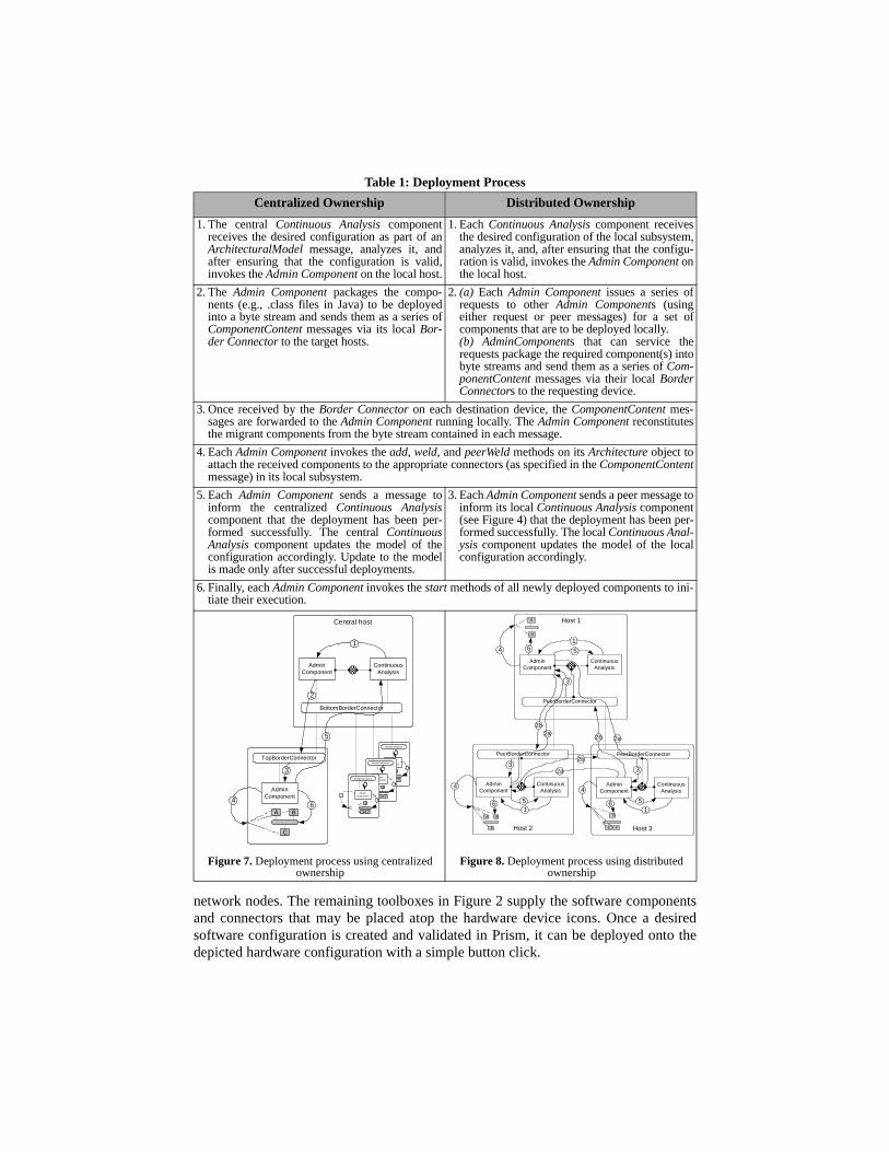
network nodes. The remaining toolboxes in Figure 2 supply the software componentsand connectors that may be placed atop the hardware device icons. Once a desiredsoftware configuration is created and validated in Prism, it can be deployed onto thedepicted hardware configuration with a simple button click.
Table 1: Deployment Process
Centralized Ownership Distributed Ownership
1. The central Continuous Analysis componentreceives the desired configuration as part of anArchitecturalModel message, analyzes it, andafter ensuring that the configuration is valid,invokes the Admin Component on the local host.
1. Each Continuous Analysis component receivesthe desired configuration of the local subsystem,analyzes it, and, after ensuring that the configu-ration is valid, invokes the Admin Component onthe local host.
2. The Admin Component packages the compo-nents (e.g., .class files in Java) to be deployedinto a byte stream and sends them as a series ofComponentContent messages via its local Bor-der Connector to the target hosts.
2. (a) Each Admin Component issues a series ofrequests to other Admin Components (usingeither request or peer messages) for a set ofcomponents that are to be deployed locally.(b) AdminComponents that can service therequests package the required component(s) intobyte streams and send them as a series of Com-ponentContent messages via their local BorderConnectors to the requesting device.
3. Once received by the Border Connector on each destination device, the ComponentContent mes-sages are forwarded to the Admin Component running locally. The Admin Component reconstitutesthe migrant components from the byte stream contained in each message.
4. Each Admin Component invokes the add, weld, and peerWeld methods on its Architecture object toattach the received components to the appropriate connectors (as specified in the ComponentContentmessage) in its local subsystem.
5. Each Admin Component sends a message toinform the centralized Continuous Analysiscomponent that the deployment has been per-formed successfully. The central ContinuousAnalysis component updates the model of theconfiguration accordingly. Update to the modelis made only after successful deployments.
3. Each Admin Component sends a peer message toinform its local Continuous Analysis component(see Figure 4) that the deployment has been per-formed successfully. The local Continuous Anal-ysis component updates the model of the localconfiguration accordingly.
6. Finally, each Admin Component invokes the start methods of all newly deployed components to ini-tiate their execution.
Figure 7. Deployment process using centralizedownership
BorderConnector
AdminComponent
3
D
E F
4
6
Central host
AdminComponent
ContinuousAnalysis
BottomBorderConnector
1
TopBorderConnector
AdminComponent
2
3
5
A
C
B6
BorderConnector
AdminComponent
3
D
E F
4
6
BorderConnector
AdminComponent
3
D
E F
4
64
Figure 8. Deployment process using distributedownership
Host 1
AdminComponent
ContinuousAnalysis
PeerBorderConnector
Host 2
PeerBorderConnector
AdminComponent
ContinuousAnalysis
1
1
Host 3
PeerBorderConnector
AdminComponent
ContinuousAnalysis
1
4 4
A
C
B D
E F
G
H
4 5
5 5
3
3
3
6 6
6
2a
2a
2a
2b
2b
2b

Prism supports deployment using centralized ownership of the application’s archi-tecture. Recall that this is not the case with our implementation framework, which alsosupports decentralized ownership as discussed in Section 4.2. Our current implementa-tion assumes that the locations of the compiled code for all the needed components andconnectors are known, and specified inside Prism. Each software component in thetoolboxes is associated with its compiled code location and its architectural descrip-tion. Once the desired configuration is created, its validity can be assured automati-cally: Prism generates the appropriate architectural description in the PitM ADL (e.g.,recall Figure 5) and invokes its internal Continuous Analysis component to ensure thatthe description is valid. Once the user requests that the architecture be deployed, Prismgenerates a series of deployment commands as shown in Figure 6. These commandsare used as invocations to the skeleton configuration on the device on which Prismresides. The local Admin Component initiates the deployment process on all hosts asspecified in the left column of Table 1.
5 Component UpgradePrism and its integrated analysis capabilities provide assurance that the specified con-figuration of components and connectors is valid according to the architectural specifi-cation. However, implemented components may not preserve all the properties andrelationships established at the architectural level (e.g., due to accidental codingerrors) [11]. This section describes a run-time approach to supporting reliable upgradesof existing component versions [2,15] and reliable deployment of new components,addressing problems 2 and 4 stated in the Introduction.
When upgrading a component, vendors try to maintain the old component version’skey properties (e.g., granularity, implementation language, and interaction paradigm),while enhancing its functionality (by adding new features) and/or reliability (by fixingknown bugs). However, component upgrades raise a set of questions, includingwhether the new version correctly preserves the functionality carried over from the oldversion, whether the new version introduces new errors, and whether there is any per-formance discrepancy between the old and new versions. Depending on the kinds ofproblems a new component version introduces and the remedies it provides for the oldversion’s problems, this scenario can force a user to make some interesting choices:• deploy the new version of the component to replace the old version;• retain the old version; or• deploy both the old and new versions of the component in the system.Prior to making one of these choices, the user must somehow assess the new compo-nent in the context of the environment within which the old component is running, and,once the choice is made, the running system needs to be updated.
5.1 Multi-Versioning ConnectorsWe illustrate our approach in the context of the example application described in Sec-tion 2. Figure 9 shows the partial architectural configuration of the TDS application. Inthis configuration, a Strategy Analyzer component provides several operations as illus-trated in Figure 10. Let us assume that, after this application is deployed, we obtaintwo new versions of Strategy Analyzer that are claimed to be improvements over theold version. We would like to assess both new versions before deciding which one todeploy in our system.
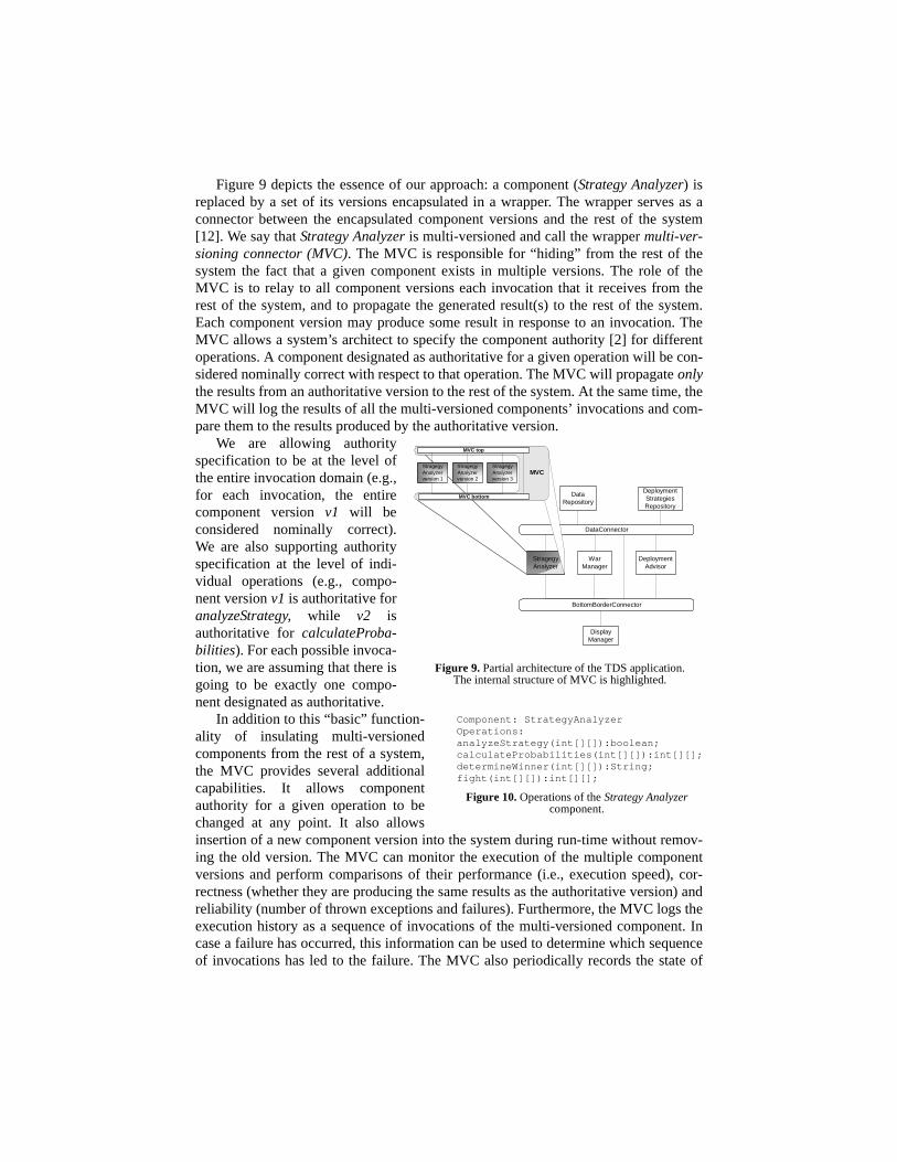
Figure 9 depicts the essence of our approach: a component (Strategy Analyzer) isreplaced by a set of its versions encapsulated in a wrapper. The wrapper serves as aconnector between the encapsulated component versions and the rest of the system[12]. We say that Strategy Analyzer is multi-versioned and call the wrapper multi-ver-sioning connector (MVC). The MVC is responsible for “hiding” from the rest of thesystem the fact that a given component exists in multiple versions. The role of theMVC is to relay to all component versions each invocation that it receives from therest of the system, and to propagate the generated result(s) to the rest of the system.Each component version may produce some result in response to an invocation. TheMVC allows a system’s architect to specify the component authority [2] for differentoperations. A component designated as authoritative for a given operation will be con-sidered nominally correct with respect to that operation. The MVC will propagate onlythe results from an authoritative version to the rest of the system. At the same time, theMVC will log the results of all the multi-versioned components’ invocations and com-pare them to the results produced by the authoritative version.
We are allowing authorityspecification to be at the level ofthe entire invocation domain (e.g.,for each invocation, the entirecomponent version v1 will beconsidered nominally correct).We are also supporting authorityspecification at the level of indi-vidual operations (e.g., compo-nent version v1 is authoritative foranalyzeStrategy, while v2 isauthoritative for calculateProba-bilities). For each possible invoca-tion, we are assuming that there isgoing to be exactly one compo-nent designated as authoritative.
In addition to this “basic” function-ality of insulating multi-versionedcomponents from the rest of a system,the MVC provides several additionalcapabilities. It allows componentauthority for a given operation to bechanged at any point. It also allowsinsertion of a new component version into the system during run-time without remov-ing the old version. The MVC can monitor the execution of the multiple componentversions and perform comparisons of their performance (i.e., execution speed), cor-rectness (whether they are producing the same results as the authoritative version) andreliability (number of thrown exceptions and failures). Furthermore, the MVC logs theexecution history as a sequence of invocations of the multi-versioned component. Incase a failure has occurred, this information can be used to determine which sequenceof invocations has led to the failure. The MVC also periodically records the state of
Figure 9. Partial architecture of the TDS application.The internal structure of MVC is highlighted.
DataRepository
DisplayManager
WarManager
DeploymentStrategiesRepository
DeploymentAdvisor
StragegyAnalyzer
BottomBorderConnector
DataConnector
StragegyAnalyzerversion 1
StragegyAnalyzerversion 2
StragegyAnalyzerversion 3
MVC top
MVC bottom
MVC
Component: StrategyAnalyzerOperations:analyzeStrategy(int[][]):boolean;calculateProbabilities(int[][]):int[][];determineWinner(int[][]):String;fight(int[][]):int[][];
Figure 10. Operations of the Strategy Analyzercomponent.

each component version. The execution history and state “snapshots” can be used toroll back the execution of a multi-versioned component to any point in its past [15].
MVC’s monitoring mechanism (logging of component invocations, comparisons oftheir results, and component state “snapshots”) can help a user decide among replacingthe old component version with the new, retaining the old version, and simultaneouslydeploying multiple versions of a single component in the system. In the first two cases,the MVC can be removed from the system to reduce the overhead introduced by itsinsertion. In the last case, the MVC will be retained and used to “simulate” the func-tionality of a single conceptual component. In that case, the monitoring can be disabledto minimize the overhead.
To date, we have primarily focused on the use of our approach in the case of com-ponent upgrades. However, the same infrastructure can be used when an entirely newcomponent needs to be reliably deployed into a system. The wrapped component canbe deployed at the desired location in the system’s architecture in the manner discussedin Section 4. The component’s behavior can then be assessed with minimal disturbanceto the rest of the system since the MVC will be configured to “trap” all the invocationsthe component tries to make. Once the new component is assessed in the context of thedeployed system and it is established that the component produces satisfactory results,the wrapper around it (i.e., the MVC) may be removed.
5.2 Implementation of MVCWe have directly leveraged PitM’s implementation infrastructure in constructing theMVC. In particular, we have implemented three special-purpose, reusable softwareconnectors, called MVC-Top, MVC-Bottom, and MVC-Side. Each connector serves asan intermediary between the multi-versioned component and the corresponding portthrough which the component is attached to the rest of the system. Depending onwhich ports are used by the multi-versioned component, one, two, or all three MVCconnectors would be required to create the wrapper. Figure 9 shows one possible wrap-ping scenario, in which the multiversioned component is communicating using the topand bottom, but not side ports. MVC-Top and MVC-Bottom connectors encapsulatemultiple versions of a component, allowing their parallel execution and monitoring.The intrinsic support of the PitM framework for dynamic addition and removal ofcomponents [9,13] is leveraged in the context of the MVC to add and remove compo-nent versions during run-time.
When a message is sent to a multi-versioned component (e.g., Strategy Analyzer inFigure 9) from any component below the MVC-Bottom or above the MVC-Top connec-tors, the corresponding connector invokes within each component version the opera-tion that is responsible for processing that message. Even though the operation isinvoked on all the installed versions, only the messages generated by the authoritativeversion are propagated by the two MVC connectors to the rest of the system. In ourexample, whenever a determineWinner request message is sent from the Display Man-ager component, MVC-Bottom will return to Display Manager only the result pro-duced by (the authoritative) version v2; the results produced by versions v1 and v3 arecompared with those of v2 and logged, but are not propagated to the rest of the system.
The GUI of our implementation of the MVC is shown in the bottom window ofFigure 11. This window is separate from an application’s UI, such as that of TDS, par-tially depicted in the top window. The MVC window shows the list of component ver-

sions in the upper left frame. The table in the upper right frame shows the currentauthority specification and the total (cumulative) execution time, in milliseconds, foreach invoked operation of a selected component version (in this case, version v1 ofStrategy Analyzer).
The table in themiddle frame dis-plays the executionstatistics for theselected compo-nent version. Foreach operation, thetable shows thenumber of timesthe operation hasbeen invoked, theaverage executiontime for that opera-tion (-1 if the oper-ation is notimplemented bythe componentversion), and thenumber of timesthe operation pro-duced identicaland differentresults in comparison to the authoritative version. The table also displays the numberof times an error (an exception or a failure) occurred during the execution of the oper-ation, and whether the invoked operation is implemented by the component version.
The bottom two frames in the MVC window display the call and result logs assequences of generated messages. Using these logs, the Undo button can revert thestates of a given set of multi-versioned components to any point in the past. This capa-bility is achieved by taking “snapshots” of and storing the versions’ states at regularintervals and by logging each message sent to the multi-versioned component. Adetailed description of the undo process is given in [15].
The overhead of MVC is linearly proportional to the number of operations of themultiversioned component, and can be calculated using the following formula:
Mem(MVC)=1208+44*num_op (in bytes)where Mem(MVC) is the memory usage of a single MVC and num_op is the total num-ber of operations provided by the multi-versioned component. For example, the over-head of a single MVC for a component with 10 operations is around 1.6KB. Theoverhead of MVC’s GUI is 680KB since it uses an off-the-shelf GUI framework (JavaSwing). While this overhead is acceptable on desk-top and even some hand-held plat-forms (e.g., the iPAQ), it is too expensive for devices with significant resource con-straints (e.g., the Palm Pilot). We are currently developing a simplified version of theUI that is targeted for such, less capacious platforms.
Figure 11. MVC monitoring window(bottom) and a screenshot of the TDS
application (top).

6 Related WorkIn addition to software architectures, discussed in Section 3, this section outlines otherrelevant research. Carzaniga et. al. [1] proposed a comparison framework for softwaredeployment techniques. They identified the activities in the software deployment pro-cess and provided an extensive comparison of existing approaches based on their cov-erage of the deployment activities. Our approach has similar coverage of thedeployment process to application management systems [1]. Below, we brieflydescribe two approaches most closely related to ours.
Software Dock [5] is a system of loosely coupled, cooperating, distributed compo-nents. It supports software producers by providing a Release Dock and a Field Dock.The Release Dock acts as a repository of software system releases. The Field Docksupports a software consumer by providing an interface to the consumer’s resources,configuration, and deployed software systems. The Software Dock employs agentsthat travel from a Release Dock to a Field Dock in order to perform specific softwaredeployment tasks. A wide area event system connects Release Docks to Field Docks.The entire infrastructure of Software Dock introduces substantial overhead, and istherefore not directly applicable for the classes of applications that need to be deployedonto resource constrained devices.
Cook and Dage [2] have developed an approach to reliable software componentupgrades that is most closely related to ours. Their component upgrade framework,HERCULES, treats only individual procedures as components, allows multiple suchprocedures to be executed simultaneously, and provides a means for comparing theirexecution results. Unlike our MVC, HERCULES does not provide any support forinserting and removing component versions at system run-time, or reverting a multi-versioned component to its past execution state.
7 Conclusions and Future WorkSoftware deployment is a central activity in the software development lifecycle. Thedeployment process changes the architecture of the target systems, as well as the sys-tems’ behavior. In order to ensure the desired effects of deployment, these changesneed to be analyzed and controlled. The recent emergence of inexpensive, light-weight, resource constrained, highly distributed and mobile platforms additionallydemands highly efficient software deployment solutions.
This paper has presented an approach that addresses these issues. Our approachdirectly leverages a system’s architecture in enabling deployment. We have adaptedour existing architectural implementation infrastructure to natively support the fourdeployment activities outlined in the Introduction. Our solution is extremely light-weight and has been successfully ported to a number of desk-top and hand-held plat-forms. While our experience thus far has been very positive, a number of issues remainareas of future work.
The issue of trust is central to the deployment of PitM applications due to theirincreased distribution, heterogeneity, and (possibly wireless) communication. Webelieve that explicit, first-class software connectors may be used to effectively supportsecure deployment in the PitM setting. The connectors may be used to implement vari-ous security protocols, including authentication, authorization, encryption, certificates,and sessions [12]. To date, we have implemented an encryption module inside Border

Connectors. We plan to extend and directly apply this capability in our deploymentsupport in the near future.
Another critical issue associated with highly distributed, mobile, possibly embed-ded systems is performance [6]. Our longer term goal is to develop techniques foractively assessing PitM applications and suggesting deployment strategies that mini-mize network traffic and maximize performance and availability. This includes estima-tion of optimal component locations in a distributed configuration, estimation of whichcomponents should be deployed, and, finally, when the deployment should occur. Weintend to integrate PitM’s support for architectural self-awareness and run-time moni-toring with existing tools for system resource analysis [4] in order to enable these esti-mations.
8 References1. A. Carzaniga et. al. A Characterization Framework for Software Deployment Technologies.
Technical Report, Dept. of Computer Science, University of Colorado, 1998.2. J. E. Cook and J. A. Dage. Highly Reliable Upgrading of Components. 21st International
Conference on Software Engineering (ICSE’99), Los Angeles, CA, May 1999.3. F. DeRemer and H. Kron. Programming-in-the-Large Versus Programming-in-the-Small.
IEEE Transactions on Software Engineering, June 1976.4. P. H. Feiler and J. J. Walker. Adaptive Feedback Scheduling of Incremental and Design-To-
Time Tasks. 23rd International Conference on Software Engineering (ICSE 2001), Toronto,Canada, May 2001.
5. R. S. Hall, D. M. Heimbigner, and A. L. Wolf. A Cooperative Approach to Support SoftwareDeployment Using the Software Dock. 21st International Conference on SoftwareEngineering (ICSE’99), Los Angeles, CA, May 1999.
6. E. A. Lee. Embedded Software. Technical Memorandum UCB/ERL M001/26, UCBerkeley, CA, July 2001
7. T. Lindholm and F. Yellin. The Java Virtual Machine Specification. Addison Wesley 1999.8. N. Medvidovic, et al. Reuse of Off-the-Shelf Components in C2-Style Architectures. 19th
International Conference on Software Engineering (ICSE'97), Boston, MA, May 1997.9. N. Medvidovic and M. Mikic-Rakic. Architectural Support for Programming-in-the-Many.
Technical Report, USC-CSE-2001-506, University of Southern California, October 2001.10. N. Medvidovic, et al. A Language and Environment for Architecture-Based Software
Development and Evolution. 21st International Conference on Software Engineering(ICSE’99), Los Angeles, CA, May 1999.
11. N. Medvidovic and R. N. Taylor. A Classification and Comparison Framework for SoftwareArchitecture Description Languages. IEEE Transactions on Software Engineering, January2000.
12. N. Mehta, N. Medvidovic, and S. Phadke. Towards a Taxonomy of Software Connectors.22nd International Conference on Software Engineering (ICSE 2000), Limerick, June 2000.
13. P. Oreizy, N. Medvidovic, and R. N. Taylor. Architecture-Based Runtime SoftwareEvolution. 20th International Conference on Software Engineering (ICSE’98), Kyoto,Japan, April 1998.
14. D.E. Perry, and A.L. Wolf. Foundations for the Study of Software Architectures. ACMSIGSOFT Software Engineering Notes, October 1992.
15. M. Rakic and N. Medvidovic. Increasing the Confidence in Off-the-Shelf Components: ASoftware Connector-Based Approach. Symposium on Software Reusability, Toronto,Canada, May 2001.
16. B. Shannon, et al. Java 2 Platform, Enterprise Edition: Platform and ComponentSpecifications. Addison Wesley 2000.
17. M. Shaw, and D. Garlan. Software Architecture: Perspectives on an Emerging Discipline.Prentice Hall, 1996.
18. R.N. Taylor, N. Medvidovic, et al. A Component- and Message-Based Architectural Stylefor GUI Software. IEEE Transactions on Software Engineering, June 1996.
19. Sun Microsystems. K Virtual Machine (KVM). http://java.sun.com/products/kvm.


![SOFTARCH: TOOL SUPPORT FOR INTEGRATED SOFTWARE ...€¦ · Argo/UML [12] and Visper [13], use various kinds of structural architecture component diagrams. Most of these systems provide](https://static.fdocuments.in/doc/165x107/5f35e07c9571106c44260bcf/softarch-tool-support-for-integrated-software-argouml-12-and-visper-13.jpg)

