Arc Welding System /M2001 - ABB Ltd settings Calibrating the robot and the external axes 8 504...
72
System Settings Arc Welding System /M2001 504 874-102 Revision, 2003-09
Transcript of Arc Welding System /M2001 - ABB Ltd settings Calibrating the robot and the external axes 8 504...
System SettingsArc Welding System /M2001
504 874-102 Revision, 2003-09

The information in this document can be subject to change without prior notice and should not be regarded as an undertaking from ABB. ABB assumes no responsibility for errors that can appear in this document.
ABB is not responsible for damage incurred by the use of this document or software or hardware described in this document.
The document, or parts there of, may not be reproduced or copied without prior permission from ABB. It may neither be imparted to a third party nor otherwise used without authorisation. Infringement here of will be subject to action in accordance with applicable laws.
Further copies of this document can be obtained from ABB at current prices.
© ABB Automation Technology Products AB
Article number: 504 874-102
Date: Revision, 2003-09
ABB Automation Technology Products AB
Arc Welding & Application Equipment
S-695 82 Laxå
Sweden
System settings
CONTENTSPage
504 874-102 3
1 Safety ............................................................................................................................ 5
2 Calibrating the robot and the external axes ............................................................. 7
2.1 Manual setting of the calibration values ............................................................ 72.2 Updating the revolution counter ........................................................................ 92.3 Recalibrating the axes ........................................................................................ 11
2.3.1 Positioners of the types A and L............................................................ 112.3.2 Positioners with two position units of the types B, C, D, K or R.......... 132.3.3 Positioners of the types C Index ............................................................ 15
3 Definition of the tool data (tload)............................................................................... 17
3.1 Setup welding gun whithout BullsEye®II......................................................... 173.2 Setup welding gun when using BullsEye®II (option) ....................................... 18
4 Definition of the user co-ordinate system & work object ........................................ 21
4.1 Pick a name for the work object ........................................................................ 224.2 Definition of the user co-ordinate system.......................................................... 25
4.2.1 Positioner IRBP types L / K / R ............................................................ 254.2.2 Positioner IRBP types A / B / D............................................................ 254.2.3 Positioner IRBP types C / C Index as well as fixed table, S (Stationary).25
4.3 Changing the work object to a moving work object .......................................... 264.4 Activating the work object................................................................................. 284.5 Deactivate Work object...................................................................................... 30
5 Restart .......................................................................................................................... 31
6 Backing up the system ................................................................................................ 33
6.1 To preform a Backup ......................................................................................... 33
7 Speed data for external axes....................................................................................... 35
8 Drivers .......................................................................................................................... 37
8.1 Driver set-up ...................................................................................................... 378.1.1 Run IRBP Service routine ..................................................................... 388.1.2 Main menu for Service Routine............................................................. 39
8.2 Safe position ...................................................................................................... 418.3 IRBP positioner Interchange calibration............................................................ 43
8.3.1 IRBP positioner with mechanical stops................................................. 438.3.2 IRBP positioner without mechanical stops............................................ 46

Calibration
4 504 874-102
8.4 Working positions .............................................................................................. 498.4.1 Process position ..................................................................................... 498.4.2 Load position ......................................................................................... 518.4.3 Service position...................................................................................... 53
8.5 Activation........................................................................................................... 558.6 Deactivation ....................................................................................................... 558.7 Operator's panel.................................................................................................. 55
9 Identification of load data for positioners IRBP....................................................... 57
9.1 Load Identification for IRBP L /C ..................................................................... 579.2 Load Identification for IRBP K ......................................................................... 599.3 Load Identification for IRBP R.......................................................................... 609.4 Load Identification for IRBP A, B and D .......................................................... 619.5 Load identification procedure ............................................................................ 62
9.5.1 Error handling ........................................................................................ 669.5.2 Limitations ............................................................................................. 66
10 MechUnitLoad Defines a payload for a mechanical unit......................................... 67
10.1 Arguments .......................................................................................................... 6810.2 Program execution ............................................................................................. 6810.3 Limitations ......................................................................................................... 6910.4 Syntax................................................................................................................. 6910.5 Related information............................................................................................ 70

System settingsSafety
504 874-102 5
1 SafetyRead the information about safety in the manual System Manual, section Introduction and safety.

System settingsSafety
6 504 874-102

System settingsCalibrating the robot and the external axes
504 874-102 7
2 Calibrating the robot and the external axes
2.1 Manual setting of the calibration values The measure is only necessary if the system has lost the calibration values (resolver values). The chapter describes the procedure for all robot and positioner axes where there are calibration values are available
1 Press Misc.
2 Move the cursor to System Parameters.- Press Enter.
3 Move the cursor to Manipulator.- Press Enter.
4 Press the menu key Types 1 or Types 2.
5 Move cursor to Motor calibration.- Press Enter.
(1)
(2)
(3)
(4)(5)

System settingsCalibrating the robot and the external axes
8 504 874-102
6 Move cursor to the axis to be calibrated.- Press Enter.
7 Move the cursor to Calibration offset.- Press Enter.
8 Type the motor's calibration value.The value can be found on the plate inside the cabinet door. Values for IRB also on the manipulator.- Press the function key OK.
9 Move the cursor to Cal_offset_valid.- Check whether Yes is defined.- If not:
Press the function key Yes.
10 Press the function key OK.
11 The system responds with: Restart required! Parameters have been changed.- Press Enter to proceed.
12 Repeat the procedure from point 6 above until the calibration has been updated for all motors.
(6)
(7)
(8)
(9)
(10)
(11)

System settingsCalibrating the robot and the external axes
504 874-102 9
13 When calibration has been updated for all motors:- Press the menu key File.
14 Move the cursor to Restart.- Press Enter.
15 Press the function key OK to restart controller.- When the window Welcome... is
displayed the system is ready for use.
2.2 Updating the revolution counterThis measure is necessary when you have entered the calibration values manually or for some reason need to update one or more of the axes' revolution counters (resolver) against the synchronization position. Usually the programmed positions are not affected by an update. If this happens the entered values may be incorrect or the axis has been updated before programming at an incorrect position i.e. not by the synchronization markings.
1 Move the robot's and positioner's axes to their respective zero positions (synchronization marking).
NOTE! - If the system has a positioner of the type B, C, D, K or R the zero
positions should be updated with the unit's position 1 (side 1) against the robot.
1 Press Misc.
2 Move the cursor to Service. - Press Enter.
(13)
(14)
(15)
(1)
(2)
System settingsCalibrating the robot and the external axes
10 504 874-102
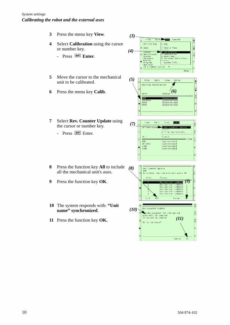
3 Press the menu key View.
4 Select Calibration using the cursor or number key.- Press Enter.
5 Move the cursor to the mechanical unit to be calibrated.
6 Press the menu key Calib.
7 Select Rev. Counter Update using the cursor or number key. - Press Enter.
8 Press the function key All to include all the mechanical unit's axes.
9 Press the function key OK.
10 The system responds with: “Unit name” synchronized.
11 Press the function key OK.
(3)
(4)
(5)
(6)
(7)
(8)
(9)
(10)
(11)

System settingsCalibrating the robot and the external axes
504 874-102 11
2.3 Recalibrating the axes This measure is necessary when the external axes lack calibration values or you wish to recalibrate the axes. NOTE! This procedure should not be used if calibration values already exist for the axis in question. You should be aware that the programmed positions can change depending on whether the new calibrated position differs from the previous position.The chapter describes the procedure for the positioner, not for the robot. (Specialist know-how, which is not described here, and equipment are required to calibrate the robot's axes.) Calibration of the external axes is performed in different ways depending on the type of positioner in question.
2.3.1 Positioners of the types A and L
1 Move the positioner's axes (axis) to respective zero positions (synchronization marking). - Be precise when adjusting the position of the axis so that it lies in the
centre of marking. The marking is made up of a machined groove or a machined notch on the gearbox respective faceplates.
2 Press Misc
3 Move the cursor to Service - Press Enter.
4 Press the menu key View.
5 Select Calibration using the cursor or number key- Press Enter.
(2)
(3)
(4)
(5)
System settingsCalibrating the robot and the external axes
12 504 874-102
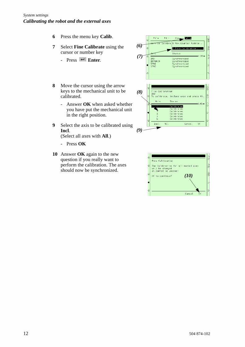
6 Press the menu key Calib.
7 Select Fine Calibrate using the cursor or number key - Press Enter.
8 Move the cursor using the arrow keys to the mechanical unit to be calibrated.- Answer OK when asked whether
you have put the mechanical unit in the right position.
9 Select the axis to be calibrated using Incl. (Select all axes with All.)- Press OK
10 Answer OK again to the new question if you really want to perform the calibration. The axes should now be synchronized.
(7)
(6)
(9)
(8)
(10)

System settingsCalibrating the robot and the external axes
504 874-102 13
2.3.2 Positioners with two position units of the types B, C, D, K or R
1 Move the positioner's axes (axis) to their respective zero positions (synchronization marking).- Be precise when adjusting the position of the axis so that it lies in the
centre of marking. The marking is made up of a machined groove or a machined notch on the gearbox respective faceplate.
2 Press Misc
3 Move the cursor to Service - Press Enter.
4 Press the menu key View.
5 Select Calibration using the cursor or number key- Press Enter.
6 Press the menu key Calib.
7 Select Fine Calibrate using the cursor or number key - Press Enter.
(2)
(3)
(4)
(5)
(6)
(7)

System settingsCalibrating the robot and the external axes
14 504 874-102
8 Move the cursor using the arrow keys to the mechanical unit to be calibrated.- Answer OK when asked whether
you have put the mechanical unit in the right position.
9 Select the axis to be calibrated using Incl. (Select all axes with All.)- Press OK
10 Answer OK again to the new question if you really want to perform the calibration. The axes should now be synchronized.
11 A program must now be run in order to accurately set the position of the table switching axis. IRBP Calibration, see IRBP Driver Documentation - Run the program to set the calibration position. - The synchronizing positions of the remaining axes are not affected by
this program.
(8)
(9)
(10)

System settingsCalibrating the robot and the external axes
504 874-102 15
2.3.3 Positioners of the types C Index
1 Move the positioner's axes (axis) to their respective zero positions (synchronization marking).- Be precise when adjusting the position of the axis so that it lies in the
centre of marking. The marking is made up of a machined groove or a machined notch on the gearbox respective faceplate.
2 Press Misc
3 Move the cursor to Service - Press Enter.
4 Press the menu key View.
5 Select Calibration using the cursor or number key- Press Enter.
6 Press the menu key Calib.
7 Select Fine Calibrate using the cursor or number key - Press Enter.
(2)
(3)
(4)
(5)
(6)
(7)

System settingsCalibrating the robot and the external axes
16 504 874-102
8 Move the cursor using the arrow keys to the mechanical unit to be calibrated.- Answer OK when asked whether
you have put the mechanical unit in the right position.
9 Select the axis to be calibrated using Incl. (Select all axes with All.)- Press OK
10 Answer OK again to the new question if you really want to perform the calibration. The axes should now be synchronized.
11 A program must now be run in order to accurately set the position of the table switching axis. - Run the program to set the limit switches.
(8)
(9)
(10)

System settingsDefinition of the tool data (tload)
504 874-102 17
3 Definition of the tool data (tload)These are the movement related data that should be defined first. All movement is dependent on this definition.When using the Collision Detection functionality it is most important to have the right tool load in your tool data.Recommended data components for the tool:robhold: truetframe: 5-point TCP&Z is normally used with weaving during
MIG/MAG welding.Without weaving 4-point TCP is sufficient.TCP is defined according to the description in section 4, S4C User's Guide, Calibration, Defining tools.
tload: Values for the supplied standard welding guns and guns with a swan neck:
The five standard welding gun types above are predefined with the right tload in the module Tooldata.sys.
- Always use one of these tools when you are using a standard welding gun.
- Duplicate and change the name of the tool data if you want to make your own tool.
- If you use a non-standard welding gun it is necessary to run the load_identify service routine.
3.1 Setup welding gun whithout BullsEye®IIThe position of the robot and its movements are always related to its tool coordinate system, i.e. the TCP and tool orientation. To get the best performance,it is important to define the tool coordinate system as correctly as possible. For more information, see the User’s guide, Chapter "7 Defining Tools"
Welding gun type Swan neck Weightkg
X mm
Y mm
Z mm
ESAB PSF 315R 22 degrees 3.3 -60 0 57
ESAB PSF 500R 22 degrees 3,3 -60 0 57
Dinse PKI 500 22 degrees 3,3 -35 0 90
Binzel WH 455 22 degrees 3,3 -35 0 55
Dinse PP ALU 22 degrees 4,4 -20 0 120

System settingsDefinition of the tool data (tload)
18 504 874-102
3.2 Setup welding gun when using BullsEye®II (option)BullsEye® II provides completely automated Tool Center Point (TCP) definition.Choose the right tool before starting the SetupBullseye routine.
1 Select (Program)
2 Select View
3 Select 6 (Modules)- Press Enter.
4 Select Tcpdata- Press Enter.
5 Select SetupBullsEye- Press Enter.
(1)
(2)(3)
(4)
(5)

System settingsDefinition of the tool data (tload)
504 874-102 19
6 To change tool (welding gun):- Move cursor to selected tool
(welding gun).- Press Enter.
7 Select tool (welding gun) from list.- Press OK.
8 Right type of welding gun is selected.
(6)
(7)
(8)

System settingsDefinition of the tool data (tload)
20 504 874-102

System settingsDefinition of the user co-ordinate system & work object
504 874-102 21
4 Definition of the user co-ordinate system & work objectSome measures must be taken before the definition.
• The tool data for the particular welding gun must be defined, See "Definition of the tool data (tload)" on page 17.
• The right tool with the correct TCP must be activated in the jogging menu.• The mechanical unit for which the user co-ordinate system and work object
are to be defined must be activated.• The mechanical unit's axis (axes) should be set to zero degrees (zero
position).
System settingsDefinition of the user co-ordinate system & work object
22 504 874-102
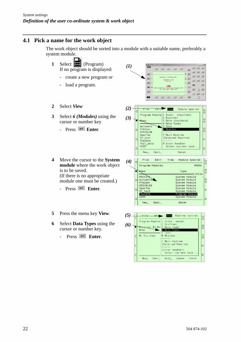
4.1 Pick a name for the work objectThe work object should be sorted into a module with a suitable name, preferably a system module.
1 Select (Program)If no program is displayed:- create a new program or - load a program.
2 Select View
3 Select 6 (Modules) using the cursor or number key - Press Enter.
4 Move the cursor to the System module where the work object is to be saved. (If there is no appropriate module one must be created.)- Press Enter.
5 Press the menu key View.
6 Select Data Types using the cursor or number key.- Press Enter.
(1)
(2)
(3)
(4)
(5)
(6)
System settingsDefinition of the user co-ordinate system & work object
504 874-102 23
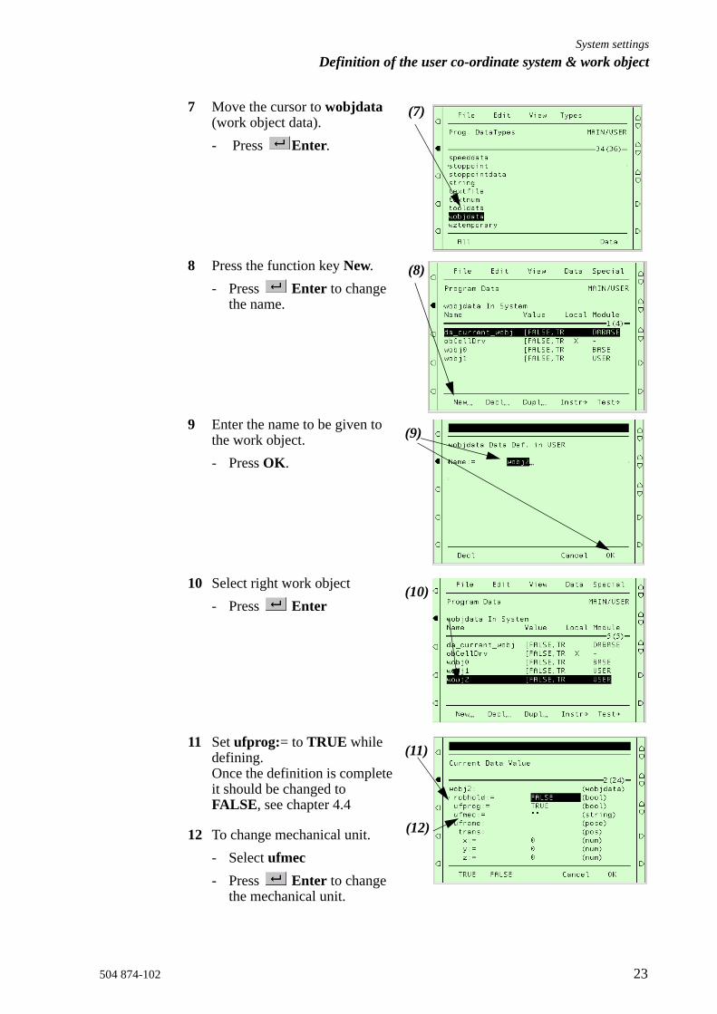
7 Move the cursor to wobjdata (work object data).- Press Enter.
8 Press the function key New.- Press Enter to change
the name.
9 Enter the name to be given to the work object.- Press OK.
10 Select right work object- Press Enter
11 Set ufprog:= to TRUE while defining. Once the definition is complete it should be changed to FALSE, see chapter 4.4
12 To change mechanical unit.- Select ufmec- Press Enter to change
the mechanical unit.
(7)
(8)
(9)
(10)
(11)
(12)
System settingsDefinition of the user co-ordinate system & work object
24 504 874-102
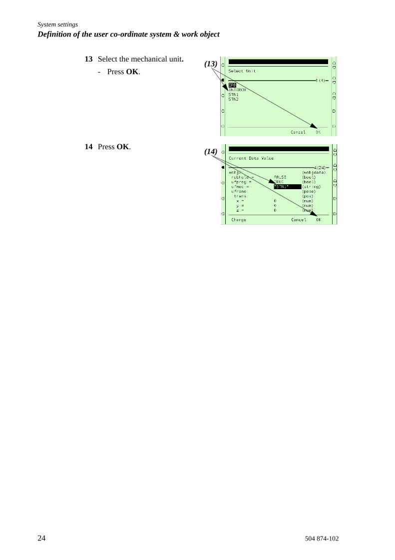
13 Select the mechanical unit.- Press OK.
14 Press OK.
(13)
(14)

System settingsDefinition of the user co-ordinate system & work object
504 874-102 25
4.2 Definition of the user co-ordinate system• The definition should be performed using a 4-point method. • Make sure that the positioner's axes are synchronized and set at 0 degrees.• Select a point on the mechanical unit's faceplate by the plate's
synchronization mark. You will always get a more accurate measurement if you measure as far out on the plate as possible, alternatively extend the plate's radius so that you can measure at a point on the outer edge of the area of movement. (You can easily make a bar that is bolted to the faceplate.)
4.2.1 Positioner IRBP types L / K / RUses a single axis user co-ordinate definition, see the robot's User's Manual chap. 10.6.2
4.2.2 Positioner IRBP types A / B / DUse double axes user co-ordination definition Method 2, see the robot's User's Manual chap 10.6.4
4.2.3 Positioner IRBP types C / C Index as well as fixed table, S (Stationary).No rotating user co-ordinate system is used here. Measure the object according to the methods for Work object, see the robot's User's Manual chap. 10.8

System settingsDefinition of the user co-ordinate system & work object
26 504 874-102
4.3 Changing the work object to a moving work object
1 Select (Program)
2 Select View
3 Select 6 (Modules) using the cursor or number key - Press Enter.
4 Move the cursor to the System module that contains Work Object.- Press Enter.
5 Press the menu key View.
6 Select Data Types using the cursor or number key- Press Enter.
7 Move the cursor to wobjdata (work object data)- Press Enter.
(1)
(2)
(3)
(4)
(5)
(6)
(7)

System settingsDefinition of the user co-ordinate system & work object
504 874-102 27
8 Move the cursor to data to be edited. - Press Enter.
9 Move the cursor to ufprog:=- Select state FALSE- Press the function key OK.
(8)
(9)
System settingsDefinition of the user co-ordinate system & work object
28 504 874-102
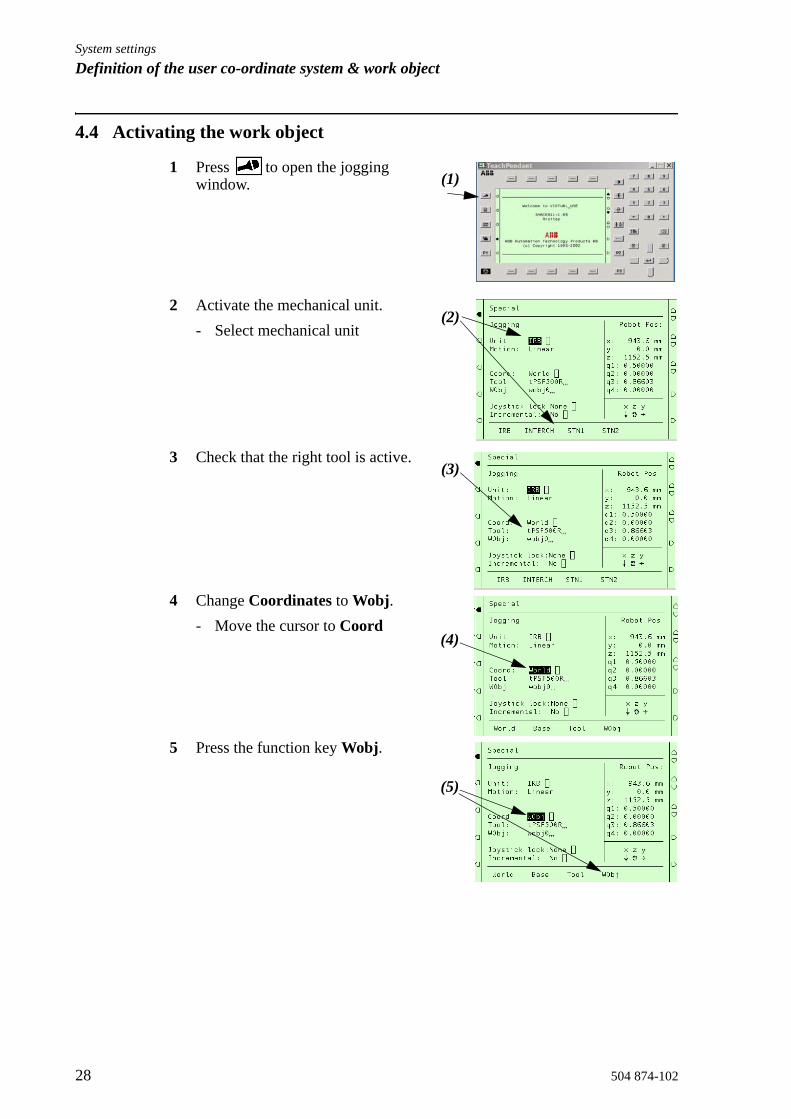
4.4 Activating the work object
1 Press to open the jogging window.
2 Activate the mechanical unit.- Select mechanical unit
3 Check that the right tool is active.
4 Change Coordinates to Wobj.- Move the cursor to Coord
5 Press the function key Wobj.
(1)
(2)
(3)
(4)
(5)

System settingsDefinition of the user co-ordinate system & work object
504 874-102 29
6 Change Work Object to the WorkObject that is to be defined for the mechanical unit in question.- Move the cursor to Wobj - Press Enter.
7 Select the right WorkObject and - Press Enter.
(6)
(7)

System settingsDefinition of the user co-ordinate system & work object
30 504 874-102
4.5 Deactivate Work object
1 Press to open the jogging window.
2 Move the cursor to Wobj and - Press Enter.
3 Select wobj0 and - Press Enter.
(1)
(2)
(3)
System settingsRestart
504 874-102 31
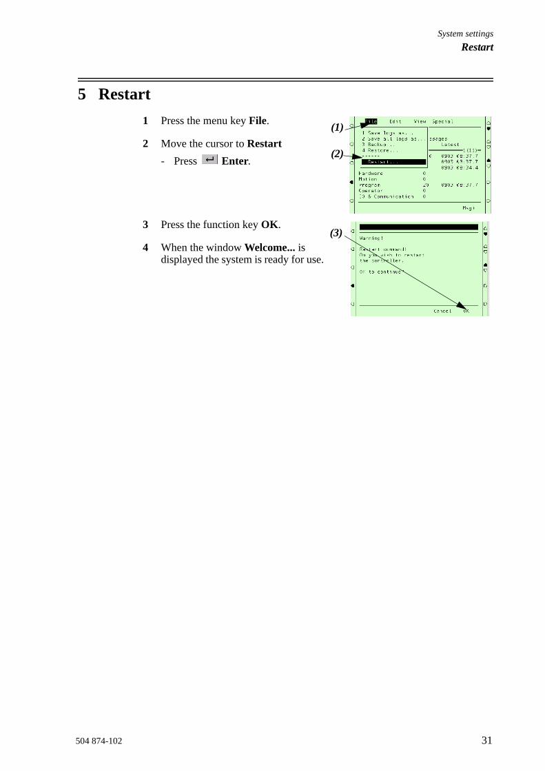
5 Restart1 Press the menu key File.
2 Move the cursor to Restart - Press Enter.
3 Press the function key OK.
4 When the window Welcome... is displayed the system is ready for use.
(1)
(2)
(3)

System settingsRestart
32 504 874-102

System settingsBacking up the system
504 874-102 33
6 Backing up the systemThe backup function saves all system parameters, system modules and program modules in a context. If desired, all logs are also saved. The data will be saved in a directory specified by the user.Note Backup can not be performed during execution of the main task or if there are a lot of background tasks currently in action.
6.1 To preform a Backup
1 Press Misc
2 Move the cursor to Service - Press Enter.
3 Press the menu key File.
4 Select Backup using the cursor or number key.- Press Enter.
5 Choose whether or not all logs are to be saved by selecting the Include logs field.
6 Check that the right destination directory is selected- Press Enter to select
destination.If a cold start is perfomed, the backup need to be saved in a separate directory on the robot unit:hd0a:\backup\bakmmdd (mmdd=month day)Otherwise the folder will be erased.
(1)
(2)
(3)(4)
(5)
(6)

System settingsBacking up the system
34 504 874-102
7 Select a backup directory. A default directory is suggested, consisting of a prefix and current date, BAKmmdd.If you want to change directory:- Press Enter- Select, or create a new, directory.- Press Unit to change massmemory unit.- Press OK to start the backup.
8 Press the function key OK.
9 Move the cursor to the directory the system parameters are to be saved in.
10 Press the function key OK to save all parameters in the selected directory.
11 When the system parameters have been saved.- Press Enter.

System settingsSpeed data for external axes
504 874-102 35
7 Speed data for external axesUse the following max. speed data for IRBP-axis:
IRBP-positioner
MTC250 180 degrees/s
MTC750 150 degrees/s
MTC2000 90 degrees/s
MTC5000 39 degrees/s
MIC1.1 90 degrees/s
MIC1.2 90 degrees/s
MIC2.1 90 degrees/s
MIC2.2 90 degrees/s

System settingsSpeed data for external axes
36 504 874-102

System settingsDrivers
504 874-102 37
8 DriversIn order to ensure the function of the IRBP positioner while operating a number of drivers are supplied. The main program is the easiest and fastest way to get started. It includes routines were you can put programs for each mechanical unit. The IrbpMoveToStn driver is used to give, on IRBP positioner of the types B, C, D, K and R, unit rotation and shift the mechanical units towards the robot side/operator side. Use of this driver ensures that the right load and interchange position is used.
• For more information, see IRBP Driver Documentation
8.1 Driver set-upWhen you start the main program for the first time you will be guided through a setup. If you have an IRBP positioner of type B, C, D, K or R it is important that STN1 is synchronized against the robot near the mechanical stop. Otherwise the setup will not work accurately.

System settingsDrivers
38 504 874-102
8.1.1 Run IRBP Service routine The IRBP_Service Routine is used to set up the drivers and to perform manual operations. It is also an example of how you can use the IRBP drivers in your own program.For a complete documentation of the IRBP driver functionality, please refer to the IRBP Driver Reference Manual.
1 Select (Program)
2 Select Special
3 Select 6 (Call Service Routine)- Press Enter.
4 Select IRBP Service- Press OK to continue
5 Start program (Run Service)- Press Start to continue
(1)
(2)(3)
(4)
(4)
(5)
System settingsDrivers
504 874-102 39
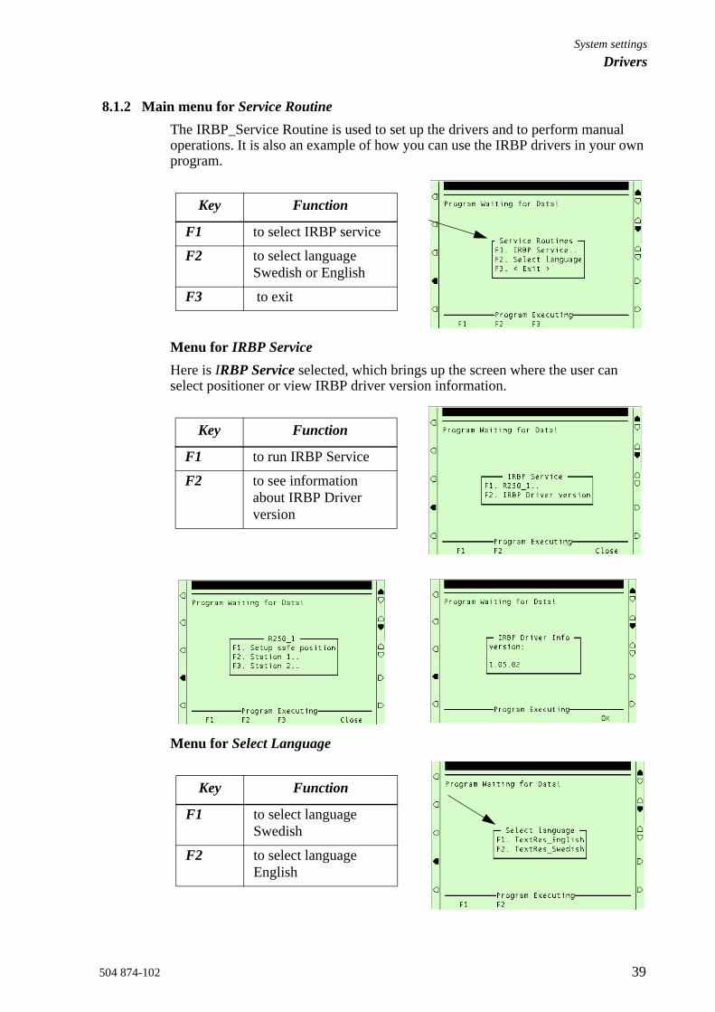
8.1.2 Main menu for Service RoutineThe IRBP_Service Routine is used to set up the drivers and to perform manual operations. It is also an example of how you can use the IRBP drivers in your own program.
Menu for IRBP ServiceHere is IRBP Service selected, which brings up the screen where the user can select positioner or view IRBP driver version information.
Menu for Select Language
Key Function
F1 to select IRBP service
F2 to select language Swedish or English
F3 to exit
Key Function
F1 to run IRBP Service
F2 to see information about IRBP Driver version
Key Function
F1 to select language Swedish
F2 to select language English

System settingsDrivers
40 504 874-102
Positioner menu
On the positioner screen you can select which station you want to work with or you can setup the Safe Position for this positioner.
1 Select F1 on IRBP Service menu.
Positioner screen
Station menu
On the station menu you will find:- The load identification procedure, see Load identification procedure on
page 62.- Setup of working positions for each one of your mechanical units, see
Working positions on page 49.Station menu
Key Function
F1 Setup safe position
F2 Station 1
F3 Station 2
Key Function
F1 Load identify
F2 Process position
F3 Load position
F3 Service position
(1)

System settingsDrivers
504 874-102 41
8.2 Safe positionThis should be a position where the robot is free from the IRBP positioner working area.
1 Select F1 on Positioner Screen to setup the Safe Position for this positioner.
2 Press OK
First, the Robot Safe Position is teached. The driver requires this position to safely perform a station interchange.
3 Move the robot to a safe position for positioners work area.- Press Start
(1)
(2)
(3)

System settingsDrivers
42 504 874-102

System settingsDrivers
504 874-102 43
8.3 IRBP positioner Interchange calibration
8.3.1 IRBP positioner with mechanical stops If your IRBP positioner is of type B, C, D, K or R and has mechanical stops. In order to get the right torque against the stop you must calibrate the positions for side 1 and side 2. The driver setup will guide you through this calibration.
1 Select (Program)
2 Select Special
3 Select 6 (Call Service Routine)- Press Enter.
4 Select IRBP Calib- Press OK to continue
5 Select F1- IRBP Calibration
(1)
(2)
(3)
(4)
(5)

System settingsDrivers
44 504 874-102
6 Select F1- IRBP positioner
7 Start of interchange calibration- Press OK to continue
8 Change operating mode to manual- Press OK to continue- Change to MANUAL MODE- Restart
9 Move robot to a safe position outside positioners working area- Press OK to continue
10 Warn user before indexing positioner. The station interchange might now move. Make sure that you keep your safety distance.- Press OK to continue
(6)
(7)
(8)
(9)
(10)

System settingsDrivers
504 874-102 45
11 Searching for interchange positionFor positioners with mechanical stop, the interchange positions are found by measuring the torque against the stop.
12 Calibration finished- When the calibration is
finished, the screen indicated that the positioner passed the calibration.
- Press OK to continue.
13 After the calibration, it is time to program the Process positions, see Process position on page 49. A process position is the position the side towards the robot will be in after the interchange. Program it to be in a good starting position for the first weld to reduce cycle time.
(11)
(12)

System settingsDrivers
46 504 874-102
8.3.2 IRBP positioner without mechanical stops IRBP positioner of type B, C, D, K or R. In order to get the right position you must calibrate the positions for side 1 and side 2. The driver setup will guide you through this calibration.
1 Select (Program)
2 Select Special
3 Select 6 (Call Service Routine)- Press Enter.
4 Select IRBP Calib- Press OK to continue
5 Select F1- IRBP Calibration
6 Select F1- IRBP positioner
(1)
(2)
(3)
(4)
(5)
(6)

System settingsDrivers
504 874-102 47
7 Start of interchange calibration- Press OK to continue
8 Change operating mode to manual- Press OK to continue- Change to MANUAL MODE- Restart
9 Move robot to a safe position outside positioners working area- Press OK to continue
10 Warn user before indexing positioner. The station interchange might now move. Make sure that you keep your safety distance.- Press OK to continue.
11 After interchange and no limit switch signal is high, the user is prompted to jog in position.- Press OK to continue.- Jog interchange axis in
position
(7)
(8)
(9)
(10)
(11)
System settingsDrivers
48 504 874-102
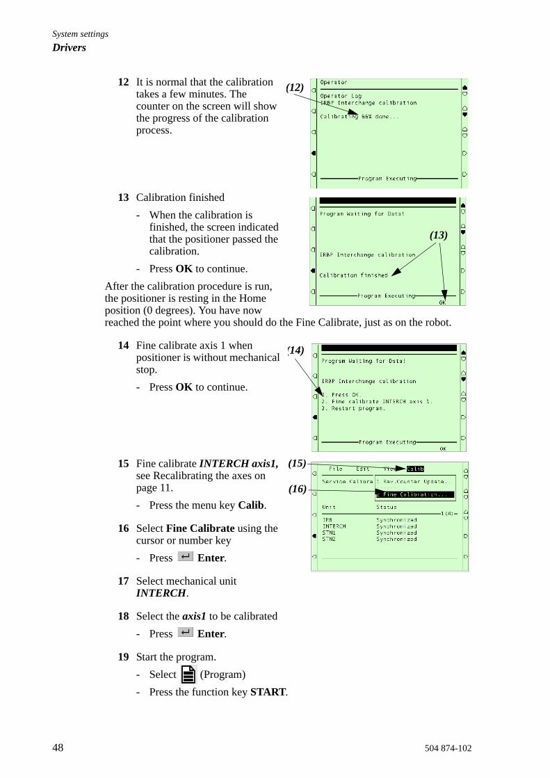
12 It is normal that the calibration takes a few minutes. The counter on the screen will show the progress of the calibration process.
13 Calibration finished- When the calibration is
finished, the screen indicated that the positioner passed the calibration.
- Press OK to continue.After the calibration procedure is run, the positioner is resting in the Home position (0 degrees). You have now reached the point where you should do the Fine Calibrate, just as on the robot.
14 Fine calibrate axis 1 when positioner is without mechanical stop.- Press OK to continue.
15 Fine calibrate INTERCH axis1, see Recalibrating the axes on page 11.- Press the menu key Calib.
16 Select Fine Calibrate using the cursor or number key - Press Enter.
17 Select mechanical unit INTERCH.
18 Select the axis1 to be calibrated - Press Enter.
19 Start the program.- Select (Program)- Press the function key START.
(12)
(13)
(14)
(15)
(16)

System settingsDrivers
504 874-102 49
8.4 Working positionsThese positions will speed up and simplify your process. You will be guided through a setup of load position, process position and service position for each one of your mechanical units.Station menu
If you would like to change these values just run the IRBP Service routine. See “Run IRBP Service routine” on page 38.
8.4.1 Process positionA process position is the position the side towards the robot will be in after the interchange. Program it to be in a good starting position for the first weld to reduce cycle time.
1 Positioner screenSelect which station you want to work with.
2 Station menu Press F2 for setup of Process position
Key Function
F1 Load identify
F2 Process position
F3 Load position
F3 Service position
(1)
(2)

System settingsDrivers
50 504 874-102
3 IRBP Process position- Press JOG to jog to position- Press VALUE to manually
entering each axis value
4 Jog to process position- Press Start
5 Showing the current value for process position.- Enter new value- Press OK
Now the positioner moves to its new process position.
6 Use this process position?- Press “Yes” to use this
position.- Press “No” to redo
(3)
(4)
(5)
(6)

System settingsDrivers
504 874-102 51
8.4.2 Load positionA load position is the position the side towards the operator will be in after the interchange. Program it in a good position for the operator to load/unload parts.
1 Positioner screenSelect which station you want to work with.
2 Station menu Press F3 for setup of Load position
3 IRBP Load positionYou can set up the Load position either by choosing a value or by jogging the station to the right position.- Press JOG to jog to position- Press VALUE to manually
entering each axis value
4 Jog to load position- Press Start
(1)
(2)
(3)
(4)

System settingsDrivers
52 504 874-102
5 Showing the current value for load position.- Enter new value- Press OK.
Now the positioner moves to its new load position.
6 Use this load position?- Press “Yes” to use this
position.- Press “No” to redo
(5)
(6)

System settingsDrivers
504 874-102 53
8.4.3 Service positionA service position is a position where the operator can inspect or do service on the work piece or fixture.
1 Positioner screenSelect which station you want to work with.
2 Station menu Press F4 for setup of Service positions
3 IRBP Service positionsYou can set up the Service position either by choosing a value or by jogging the station to the right position. - Press JOG to jog to service
position- Press VALUE to manually
entering each axis value
4 Jog to service position- Press Start
(1)
(2)
(3)
(4)
System settingsDrivers
54 504 874-102
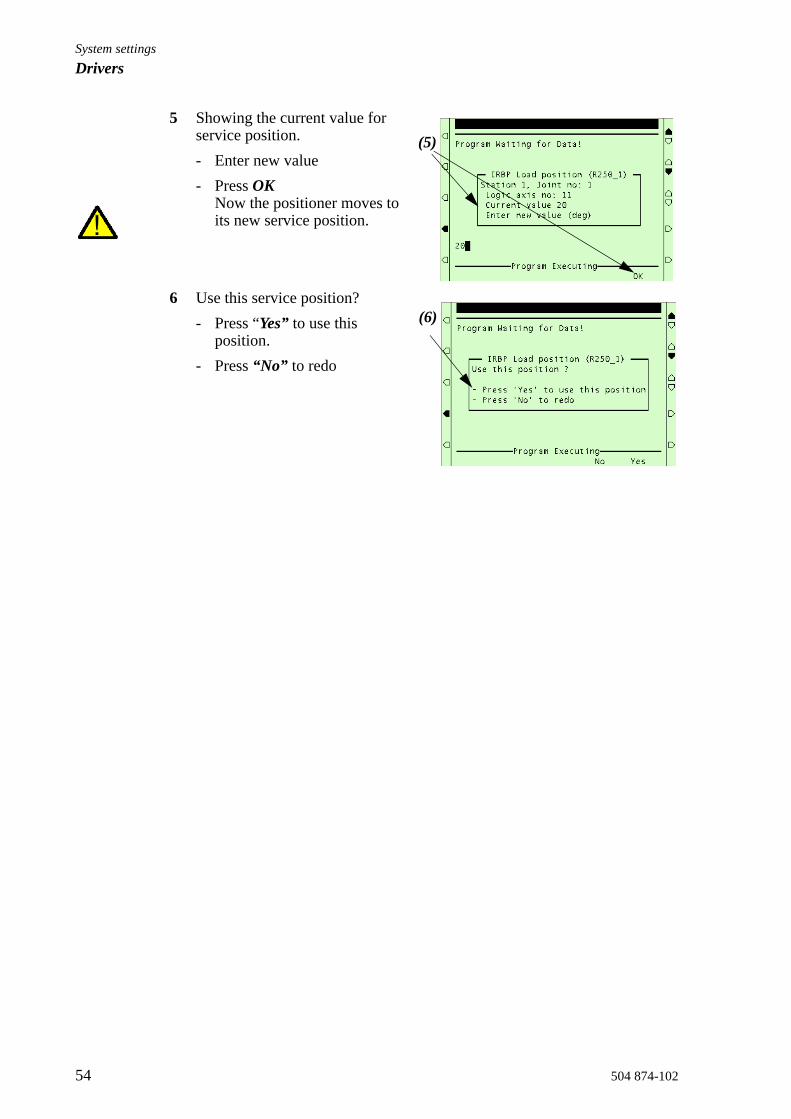
5 Showing the current value for service position.- Enter new value- Press OK
Now the positioner moves to its new service position.
6 Use this service position?- Press “Yes” to use this
position.- Press “No” to redo
(5)
(6)

System settingsDrivers
504 874-102 55
8.5 ActivationThe driver IrbpActMechUnit is used to activate (switch on) a mechanical unit. For example STN1. This driver performs no movement.
• See IRBP Driver Documentation
8.6 DeactivationThe driver IrbpDeactMechUnit is used to deactivate (switch off) a mechanical unit. For example STN1. This driver performs no movement.
• See IRBP Driver Documentation
8.7 Operator's panelDriver to handle the operator's panel and the associated functions. Among others, resetting of safety, any options such as roller doors, etc.
- Program start- Program stop- Start of process (Resetting of safety, Operator ready, Cancel operator
ready)• See OP Driver Documentation

System settingsDrivers
56 504 874-102

System settingsIdentification of load data for positioners IRBP
504 874-102 57
9 Identification of load data for positioners IRBP Since the data of the different loads that can be mounted on the external positioner can be quite difficult to compute, there is a load identification procedure which computes the necessary load data by moving the positioner. Here we will describe which parameters are identified with the load identification and then briefly describe the load identification movements. If you run the load identification for the first time on a specific type of positioner, it is recommended that you first run the procedure in slow test mode to prevent any collisions. See “Load identification procedure” on page 62.
9.1 Load Identification for IRBP L /CA simplified view of positioner IRBP L is shown in Figure 1. Load identification can be performed in any position for this positioner.
Figure 1 Simplified view of positioner IRBP_L.
Figure 2 Simplified view of positioner IRBP_C.
The parameters that are identified are: centre of gravity in a plane perpendicular to the axis, and moments of inertia around the axis, see Figure 3. Note that the mass of the load must be known in advance. The mass data is entered when performing the load identification. See “Load identification procedure” on page 62. Together with the identified parameters, a measurement accuracy is also given, indicating how successful the identification was.
axis 1
axis 1
System settingsIdentification of load data for positioners IRBP
58 504 874-102
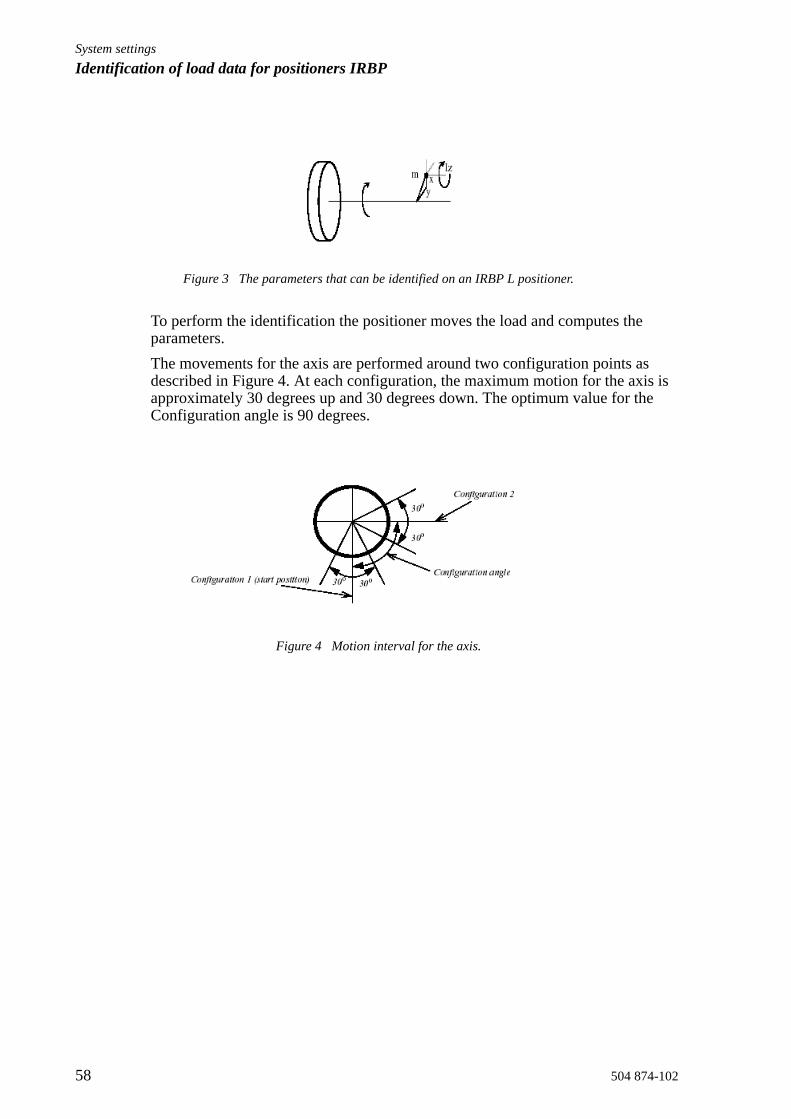
Figure 3 The parameters that can be identified on an IRBP L positioner.
To perform the identification the positioner moves the load and computes the parameters.The movements for the axis are performed around two configuration points as described in Figure 4. At each configuration, the maximum motion for the axis is approximately 30 degrees up and 30 degrees down. The optimum value for the Configuration angle is 90 degrees.
Figure 4 Motion interval for the axis.

System settingsIdentification of load data for positioners IRBP
504 874-102 59
9.2 Load Identification for IRBP KA simplified view of positioner IRBP K is shown in Figure 5. Load identification is allowed on axes 2 and 3 for this positioner. Load identification can only be performed when axis 1 is in one of its end positions. This is checked by the load identification procedure.
Figure 5 Simplified view of positioner IRBP K.
The identification movements for each axis are the same as for the IRBP L positioner.The identified parameters are also the same.

System settingsIdentification of load data for positioners IRBP
60 504 874-102
9.3 Load Identification for IRBP RA simplified view of the IRBP R positioner is shown in Figure 6. The parameters that are identified are: centre of gravity in a plane perpendicular to the axis, and three moments of inertia at the centre of gravity. Note that both the mass of the load and the distance z to the centre of gravity must be known in advance. These data are entered when performing the load identification. See “Load identification procedure” on page 62.
Figure 6 Simplified view of positioner IRBP R.
One part of the identification movements for one axis are the same as for the IRBP L positioner. To find the extra moments of inertia we also move the interchange axis with the load to two different positions. The movements for the interchange axis are the movements described in Figure 6 but only at one configuration point. It is important to remember that the identification on one axis will be correct only if there is no load mounted on the other axis.

System settingsIdentification of load data for positioners IRBP
504 874-102 61
9.4 Load Identification for IRBP A, B and DA simplified view of positioner IRBP A/ B/ D is shown in Figure 7. When the identification is performed, the positioner must be positioned so that the z-axis is horizontal.This is checked by the load identification procedure. If axis 1 is too far from this position the load identification procedure will suggest which angle it should be moved to.
Figure 7 Simplified view of positioner IRBP A.
The parameters that are identified are: centre of gravity and three moments of inertia at the centre of gravity, see Figure 7. The mass of the load must be known in advance and it is entered when performing the load identification. See “Load identification procedure” on page 62.The motion for each axis is, in principal, the same as for the IRBP L positioner, see Figure 4. However, axis 1 only performs its movements around one configuration point.It should be noted in the case of this positioner that some of the load calculations are quite complicated, especially for the moments of inertia. Therefore, the level of the load identification accuracy may be lower than for the other positioners. This is generally not a problem since possible errors in the load data are normally very small compared to the combined effect of load and positioner together.

System settingsIdentification of load data for positioners IRBP
62 504 874-102
9.5 Load identification procedure• Make sure that the payload is mounted on the IRBP positioner’s
end effectors (turntable)• Make sure that the positioner axes, which will move during the
identification, aren’t close to their corresponding working range limits.• Make sure that the mechanical unit is activated.• Make sure that the speed override is set to 100%.• The Payload to identify must be defined as a PERS variable (with default
data). It is recommended to define the payload in the system module USER.SYS because then the payload is always available in the system.
1 Select (Program)
2 Select Special
3 Select 6 (Call Service Routine)- Press Enter.
4 Select IRBP Service- Press OK
5 Start program RunService- Press Start
(1)
(2)
(3)
(4)
(4)
(5)

System settingsIdentification of load data for positioners IRBP
504 874-102 63
6 Main menu for Service Routine- Select F1 - IRBP Service
7 Here is IRBP Service selected, which brings up the screen where the user can select positioner or view IRBP driver version information.- Select F1 - positioner
Positioner screen
8 On the positioner screen you can select which station you want to work with or you can setup the Safe Position for this positioner.- Select which station you want
to work with.- You will now be guided
through the load identification procedure
Station menu Load Identification
9 Press F1 for load identification
10 Enter the total weight in kg of the fixture and work piece together.- Press OK to continue.
(6)
(7)
(8)
(9)
(10)
System settingsIdentification of load data for positioners IRBP
64 504 874-102
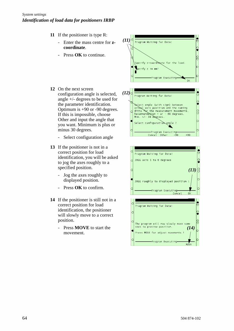
11 If the positioner is type R:- Enter the mass centre for z-
coordinate.- Press OK to continue.
12 On the next screen configuration angle is selected, angle +/- degrees to be used for the parameter identification. Optimum is +90 or -90 degrees. If this is impossible, choose Other and input the angle that you want. Minimum is plus or minus 30 degrees.- Select configuration angle
13 If the positioner is not in a correct position for load identification, you will be asked to jog the axes roughly to a specified position.- Jog the axes roughly to
displayed position.- Press OK to confirm.
14 If the positioner is still not in a correct position for load identification, the positioner will slowly move to a correct position.- Press MOVE to start the
movement.
(11)
(12)
(13)
(14)
System settingsIdentification of load data for positioners IRBP
504 874-102 65
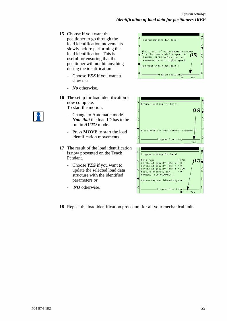
15 Choose if you want the positioner to go through the load identification movements slowly before performing the load identification. This is useful for ensuring that the positioner will not hit anything during the identification. - Choose YES if you want a
slow test.- No otherwise.
16 The setup for load identification is now complete. To start the motion:- Change to Automatic mode.
Note that the load ID has to be run in AUTO mode.
- Press MOVE to start the load identification movements.
17 The result of the load identification is now presented on the Teach Pendant. - Choose YES if you want to
update the selected load data structure with the identified parameters or
- NO otherwise.
18 Repeat the load identification procedure for all your mechanical units.
(15)
(16)
(17)

System settingsIdentification of load data for positioners IRBP
66 504 874-102
9.5.1 Error handlingIf an error should occur during the load identification movements, the procedure must be restarted from the beginning.
1 Confirm the error.
2 Press Start
To interrupt and leave the load identification procedure:
1 Stop the program.
2 Close the program.
9.5.2 LimitationsIf the measurement accuracy is low, i.e. lower than 80%, a significant error may be present in the result of the load identification. If this is the case, a higher accuracy may be achieved by just repeating the load identification once again. If this does not work, the torques measured in the identification are probably too small and the tool and/or payload data must be set manually. This is typically the case when the mass of the load is small (10% or less of the maximum load). It can also occur when the load has a particular symmetry property, for example, if the load is symmetrical around the rotating axis. Note, however, that even if the measurement accuracy is low, some of the identified parameters may still be useful.If the load identification movements are interrupted by some kind of stop (Program Stop, Emergency Stop, etc.), the load identification must be restarted from the beginning. This is done automatically if you:
1 Confirm the error.
2 Press Start
System settingsMechUnitLoad Defines a payload for a mechanical unit
504 874-102 67
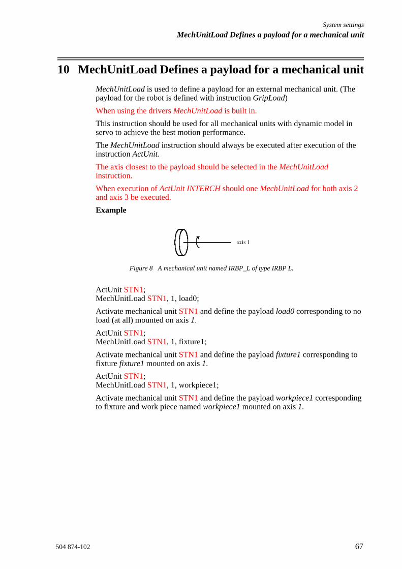
10 MechUnitLoad Defines a payload for a mechanical unitMechUnitLoad is used to define a payload for an external mechanical unit. (The payload for the robot is defined with instruction GripLoad)When using the drivers MechUnitLoad is built in.This instruction should be used for all mechanical units with dynamic model in servo to achieve the best motion performance.The MechUnitLoad instruction should always be executed after execution of the instruction ActUnit.The axis closest to the payload should be selected in the MechUnitLoad instruction.When execution of ActUnit INTERCH should one MechUnitLoad for both axis 2 and axis 3 be executed. Example
Figure 8 A mechanical unit named IRBP_L of type IRBP L.
ActUnit STN1;MechUnitLoad STN1, 1, load0;Activate mechanical unit STN1 and define the payload load0 corresponding to no load (at all) mounted on axis 1.ActUnit STN1;MechUnitLoad STN1, 1, fixture1;Activate mechanical unit STN1 and define the payload fixture1 corresponding to fixture fixture1 mounted on axis 1.ActUnit STN1;MechUnitLoad STN1, 1, workpiece1;Activate mechanical unit STN1 and define the payload workpiece1 corresponding to fixture and work piece named workpiece1 mounted on axis 1.

System settingsMechUnitLoad Defines a payload for a mechanical unit
68 504 874-102
10.1 ArgumentsMechUnitLoad MechUnit AxisNo Load
MechUnit (Mechanical Unit) Data type: mecunit
The name of the mechanical unit.
AxisNo (Axis Number) Data type: num
The axis number, within the mechanical unit, that holds the load.
Load Data type: loaddata
The load data that describes the current payload to be defined.
10.2 Program executionAfter execution of MechUnitLoad, when the robot and external axes have come to a standstill, the specified load is defined for the specified mechanical unit and axis. This means that the payload is controlled and monitored by the control system.The default payload at cold start-up, for a certain mechanical unit type, is the predefined maximal payload for this mechanical unit type.When some other payload is used, the actual payload for the mechanical unit and axis should be redefined with this instruction. This should always be done after activation of the mechanical unit.
Figure 9 Payload mounted on the end-effector of a mechanical unit.

System settingsMechUnitLoad Defines a payload for a mechanical unit
504 874-102 69
Example
Figure 10 A mechanical unit named IRBP_K of type IRBP K with three axes.
MoveL homeside1, v1000, fine, gun1;
....
ActUnit INTERCH;
The whole mechanical unit INTERCH_K is activated.
MechUnitLoad INTERCH, 2, workpiece1;
Defines payload workpiece1 on the mechanical unit INTERCH axis 2.
MechUnitLoad INTERCH, 3, workpiece2;
Defines payload workpiece2 on the mechanical unit INTERCH axis 3.
MoveL homeside2, v1000, fine, gun1
The axes of the mechanical unit INTERCH move to the switch position homeside2 with mounted payload on both axes 2 and 3.
10.3 LimitationsThe movement instruction previous to this instruction should be terminated with a stop point in order to make a restart in this instruction possible following a power failure.
10.4 Syntax
MechUnitLoad
[MechUnit’:=’] < variable (VAR) of mecunit>’,’[AxisNo ‘:=’] <expression (IN) of num ‘,’[ Load’:=’] < persistent (PERS) of loaddata >’;’

System settingsMechUnitLoad Defines a payload for a mechanical unit
70 504 874-102
10.5 Related information
Described in:
Identification of payload for external mechanical units
LoadID&CollDetect• Program muloadid.prg
Mechanical units Data Types- mecunit
Definition of load data Data Types - loaddata
Definition of payload for the robot Instructions - GripLoadData Types - tooldata


504 874-102


![MC-909 q e - zZounds.comc3.zzounds.com/media/MC909_QS-f1bb572186000f8bce9fee87a3... · 1. Press [CURSOR (down)] to move the cursor to “End Point.” 2. Turn [VALUE] toward the left](https://static.fdocuments.in/doc/165x107/5fbce98a05290813cb7876e7/mc-909-q-e-1-press-cursor-down-to-move-the-cursor-to-aoeend-pointa-2.jpg)