Arc Flash Hazard and Electrical Safety · IEEE 1584-2002 6 . Important Factors to be Considered •...
21
Arc Flash Hazard and Electrical Safety Wei-Jen Lee, PhD, PE Director and Professor Energy Systems Research Center The University of Texas at Arlington September 28, 2016
Transcript of Arc Flash Hazard and Electrical Safety · IEEE 1584-2002 6 . Important Factors to be Considered •...
Arc Flash Hazard and Electrical Safety
Wei-Jen Lee, PhD, PE
Director and Professor Energy Systems Research Center
The University of Texas at Arlington
September 28, 2016
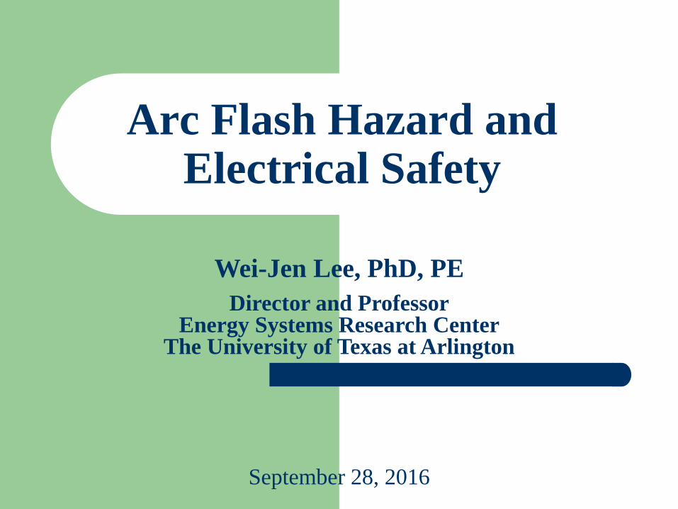
Introduction
• Arc Flash
– Arc flash is a sudden
release of heat and energy
caused by an electric arc.
– The result of the violent
event can cause destruction
of equipment, fire, and
injury not only to the
worker but also to nearby
people.
2
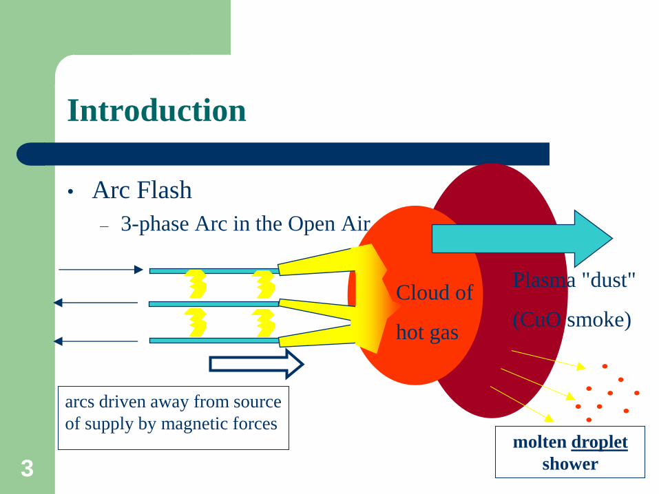
Introduction
• Arc Flash
– 3-phase Arc in the Open Air
Plasma "dust"
(CuO smoke)
arcs driven away from source
of supply by magnetic forces
Cloud of
hot gas
molten droplet
shower 3
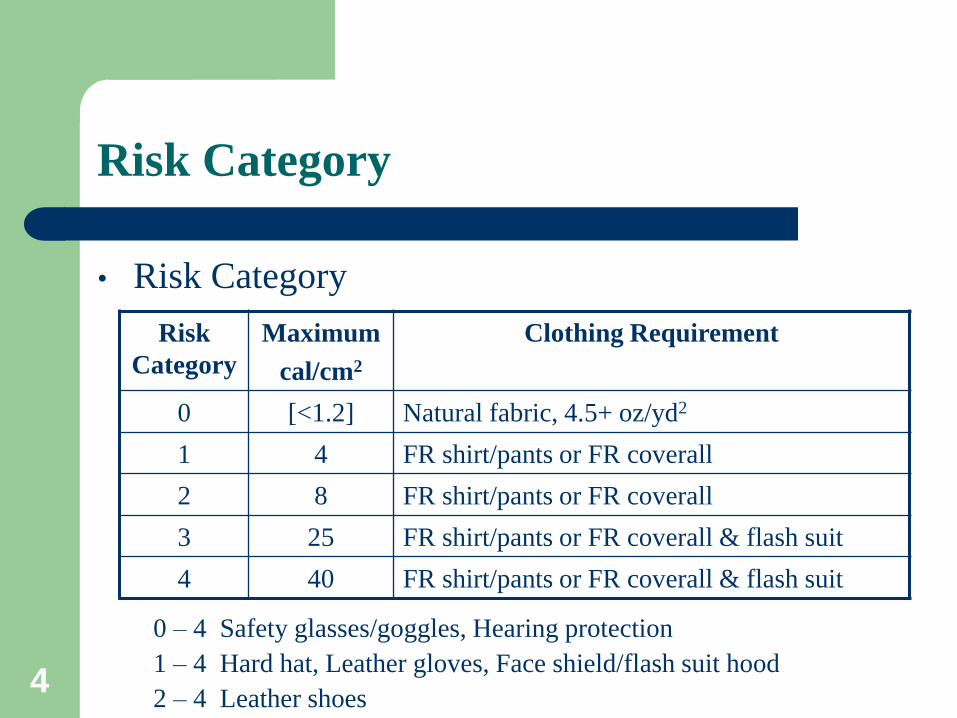
• Risk Category
Risk Category
Risk
Category
Maximum
cal/cm2
Clothing Requirement
0 [<1.2] Natural fabric, 4.5+ oz/yd2
1 4 FR shirt/pants or FR coverall
2 8 FR shirt/pants or FR coverall
3 25 FR shirt/pants or FR coverall & flash suit
4 40 FR shirt/pants or FR coverall & flash suit
0 – 4 Safety glasses/goggles, Hearing protection
1 – 4 Hard hat, Leather gloves, Face shield/flash suit hood
2 – 4 Leather shoes 4
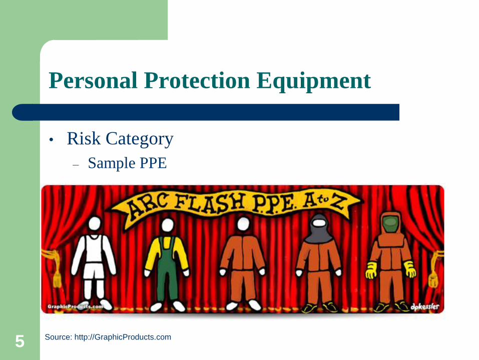
Personal Protection Equipment
• Risk Category
– Sample PPE
Source: http://GraphicProducts.com 5
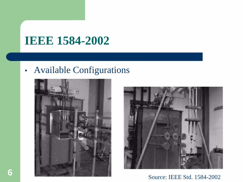
• Available Configurations
Source: IEEE Std. 1584-2002
IEEE 1584-2002
6
Important Factors to be Considered
• Bolted fault current level.
• Duration of the arc.
• Voltage level.
• Electrode Orientation/Configuration (VCB, VCB-
Barrier, HCB, VOA, HOA).
• Gap width between electrodes.
• Calorimeter arrangement and measurement locations.
• Distance between electrode and back panel*.
• Dimensions of the metal enclosure**.
7
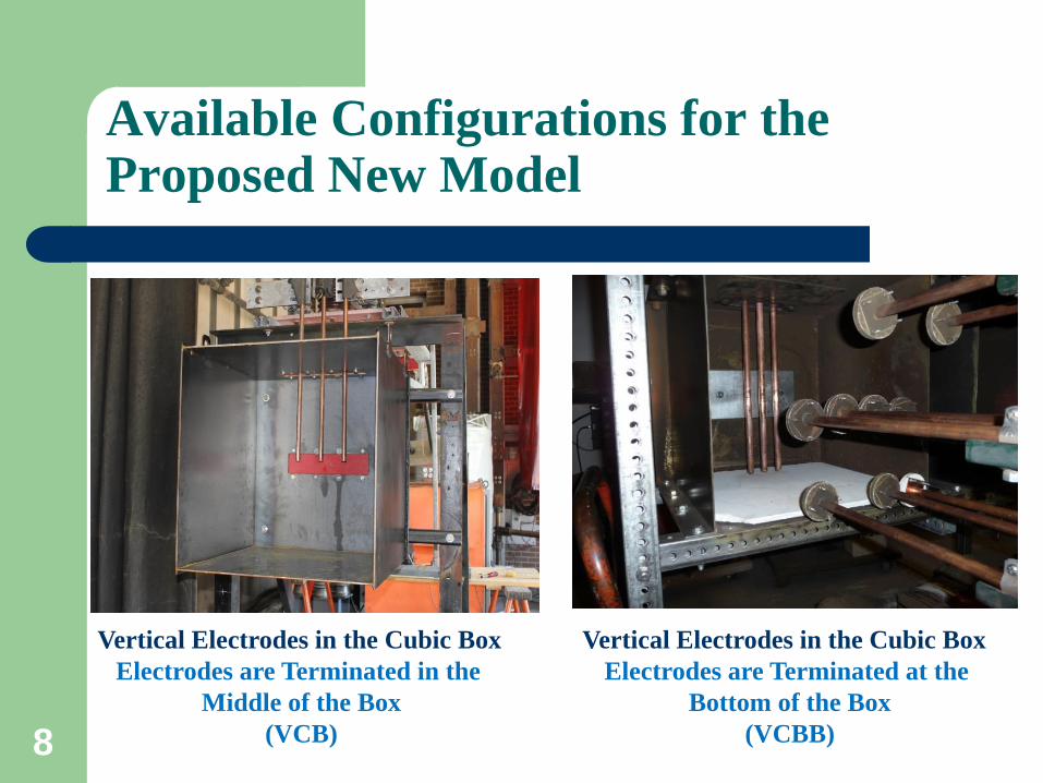
Available Configurations for the Proposed New Model
Vertical Electrodes in the Cubic Box
Electrodes are Terminated in the
Middle of the Box
(VCB)
Vertical Electrodes in the Cubic Box
Electrodes are Terminated at the
Bottom of the Box
(VCBB) 8
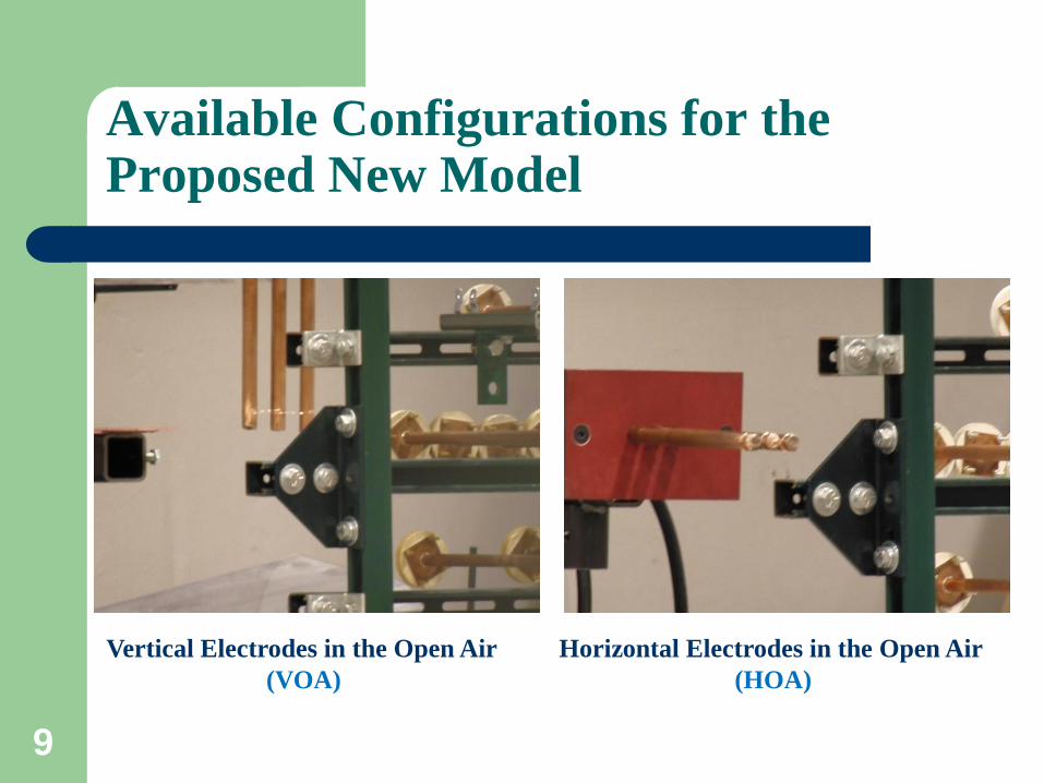
Vertical Electrodes in the Open Air
(VOA)
Horizontal Electrodes in the Open Air
(HOA)
9
Available Configurations for the Proposed New Model
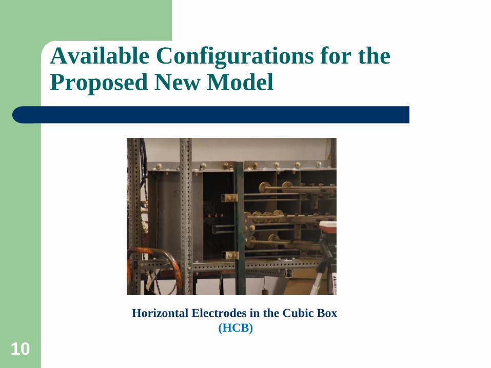
Horizontal Electrodes in the Cubic Box
(HCB)
10
Available Configurations for the Proposed New Model
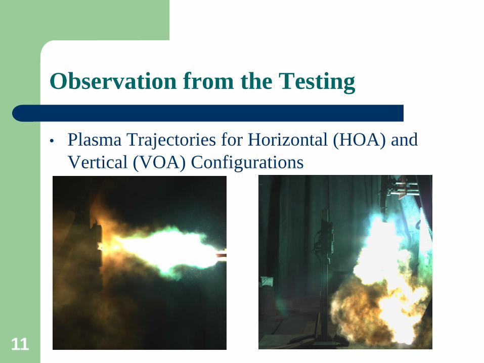
Observation from the Testing
• Plasma Trajectories for Horizontal (HOA) and
Vertical (VOA) Configurations
11
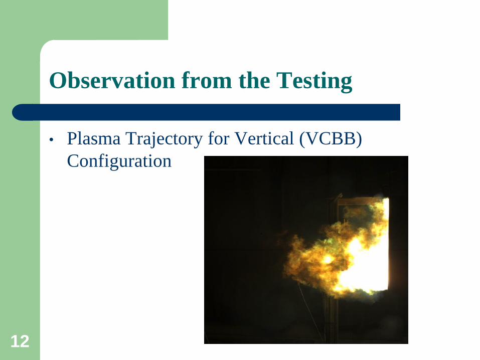
Observation from the Testing
• Plasma Trajectory for Vertical (VCBB)
Configuration
12
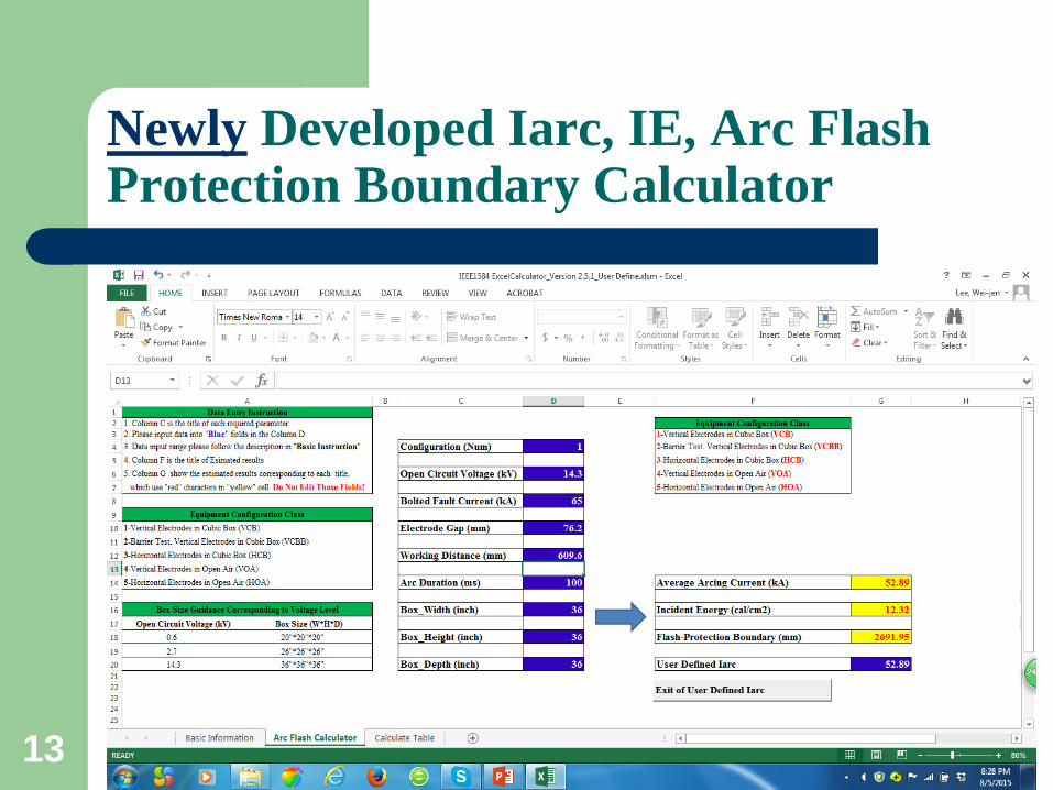
Newly Developed Iarc, IE, Arc Flash Protection Boundary Calculator
13
Non-Thermal Related Hazards
14
Sound
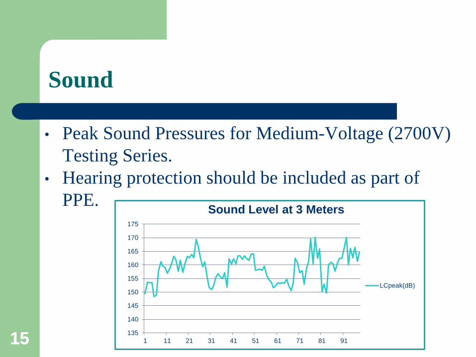
• Peak Sound Pressures for Medium-Voltage (2700V)
Testing Series.
• Hearing protection should be included as part of
PPE.
15 135
140
145
150
155
160
165
170
175
1 11 21 31 41 51 61 71 81 91
Sound Level at 3 Meters
LCpeak(dB)
15
Light
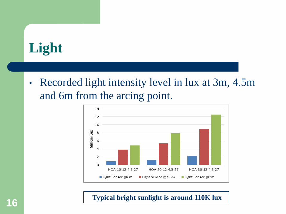
• Recorded light intensity level in lux at 3m, 4.5m
and 6m from the arcing point.
Typical bright sunlight is around 110K lux 16
Pressure
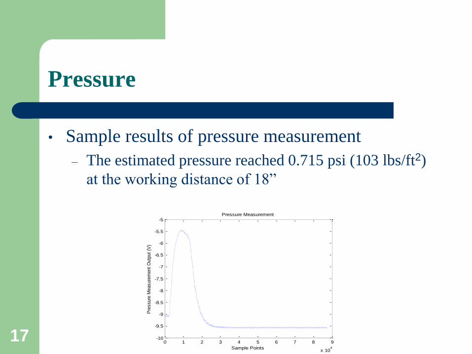
• Sample results of pressure measurement
– The estimated pressure reached 0.715 psi (103 lbs/ft2)
at the working distance of 18”
0 1 2 3 4 5 6 7 8 9
x 104
-10
-9.5
-9
-8.5
-8
-7.5
-7
-6.5
-6
-5.5
-5
Sample Points
Pre
ssure
Measure
ment
Outp
ut
(V)
Pressure Measurement
17
Something That Calorimeter Can Not Measure
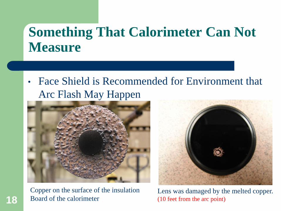
• Face Shield is Recommended for Environment that
Arc Flash May Happen
Lens was damaged by the melted copper. (10 feet from the arc point)
Copper on the surface of the insulation
Board of the calorimeter 18
Simulation of DC Arc Flash
19
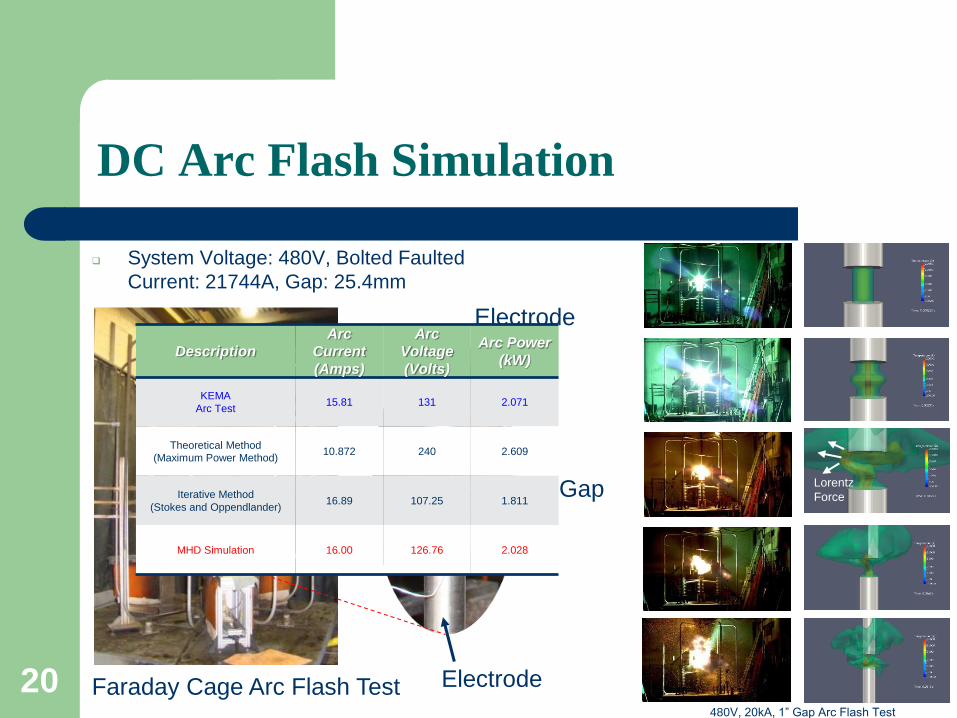
System Voltage: 480V, Bolted Faulted
Current: 21744A, Gap: 25.4mm
Faraday Cage Arc Flash Test
Electrode
Electrode
Gap Lorentz
Force
480V, 20kA, 1” Gap Arc Flash Test
Description
Arc
Current
(Amps)
Arc
Voltage
(Volts)
Arc Power
(kW)
KEMA
Arc Test 15.81 131 2.071
Theoretical Method
(Maximum Power Method) 10.872 240 2.609
Iterative Method
(Stokes and Oppendlander) 16.89 107.25 1.811
MHD Simulation 16.00 126.76 2.028
DC Arc Flash Simulation
20

21