Arbeitskreis Hardware - Medieninformatik · Arbeitskreis Hardware Prof. Dr. Michael Rohs, ... •...
36
Arbeitskreis Hardware Prof. Dr. Michael Rohs, Dipl.-Inform. Sven Kratz [email protected] MHCI Lab, LMU München
Transcript of Arbeitskreis Hardware - Medieninformatik · Arbeitskreis Hardware Prof. Dr. Michael Rohs, ... •...
Arbeitskreis Hardware
Prof. Dr. Michael Rohs, Dipl.-Inform. Sven Kratz [email protected]
MHCI Lab, LMU München
Arbeitskreis Hardware 2 Michael Rohs, LMU München
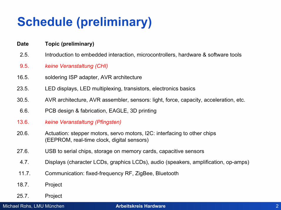
Schedule (preliminary) Date Topic (preliminary)
2.5. Introduction to embedded interaction, microcontrollers, hardware & software tools
9.5. keine Veranstaltung (CHI)
16.5. soldering ISP adapter, AVR architecture
23.5. LED displays, LED multiplexing, transistors, electronics basics
30.5. AVR architecture, AVR assembler, sensors: light, force, capacity, acceleration, etc.
6.6. PCB design & fabrication, EAGLE, 3D printing
13.6. keine Veranstaltung (Pfingsten)
20.6. Actuation: stepper motors, servo motors, I2C: interfacing to other chips (EEPROM, real-time clock, digital sensors)
27.6. USB to serial chips, storage on memory cards, capacitive sensors
4.7. Displays (character LCDs, graphics LCDs), audio (speakers, amplification, op-amps)
11.7. Communication: fixed-frequency RF, ZigBee, Bluetooth
18.7. Project
25.7. Project

Arbeitskreis Hardware 3 Michael Rohs, LMU München
SERVO MOTORS
Arbeitskreis Hardware 4 Michael Rohs, LMU München
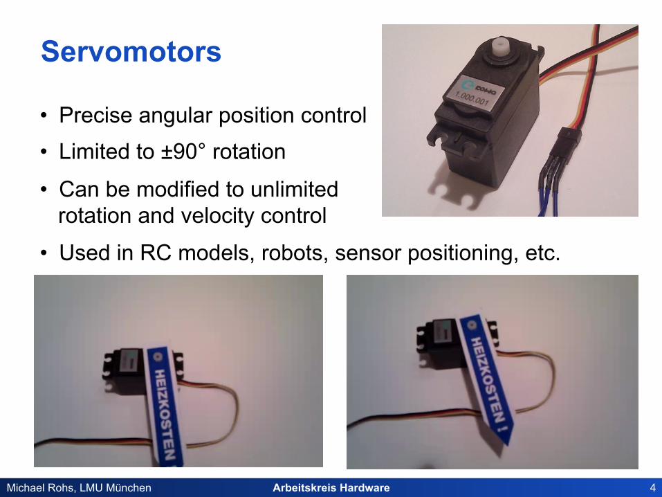
Servomotors
• Precise angular position control • Limited to ±90° rotation
• Can be modified to unlimited rotation and velocity control
• Used in RC models, robots, sensor positioning, etc.
Arbeitskreis Hardware 5 Michael Rohs, LMU München
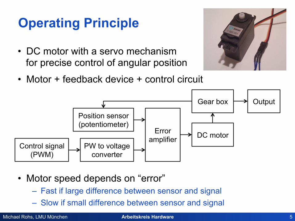
Operating Principle
• DC motor with a servo mechanism for precise control of angular position
• Motor + feedback device + control circuit
• Motor speed depends on “error” – Fast if large difference between sensor and signal – Slow if small difference between sensor and signal
DC motor
Gear box Output
Error amplifier
Control signal (PWM)
PW to voltage converter
Position sensor (potentiometer)

Arbeitskreis Hardware 6 Michael Rohs, LMU München
Controlling Servo Motors
• Wiring: red, black, yellow cables – red = VCC (4.8-6V), black = GND, yellow = PWM signal
• PWM signal: 1.5ms is always neutral, min/max times and positions may vary
1.0ms
20-30ms
1.5ms
2.0ms
0°
-90° +90°
0°
-90° +90°
0°
-90° +90°
neutral position
Arbeitskreis Hardware 7 Michael Rohs, LMU München
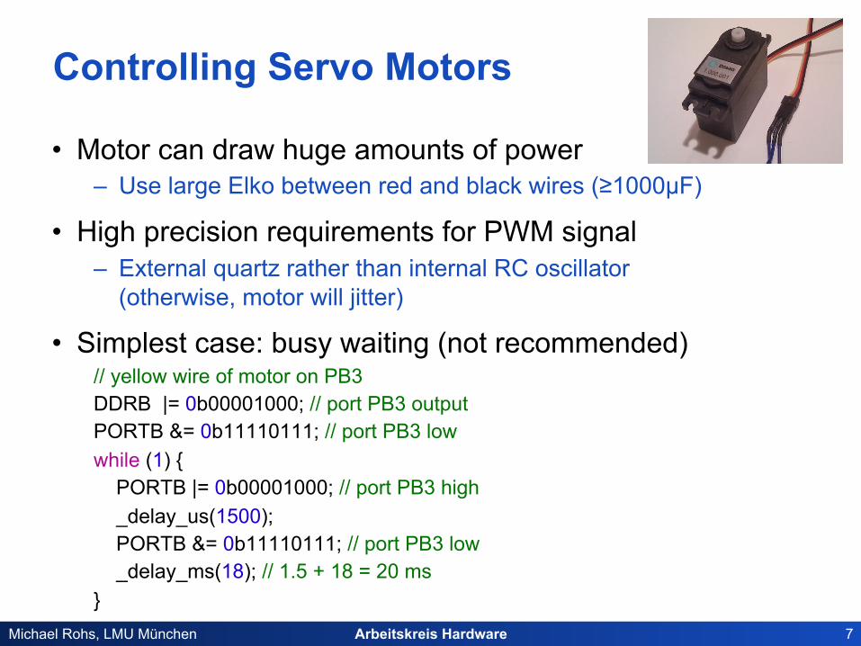
Controlling Servo Motors
• Motor can draw huge amounts of power – Use large Elko between red and black wires (≥1000µF)
• High precision requirements for PWM signal – External quartz rather than internal RC oscillator
(otherwise, motor will jitter)
• Simplest case: busy waiting (not recommended) // yellow wire of motor on PB3 DDRB |= 0b00001000; // port PB3 output PORTB &= 0b11110111; // port PB3 low while (1) { PORTB |= 0b00001000; // port PB3 high _delay_us(1500); PORTB &= 0b11110111; // port PB3 low _delay_ms(18); // 1.5 + 18 = 20 ms }

Arbeitskreis Hardware 8 Michael Rohs, LMU München
Controlling Servo Motors
• Timer-generated PWM signal – Problem, long gaps (20-30ms) between signals (1-2ms) – For 8-bit timers (e.g. ATtiny45) this results in very low resolution:
20ms = 256 counts ó 1ms = 13 counts = -90°, 2ms = 26 counts = +90° ó resolution = 180°/14 counts = 13°
• Solution: 16-bit timers – For 16-bit timers (e.g. ATmega8) resolution is better:
20ms = 65536 counts ó 1ms = 3277 counts = -90°, 2ms = 6554 counts = +90° ó resolution = 180°/3278 counts = 0.05°
• Solution: Combine PWM with timer interrupts – Use shorter timer period to optimally use 1-2ms – Deactivate signal generation (but not timer) during gaps – Tradeoff between interrupt rate and angular resolution
Arbeitskreis Hardware 9 Michael Rohs, LMU München
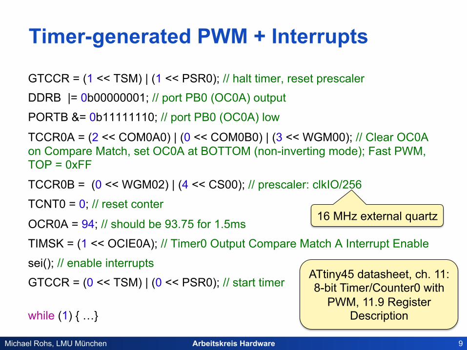
Timer-generated PWM + Interrupts
GTCCR = (1 << TSM) | (1 << PSR0); // halt timer, reset prescaler DDRB |= 0b00000001; // port PB0 (OC0A) output
PORTB &= 0b11111110; // port PB0 (OC0A) low
TCCR0A = (2 << COM0A0) | (0 << COM0B0) | (3 << WGM00); // Clear OC0A on Compare Match, set OC0A at BOTTOM (non-inverting mode); Fast PWM, TOP = 0xFF
TCCR0B = (0 << WGM02) | (4 << CS00); // prescaler: clkIO/256
TCNT0 = 0; // reset conter
OCR0A = 94; // should be 93.75 for 1.5ms
TIMSK = (1 << OCIE0A); // Timer0 Output Compare Match A Interrupt Enable
sei(); // enable interrupts
GTCCR = (0 << TSM) | (0 << PSR0); // start timer
while (1) { …}
16 MHz external quartz
ATtiny45 datasheet, ch. 11: 8-bit Timer/Counter0 with
PWM, 11.9 Register Description

Arbeitskreis Hardware 10 Michael Rohs, LMU München
Timer-generated PWM + Interrupts
#include <avr/interrupt.h> int interruptCount = 0;
ISR(TIMER0_COMPA_vect) // interrupts occur at a frequency of 244.14Hz
{
interruptCount++;
if (interruptCount == 1) { // switch off OC0A output
// Normal port operation, OC0A/OC0B disconnected; Fast PWM
TCCR0A = (0 << COM0A0) | (0 << COM0B0) | (3 << WGM00); } else if (interruptCount >= 5) { // produce OC0A output // Clear OC0A on Compare Match, set OC0A at BOTTOM; Fast PWM
TCCR0A = (2 << COM0A0) | (0 << COM0B0) | (3 << WGM00);
interruptCount = 0;
}
// set OCR0A: 63 = -90°, …, 94 = 0°, …, 125 = +90° (2.9° resolution) }
16 MHz external quartz, prescaler 256, 256 counts
Arbeitskreis Hardware 11 Michael Rohs, LMU München
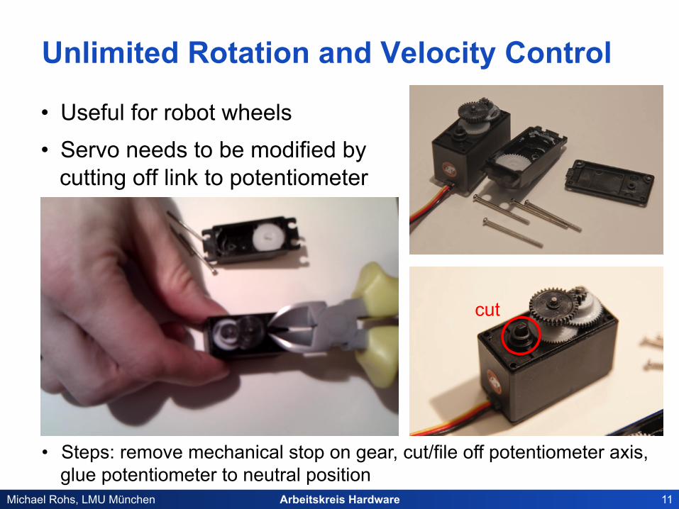
Unlimited Rotation and Velocity Control
• Useful for robot wheels • Servo needs to be modified by
cutting off link to potentiometer
cut
• Steps: remove mechanical stop on gear, cut/file off potentiometer axis, glue potentiometer to neutral position

Arbeitskreis Hardware 12 Michael Rohs, LMU München
STEPPER MOTORS
Arbeitskreis Hardware 13 Michael Rohs, LMU München
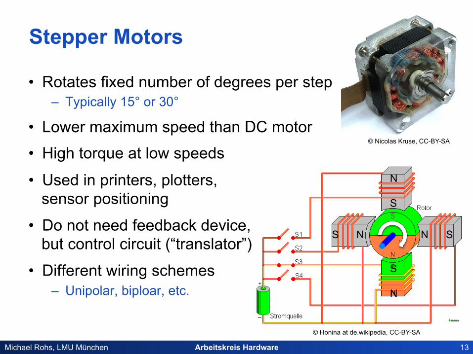
Stepper Motors
• Rotates fixed number of degrees per step – Typically 15° or 30°
• Lower maximum speed than DC motor
• High torque at low speeds
• Used in printers, plotters, sensor positioning
• Do not need feedback device, but control circuit (“translator”)
• Different wiring schemes – Unipolar, biploar, etc.
© Nicolas Kruse, CC-BY-SA
© Honina at de.wikipedia, CC-BY-SA
N S
S N N S
S N
Arbeitskreis Hardware 14 Michael Rohs, LMU München
SENSORS (CONTINUED)
Arbeitskreis Hardware 15 Michael Rohs, LMU München
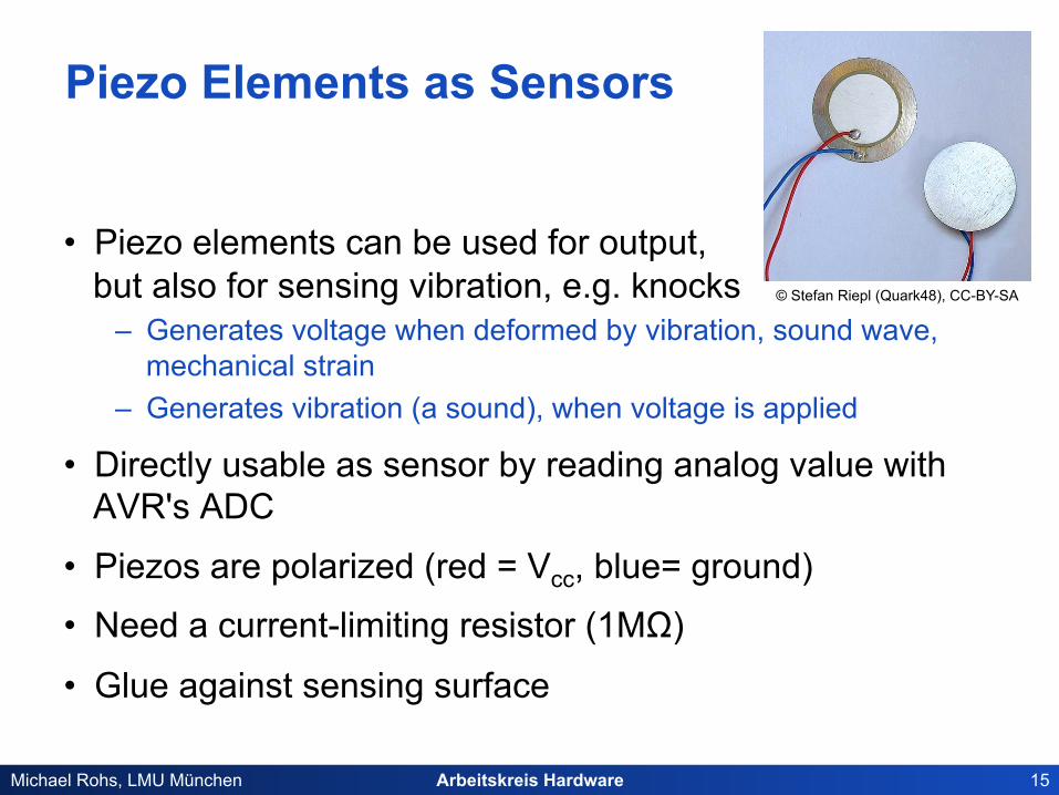
Piezo Elements as Sensors
• Piezo elements can be used for output, but also for sensing vibration, e.g. knocks
– Generates voltage when deformed by vibration, sound wave, mechanical strain
– Generates vibration (a sound), when voltage is applied
• Directly usable as sensor by reading analog value with AVR's ADC
• Piezos are polarized (red = Vcc, blue= ground)
• Need a current-limiting resistor (1MΩ)
• Glue against sensing surface
© Stefan Riepl (Quark48), CC-BY-SA
Arbeitskreis Hardware 16 Michael Rohs, LMU München
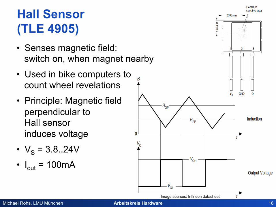
Hall Sensor (TLE 4905) • Senses magnetic field:
switch on, when magnet nearby
• Used in bike computers to count wheel revelations
• Principle: Magnetic field perpendicular to Hall sensor induces voltage
• VS = 3.8..24V
• Iout = 100mA
Image sources: Infineon datasheet
Arbeitskreis Hardware 17 Michael Rohs, LMU München
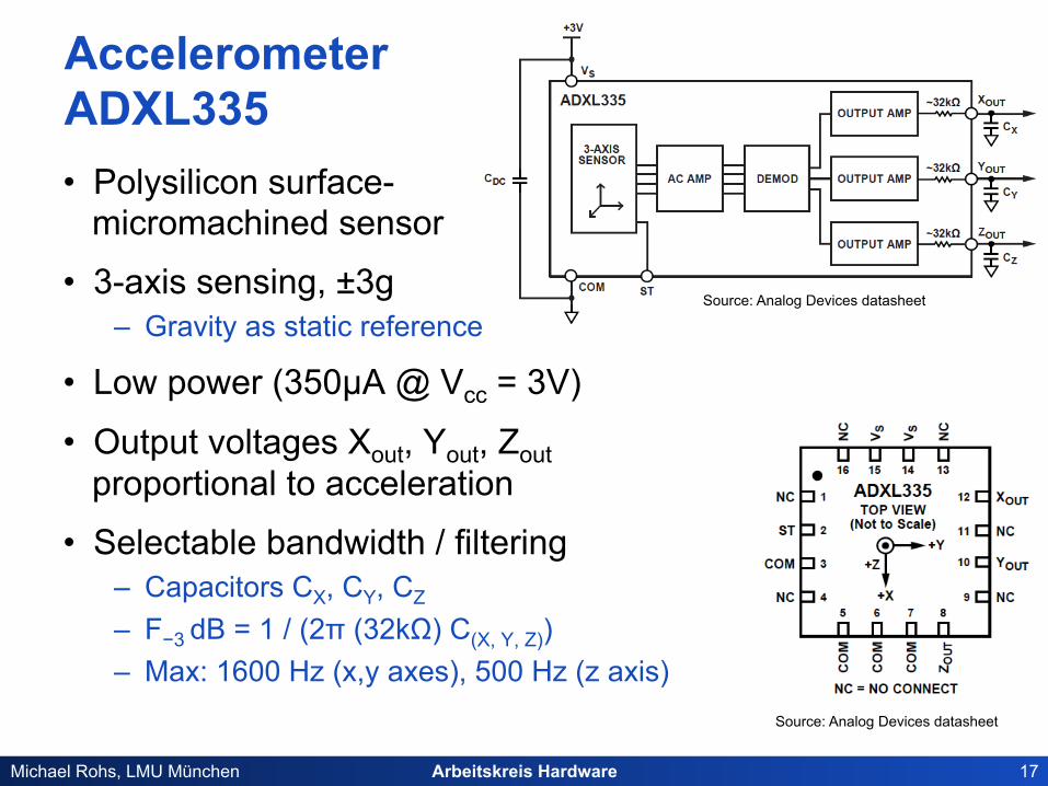
Accelerometer ADXL335 • Polysilicon surface-
micromachined sensor
• 3-axis sensing, ±3g – Gravity as static reference
• Low power (350µA @ Vcc = 3V)
• Output voltages Xout, Yout, Zout proportional to acceleration
• Selectable bandwidth / filtering – Capacitors CX, CY, CZ
– F−3 dB = 1 / (2π (32kΩ) C(X, Y, Z)) – Max: 1600 Hz (x,y axes), 500 Hz (z axis)
Source: Analog Devices datasheet
Source: Analog Devices datasheet
Arbeitskreis Hardware 18 Michael Rohs, LMU München
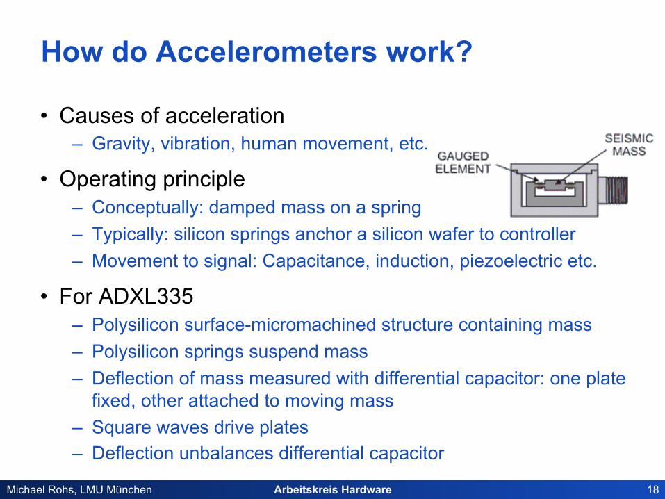
How do Accelerometers work?
• Causes of acceleration – Gravity, vibration, human movement, etc.
• Operating principle – Conceptually: damped mass on a spring – Typically: silicon springs anchor a silicon wafer to controller – Movement to signal: Capacitance, induction, piezoelectric etc.
• For ADXL335 – Polysilicon surface-micromachined structure containing mass – Polysilicon springs suspend mass – Deflection of mass measured with differential capacitor: one plate
fixed, other attached to moving mass – Square waves drive plates – Deflection unbalances differential capacitor

Arbeitskreis Hardware 19 Michael Rohs, LMU München
Gyroscope IDG500 • Dual-axis angular rate sensor (gyroscope)
– Senses rate of rotation about X- and Y-axis (in-plane sensing) – Factory-calibrated – Low-pass filters
• VCC = 3V
• Output voltage proportional to the angular rate
• Separate outputs for standard and high sensitivity – X-/Y-Out Pins: 500°/s full scale range, 2.0mV/°/s sensitivity – X/Y4.5-Out Pins: 110°/s full scale range, 9.1mV/°/s sensitivity
Source: InvenSense datasheet
Source: InvenSense datasheet

Arbeitskreis Hardware 20 Michael Rohs, LMU München
I2C Magnetometer / Compass Honeywell HMC6352 • Compass module
– 2-axis magneto-resistive sensors – Support circuits – Algorithms for heading computation
• Parameters – VCC = 2.7..5.2V, typ. 3.0V – Update rate: 1..20Hz – Heading resolution: 0.5° – I2C interface
Source: Honeywell datasheet
Source: Honeywell datasheet
used for complex sensors (e.g., allows sending
configuration commands)

Arbeitskreis Hardware 21 Michael Rohs, LMU München
Sparkfun Sensors
• Many more sensors… • http://www.sparkfun.com/categories/23?page=all

Arbeitskreis Hardware 22 Michael Rohs, LMU München
INTERFACING HARDWARE
Arbeitskreis Hardware 23 Michael Rohs, LMU München
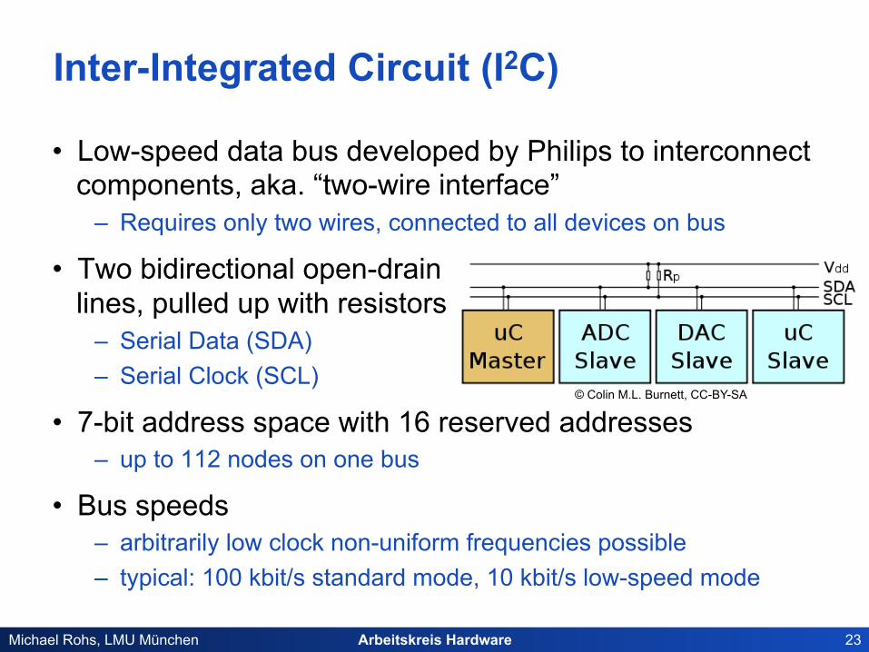
Inter-Integrated Circuit (I2C)
• Low-speed data bus developed by Philips to interconnect components, aka. “two-wire interface”
– Requires only two wires, connected to all devices on bus
• Two bidirectional open-drain lines, pulled up with resistors
– Serial Data (SDA) – Serial Clock (SCL)
• 7-bit address space with 16 reserved addresses – up to 112 nodes on one bus
• Bus speeds – arbitrarily low clock non-uniform frequencies possible – typical: 100 kbit/s standard mode, 10 kbit/s low-speed mode
© Colin M.L. Burnett, CC-BY-SA
Arbeitskreis Hardware 24 Michael Rohs, LMU München
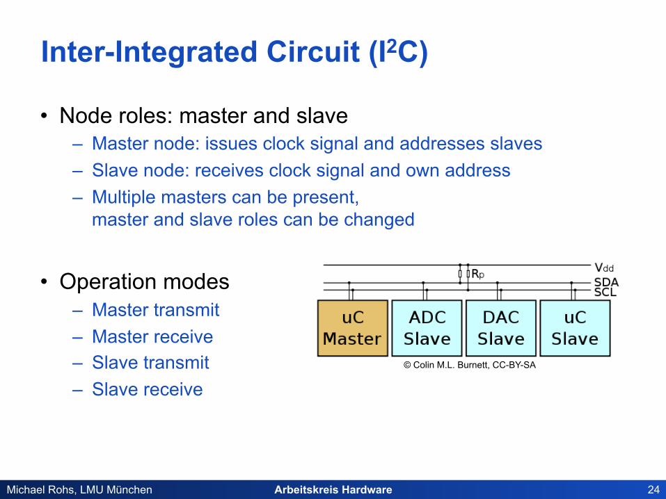
Inter-Integrated Circuit (I2C)
• Node roles: master and slave – Master node: issues clock signal and addresses slaves – Slave node: receives clock signal and own address – Multiple masters can be present,
master and slave roles can be changed
• Operation modes – Master transmit – Master receive – Slave transmit – Slave receive
© Colin M.L. Burnett, CC-BY-SA
Arbeitskreis Hardware 25 Michael Rohs, LMU München
Inter-Integrated Circuit (I2C)
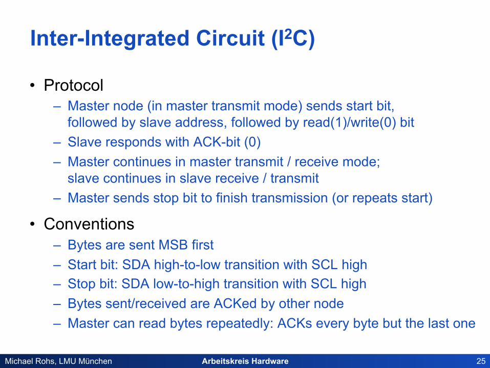
• Protocol – Master node (in master transmit mode) sends start bit,
followed by slave address, followed by read(1)/write(0) bit – Slave responds with ACK-bit (0) – Master continues in master transmit / receive mode;
slave continues in slave receive / transmit – Master sends stop bit to finish transmission (or repeats start)
• Conventions – Bytes are sent MSB first – Start bit: SDA high-to-low transition with SCL high – Stop bit: SDA low-to-high transition with SCL high – Bytes sent/received are ACKed by other node – Master can read bytes repeatedly: ACKs every byte but the last one

Arbeitskreis Hardware 26 Michael Rohs, LMU München
I2C EEPROM 24LC256
• Features – 256 Kbit, VCC = 2.5-5.5V – Max. write current 3mA at 5.5V – Max. read current 400µA at 5.5V – Standby current 100nA – 64-byte pages
• Pins – A0..A2 connected to GND or VCC
– Write protect if WP connected to VCC
– Pullup resistors on SCL, SDA lines: RPU = 10kΩ for SCL 100kHz
Source: Microchip datasheet

Arbeitskreis Hardware 27 Michael Rohs, LMU München
I2C EEPROM 24LC256: Sequence
• Data transfer sequence – SCL and SDA high on inactive bus (pulled up to VCC)
• Acknowledge bit timing
Figure sources: Microchip datasheet
Arbeitskreis Hardware 28 Michael Rohs, LMU München
I2C EEPROM 24LC256: Control Byte
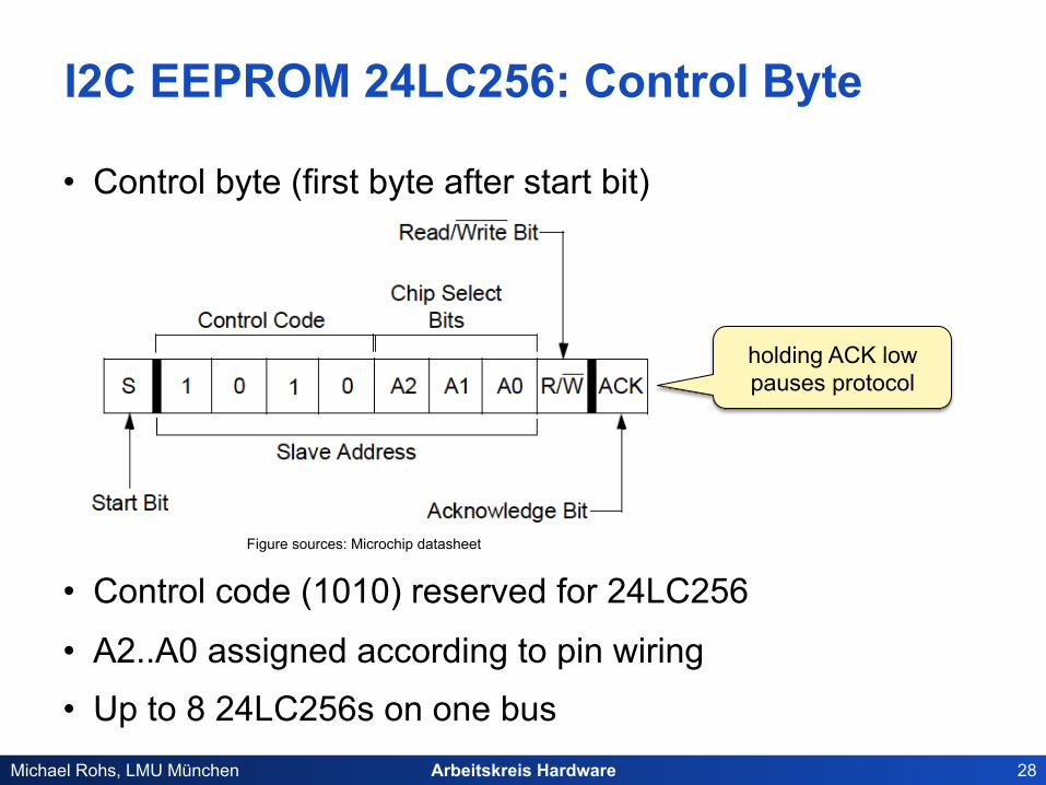
• Control byte (first byte after start bit)
• Control code (1010) reserved for 24LC256
• A2..A0 assigned according to pin wiring
• Up to 8 24LC256s on one bus
Figure sources: Microchip datasheet
holding ACK low pauses protocol

Arbeitskreis Hardware 29 Michael Rohs, LMU München
I2C EEPROM 24LC256: Write
• Byte write
• Page write (up to 64 bytes)
Figure sources: Microchip datasheet
master continues to send more bytes, finally STOP
Arbeitskreis Hardware 30 Michael Rohs, LMU München
I2C EEPROM 24LC256: Read
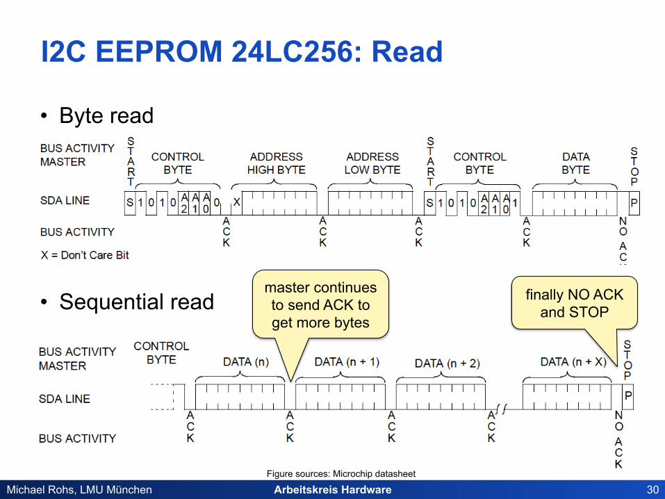
• Byte read
• Sequential read
Figure sources: Microchip datasheet
master continues to send ACK to get more bytes
finally NO ACK and STOP
Arbeitskreis Hardware 31 Michael Rohs, LMU München
Open Drain / Open Collector
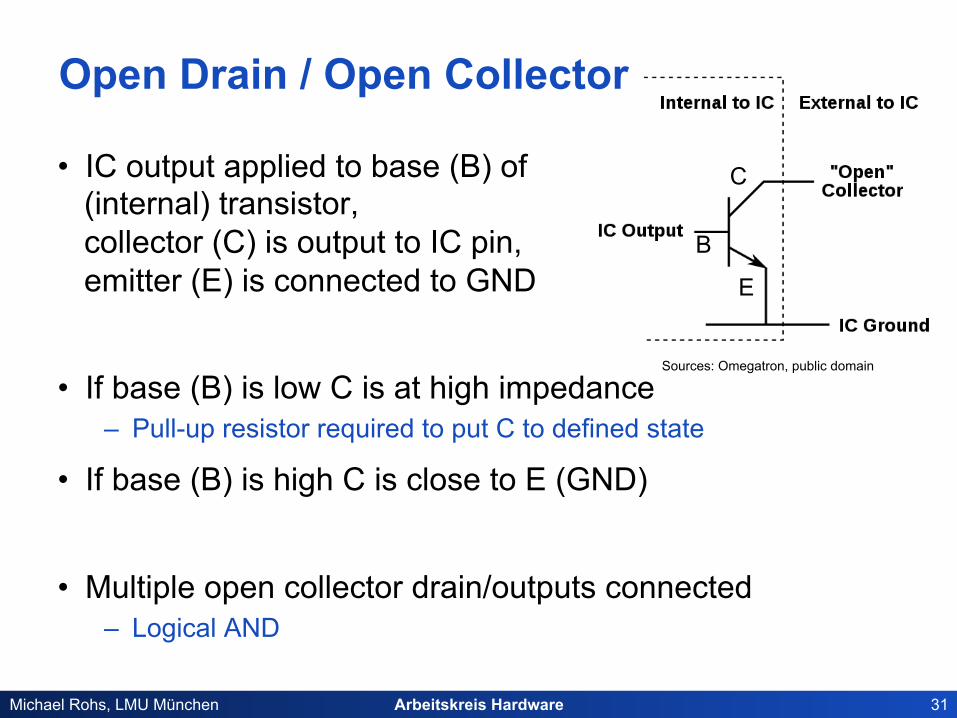
• IC output applied to base (B) of (internal) transistor, collector (C) is output to IC pin, emitter (E) is connected to GND
• If base (B) is low C is at high impedance – Pull-up resistor required to put C to defined state
• If base (B) is high C is close to E (GND)
• Multiple open collector drain/outputs connected – Logical AND
Sources: Omegatron, public domain
B
C
E
Arbeitskreis Hardware 32 Michael Rohs, LMU München
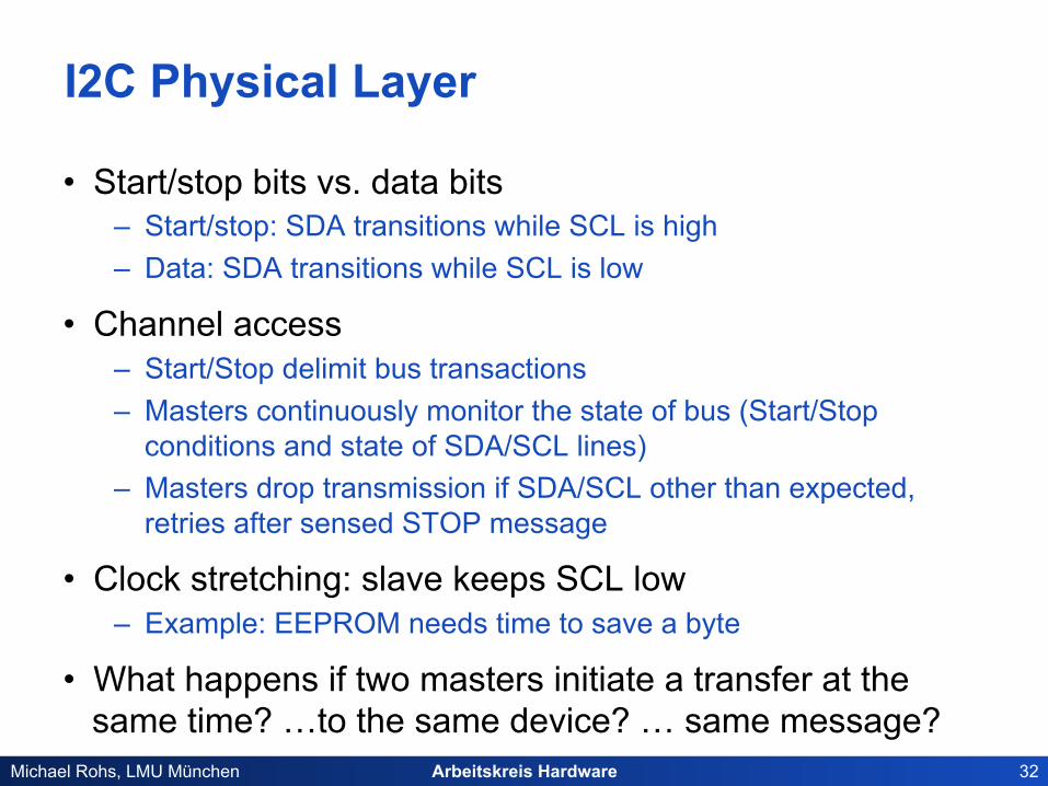
I2C Physical Layer
• Start/stop bits vs. data bits – Start/stop: SDA transitions while SCL is high – Data: SDA transitions while SCL is low
• Channel access – Start/Stop delimit bus transactions – Masters continuously monitor the state of bus (Start/Stop
conditions and state of SDA/SCL lines) – Masters drop transmission if SDA/SCL other than expected,
retries after sensed STOP message
• Clock stretching: slave keeps SCL low – Example: EEPROM needs time to save a byte
• What happens if two masters initiate a transfer at the same time? …to the same device? … same message?

Arbeitskreis Hardware 33 Michael Rohs, LMU München
Real-Time Clock DS1307 with I2C interface • Highly stable time/date, battery buffered
– Clock/calendar: provides seconds, minutes, hours, day, date, month, and year information
– Leap year handling, 12-/24-hour format – Power-sense circuit to switch to backup supply – 500nA in Backup Mode (e.g. button cell battery) – Normal operation: 5V
• Useful for long-term sensing applications that need time-/date-stamps
• I2C commands to set/read time/date
Figure sources: MAXIM datasheet
3V
Arbeitskreis Hardware 34 Michael Rohs, LMU München
AVR Universal Serial Interface
• Two-wire interface (I2C) • Three-wire interface (e.g. for programming)
• ATtiny45 and ATmega8, not ATtiny13

Arbeitskreis Hardware 35 Michael Rohs, LMU München
Universal Serial Interface: I2C, TWI
Source: Atmel Datasheet
Arbeitskreis Hardware 36 Michael Rohs, LMU München
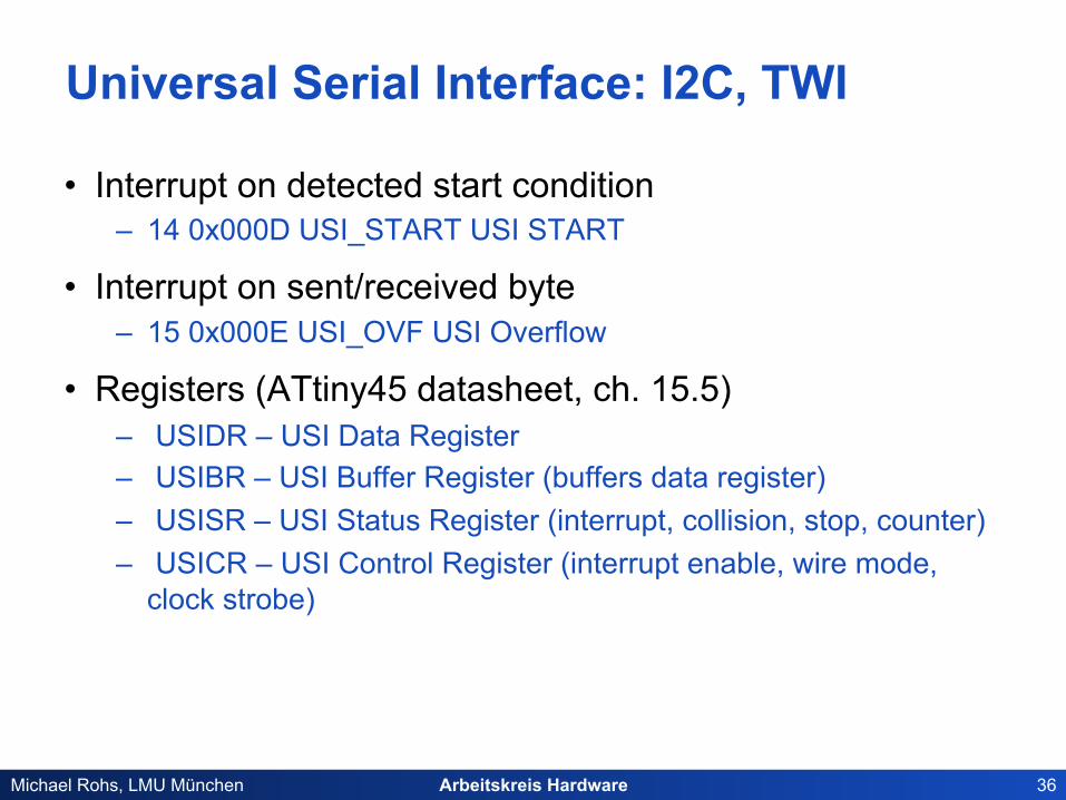
Universal Serial Interface: I2C, TWI
• Interrupt on detected start condition – 14 0x000D USI_START USI START
• Interrupt on sent/received byte – 15 0x000E USI_OVF USI Overflow
• Registers (ATtiny45 datasheet, ch. 15.5) – USIDR – USI Data Register – USIBR – USI Buffer Register (buffers data register) – USISR – USI Status Register (interrupt, collision, stop, counter) – USICR – USI Control Register (interrupt enable, wire mode,
clock strobe)