AR-15 Jig Instructions Jig Instructions ver 1.1j.pdfFor the first time user, the Modulus Arms jig...
24
AR-308/AR-10 Jig Instructions
Transcript of AR-15 Jig Instructions Jig Instructions ver 1.1j.pdfFor the first time user, the Modulus Arms jig...

AR-308/AR-10 Jig Instructions
www.ModulusArms.com October 20, 2014
www.ModulusArms.com | AR-308 Jig Instructions 2
Introduction
If your lower can accommodate an AR-308 upper, it is compatible with the Modulus Arms 80% AR-308
Lower Receiver Jig. The Modulus Arms jig utilizes the same standardized lower features designed to
center an AR-308 upper to properly locate the features that need to be fabricated, resulting in a
universal fit. A billet lower completed with the Modulus Arms 80% jig using basic hand-held power tools
is shown below.
For the first time user, the Modulus Arms jig offers increased safety (no milling with a drill press), a
simple and easy to use process, compatibility with commonly available hand-held power tools, and
reduced risk of failure.
For the experienced builder, the Modulus Arms jig offers universal compatibility, increased precision,
and reduced fabrication time. Modulus Arms also offers individual replacement parts which are
available for purchase at www.modulusarms.com.
The lower is easily completed with four straightforward steps to fabricate the: 1) the trigger slot, 2) the
rear shelf pocket, 3) the fire control pocket, and 4) the fire control pin holes (trigger pin, hammer pin,
and safety selector). To reduce the fabrication time and to improve the finish, a router with an end mill
is used to finish the cavity that is first hollowed out with a drill bit in the first three steps.
Once any of the required finishing features are started, the lower is considered a firearm, and all local,
state, and federal firearms laws will apply. It is your responsibility to check the legality of finishing and
owning an 80% lower in your area. Please make sure you are familiar with the safe operation of power
tools before using the Modulus Arms jig to complete your lower.
Modulus Arms Jig Part Description & Key Features
The Modulus Arms 80% Jig kit contains the following parts as shown in figure 1 and listed below:

www.ModulusArms.com October 20, 2014
www.ModulusArms.com | AR-308 Jig Instructions 3
1. Template
2. Side Plate (2x)
3. Drill Guide
4. Front Support
5. Rear Support
6. Buffer Support
7. Depth Gauge
8. Cap Screws [8-32 x ½”] (14x)
9. Side Plate Support Cap Screw [8-32 x 1.5”] (2x)
10. Rear Take Down Cap Screw/Nut/Washer [8-32 x
2.25”]
Figure 1: Modulus Arms Jig Kit Contents (in production kits, short and long screws are the same size)
Unlike conventional 80% jigs, all of the features that require milling with the ¼” end mill are contained
on a single template that is designed to be used in two orientations (figure 2). The fire control pocket is
fabricated in one orientation while the rear shelf pocket and trigger slot are fabricated in the other
orientation. The template is attached to the front and rear supports allowing for proper centering of the
features. The side plates are attached with the oval holes allowing for a universal fit regardless of
variations in the lower receiver widths.

www.ModulusArms.com October 20, 2014
www.ModulusArms.com | AR-308 Jig Instructions 4
Figure 2: Template Features
To speed up the milling process, excess material is removed with a drill. The drill holes are located with a
drill guide installed under the template as shown in figure 3. Since the template only exposes a limited
number of holes in the drill template, there is no chance to drill a hole in the wrong location.
CAUTION: The drill guide is user friendly, one of the screw holes will not line up if the orientation is
incorrect. Furthermore, the drill guide cannot be installed upside down. For best results, start the drill
with the bit inside of the drill template to reduce the risk of accidental jig template damage.
Figure 3: Drill Guild installed under template in both orientations
The same side plate is used on the left and right side as shown in figure 4. The rear takedown hole is
provided to assure proper placement for the drilling of the safety selector and the trigger group pins.
The side plate support holes are designed to reduce flex and marring with anodized lowers when the
side plates are placed in a vise to secure the lower during the milling process.

www.ModulusArms.com October 20, 2014
www.ModulusArms.com | AR-308 Jig Instructions 5
Figure 4: Side Plate Features
The depth gauge is used for both drilling and milling as shown in figure 5. The gauge is used 1) to set the
drill depth using a drill stop on the 3/8” drill bit and 2) use to set the router depth for each pass and the
final pass. Depth gauge “A” is used to set the end mill so it exits the bottom of the lower for the trigger
hole. Depth gauge “B” is used for the rear shelf (depth = 0.630”). Depth gauge “C” is used for the fire-
control pocket (depth= 1.249”). The 1st hash mark is used to indicate the top surface of the lower. The
distance between the set of hash marks (approx. 1/8”) represents the maximum material that should be
removed for each milling pass. The bottom of the depth gauge is used to indicate the final pass. The user
is encouraged to start at 1/32” - 1/16” depth of cut and work up to a comfortable depth that should not
exceed more than ¼” depth of cut. Typically, a deeper depth of cut requires a router with variable speed
so the end mill speed can be slowed down for more control.

www.ModulusArms.com October 20, 2014
www.ModulusArms.com | AR-308 Jig Instructions 6
Figure 5: Depth gauge used to set the drill depth and end mill depth
The following parts are required to complete the jig and can be purchased as an optional kit: 1. ¼” x 4” 4-flute End mill with 1” Depth of Cut
2. 3/8” Drill Bit (fire-control, rear-shelf, and safety
selector)
3. 19/64” Drill Bit (trigger slot)
4. 5/32” Drill Bit (hammer/trigger pin)
5. 3/8” Drill Stop
Figure 6: Optional kit required to finish the lower
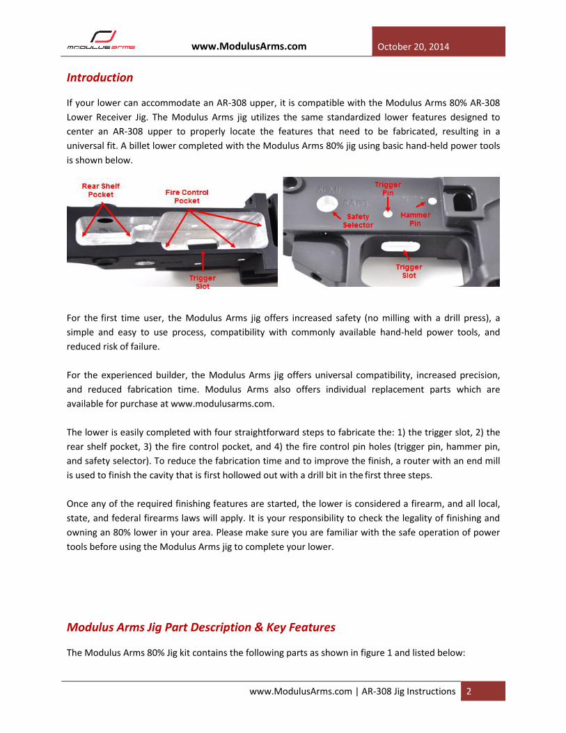
The following tools are required / recommended (examples shown in the figure below): 1. Router (full size or laminate)
2. Drill (hand drill or drill press)
3. Vise (drill press shown)
4. 3/64” Allen Wrench (for drill stop)
5. 3/32” Allen Wrench (8-32 cap screws)
6. Front Take Down (pin, detent, & spring)
7. C-clamp (optional if vise is not mounted)
www.ModulusArms.com October 20, 2014
www.ModulusArms.com | AR-308 Jig Instructions 7
Figure 7: Example of common tools that can be used to complete the lower (AR-15 jig shown)
Modulus Arms Jig: General Assembly Instructions
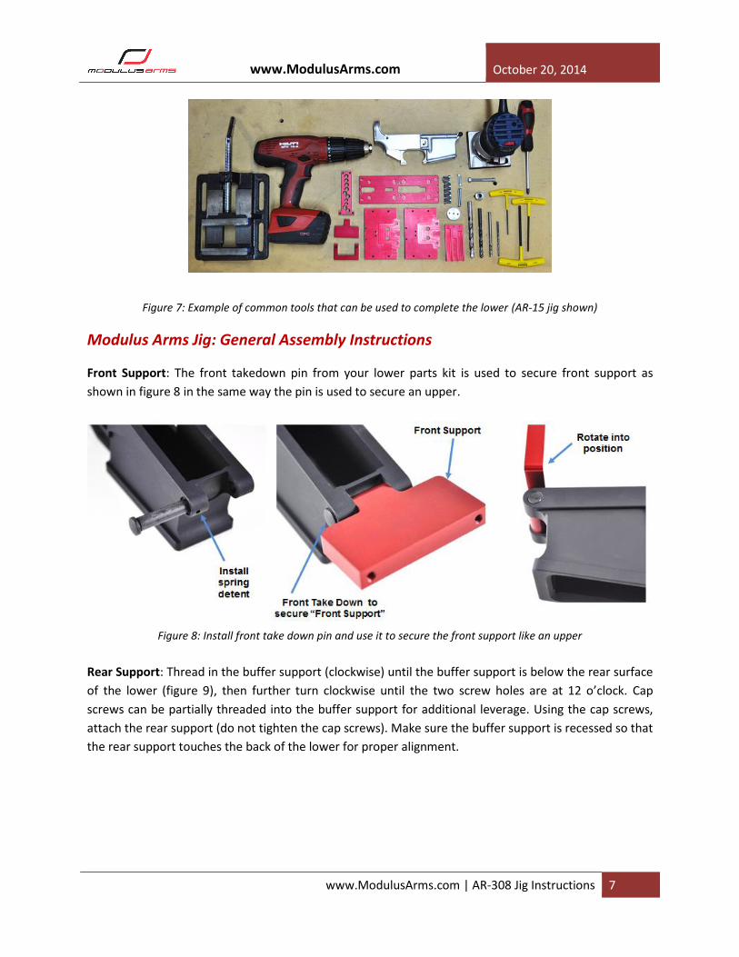
Front Support: The front takedown pin from your lower parts kit is used to secure front support as
shown in figure 8 in the same way the pin is used to secure an upper.
Figure 8: Install front take down pin and use it to secure the front support like an upper
Rear Support: Thread in the buffer support (clockwise) until the buffer support is below the rear surface
of the lower (figure 9), then further turn clockwise until the two screw holes are at 12 o’clock. Cap
screws can be partially threaded into the buffer support for additional leverage. Using the cap screws,
attach the rear support (do not tighten the cap screws). Make sure the buffer support is recessed so that
the rear support touches the back of the lower for proper alignment.

www.ModulusArms.com October 20, 2014
www.ModulusArms.com | AR-308 Jig Instructions 8
Figure 9: Install buffer support and rear support
Template and Drill Guide: The template attaches to the front and rear support using four cap screws.
For milling, the template is used alone (figure 10, left). For roughing, the drill guide is used (figure 10,
right). The first three of four steps involves installing the template with the drill guide to rough out the
pocket, then removing the drill guide to mill the pocket. When properly oriented, the head of all cap
screws should be recessed below the jig template top surface. After the 4 screws that are used to
attached the template to the front and rear support, tighten the two screws that attach the rear support
to the buffer support (figure 9).
Figure 10: Template only (left) or Template & Drill Guide (right) installed
Side Plates: The side plates attach to the jig through the template with four small cap screws (figure 11,
right). The jig is designed to accommodate different lower widths and should be pressed against the
lower before tightening the screws. For the first three steps, the main purpose of the two side plates is
to allow a vise to secure the jig, so the screw through the rear take down hole is not needed. For the
fourth step, the side plates serve as the template for the fire control group pins holes. For increased
accuracy, the rear take down screw/nut can be installed through the rear-take down hole. Unlike the

www.ModulusArms.com October 20, 2014
www.ModulusArms.com | AR-308 Jig Instructions 9
AR-15 design, the nubs on the side plate are designed to go into the rear take down holes in the lower.
The nubs are designed for a tight fit, the screw and nut can be used to snug the side plates against the
lower. The side plate support screws are designed to keep the side plates from flexing when clamped in
a vise. To accomplish this, the side plates are threaded on both sides, please use care when starting the
threads into the second plate.
Figure 11: Side Plate Installation
6061 vs 7075 Lower: Commonly, most forged lowers are made with 7075-T6, and billet can be offered in
either 6061-T6 or 7075-T6. In general, 7075-T6 is more difficult to work with requiring shallower depth
of cuts when using the router. Although a hand drill can be used with 7075-T6, a drill press can
significantly reduce the overall effort. If a hand-drill is used with 7075-T6, please be patient and go slow.
Tool setup: For best results, Modulus Arms recommends that the router and optional drill press is
properly setup to be square. Adjustments, if necessary, should be made before beginning the fabrication
process. If using a hand-drill, care must be taken to drill each hole in a square fashion.
Step 1: Fully Supported Trigger Slot
Configure jig for drilling: The template is installed with the rear-shelf pocket template closest to the
buffer tube mount as shown in figure 1.1 with the drill guide installed under the jig. The trigger slot
should have two drill holes and the rear shelf should have three drill holes as shown.

www.ModulusArms.com October 20, 2014
www.ModulusArms.com | AR-308 Jig Instructions 10
Figure 1.1: Jig configured to drill he rear pocket and trigger slot
Trigger Slot Drilling: With the two exposed holes in the trigger slot, use a 19/64” drill bit to drill all the
way through the lower (figure 1.2, left). Figure 1.2, right shows the lower after completion. For best
results, start the drill after the drill bit is partially or completely through the drill guide to prevent
accidental damage to the template. Make sure the hole is drilled normal (perpendicular in the x and y
direction) to the lower surface.
Figure 1.2: Drilling the trigger slot holes (left), lower after drilling (right)
Configure jig for milling: Remove the rear support and side support screw (6x) and pivot the jig template
up as shown in figure 1.3 (left). Remove the drill template (figure 1.3, middle). Reassemble using the two
rear support and four side plate screws. The properly configured jig is shown in figure 1.3, right.
Figure 1.3: Jig configured to mill the rear pocket and trigger slot

www.ModulusArms.com October 20, 2014
www.ModulusArms.com | AR-308 Jig Instructions 11
Trigger Slot Milling: A router and ¼” end mill is used to fabricate the trigger slot (figure 1.4, left) and the
completed trigger slot is shown in figure 1.5, right.
1. In figure 1.4 (middle) the end mill depth is adjust to the 1st template hash mark. This represents
the top of the lower. The maximum depth of cut is the distance between two hash marks.
Modulus Arms suggests that the user starts below this level and work up to a comfortable depth
of cut that never exceeds the maximum depth of cut.
2. Insert the end mill through the template and into either drill hole formed earlier. Make sure the
end mill does not touch the wall of the drill hole. Carefully turn on the router and allow the
router to come up to full speed.
3. With firm downward pressure applied to the base, mill using shallow clockwise passes with light
pressure. The 1st goal is the make shallow clockwise passes is to first adjoin the two holes. Next,
with light clockwise passes, widen until the end mill touches the side of the template. Turn off
the router, wait until the end mill stops spinning, and remove from the jig. Figure 1.5, left shows
the lower after the first pass.
4. Increase the cutting depth using depth gauge as a guide and repeat steps #2 and #3 until the
end mill breaks out of the bottom of the lower. The “A” depth gauge can be used to set the final
depth as shown in figure 1.4, right.
Figure 1.4: Router to mill out trigger-slot ¼” at a time (left) and final cut depth set with “A” depth gauge
Figure 1.5: Example of partially milled trigger slot (left) and complete trigger slot (right)
www.ModulusArms.com October 20, 2014
www.ModulusArms.com | AR-308 Jig Instructions 12
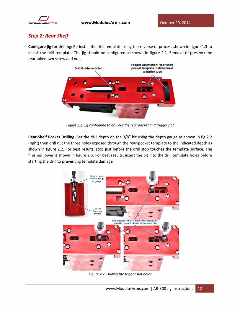
Step 2: Rear Shelf
Configure jig for drilling: Re-install the drill template using the reverse of process shown in figure 1.3 to
install the drill template. The jig should be configured as shown in figure 2.1. Remove (if present) the
rear takedown screw and nut.
Figure 2.1: Jig configured to drill out the rear pocket and trigger slot
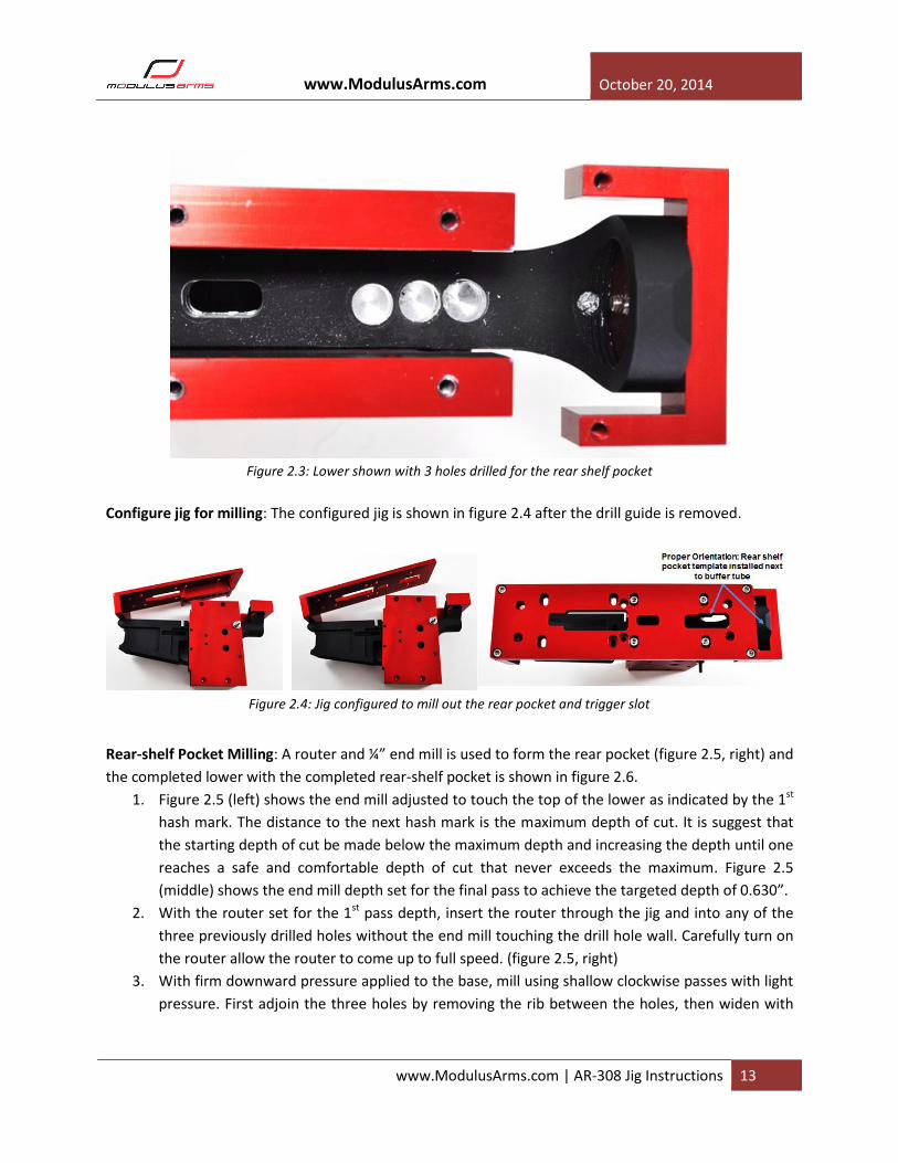
Rear-Shelf Pocket Drilling: Set the drill depth on the 3/8” bit using the depth gauge as shown in fig 2.2
(right) then drill out the three holes exposed through the rear-pocket template to the indicated depth as
shown in figure 2.2. For best results, stop just before the drill stop touches the template surface. The
finished lower is shown in figure 2.3. For best results, insert the bit into the drill template holes before
starting the drill to prevent jig template damage
Figure 2.2: Drilling the trigger slot holes
www.ModulusArms.com October 20, 2014
www.ModulusArms.com | AR-308 Jig Instructions 13
Figure 2.3: Lower shown with 3 holes drilled for the rear shelf pocket
Configure jig for milling: The configured jig is shown in figure 2.4 after the drill guide is removed.
Figure 2.4: Jig configured to mill out the rear pocket and trigger slot
Rear-shelf Pocket Milling: A router and ¼” end mill is used to form the rear pocket (figure 2.5, right) and
the completed lower with the completed rear-shelf pocket is shown in figure 2.6.
1. Figure 2.5 (left) shows the end mill adjusted to touch the top of the lower as indicated by the 1st
hash mark. The distance to the next hash mark is the maximum depth of cut. It is suggest that
the starting depth of cut be made below the maximum depth and increasing the depth until one
reaches a safe and comfortable depth of cut that never exceeds the maximum. Figure 2.5
(middle) shows the end mill depth set for the final pass to achieve the targeted depth of 0.630”.
2. With the router set for the 1st pass depth, insert the router through the jig and into any of the
three previously drilled holes without the end mill touching the drill hole wall. Carefully turn on
the router allow the router to come up to full speed. (figure 2.5, right)
3. With firm downward pressure applied to the base, mill using shallow clockwise passes with light
pressure. First adjoin the three holes by removing the rib between the holes, then widen with

www.ModulusArms.com October 20, 2014
www.ModulusArms.com | AR-308 Jig Instructions 14
shallow clockwise passes until the end mill touches the side of the template. Turn off the router,
wait until the end mill stops spinning, and remove from the jig.
4. Check the depth using the “B” depth gauge after each pass to make sure that the collet is tight
and the end mill is not pulling out. Repeat steps 2 and 3 with the end mill increment by the
desired depth of cut (not to exceed the maximum) until the final end mill depth shown in figure
2.5 (middle) is reached.
5. Figure 2.6 shows the lower before the 1st pass (top left), after the 1st pass (top right), after
several passes (bottom left), and after the final pass with the jig template removed (bottom
right)
Figure 2.5: Milling the rear-shelf pocket (left) “B” depth gauge at the maximum depth for a 0.630” rear pocket
Figure 2.6: Finished rear-shelf pocket

www.ModulusArms.com October 20, 2014
www.ModulusArms.com | AR-308 Jig Instructions 15
Step 3: Fire-Control Pocket
Configure jig for drilling: The template is installed with the fire-control pocket template closest to the
buffer as shown in figure 3.1 with the drill guide installed as shown. If the holes for the drill template
does not line up, it’s likely that the drill guide is orientated in the wrong direction.
Figure 3.1: Jig configured to drill the fire-control pocket
Fire-Control Pocket Drilling: The four holes exposed through the rear-pocket template are drilled out
with a 3/8” drill bit (figure 3.2, right) to a depth set with the “C” depth gauge (figure 2.2, right). Finished
lower is shown in figure 3.3.
Figure 3.2: Drilling the Fire-Control Pocket Holes
www.ModulusArms.com October 20, 2014
www.ModulusArms.com | AR-308 Jig Instructions 16
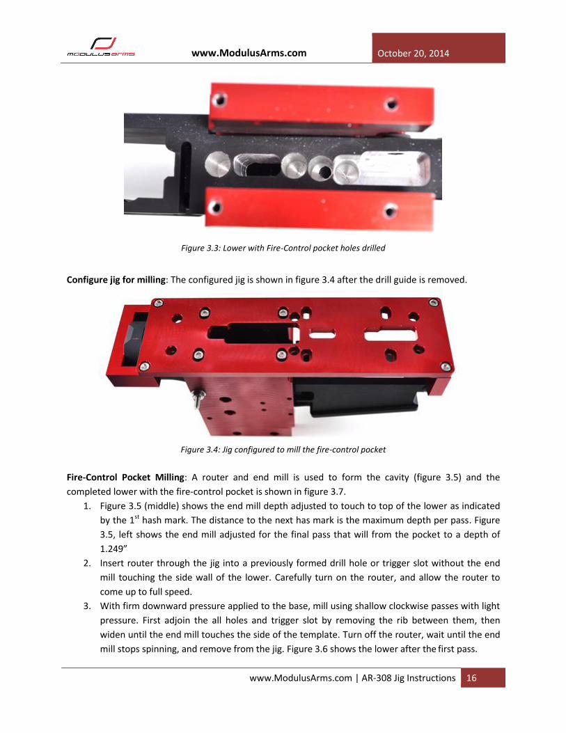
Figure 3.3: Lower with Fire-Control pocket holes drilled
Configure jig for milling: The configured jig is shown in figure 3.4 after the drill guide is removed.
Figure 3.4: Jig configured to mill the fire-control pocket
Fire-Control Pocket Milling: A router and end mill is used to form the cavity (figure 3.5) and the
completed lower with the fire-control pocket is shown in figure 3.7.
1. Figure 3.5 (middle) shows the end mill depth adjusted to touch to top of the lower as indicated
by the 1st hash mark. The distance to the next has mark is the maximum depth per pass. Figure
3.5, left shows the end mill adjusted for the final pass that will from the pocket to a depth of
1.249”
2. Insert router through the jig into a previously formed drill hole or trigger slot without the end
mill touching the side wall of the lower. Carefully turn on the router, and allow the router to
come up to full speed.
3. With firm downward pressure applied to the base, mill using shallow clockwise passes with light
pressure. First adjoin the all holes and trigger slot by removing the rib between them, then
widen until the end mill touches the side of the template. Turn off the router, wait until the end
mill stops spinning, and remove from the jig. Figure 3.6 shows the lower after the first pass.
www.ModulusArms.com October 20, 2014
www.ModulusArms.com | AR-308 Jig Instructions 17
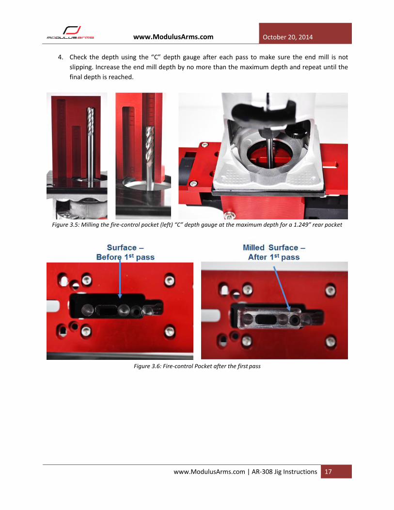
4. Check the depth using the “C” depth gauge after each pass to make sure the end mill is not
slipping. Increase the end mill depth by no more than the maximum depth and repeat until the
final depth is reached.
Figure 3.5: Milling the fire-control pocket (left) “C” depth gauge at the maximum depth for a 1.249” rear pocket
Figure 3.6: Fire-control Pocket after the first
pass
www.ModulusArms.com October 20, 2014
www.ModulusArms.com | AR-308 Jig Instructions 18
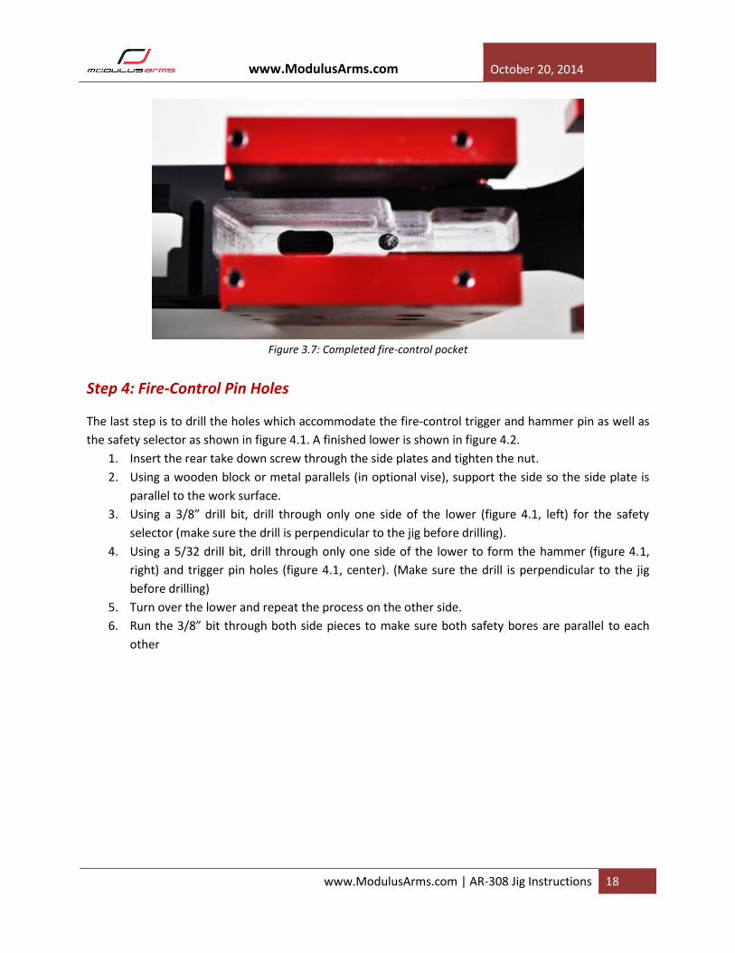
Figure 3.7: Completed fire-control pocket
Step 4: Fire-Control Pin Holes
The last step is to drill the holes which accommodate the fire-control trigger and hammer pin as well as
the safety selector as shown in figure 4.1. A finished lower is shown in figure 4.2.
1. Insert the rear take down screw through the side plates and tighten the nut.
2. Using a wooden block or metal parallels (in optional vise), support the side so the side plate is
parallel to the work surface.
3. Using a 3/8” drill bit, drill through only one side of the lower (figure 4.1, left) for the safety
selector (make sure the drill is perpendicular to the jig before drilling).
4. Using a 5/32 drill bit, drill through only one side of the lower to form the hammer (figure 4.1,
right) and trigger pin holes (figure 4.1, center). (Make sure the drill is perpendicular to the jig
before drilling)
5. Turn over the lower and repeat the process on the other side.
6. Run the 3/8” bit through both side pieces to make sure both safety bores are parallel to each
other

www.ModulusArms.com October 20, 2014
www.ModulusArms.com | AR-308 Jig Instructions 19
Figure 4.1: Drilling the fire-control pin holes using the side plate as templates to locate the holes
Figure 4.2: Trigger/hammer pin holes and safety selector holes
Process Overview
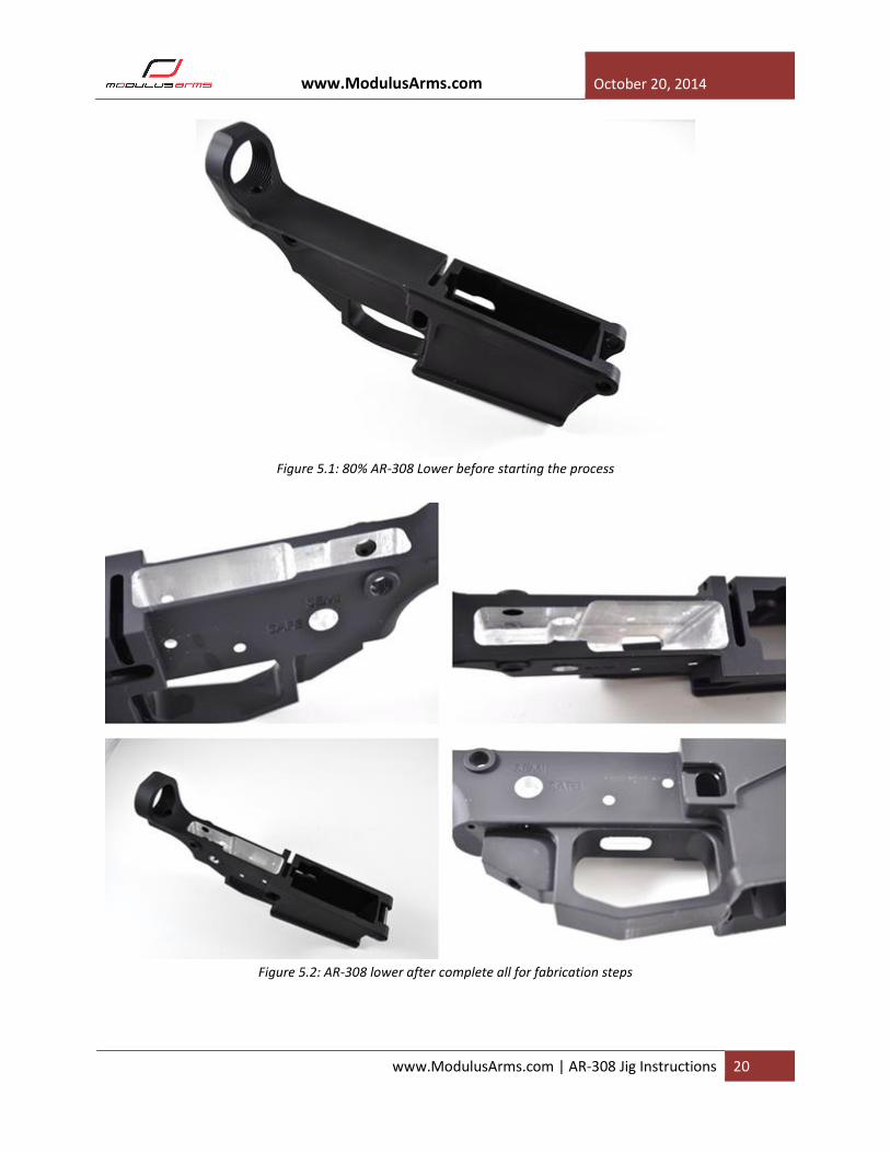
Figure 5.1 illustrates an 80% AR-308 lower as purchased. Figure 5.2 illustrates a completed lower using
the four steps outlined above. Figure 5.3 shows a complete lower after the lower parts kit and
buffer/stock assembly installed.
www.ModulusArms.com October 20, 2014
www.ModulusArms.com | AR-308 Jig Instructions 20
Figure 5.1: 80% AR-308 Lower before starting the process
Figure 5.2: AR-308 lower after complete all for fabrication steps

www.ModulusArms.com October 20, 2014
www.ModulusArms.com | AR-308 Jig Instructions 21
Figure 5.#: AR-308 completed lower after installation of the lower parts kit and buffer tube/stock assembly
Helpful Hints
This section will focus on additional hints and suggestions to improve the quality of the lower. The hints
and suggestions may be useful to both the first time novice as well as experienced 80% lower
fabricators.
Finishing Power Tools: The Modulus Arms jig is compatible with a number of different tools that can be
used to complete the drilling and milling process. Please make sure that you can safely operate the
power tools, and understand the manufacturer’s product manual.
A hand-drill or a drill press can be used to complete the 80% lower using the Modulus Arms jig. The
hand-drill is the lowest cost option, and its portability allows it to be easily borrowed from a friend or
rented. A drill press is a rarer and more expensive option, but results in reduced build time and
increased precision.
Drill Press
o Set the drill-press speed to approximately 2500 rpm.
o Make sure the drill bit is square to the table in both the x and y directions before using.
Hand-Drill
www.ModulusArms.com October 20, 2014
www.ModulusArms.com | AR-308 Jig Instructions 22
o Using the low (2-speed) or medium (3-speed) gear option if available.
o Best results are obtained with a more powerful, corded drill.
o Cordless drills will work; however, more than one battery and additional cool down times
may be required.
o For 7075 alloy lowers, the alloy is significantly more difficult to drill – a drill press is highly
recommended.
o Marking or center punching the drill spot on the lower can help increase accuracy. Using the
3/8” drill bit as a center punch, square the bit in the x and y direction with a right angle tool,
and lightly tap the end of the drill bit with a hammer to mark the center.
General Guidelines and Recommendations
o Make sure the drill bits are sharp – sharpen if necessary. Dull drill bits will result in
considerably higher effort and excessive temperatures.
o To prevent damage to the template edges, start the drill when the drill bit is through the
drill guide. After drilling, stop the drill bit before moving to the next hole.
o Frequently clear the chips by pulling the drill bit up but not out of the drill guide. The space
between the drill guide and lower is designed to accommodate the chips.
o Clear the chips between the drill guide and lower after each hole to prevent chips from
accumulating and compacting.
o Cutting oil or WD-40 applied with a toothbrush can reduce the drilling effort.
o After each hole, use the drill guide to check the depth to make sure the drill stop did not
slip.
For the milling process, the Modulus Arms jig is compatible with all common methods such as using a
drill press, router, or mini-mill. Using a drill press as a milling tool is NOT recommended and can be
dangerous. A router is common tool that is affordable and commonly used, making them easy to borrow
or rent. A mini-mill is a significantly more expensive option but results a significant reduction in build
time, and an increase in quality for the experienced user.
Drill-Press as a mill (NOT RECOMMENDED)
Router
o A router commonly used for woodworking with a standard ¼” collet.
o The end mill must be a 4” long, ¼” diameter end mill. Four flutes with less than a 1” cutting
depth is recommended for best results. Longer cutting surfaces can damage the jig. Always
check with the first cutting pass that the cutting flutes are below the jig template surface.
o Routers with variable speed give the bests results, although fixed speed routers can be used.
o Beware of inexpensive routers with a lot of flex – they can result in non-parallel walls and
damaged lowers.
o The results in these instructions were achieved with a Bosch PR20EVSK Colt Palm Grip
Router with the speed set at 4.
o End mill cut in a clockwise fashion. Best results are achieved with light clockwise semi-
circles, trying to keep only ¼ of the cutting surface on the metal to be removed.
www.ModulusArms.com October 20, 2014
www.ModulusArms.com | AR-308 Jig Instructions 23
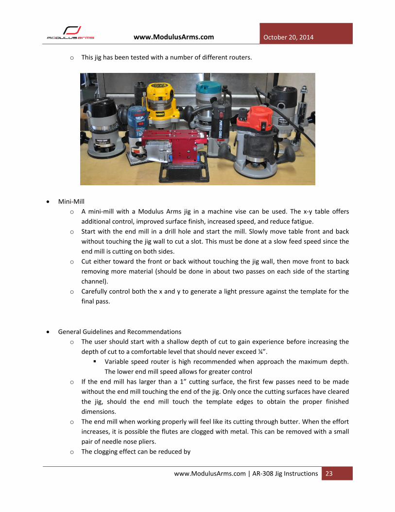
o This jig has been tested with a number of different routers.
Mini-Mill
o A mini-mill with a Modulus Arms jig in a machine vise can be used. The x-y table offers
additional control, improved surface finish, increased speed, and reduce fatigue.
o Start with the end mill in a drill hole and start the mill. Slowly move table front and back
without touching the jig wall to cut a slot. This must be done at a slow feed speed since the
end mill is cutting on both sides.
o Cut either toward the front or back without touching the jig wall, then move front to back
removing more material (should be done in about two passes on each side of the starting
channel).
o Carefully control both the x and y to generate a light pressure against the template for the
final pass.
General Guidelines and Recommendations
o The user should start with a shallow depth of cut to gain experience before increasing the
depth of cut to a comfortable level that should never exceed ¼”.
Variable speed router is high recommended when approach the maximum depth.
The lower end mill speed allows for greater control
o If the end mill has larger than a 1” cutting surface, the first few passes need to be made
without the end mill touching the end of the jig. Only once the cutting surfaces have cleared
the jig, should the end mill touch the template edges to obtain the proper finished
dimensions.
o The end mill when working properly will feel like its cutting through butter. When the effort
increases, it is possible the flutes are clogged with metal. This can be removed with a small
pair of needle nose pliers.
o The clogging effect can be reduced by

www.ModulusArms.com October 20, 2014
www.ModulusArms.com | AR-308 Jig Instructions 24
Frequently coating the end mill with cutting oil or WD-40 applied with a toothbrush.
If possible, reduce the speed of the end mill.
Misc. Tools: The following are suggestions based on our experience.
Vise: The vise and work surface must not move or flex when routing. The vise needs to be either
clamped or bolted to the work surface. A drill vise shown in the figure was selected due to its low-
cost, common availability, and low profile that reduces flexing.
Shop-Vac: Great at removing chips and cleaning up the work area to prevent spreading of metal
chips
Toothbrush: Can be used to apply a small amount of oil on the end mill.