AQVL/AQVH 85-140 - Systemair
40
AQVL/AQVH 85-140 Air Cooled Water Chillers Cooling Only and Heat Pump Engineering Data Manual Chiller 92 to 147 kW 83 to 137 kW
Transcript of AQVL/AQVH 85-140 - Systemair

AQVL/AQVH 85-140Air Cooled Water Chillers Cooling Only and Heat PumpEngineering Data Manual
Chiller
92 to 147 kW83 to 137 kW

| AQVL-AQVH2
High Performance Components
Specialinverter fan(option)
pCO1 control and PGD user interface
3 pump option Energy saving in partial load
EXVOptimization of superheating
True dual circuit evaporatorOptimized heat transfer coefficient
Compressor boxStandard on all units
360° accessible compressor box for maintenance
Blue fin coil as standard on HP models
800 mm, 6 poles, axial fans
100% 75% 50% 25%
High SEER

AQVL-AQVH | 3
Oustanding Strength Points Units with R410A refrigerant.
As near azeotropic mixture it behaves like a homogeneous substance (reduced service problems in case of leakage or re-charge) with negligible temperature glide.
Refrigerant with superior thermo-dynamical proprieties compared to R22 and R407C, it allows to have more efficiency or compact and lighter systems and larger operating limits (T ambient = -15 °C in heating mode).
2 independent refrigerant circuits with 2 scroll compressors for each circuit.
Bi-flow electronic expansion devices on all units : superheating value controlled by microprocessor, simple and accessible refrigeration system especially for heat pump versions with reduction of brazing points and then possible leakage.
V-shape condenser coils ensuring compactness and small foot print.
High EER and COP for fan coil application (water 12/7 °C cooling, 40/45 °C heating).
Excellent EER and COP for floor heating application (water 23/18 °C cooling, 30/35 °C heating).
High SEER.
2 acoustic versions : STD (Standard) and S (Super Low Noise).
Heat recovery option with desuperheater and total heat recovery.
Large choice of optional hydro kits with or without buffer tank fitted on board of the chiller to perform package solution and plug & play concept.
Electric heaters fitted inside buffer tank to ensure extra heating.
For safety purpose when performing service operation, special valves dedicated to R410A are supplied on the refrigerant system. These valves, of 5/16" flare SAE type, are mounted on the liquid line and on the gauges manifold of the unit.
GeneralThe new AQVL/AQVH units have been designed to operate with HFC 410A refrigerant. Both compressors and heat exchangers (plate heat exchanger and coils) have been optimized for this refrigerant.
All the units are available either in cooling only or heat pump version. Each unit consists of two independent refrigerant circuits and is complete with high efficient and advanced technology components :
- Hermetic Scroll compressors with high efficiency and low vibration emissions,
- Electronic expansion valves,
- "True dual" circuit plate heat exchanger,
- Quiet fans located in externally mounted nozzle profile housing generating low sound levels,
- Controller using a state-of-the-art microprocessor.
The AQVL/AQVH units are available in 6 sizes and 4 versions :
STD (Standard) version : Designed in accordance with specifications described in the following sections.
HSE (High Seasonal Efficiency) version : It has same equipment as that of the STD version, except that the units are equipped with special inverter fans, of large diameter, driven by EC (electronic brushless type) motors with integrated electronic inverter, to ensure low energy consumption.
HT (High Temperature) version : It has same equipment as HSE units, but the special inverter fans and motors have a different regulation.
HPF (High Pressure Fan) version : It has same equipment as STD units, except that the units are equipped with special inverter fans (same as those used on HSE version, but with a different regulation) driven by EC motors with integrated electronic inverter. The HPF version provides external static pressure up to 120 Pa.
The STD and HSE versions can be supplied with 2 acoustic options :
Standard (STD) : The units are equipped with star or delta connected fan motors depending on size. The chillers are not supplied with fan speed controller, but fitted with compressors box to reduce the noise emissions.
Super Low Noise (S) : The units are equipped with star connected fan motors, fitted with a speed controller which allows the units to operate with a very low rpm. The chillers are supplied with compressors box and soundproof jackets on compressors reducing significantly the noise emissions.
Specifications
On the other hand, the HT and HPF versions can be supplied with STD option only.
In addition, all the units can be supplied with 2 heat recovery options :
Desuperheater : All the versions can be supplied with plate type heat exchangers fitted, one on each refrigerant circuit, on the compressor discharge line to recover about 20 % of the total heat rejected to the condensers.
Total heat recovery (AQVR units) : All the versions of the cooling only units can be supplied with a double circuit plate type heat exchanger to recover 100 % of heat rejection by the condensers. 4-way valves and a field installed control sensor are also provided to ensure the cooling/heat recovery mode changeover.
Cabinet and structureThe cabinet and structure are made of heavy gauge galvanized steel. All galvanized steel components are individually painted by a special painting process before the assembly of the unit. This painting system performs a homogeneous protection to the corrosion.
The painting is a polyester powder based type, coloured in RAL 9001.
The units are suitable for outdoor installation, directly on the building roof or at the ground level.
Refrigerant circuitsAll the units are composed of two independent and separate refrigerant circuits, complete with 4 hermetic scroll compressors in tandem configuration for each circuit.
Each refrigerant circuit is equipped with liquid line and discharge line shut-off valves, filter-drier with solid core, sight glass and electronic expansion valve (EXV).
The heat pump units (AQVH) are provided with 4-way reversing valves, suction accumulators and liquid receivers on the liquid lines.
The AQVL and AQVH units are both provided with double-circuit plate heat exchangers, of "true dual" type.
The total heat recovery units are supplied with double-circuit water condenser (of plate heat exchanger type), 4-way reversing valves and liquid receivers downstream of the heat recovery condenser.
The functional diagram of each circuit is shown in the section "Refrigerant flow diagram".

| AQVL-AQVH4
CompressorsEach unit is equipped with 4 hermetic scroll compressors arranged in tandem configuration per refrigerant circuit.
The compressors are fitted with an electronic control device which ensures protection of compressors against :
- overheating and overloading,
- reversal rotation and phase loss.
All compressors have direct-on-line starting and are mounted on rubber vibration isolators in order to minimize noise and vibration transmission.
EvaporatorEvaporator is of a "Dual Circuit" brazed stainless steel plate type heat exchanger. It is insulated with a 19 mm thick closed cell polyethylene foam material and is fitted with a film type electric heater on the external surface to prevent the unit from freezing at a low temperature (down to -18 °C) when the unit is off.
Condenser coilsThe condenser coils are made of seamless copper tubes, arranged in staggered rows, mechanically expanded into corrugated aluminum fins.
They are mounted in V-shape arrangement, allowing the unit to be compact with small foot print.
The coils are supplied with blue fins on AQVH units to facilitate the flowing of water droplets during defrost cycles.
Condenser fansAll acoustic versions (STD & S) are equipped with large diameter, direct drive axial type fans with asynchronous three-phase motors.
Fans are fitted with externally mounted nozzle profile housing which generates low sound levels.
Fan speed controlThe airflow is controlled in order to operate at a low ambient temperature.
On standard unit equipped with axial fans, the air flow control is :
- step type for STD version without fan speed controls, achieved by switching off some fans of each circuit in function of condensing pressure corrected by external temperature.
- stepless type for S version, achieved by an electronic fan speed control, supplied as standard, in function of condensing pressure.
The pressure actuated stepless type fan speed controller can be supplied as optional on STD version. It allows the units to operate in cooling mode at ambient temperature down to -18 °C.
Electrical boardThe electrical board is located in a metal case arranged outside the unit and protected by a vertically pivoted access door. The metal case has an IP54 protection rating and is complete with grilles for natural air ventilation.
Electronic controlThe units are supplied with the new microprocessor-based electronic control and management system ensuring the following functions :
➜ Management of the operation of compressors :
a) Power on/off
b) Anticycle management
c) Tandem unloading for high pressure or high compressor pressure ratio (integrated inside the curves of compressor operating limits).
➜ Chilled and hot water temperature regulation (control option on inlet water temperature RWT (PID) or outlet water temperature LWT (neutral band type) of the evaporator.
➜ Control of superheating on suction line.
➜ Evaporator antifreeze protection.
➜ Heat pump defrost control for automatic operation.
➜ Management of high and low pressure alarms.
➜ Management of the electronic expansion valves by means of EXV controller allowing optimized functions : cooling, heating, start-up and defrost.
➜ Management of external interlocks.
➜ Management of the remote control :
d) Unit power on/off
e) Summary alarm signals
➜ Remote signalling, by dry contacts :
f) Voltage presence
g) Compressors in operation
h) Circuit alarm unit
➜ Management of the hydro kit : start-up of pump, antifreeze heater of external tank.
➜ Management of the heat recovery mode by means of inlet water temperature sensor at the heat recovery condenser.
The unit controller can also clearly show all control parameters of the machine on the liquid crystal display, such as :
➜ Display of superheating value.
➜ Display of the temperature at the evaporator inlet and outlet.
➜ Display of the ambient air temperature.
➜ Display of the circuit 1 and circuit 2 discharge pressure and suction pressure.
➜ Display of the set point.
➜ Display of opening steps of EEV.
➜ Display of speed control signal (voltage) of fans.
➜ Display of the various alarm and operation status :
i) Compressor start-up alarm (discharge pressure check)
j) Low / High pressure
k) Low / High super-heating
l) Evaporator antifreeze
m) Flow switch signal for lack of water
n) Control of the compressor operating hours
o) Compressors in operation
p) Pump in operation and operating hours
q) Thermal protection of compressors
r) Thermal protection of fans
s) Faulty sensors
Control and safety devicesEach unit is fitted with the following devices :
Safety :➜ Power disconnect switch with an emergency stop function.
➜ HP switches (double on each circuit), set to 40.5 bar, automatic reset and manual reset from the control panel.
➜ Flow switch on the evaporator side.
➜ Antifreeze temperature sensor (set to +4 °C) on the evaporator (AQVL/AQVH only).
➜ Safety valve on the discharge line and the liquid receiver (on AQVH), set to 45 bar.
Specifications (continued)

AQVL-AQVH | 5
Control :➜ HP and LP transducers (two for each circuit).
➜ Evaporator water inlet temperature sensor.
➜ Evaporator water outlet temperature sensor (with an antifreeze function).
➜ Suction temperature sensor for EXV control.
➜ Ambient air temperature sensor.
➜ Coil temperature sensors.
➜ Heat recovery condenser temperature sensor (AQVR only).
Conformity with standardsThe following applies to all the sizes and versions of AQVL/AQVH/AQVR units :
3 Machine Directive : 2006/42/EC
3 Low Voltage Directive : 2006/95/EC
3 Electromagnetic Compatibility Directive : 2004/108/EC
3 Pressure Equipment Directive : 97/23/EC
Standard equipment3 Back light display.
3 Digital pressure and temperature reading kit.
3 High ambient pressure control.
3 Double set point (AQVL/AQVH only).
3 Sequence phase control.
3 Electronic expansion valves.
3 Control circuit transformer 400 V/230 V.
3 Data logger.
3 Power supply single point box.
3 Power supply without neutral.
3 Hour meter.
3 Main switch.
3 Refrigerant R410A.
3 PED approval.
3 Blue fin coils (AQVH only).
3 Evaporator antifreeze electric heater.
3 Compressor jacket (S version only).
3 Compressor box.
3 Rubber anti-vibration pads.
Optional hydro kitsAll hydro kits are supplied fitted inside the unit with or without buffer tank. They are available for AQVL and AQVH units only.
- 1P : 1 low or high pressure pump kit with relevant accessories.
- 2P : 2 low or high pressure pump kit with relevant accessories.
- 3P : 3 low or high pressure pump kit with relevant accessories.
- 1P+T : 1P kit + buffer tank covered with insulation and fitted with an antifreeze electric heater.
- 2P+T : 2P kit + buffer tank covered with insulation and fitted with an antifreeze electric heater.
When thermodynamic heating is not sufficient, optional electric heaters can be provided inside buffer tank to ensure extra heating.
Factory-installed options
3 ModBus protocol kit for BMS.
3 Lonwork protocol kit for BMS.
3 Bacnet protocol kit for BMS.
3 WEBctrl.
3 Ethernet TCP/IP interface board.
3 Compressor soft starter.
3 Pressure actuated stepless fan speed controller for low ambient operation
(-18 °C) (STD version).
3 Power factor correction capacitors.
3 Compressor overload protection.
3 Automatic circuit breaker.
3 GSM.
3 HP & LP manometers.
3 Condenser coils with "Fin Guard Silver" (polyurethane) treatment.
3 Condenser coils with copper fins.
3 Condenser coils with black epoxy treatment.
3 Coil guards.
3 Chiller grilles.
3 Compressor jacket.
3 Total heat recovery (AQVR).
3 Desuperheater.
3 On board hydro kits.
3 Electric heaters inside buffer tank, used as extra heating.
3 Automatic pump switch on 2 pump kit.
3 Antifreeze electric heater for hydraulic manifolds.
Field-installed accessories
3 Remote keyboard panel.
3 Master and slaves control, up to 4 units max.
3 Chiller grilles.
3 Pressure switch.
3 Water filter.
Specifications (continued)

| AQVL-AQVH6
Hydro Options1P
3P
2P + T
2P
1P + T
All hydro options are supplied fitted inside the unit.

AQVL-AQVH | 7
Refrigerant Flow Diagram - AQVL Units
SAFETY/CONTROL DEVICESA High pressure switch
AT High pressure transducer
B Low pressure switch (1.5 bar)
BT Low pressure transducer
FS Water flow switch
D Air temperature sensor
E Outlet water temperature sensor
F Inlet water temperature sensor
G PED pressure relief valve
M Discharge temperature sensor
S 5/16" shrader connection (service only)
Pipe connection with shrader valve
COMPONENTS1 Compressor tandem scroll type
2 Air cooled condenser
3 Filter drier
4 Electronic expansion valve
5 Globe valve
6 Plate heat exchanger (Dual type)
7 Desuperheater (optional)
Note: For reasons of readability, one circuit only is shown. The second circuit is identical.
5
1
OIL EQUAL.
D
2
3
5
6BT
EF
G
7
EXVCONTROL
UNITCONTROL
S
ATA
S
FS
4
S
M
B
S

| AQVL-AQVH8
Refrigerant Flow Diagram - AQVH Units
SAFETY/CONTROL DEVICESA High pressure switch
AT High pressure transducer
B Low pressure switch (1.5 bar)
BT Low pressure transducer
FS Water flow switch
D Air temperature sensor
E Outlet water temperature sensor
F Inlet water temperature sensor
G PED pressure relief valve
H Defrost temperature sensor
M Discharge temperature sensor
N Suction temperature sensor
S 5/16" shrader connection (service only)
Pipe connection with shrader valve
COMPONENTS1 Compressor tandem scroll type
2 Air cooled condenser
3 Filter drier
4 Electronic expansion valve
5 Globe valve
7 Liquid receiver
8 Four-way valve
9 Suction accumulator
10 Sight glass
11 Plate heat exchanger (Dual type)
12 Desuperheater (optional)
Note: For reasons of readability, one circuit only is shown. The second circuit is identical.
11
F F
8
ON
OIL EQUAL.
1
S A M AT
12
EXVCONTROL
UNITCONTROL
7
G
13
4
13
3
S
10
S
13 13
5
5G
2
D
HS BT9
B N

AQVL-AQVH | 9
Hydraulic Circuit Diagram
1
B
A
10
5
G
G
9
11
1112
12
13
INLET
OUTLET
FS
8
8
COMPONENTS1 Plate heat exchanger5 Water filter8 Pressure point/drain valve9 Water outlet
10 Water inlet11 Globe valve12 Flexible pipes13 By-pass valve
SAFETY/CONTROL DEVICESA Inlet water temperature sensorB Outlet water temperature sensorFS Flow switchG Thermometer
Unit side
8
26
E
8 8
FS
OUTLET
INLET
13
12
12 11
11
9
G
G
5
10
A
B
1
7D
Basic unit
1P unit
COMPONENTS1 Plate heat exchanger2 Pump5 Water filter7 Pressure expansion tank8 Pressure point/drain valve9 Water outlet
10 Water inlet11 Globe valve12 Flexible pipes13 By-pass valve
SAFETY/CONTROL DEVICESA Inlet water temperature sensorB Outlet water temperature sensorD Vent valveE Water safety valve (6 bar)FS Flow switchG Thermometer
Unit side

| AQVL-AQVH10
Hydraulic Circuit Diagram (continued)2P unit
3P unit
D
71
B
A
10
5
G
G
9
11
1112
12
13
INLET
OUTLET
FS
8 8
E
8
2
2
6
6
D
7
1
B
A
10
5
G
G
9
11
1112
12
13
INLET
OUTLET
FS
8 8
E
8
2
2
6
26
6
COMPONENTS1 Plate heat exchanger2 Pump5 Water filter6 Non-return valve7 Pressure expansion tank8 Pressure point/drain valve9 Water outlet
10 Water inlet11 Globe valve12 Flexible pipes13 By-pass valve
COMPONENTS1 Plate heat exchanger2 Pump5 Water filter6 Non-return valve7 Pressure expansion tank8 Pressure point/drain valve9 Water outlet
10 Water inlet11 Globe valve12 Flexible pipes13 By-pass valve
SAFETY/CONTROL DEVICESA Inlet water temperature sensorB Outlet water temperature sensorD Vent valveE Water safety valve (6 bar)FS Flow switchG Thermometer
Unit side
SAFETY/CONTROL DEVICESA Inlet water temperature sensorB Outlet water temperature sensorD Vent valveE Water safety valve (6 bar)FS Flow switchG Thermometer
Unit side

AQVL-AQVH | 11
Hydraulic Circuit Diagram (continued)1P+T unit
2P+T unit
8
3
Y
26
E8 8
FS
OUTLET
INLET
13
12
12 11
11
9
G
G
5
10
A
B
1
7
4
11
D
D
8
3
Y
26E8 8
FS
OUTLET
INLET
13
12
12 11
11
9
G
G
5
10
A
B
1
7
4
11
D
D
26
COMPONENTS1 Plate heat exchanger2 Pump3 Draining valve4 Water buffer tank5 Water filter7 Pressure expansion tank8 Pressure point/drain valve9 Water outlet
10 Water inlet11 Globe valve12 Flexible pipes13 By-pass valve
COMPONENTS1 Plate heat exchanger2 Pump3 Draining valve4 Water buffer tank5 Water filter7 Pressure expansion tank8 Pressure point/drain valve9 Water outlet
10 Water inlet11 Globe valve12 Flexible pipes13 By-pass valve
SAFETY/CONTROL DEVICESA Inlet water temperature sensorB Outlet water temperature sensorD Vent valveE Water safety valve (6 bar)FS Flow switchG Thermometer
Unit sideY Drainage water
SAFETY/CONTROL DEVICESA Inlet water temperature sensorB Outlet water temperature sensorD Vent valveE Water safety valve (6 bar)FS Flow switchG Thermometer
Unit sideY Drainage water

| AQVL-AQVH12
Notes : Operating limits are referred to full load (4 compressors running).Maximum %glycol (ethylenic or propilenic) : 40%
Notes : Operating limits are referred to full load (4 compressors running).Maximum %glycol (ethylenic or propilenic) : 40%
Operating LimitsAQVL/AQVH 85 to 140 - R410A - STD/S Version - Cooling
AQVL/AQVH 85 to 140 - R410A - HSE/HT Version - Cooling
-20
-15
-10
-5
0
5
10
15
20
25
30
35
40
45
50
-9 -8 -7 -6 -5 -4 -3 -2 -1 0 1 2 3 4 5 6 7 8 9 10 11 12 13 14 15 16 17 18 19
-20
-15
-10
-5
0
5
10
15
20
25
30
35
40
45
50
55
-9 -8 -7 -6 -5 -4 -3 -2 -1 0 1 2 3 4 5 6 7 8 9 10 11 12 13 14 15 16 17 18 19
Water + Glycol
Water + Glycol
Leaving water temperature (°C)
STD
85-115
S
125-140
Leaving water temperature (°C)
Outd
oor a
ir te
mpe
ratu
re (°
C)Ou
tdoo
r air
tem
pera
ture
(°C)
Water + Glycol + Fan speed controller
Water
Water
Water + Fan speed controller
AQVL-AQVH | 13
STD
85-115
S
125-140
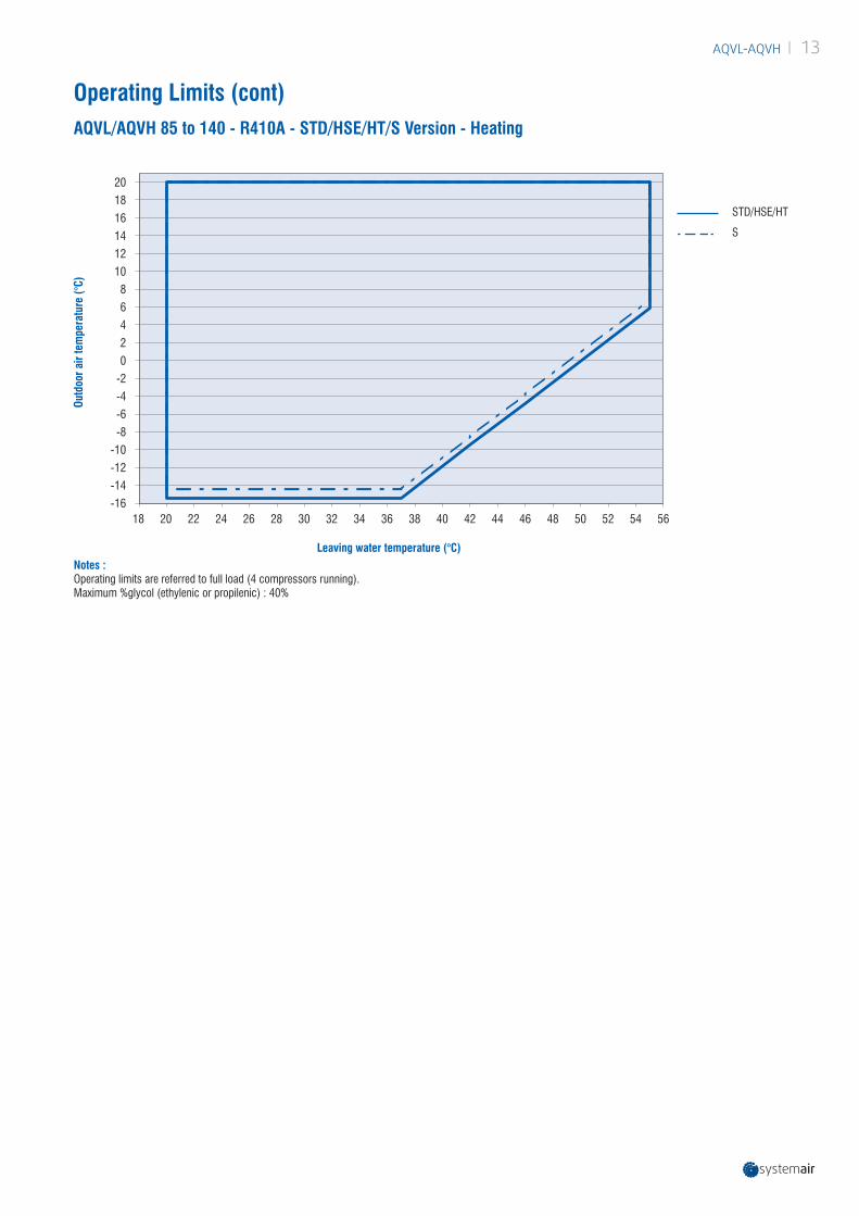
Operating Limits (cont)AQVL/AQVH 85 to 140 - R410A - STD/HSE/HT/S Version - Heating
18 20 22 24 26 28 30 32 34 36 38 40 42 44 46 48 50 52 54 56-16
-14
-12
-10
-8
-6
-4
-2
0
2
4
6
8
10
12
14
16
18
20
Notes : Operating limits are referred to full load (4 compressors running).Maximum %glycol (ethylenic or propilenic) : 40%
Leaving water temperature (°C)
Outd
oor a
ir te
mpe
ratu
re (°
C)
STD/HSE/HT
S

| AQVL-AQVH14
Correction Factors
Fouling factor (m2.°C/kW) Cooling capacity factor Power input factor
0.044 1.000 1.000
0.088 0.987 0.995
0.176 0.964 0.985
0.352 0.915 0.962
Models Water temperature in/out Cooling capacity (kW) Power input (kW)
AQVL - AQVH
17/7(10) 95% 98%
14/7(7) 97% 99%
12/7(5) 100% 100%
10/7 (3) 103% 101%
Altitude (m) Cooling capacity factor Power input factor
0 1.000 1.000
600 0.987 1.010
1200 0.973 1.020
1800 0.958 1.030
2400 0.943 1.040
Fouling factor (m2.°C/kW) Cooling capacity factor Power input factor
0.044 1.000 1.000
0.088 0.987 1.023
0.176 0.955 1.068
0.352 0.910 1.135
Fouling factors - Evaporator
Fouling factors - Condenser
Correction factors for water ∆T different from 5 K
Altitude factors

AQVL-AQVH | 15
Technical Data - AQVL 85 to 140 - R410A - STD/HSE/HPF - STD VersionAQVL Sizes - STD/HSE/HPF - STD Version 85 95 105 115 125 140Cooling Capacity (1) kW 83,3 93,3 102,4 110,1 121,9 136,6Input Power (Compressor) (1) kW 27,1 31 33,6 36,5 41,1 45,9Total EER / Energy efficiency class (1) 3,08/B 3,01/B 3,05/B 3,02/B 2,97/B 2,97/BSEER / hsc (2) 4,55/ 179 4,8/ 189 4,78/ 188 4,8/ 189 4,73/ 186 4,53/ 178Total EER / Energy eff. class (HSE/HPF) (1) 3,19/A 3,1/A 3,13/A 3,09/B 3,05/B 3,04/BSEER (HSE/ HPF) / hsc (HSE/ HPF) (2) 4,73/186 4,75/187 4,95/195 4,95/195 4,78/188 4,6/181Number of Refrigerant Circuits 2 2 2 2 2 2Part Load Steps % 0-25-50-75-100 0-25-50-75-100 0-24-47-74-100 0-25-50-75-100 0-22-43-72-100 0-25-50-75-100Power Supply 400V/3/50Hz 400V/3/50Hz 400V/3/50Hz 400V/3/50Hz 400V/3/50Hz 400V/3/50HzStartup Type Direct Direct Direct Direct Direct DirectREFRIGERANTType R410ACharge kg 17,6 19,7 21,6 23,2 25,7 28,8COMPRESSORNumber 4 4 4 4 4 4Type Scroll Scroll Scroll Scroll Scroll ScrollCrankcase Heater W 90 90 90 90 90 90EVAPORATORNumber 1 1 1 1 1 1Type Plate Plate Plate Plate Plate PlateWater flow Rate l/h 14377 16116 17681 19023 21033 23588Water Pressure Drop kPa Refer to evaporator water pressure drop curveAntifreeze Heater W 130 130 130 130 130 130DESUPERHEATERNumber 2 2 2 2 2 2Type Plate Plate Plate Plate Plate PlateHeat recovery kW 21,6 24,4 26,8 28,9 31,9 35,9Water flow rate l/h 3721 4202 4604 4970 5486 6167Water Pressure Drop kPa Refer to desuperheater water pressure dropCOILNumber 2 2 2 2 2 2Frontal Surface l x a 2000 x 1200 2000 x 1200 2000 x 1200 2000 x 1200 2600 x 1200 2600 x 1200FANSNumber 2 2 2 2 2 2Air Flow Rate m³/h 34000 34000 33200 32400 44000 42800Speed rpm 690 690 690 690 900 900Input Power kW 2,1 2,1 2,1 2,1 3,4 3,4Input Power HSE kW 1,2 1,2 1,2 1,2 2,4 2,4Input Power HPF kW 3,6 3,6 3,6 3,6 4,6 4,6WATER CONNECTIONS (EVAPORATOR)Type Male GAS ThreadedInlet Diameter inch 2"1/2 2"1/2 2"1/2 2"1/2 2"1/2 2"1/2Outlet Diameter inch 2"1/2 2"1/2 2"1/2 2"1/2 2"1/2 2"1/2WATER CONNECTIONS (DESUPERHEATER)Type Male GAS ThreadedInlet Diameter inch 1" 1" 1" 1" 1" 1"Outlet Diameter inch 1" 1" 1" 1" 1" 1"WEIGHTShipping Weight kg 1033 1047 1084 1116 1151 1230Operating Weight kg 1058 1072 1111 1143 1183 1262DIMENSIONSLength mm 2555 2555 2555 2555 3155 3155Width (transport only) mm 1095 (1250) 1095 (1250) 1095 (1250) 1095 (1250) 1095 (1250) 1095 (1250)Height mm 2185 2185 2185 2185 2185 2185ACOUSTIC DATASound Power Level (3) dB(A) 85 85 85 85 89 89Sound Pressure Level (4) dB(A) 53 53 53 53 57 57Sound Power Level HPF (3) dB(A) 92 92 92 92 95 95Sound Pressure Level HPF (4) dB(A) 60 60 60 60 63 63
(1) According EN14511: chilled water inlet/outlet temperature: 12/7°C, outdoor ambient temperature 35°C DB.(2) According EN14825 and following COMMISSION REGULATION (EU) No 2016/2281 for comfort application chillers <400kW.(3) Sound levels are at fully loaded conditions. Sound power level values refers to ISO 3744 standard.(4) Sound pressure calculated at 10 m. Sound pressure levels refer to ISO standard 3744 with parallepiped shape.

| AQVL-AQVH16
Technical Data - AQVL 85 to 140 - R410A - STD/HSE - S VersionAQVL Sizes - STD/HSE - S Version 85 95 105 115 125 140Cooling Capacity (1) kW 80,6 89,9 98,3 105,4 119,1 133,1Input Power (Compressor) (1) kW 28 32,6 35,5 38,6 41,1 46,5Total EER / Energy efficiency class (1) 2,87/C 2,76/C 2,77/C 2,73/C 2,9/B 2,86/CSEER / hsc (2) 4,75/ 187 4,78/ 188 4,98/ 196 5,0/ 197 4,8/ 189 4,6/ 181Total EER / Energy eff. class(HSE) (1) 3,00/B 2,87/C 2,87/C 2,81/C 2,96/B 2,91/BSEER (HSE) / hsc (HSE) (2) 4,8/ 189 4,75/ 187 4,88/ 192 4,88/192 4,9/193 4,7/185Number of Refrigerant Circuits 2 2 2 2 2 2Part Load Steps % 0-25-50-75-100 0-25-50-75-100 0-24-47-74-100 0-25-50-75-100 0-22-43-72-100 0-25-50-75-100Power Supply 400V/3/50Hz 400V/3/50Hz 400V/3/50Hz 400V/3/50Hz 400V/3/50Hz 400V/3/50HzStartup Type Direct Direct Direct Direct Direct DirectREFRIGERANTType R410ACharge kg 17,0 19,0 20,7 22,2 25,1 28,1COMPRESSORNumber 4 4 4 4 4 4Type Scroll Scroll Scroll Scroll Scroll ScrollCrankcase Heater W 90 90 90 90 90 90EVAPORATORNumber 1 1 1 1 1 1Type Plate Plate Plate Plate Plate PlateWater flow Rate l/h 13906 15532 16971 18204 20550 22988Water Pressure Drop kPa Refer to evaporator water pressure drop curveAntifreeze Heater W 130 130 130 130 130 130DESUPERHEATERNumber 2 2 2 2 2 2Type Plate Plate Plate Plate Plate PlateHeat recovery kW 21,4 24,1 26,4 28,5 31,6 35,5Water flow rate l/h 3677 4152 4540 4894 5438 6108Water Pressure Drop kPa Refer to desuperheater water pressure dropCOILNumber 2 2 2 2 2 2Frontal Surface l x a 2000 x 1200 2000 x 1200 2000 x 1200 2000 x 1200 2600 x 1200 2600 x 1200FANSNumber 2 2 2 2 2 2Air Flow Rate m³/h 25200 25200 24600 24000 36500 35000Speed rpm 500 500 500 500 690 690Input Power kW 1,8 1,8 1,8 1,8 2,1 2,1Input Power HSE kW 0,6 0,6 0,6 0,6 1,2 1,2WATER CONNECTIONS (EVAPORATOR)Type Male GAS ThreadedInlet Diameter inch 2"1/2 2"1/2 2"1/2 2"1/2 2"1/2 2"1/2Outlet Diameter inch 2"1/2 2"1/2 2"1/2 2"1/2 2"1/2 2"1/2WATER CONNECTIONS (DESUPERHEATER)Type Male GAS ThreadedInlet Diameter inch 1" 1" 1" 1" 1" 1"Outlet Diameter inch 1" 1" 1" 1" 1" 1"WEIGHTShipping Weight kg 1063 1077 1114 1146 1181 1260Operating Weight kg 1088 1102 1141 1173 1213 1292DIMENSIONSLength mm 2555 2555 2555 2555 3155 3155Width (transport only) mm 1095 (1250) 1095 (1250) 1095 (1250) 1095 (1250) 1095 (1250) 1095 (1250)Height mm 2185 2185 2185 2185 2185 2185ACOUSTIC DATASound Power Level (3) dB(A) 82 82 82 82 86 86Sound Pressure Level (4) dB(A) 50 50 50 50 54 54
(1) According EN14511: chilled water inlet/outlet temperature: 12/7°C, outdoor ambient temperature 35°C DB.(2) According EN14825 and Following COMMISSION REGULATION (EU) No 2016/2281 for comfort application chillers <400kW.(3) Sound levels are at fully loaded conditions. Sound power level values refers to ISO 3744 standard.(4) Sound pressure calculated at 10 m. Sound pressure levels refer to ISO standard 3744 with parallepiped shape.

AQVL-AQVH | 17
Technical Data - AQVL 85 to 140 - R410A - HTAQVL Sizes - HT 85 95 105 115 125 140
Cooling Capacity (1) kW 86,2 96,9 107 115 124 139
Input Power (Compressor) (1) kW 28,1 31,6 33,9 36,4 41,1 46
Total EER (1) 3,19 3,1 3,13 3,09 3,05 3,04
SEER / hsc (2) 4,73/186 4,75/187 4,95/195 4,95/195 4,78/188 4,6/181
Number of Refrigerant Circuits 2 2 2 2 2 2
Part Load Steps % 0-25-50-75-100 0-25-50-75-100 0-24-47-74-100 0-25-50-75-100 0-22-43-72-100 0-25-50-75-100
Power Supply 400V/3/50Hz 400V/3/50Hz 400V/3/50Hz 400V/3/50Hz 400V/3/50Hz 400V/3/50Hz
Startup Type Direct Direct Direct Direct Direct Direct
REFRIGERANT
Type R410A
Charge kg 18 20 22 24 26 29
COMPRESSOR
Number 4 4 4 4 4 4
Type Scroll Scroll Scroll Scroll Scroll Scroll
Crankcase Heater W 90 90 90 90 90 90
EVAPORATOR
Number 1 1 1 1 1 1
Type Plate Plate Plate Plate Plate Plate
Water flow Rate l/h 14835 16680 18381 19838 21427 24014
Water Pressure Drop kPa Refer to evaporator water pressure drop curve
Antifreeze Heater W 130 130 130 130 130 130
DESUPERHEATER
Number 2 2 2 2 2 2
Type Plate Plate Plate Plate Plate Plate
Heat recovery kW 21,9 24,7 27,2 29,3 32,1 36,1
Water flow rate l/h 3766 4253 4671 5047 5526 6209
Water pressure drop kPa Refer to desuperheater water pressure drop curve
COIL
Number 2 2 2 2 2 2
Frontal Surface l x a 2000 x 1200 2000 x 1200 2000 x 1200 2000 x 1200 2600 x 1200 2600 x 1200
FANS
Number 2 2 2 2 2 2
Air Flow Rate m³/h 49700 49700 48950 48200 52200 50700
Speed rpm 1130 1130 1130 1130 1130 1130
Input Power kW 4,6 4,6 4,6 4,6 4,6 4,6
WATER CONNECTIONS (EVAPORATOR)
Type Male GAS Threaded
Inlet Diameter inch 2"1/2 2"1/2 2"1/2 2"1/2 2"1/2 2"1/2
Outlet Diameter inch 2"1/2 2"1/2 2"1/2 2"1/2 2"1/2 2"1/2
WATER CONNECTIONS (DESUPERHEATER)
Type Male GAS Threaded
Inlet Diameter inch 1" 1" 1" 1" 1" 1"
Outlet Diameter inch 1" 1" 1" 1" 1" 1"
WEIGHT
Shipping Weight kg 1033 1047 1084 1116 1151 1230
Operating Weight kg 1058 1072 1111 1143 1183 1262
DIMENSIONS
Length mm 2555 2555 2555 2555 3155 3155
Width (transport only) mm 1095 (1250) 1095 (1250) 1095 (1250) 1095 (1250) 1095 (1250) 1095 (1250)
Height mm 2185 2185 2185 2185 2185 2185
ACOUSTIC DATA
Sound Power Level (3) dB(A) 95 95 95 95 95 95
Sound Pressure Level (4) dB(A) 63 63 63 63 63 63(1) According EN14511: chilled water inlet/outlet temperature: 12/7°C, outdoor ambient temperature 35°C DB.(2) According EN14825 and following COMMISSION REGULATION (EU) No 2016/2281 for comfort application chillers <400kW.(3) Sound levels are at fully loaded conditions. Sound power level values refers to ISO 3744 standard.(4) Sound pressure calculated at 10 m. Sound pressure levels refer to ISO standard 3744 with parallepiped shape.

| AQVL-AQVH18
Technical Data - AQVH 85 to 140 - R410A - STD/HSE/HPF - STD VersionAQVH Sizes - STD/HSE/HPF - STD Version 85 95 105 115 125 140Cooling Capacity (1) kW 81 89,9 98,9 106,9 115,8 129,2Input Power (Compressor) (1) kW 27,5 31,5 34,2 36,9 41,8 46,5Total EER / Energy efficiency class (1) 2,95/B 2,85/C 2,89/B 2,89/C 2,77/C 2,78/CSEER / hsc (2) 4,25/167 4,68/184 4,63/182 4,17/164 4,33/170 4,28/168Total EER / Energy eff. class (HSE/HPF) (1) 3,05/B 2,94/B 2,97/B 2,96/B 2,84/C 2,84/CSEER (HSE/ HPF) / hsc (HSE/ HPF) (2) 4,6/181 5,03/198 4,95/195 4,55/179 4,6/181 4,5/177Heating Capacity (3) kW 91,8 102,8 110 119 134 146,9Input Power (Compressor) (3) kW 26,84 30,5 32,2 35,2 40,9 44,8Total COP (3) 3,42 3,37 3,42 3,38 3,28 3,28Total COP (HSE/HPF) (3) 3,54 3,47 3,52 3,47 3,36 3,36SCOP / hsh (4) 3,61/141 3,64/143 3,78/148 3,77/148 3,47/136 3,54/139Number of Refrigerant Circuits 2 2 2 2 2 2Part Load Steps % 0-25-50-75-100 0-25-50-75-100 0-24-47-74-100 0-25-50-75-100 0-22-43-72-100 0-25-50-75-100Power Supply 400V/3/50Hz 400V/3/50Hz 400V/3/50Hz 400V/3/50Hz 400V/3/50Hz 400V/3/50HzStartup Type Direct Direct Direct Direct Direct DirectREFRIGERANTType R410ACharge kg 21,1 23,4 25,8 27,9 30,2 33,7COMPRESSORNumber 4 4 4 4 4 4Type Scroll Scroll Scroll Scroll Scroll ScrollCrankcase Heater W 90 90 90 90 90 90EVAPORATORNumber 1 1 1 1 1 1Type Plate Plate Plate Plate Plate PlateWater flow Rate l/h 13967 15508 17060 18431 19987 22288Water Pressure Drop kPa Refer to evaporator water pressure drop curveAntifreeze Heater W 130 130 130 130 130 130DESUPERHEATERNumber 2 2 2 2 2 2Type Plate Plate Plate Plate Plate PlateHeat recovery kW 21,3 23,9 26,2 28,3 30,8 34,4Water flow rate l/h 3657 4103 4505 4873 5306 5922Water Pressure Drop kPa Refer to desuperheater water pressure dropCOILNumber 2 2 2 2 2 2Frontal Surface l x a 2000 x 1200 2000 x 1200 2000 x 1200 2000 x 1200 2600 x 1200 2600 x 1200FANSNumber 2 2 2 2 2 2Air Flow Rate m³/h 34700 34700 34050 33400 44500 43200Speed rpm 690 690 690 690 900 900Input Power kW 2,1 2,1 2,1 2,1 3,4 3,4Input Power HSE kW 1,2 1,2 1,2 1,2 2,4 2,4Input Power HPF kW 3,6 3,6 3,6 3,6 4,6 4,6WATER CONNECTIONS (EVAPORATOR)Type Male GAS ThreadedInlet Diameter inch 2"1/2 2"1/2 2"1/2 2"1/2 2"1/2 2"1/2Outlet Diameter inch 2"1/2 2"1/2 2"1/2 2"1/2 2"1/2 2"1/2WATER CONNECTIONS (DESUPERHEATER)Type Male GAS ThreadedInlet Diameter inch 1" 1" 1" 1" 1" 1"Outlet Diameter inch 1" 1" 1" 1" 1" 1"WEIGHTShipping Weight kg 1065 1080 1122 1153 1196 1270Operating Weight kg 1090 1105 1149 1180 1227 1301DIMENSIONSLength mm 2555 2555 2555 2555 3155 3155Width (transport only) mm 1095 (1250) 1095 (1250) 1095 (1250) 1095 (1250) 1095 (1250) 1095 (1250)Height mm 2185 2185 2185 2185 2185 2185ACOUSTIC DATASound Power Level (5) dB(A) 85 85 85 85 89 89Sound Pressure Level (6) dB(A) 53 53 53 53 57 57Sound Power Level HPF (5) dB(A) 92 92 92 92 95 95Sound Pressure Level HPF (6) dB(A) 60 60 60 60 63 63
(1) According EN14511: chilled water inlet/outlet temperature: 12/7°C, outdoor ambient temperature 35°C DB.(2) According EN14825 and following COMMISSION REGULATION (EU) No 2016/2281 for comfort application chillers <400kW.(3) According EN14511: warm water inlet/outlet temperature: 40/45°C, outdoor ambient temperature 7°C DB/6°C WB.(4) According EN14825 and following COMMISSION REGULATION (EU) No 813/2013 for low-temperature heat pumps.(5) Sound levels are at fully loaded conditions. Sound power level values refers to ISO 3744 standard.(6) Sound pressure calculated at 10 m. Sound pressure levels refer to ISO standard 3744 with parallepiped shape.

AQVL-AQVH | 19
Technical Data - AQVH 85 to 140 - R410A - STD/HSE - S VersionAQVH Sizes - STD/HSE - S Version 85 95 105 115 125 140Cooling Capacity (1) kW 78,4 86,7 95,1 102 112 124,6Input Power (Compressor) (1) kW 28,6 33,2 36 39,1 43,1 47,6Total EER / Energy efficiency class (1) 2,75/C 2,61/D 2,64/D 2,62/D 2,61/D 2,63/DSEER / hsc (2) 4,25/167 4,68/184 4,63/182 4,17/164 4,33/170 4,28/168Total EER / Energy eff. class (HSE) (1) 2,84/C 2,69/D 2,71/C 2,69/D 2,65/D 2,67/DSEER (HSE) / hsc (HSE) (2) 4,6/181 5,03/198 4,95/195 4,55/179 4,6/181 4,5/177Heating Capacity (3) kW 89,5 99,8 108 115 129 142Input Power (Compressor) (3) kW 26,4 30,1 32 34,7 39,3 43Total COP (3) 3,39 3,32 3,36 3,32 3,29 3,3Total COP (HSE) (3) 3,55 3,46 3,5 3,45 3,38 3,38SCOP / hsh (4) 3,61/141 3,64/143 3,78/148 3,77/148 3,47/136 3,54/139Number of Refrigerant Circuits 2 2 2 2 2 2Part Load Steps % 0-25-50-75-100 0-25-50-75-100 0-24-47-74-100 0-25-50-75-100 0-22-43-72-100 0-25-50-75-100Power Supply 400V/3/50Hz 400V/3/50Hz 400V/3/50Hz 400V/3/50Hz 400V/3/50Hz 400V/3/50HzStartup Type Direct Direct Direct Direct Direct DirectREFRIGERANTType R410ACharge kg 20,4 22,6 24,7 26,7 29,2 32,5COMPRESSORNumber 4 4 4 4 4 4Type Scroll Scroll Scroll Scroll Scroll ScrollCrankcase Heater W 90 90 90 90 90 90EVAPORATORNumber 1 1 1 1 1 1Type Plate Plate Plate Plate Plate PlateWater flow Rate l/h 13496 14924 16355 17632 19349 21508Water Pressure Drop kPa Refer to evaporator water pressure drop curveAntifreeze Heater W 130 130 130 130 130 130DESUPERHEATERNumber 2 2 2 2 2 2Type Plate Plate Plate Plate Plate PlateHeat recovery kW 21,0 23,6 25,8 27,9 30,7 34,0Water flow rate l/h 3614 4056 4442 4801 5273 5854Water Pressure Drop kPa Refer to desuperheater water pressure dropCOILNumber 2 2 2 2 2 2Frontal Surface l x a 2000 x 1200 2000 x 1200 2000 x 1200 2000 x 1200 2600 x 1200 2600 x 1200FANSNumber 2 2 2 2 2 2Air Flow Rate m³/h 25800 25800 25300 24800 36900 35800Speed rpm 500 500 500 500 690 690Input Power kW 1,8 1,8 1,8 1,8 2,1 2,1Input Power HSE kW 0,6 0,6 0,6 0,6 1,2 1,2WATER CONNECTIONS (EVAPORATOR)Type Male GAS ThreadedInlet Diameter inch 2"1/2 2"1/2 2"1/2 2"1/2 2"1/2 2"1/2Outlet Diameter inch 2"1/2 2"1/2 2"1/2 2"1/2 2"1/2 2"1/2WATER CONNECTIONS (DESUPERHEATER)Type Male GAS ThreadedInlet Diameter inch 1" 1" 1" 1" 1" 1"Outlet Diameter inch 1" 1" 1" 1" 1" 1"WEIGHTShipping Weight kg 1095 1110 1152 1183 1226 1300Operating Weight kg 1120 1135 1179 1210 1257 1331DIMENSIONSLength mm 2555 2555 2555 2555 3155 3155Width (transport only) mm 1095 (1250) 1095 (1250) 1095 (1250) 1095 (1250) 1095 (1250) 1095 (1250)Height mm 2185 2185 2185 2185 2185 2185ACOUSTIC DATASound Power Level (5) dB(A) 82 82 82 82 86 86Sound Pressure Level (6) dB(A) 50 50 50 50 54 54
(1) According EN14511: chilled water inlet/outlet temperature: 12/7°C, outdoor ambient temperature 35°C DB.(2) According EN14825 and following COMMISSION REGULATION (EU) No 2016/2281 for comfort application chillers <400kW.(3) According EN14511: warm water inlet/outlet temperature: 40/45°C, outdoor ambient temperature 7°C DB/6°C WB.(4) According EN14825 and Following COMMISSION REGULATION (EU) No 813/2013 for low-temperature heat pumps.(5) Sound levels are at fully loaded conditions. Sound power level values refers to ISO 3744 standard.(6) Sound pressure calculated at 10 m. Sound pressure levels refer to ISO standard 3744 with parallepiped shape.

| AQVL-AQVH20
AQVH Sizes - HT 85 95 105 115 125 140Cooling Capacity (1) kW 83,5 93,4 104 112 118 132Input Power (Compressor) (1) kW 28,4 32 34,4 37 42 46,2Total EER (1) 2,94 2,9 3,02 3,02 2,8 2,85SEER / hsc (2) 4,6/181 5,03/198 4,95/195 4,55/179 4,6/181 4,5/177Heating Capacity (3) kW 93,4 104,9 113,7 121,9 135 148Input Power (Compressor) (3) kW 29,4 33,1 35 37,8 42,2 46,1Total COP (3) 3,18 3,17 3,25 3,23 3,21 3,21SCOP / hsh (4) 3,99/157 3,96/155 4,12/162 4,07/160 3,73/146 3,77/148Number of Refrigerant Circuits 2 2 2 2 2 2Part Load Steps % 0-25-50-75-100 0-25-50-75-100 0-24-47-74-100 0-25-50-75-100 0-22-43-72-100 0-25-50-75-100Power Supply 400V/3/50Hz 400V/3/50Hz 400V/3/50Hz 400V/3/50Hz 400V/3/50Hz 400V/3/50HzStartup Type Direct Direct Direct Direct Direct DirectREFRIGERANTType R410ACharge kg 22 24 27 29 31 34COMPRESSORNumber 4 4 4 4 4 4Type Scroll Scroll Scroll Scroll Scroll ScrollCrankcase Heater W 90 90 90 90 90 90EVAPORATORNumber 1 1 1 1 1 1Type Plate Plate Plate Plate Plate PlateWater flow Rate l/h 14371 16073 17847 19219 20291 22718Water Pressure Drop kPa Refer to evaporator water pressure drop curveAntifreeze Heater W 130 130 130 130 130 130DESUPERHEATERNumber 2 2 2 2 2 2Type Plate Plate Plate Plate Plate PlateHeat recovery kW 21,4 24,1 26,7 28,8 31,0 34,7Water flow rate l/h 3688 4150 4586 4946 5332 5962Water pressure drop kPa Refer to desuperheater water pressure drop curveCOILNumber 2 2 2 2 2 2Frontal Surface l x a 2000x1200 2000x1200 2000x1200 2000x1200 2600x1200 2600x1200FANSNumber 2 2 2 2 2 2Air Flow Rate m³/h 50700 50700 49700 48700 52700 51700Speed rpm 1130 1130 1130 1130 1130 1130Input Power kW 4,6 4,6 4,6 4,6 4,6 4,6WATER CONNECTIONS (EVAPORATOR)Type Male GAS ThreadedInlet Diameter inch 2"1/2 2"1/2 2"1/2 2"1/2 2"1/2 2"1/2Outlet Diameter inch 2"1/2 2"1/2 2"1/2 2"1/2 2"1/2 2"1/2WATER CONNECTIONS (DESUPERHEATER)Type Male GAS ThreadedInlet Diameter inch 1" 1" 1" 1" 1" 1"Outlet Diameter inch 1" 1" 1" 1" 1" 1"WEIGHTShipping Weight kg 1065 1080 1122 1153 1196 1270Operating Weight kg 1090 1105 1149 1180 1227 1301DIMENSIONSLength mm 2555 2555 2555 2555 3155 3155Width (transport only) mm 1095 (1250) 1095 (1250) 1095 (1250) 1095 (1250) 1095 (1250) 1095 (1250)Height mm 2185 2185 2185 2185 2185 2185ACOUSTIC DATASound Power Level (5) dB(A) 95 95 95 95 95 95Sound Pressure Level (6) dB(A) 63 63 63 63 63 63
Technical Data - AQVH 85 to 140 - R410A - HT
(1) According EN14511: chilled water inlet/outlet temperature: 12/7°C, outdoor ambient temperature 35°C DB.(2) According EN14825 and following COMMISSION REGULATION (EU) No 2016/2281 for comfort application chillers <400kW.(3) According EN14511: warm water inlet/outlet temperature: 40/45°C, outdoor ambient temperature 7°C DB/6°C WB.(4) According EN14825 and Following COMMISSION REGULATION (EU) No 813/2013 for low-temperature heat pumps.(5) Sound levels are at fully loaded conditions. Sound power level values refers to ISO 3744 standard.(6) Sound pressure calculated at 10 m. Sound pressure levels refer to ISO standard 3744 with parallepiped shape.

AQVL-AQVH | 21
HPF Version Fan Performance DataAQVL/AQVH
SizesFan Static Pressure
(Pa) Fan RPM Parameter in Service Level Max Speed (Vdc)
Sound Power Level dB(A)
85
40 880 8.2 88
60 920 8.5 89
80 950 8.7 90
100 990 9.0 91
120 1030 9.3 92
95
40 880 8.2 88
60 920 8.5 89
80 950 8.7 90
100 990 9.0 91
120 1030 9.3 92
105
40 870 8.1 88
60 910 8.4 89
80 950 8.7 90
100 990 9.0 91
120 1030 9.3 92
115
40 870 8.1 88
60 910 8.4 89
80 950 8.7 90
100 990 9.0 91
120 1030 9.3 92
125
40 1000 9.1 91
60 1030 9.3 92
80 1070 9.6 93
100 1100 9.8 94
120 1130 10.0 95
140
40 1000 9.1 91
60 1030 9.3 92
80 1060 9.5 93
100 1090 9.7 94
120 1130 10.0 95

| AQVL-AQVH22
Electrical Data - AQVL/AQVH 85 to 140 - R410A - STD Units
NOMINAL MAXIstartup LRA (A)
Power factor coefficient
(NOM)Pnom (kW)
Inom (A)
Pmax (kW)
Imax FLA (A)
AQVL/AQVH85
Circuit 1COMP 1 6.3 11.3 9.1 16 95 0.8
COMP 2 6.3 11.3 9.1 16 95 0.8
Circuit 2COMP 1 6.3 11.3 9.1 16 95 0.8
COMP 2 6.3 11.3 9.1 16 95 0.8
AQVL/AQVH95
Circuit 1COMP 1 7.1 12.7 10.2 21 111 0.8
COMP 2 7.1 12.7 10.2 21 111 0.8
Circuit 2COMP 1 7.1 12.7 10.2 21 111 0.8
COMP 2 7.1 12.7 10.2 21 111 0.8
AQVL/AQVH105
Circuit 1COMP 1 8.3 15.3 12.0 22 118 0.8
COMP 2 8.3 15.3 12.0 22 118 0.8
Circuit 2COMP 1 7.1 12.7 10.2 21 111 0.8
COMP 2 7.1 12.7 10.2 21 111 0.8
AQVL/AQVH115
Circuit 1COMP 1 8.3 15.3 12.0 22 118 0.8
COMP 2 8.3 15.3 12.0 22 118 0.8
Circuit 2COMP 1 8.3 15.3 12.0 22 118 0.8
COMP 2 8.3 15.3 12.0 22 118 0.8
AQVL/AQVH125
Circuit 1COMP 1 10.5 19.1 14.8 31 140 0.8
COMP 2 8.3 15.3 12.0 22 118 0.8
Circuit 2COMP 1 10.5 19.1 14.8 31 140 0.8
COMP 2 8.3 15.3 12.0 22 118 0.8
AQVL/AQVH140
Circuit 1COMP 1 10.5 19.1 14.8 31 140 0.8
COMP 2 10.5 19.1 14.8 31 140 0.8
Circuit 2COMP 1 10.5 19.1 14.8 31 140 0.8
COMP 2 10.5 19.1 14.8 31 140 0.8
Sizes Number of fans Pmax per fan (kW) Imax per fan FLA(A) Total fan power (kW) Total fan max. current (A)
AQVL/AQVH 85 2 1.2 2.2 2.4 4.5
AQVL/AQVH 95 2 1.2 2.2 2.4 4.5
AQVL/AQVH 105 2 1.2 2.2 2.4 4.5
AQVL/AQVH 115 2 1.2 2.2 2.4 4.5
AQVL/AQVH 125 2 1.9 3.9 3.9 7.8
AQVL/AQVH 140 2 1.9 3.9 3.9 7.8
Sizes Number of fans Pmax per fan (kW) Imax per fan FLA(A) Total fan power (kW) Total fan max. current (A)
AQVL/AQVH 85 2 1.2 2.2 2.4 4.5
AQVL/AQVH 95 2 1.2 2.2 2.4 4.5
AQVL/AQVH 105 2 1.2 2.2 2.4 4.5
AQVL/AQVH 115 2 1.2 2.2 2.4 4.5
AQVL/AQVH 125 2 1.2 2.2 2.4 4.5
AQVL/AQVH 140 2 1.2 2.2 2.4 4.5
Compressor data - 400 V/3Ph/50Hz
Fan data - 400 V/3Ph/50Hz - STD Version
Fan data - 400 V/3Ph/50Hz - S Version

AQVL-AQVH | 23
Sizes1/2 pumps 3 pumps
Absorbed power (kW) Absorbed current (A) Absorbed power (kW) Absorbed current (A)
AQVL/AQVH 85 1.99 3.65 1.43 2.70
AQVL/AQVH 95 1.99 3.65 1.43 2.70
AQVL/AQVH 105 1.99 3.65 1.43 2.70
AQVL/AQVH 115 2.47 4.98 1.84 3.49
AQVL/AQVH 125 2.47 4.98 1.84 3.49
AQVL/AQVH 140 2.47 4.98 1.84 3.49
Electrical Data - AQVL/AQVH 85 to 140 - R410A - STD Units (cont)
Sizes AQVL/AQVH 85 AQVL/AQVH 95 AQVL/AQVH 105 AQVL/AQVH 115 AQVL/AQVH 125 AQVL/AQVH 140
Power input (kW)
Nominal 27.4 30.6 33.1 35.5 41.4 45.9
Maximum 38.8 43.2 46.7 50.2 57.3 62.9
Current input (A)
Nominal 49.8 55.3 60.4 65.5 76.5 84.2
Maximum 68.5 88.5 90.5 92.5 113.8 131.8
Start-up current (A) 147.5 178.5 186.5 188.5 223 241
Sizes AQVL/AQVH 85 AQVL/AQVH 95 AQVL/AQVH 105 AQVL/AQVH 115 AQVL/AQVH 125 AQVL/AQVH 140
Power input (kW)
Nominal 27.4 30.6 33.1 35.5 40.0 44.4
Maximum 38.8 43.2 46.7 50.2 55.8 61.4
Current input (A)
Nominal 49.8 55.3 60.4 65.5 73.2 80.9
Maximum 68.5 88.5 90.5 92.5 110.5 128.5
Start-up current (A) 147 178 186 188 219 237
Units - 400 V/3Ph/50Hz - STD Version
Units - 400 V/3Ph/50Hz - S Version
Pumps - 400 V/3Ph/50Hz

| AQVL-AQVH24
Sizes1/2 pumps 3 pumps
Absorbed power (kW) Absorbed current (A) Absorbed power (kW) Absorbed current (A)
AQVL/AQVH 85 1.99 3.65 1.43 2.70
AQVL/AQVH 95 1.99 3.65 1.43 2.70
AQVL/AQVH 105 1.99 3.65 1.43 2.70
AQVL/AQVH 115 2.47 4.98 1.84 3.49
AQVL/AQVH 125 2.47 4.98 1.84 3.49
AQVL/AQVH 140 2.47 4.98 1.84 3.49
Electrical Data - AQVL/AQVH 85 to 140 - R410A - HSE/HPF/HT Units
Sizes AQVL/AQVH 85 AQVL/AQVH 95 AQVL/AQVH 105 AQVL/AQVH 115 AQVL/AQVH 125 AQVL/AQVH 140
Power input (kW)
Nominal 30.6 33.8 36.2 38.7 43.1 47.6
Maximum 42.0 46.4 49.9 53.4 59.0 64.6
Current input (A)
Nominal 54.3 59.8 65.0 70.1 77.7 85.4
Maximum 73.0 93.0 95.0 97.0 115.0 133.0
Start-up current (A) 152 183 191 193 224 242
Units - 400 V/3Ph/50Hz
Pumps - 400 V/3Ph/50Hz
Compressor data - 400 V/3Ph/50Hz
NOMINAL MAXIstartup LRA (A)
Power factor coefficient
(NOM)Pnom (kW)
Inom (A)
Pmax (kW)
Imax FLA (A)
AQVL/AQVH85
Circuit 1COMP 1 6.3 11.3 9.1 16 95 0.8COMP 2 6.3 11.3 9.1 16 95 0.8
Circuit 2COMP 1 6.3 11.3 9.1 16 95 0.8COMP 2 6.3 11.3 9.1 16 95 0.8
AQVL/AQVH95
Circuit 1COMP 1 7.1 12.7 10.2 21 111 0.8COMP 2 7.1 12.7 10.2 21 111 0.8
Circuit 2COMP 1 7.1 12.7 10.2 21 111 0.8COMP 2 7.1 12.7 10.2 21 111 0.8
AQVL/AQVH105
Circuit 1COMP 1 8.3 15.3 12.0 22 118 0.8COMP 2 8.3 15.3 12.0 22 118 0.8
Circuit 2COMP 1 7.1 12.7 10.2 21 111 0.8COMP 2 7.1 12.7 10.2 21 111 0.8
AQVL/AQVH115
Circuit 1COMP 1 8.3 15.3 12.0 22 118 0.8COMP 2 8.3 15.3 12.0 22 118 0.8
Circuit 2COMP 1 8.3 15.3 12.0 22 118 0.8COMP 2 8.3 15.3 12.0 22 118 0.8
AQVL/AQVH125
Circuit 1COMP 1 10.5 19.1 14.8 31 140 0.8COMP 2 8.3 15.3 12.0 22 118 0.8
Circuit 2COMP 1 10.5 19.1 14.8 31 140 0.8COMP 2 8.3 15.3 12.0 22 118 0.8
AQVL/AQVH140
Circuit 1COMP 1 10.5 19.1 14.8 31 140 0.8COMP 2 10.5 19.1 14.8 31 140 0.8
Circuit 2COMP 1 10.5 19.1 14.8 31 140 0.8COMP 2 10.5 19.1 14.8 31 140 0.8
Sizes Number of fans Pmax per fan (kW) Imax per fan FLA(A) Total fan power (kW) Total fan max. current (A)
AQVL/AQVH 85 2 2.8 4.5 5.6 9.0
AQVL/AQVH 95 2 2.8 4.5 5.6 9.0
AQVL/AQVH 105 2 2.8 4.5 5.6 9.0
AQVL/AQVH 115 2 2.8 4.5 5.6 9.0
AQVL/AQVH 125 2 2.8 4.5 5.6 9.0
AQVL/AQVH 140 2 2.8 4.5 5.6 9.0
Fan data - 400 V/3Ph/50Hz

AQVL-AQVH | 25
STD/HSE STD Versions
HPF
STD/HSE S Versions
HT **
Sound Data
SizesOctave Band (Hz) Sound Power
Level dB(A)Sound Pressure Level * dB(A)63 125 250 500 1000 2000 4000 8000
85 98 91 86 82 81 74 69 69 85 53
95 98 91 86 82 81 74 69 69 85 53
105 98 91 86 82 81 74 69 69 85 53
115 98 91 86 82 81 74 69 69 85 53
125 102 95 89 86 84 78 72 72 89 57
140 102 95 89 86 84 78 72 72 89 57
SizesOctave Band (Hz) Sound Power
Level dB(A)Sound Pressure Level * dB(A)63 125 250 500 1000 2000 4000 8000
85 109 102 96 92 90 83 77 77 95 63
95 109 102 96 92 90 83 77 77 95 63
105 109 102 96 92 90 83 77 77 95 63
115 109 102 96 92 90 83 77 77 95 63
125 109 102 96 92 90 83 77 77 95 63
140 109 102 96 92 90 83 77 77 95 63
SizesOctave Band (Hz) Sound Power
Level dB(A)Sound Pressure Level * dB(A)63 125 250 500 1000 2000 4000 8000
85 94 87 82 79 77 71 67 66 82 50
95 94 87 82 79 77 71 67 66 82 50
105 94 87 82 79 77 71 67 66 82 50
115 94 87 82 79 77 71 67 66 82 50
125 99 92 86 83 81 75 70 70 86 54
140 99 92 86 83 81 75 70 70 86 54
SizesOctave Band (Hz) Sound Power
Level dB(A)Sound Pressure Level * dB(A)63 125 250 500 1000 2000 4000 8000
85 106 99 93 89 87 80 75 75 92 60
95 106 99 93 89 87 80 75 75 92 60
105 106 99 93 89 87 80 75 75 92 60
115 106 99 93 89 87 80 75 75 92 60
125 109 102 96 92 90 83 77 77 95 63
140 109 102 96 92 90 83 77 77 95 63
(*) Sound pressure at 10 m, data refer to ISO standard 3744 with parallepiped shape.(**) Sound data valid in max. air flow rate/max. fan RPM condition.

| AQVL-AQVH26
Performance Data - AQVL 85 to 140 - R410A - STD/HSE/HPF - STD Version
AQVLSizesSTD
Version
LWT(°C)
Outdoor air temperature (°C)
25 30 32 35 38 40 42 45 48
Pcool(kW)
Pabs* (kW)
Pcool(kW)
Pabs* (kW)
Pcool(kW)
Pabs* (kW)
Pcool(kW)
Pabs* (kW)
Pcool(kW)
Pabs* (kW)
Pcool(kW)
Pabs* (kW)
Pcool(kW)
Pabs* (kW)
Pcool(kW)
Pabs* (kW)
Pcool(kW)
Pabs* (kW)
AQVL85
5 87.3 19.8 83.3 21.9 81.7 22.8 79.1 24.2 76.1 25.6 73.9 26.6 71.7 27.7 68.3 29.4 65.0 31.0
7 92.3 20.2 88.0 22.2 86.3 23.2 83.6 24.6 80.4 26.0 78.2 27.0 75.9 28.1 72.4 29.7
9 96.6 20.5 92.2 22.6 90.5 23.5 87.7 24.9 84.5 26.4 82.2 27.4 79.8 28.4 76.3 30.1
11 101.4 20.9 96.8 23.0 95.0 23.9 92.1 25.3 88.7 26.8 86.4 27.8 83.9 28.8 80.3 30.4
13 106.6 21.3 101.8 23.4 99.9 24.3 96.9 25.7 93.4 27.2 90.9 28.2 88.5 29.3
15 112.3 21.8 107.2 23.9 105.2 24.9 102.1 26.3 98.5 27.7 95.9 28.7 93.2 29.8
18 121.4 22.8 115.8 24.9 113.6 25.8 109.9 27.2 105.3 28.5 102.1 29.4 98.8 30.4
AQVL95
5 97.9 22.9 93.3 25.3 91.5 26.3 88.6 28.0 85.3 29.7 82.8 30.8 80.4 32.1 76.6 34.0 72.8 35.9
7 103.4 23.3 98.7 25.8 96.8 26.8 93.7 28.5 90.2 30.1 87.7 31.3 85.1 32.5 81.2 34.4
9 108.3 23.7 103.4 26.1 101.4 27.2 98.3 28.8 94.7 30.5 92.1 31.7 89.5 32.9 85.5 34.8
11 113.7 24.2 108.5 26.6 106.5 27.6 103.2 29.3 99.5 31.0 96.8 32.1 94.1 33.4 90.0 35.3
13 119.4 24.7 114.1 27.1 112.0 28.2 108.6 29.8 104.7 31.5 101.9 32.7 99.2 33.9
15 125.9 25.3 120.2 27.7 118.0 28.8 114.4 30.4 110.4 32.1 107.5 33.3 104.5 34.4
18 136.0 26.4 129.8 28.8 127.3 29.8 123.2 31.4 118.1 33.0 114.4 34.1 110.8 35.2
AQVL105
5 107.4 25.0 102.4 27.6 100.4 28.8 97.2 30.5 93.5 32.4 90.9 33.7 88.2 35.0 84.0 37.1 79.9 39.2
7 113.5 25.5 108.2 28.1 106.2 29.3 102.8 31.1 98.9 32.9 96.2 34.2 93.3 35.5 89.0 37.6
9 118.8 25.9 113.4 28.5 111.3 29.7 107.8 31.5 103.9 33.3 101.0 34.6 98.1 35.9 93.8 38.0
11 124.7 26.4 119.0 29.0 116.8 30.2 113.2 32.0 109.1 33.8 106.2 35.1 103.2 36.4 98.8 38.5
13 131.0 26.9 125.1 29.6 122.8 30.7 119.1 32.5 114.8 34.4 111.8 35.6 108.9 37.0
15 138.1 27.6 131.9 30.2 129.4 31.4 125.5 33.2 121.1 35.0 117.9 36.3 114.6 37.6
18 149.2 28.8 142.4 31.4 139.7 32.6 135.1 34.3 129.5 36.0 125.5 37.2 121.5 38.4
AQVL115
5 115.6 27.2 110.2 30.1 108.0 31.4 104.6 33.3 100.6 35.3 97.8 36.7 94.8 38.2 90.4 40.5 86.0 42.8
7 122.1 27.8 116.5 30.7 114.2 31.9 110.6 33.9 106.4 35.9 103.5 37.3 100.4 38.7 95.8 41.0
9 127.9 28.2 122.0 31.1 119.7 32.4 116.0 34.3 111.8 36.3 108.7 37.7 105.6 39.2 100.9 41.4
11 134.2 28.7 128.1 31.6 125.7 32.9 121.8 34.9 117.4 36.9 114.3 38.3 111.1 39.7 106.3 42.0
13 141.0 29.4 134.6 32.3 132.2 33.5 128.2 35.5 123.6 37.5 120.3 38.9 117.1 40.3
15 148.6 30.1 141.9 33.0 139.2 34.3 135.1 36.2 130.3 38.2 126.9 39.6 123.3 41.0
18 160.6 31.4 153.3 34.3 150.3 35.5 145.4 37.4 139.4 39.3 135.0 40.6 130.7 41.9
AQVL125
5 127.8 29.9 121.8 33.1 119.5 34.4 115.7 36.6 111.3 38.8 108.1 40.3 104.9 41.9 100.0 44.4 95.0 47.0
7 135.0 30.5 128.8 33.7 126.3 35.0 122.3 37.2 117.7 39.4 114.4 40.9 111.0 42.5 105.9 45.0
9 141.4 31.0 134.9 34.2 132.4 35.5 128.3 37.7 123.6 39.9 120.2 41.4 116.7 43.0 111.6 45.5
11 148.3 31.6 141.6 34.7 138.9 36.1 134.7 38.3 129.8 40.5 126.3 42.0 122.8 43.6 117.5 46.1
13 155.9 32.3 148.9 35.4 146.1 36.8 141.7 39.0 136.6 41.2 133.0 42.7 129.5 44.3
15 164.3 33.1 156.9 36.2 153.9 37.6 149.3 39.8 144.1 42.0 140.3 43.5 136.4 45.0
18 177.5 34.5 169.4 37.7 166.2 39.0 160.7 41.1 154.1 43.2 149.3 44.6 144.5 46.0
AQVL140
5 143.3 33.9 136.6 37.5 134.0 39.0 129.7 41.4 124.8 43.9 121.2 45.7 117.6 47.5 112.1 50.3 106.6 53.2
7 151.4 34.6 144.4 38.1 141.6 39.7 137.1 42.1 132.0 44.6 128.3 46.3 124.5 48.2 118.8 51.0
9 158.5 35.1 151.3 38.7 148.5 40.3 143.9 42.7 138.6 45.2 134.8 46.9 130.9 48.7 125.1 51.5
11 166.4 35.8 158.8 39.3 155.8 40.9 151.0 43.4 145.6 45.9 141.7 47.6 137.7 49.4 131.7 52.2
13 174.8 36.5 166.9 40.1 163.9 41.7 158.9 44.1 153.2 46.6 149.2 48.3 145.2 50.2
15 184.2 37.4 175.9 41.0 172.6 42.6 167.5 45.1 161.6 47.5 157.3 49.2 152.9 51.0
18 199.1 39.0 190.0 42.6 186.4 44.2 180.2 46.5 172.8 48.9 167.4 50.5 162.1 52.1
(*) Compressors onlyLWT : Leaving water temperature

AQVL-AQVH | 27
AQVLSizes
SVersion
LWT(°C)
Outdoor air temperature (°C)
25 30 32 35 38 40 42 45
Pcool(kW)
Pabs* (kW)
Pcool(kW)
Pabs* (kW)
Pcool(kW)
Pabs* (kW)
Pcool(kW)
Pabs* (kW)
Pcool(kW)
Pabs* (kW)
Pcool(kW)
Pabs* (kW)
Pcool(kW)
Pabs* (kW)
Pcool(kW)
Pabs* (kW)
AQVL85
5 84.5 20.9 80.5 23.1 79.0 24.1 76.5 25.6 73.6 27.1 71.5 28.2 69.3 29.3 66.1 31.1
7 89.3 21.4 85.1 23.6 83.5 24.5 80.9 26.0 77.8 27.6 75.6 28.6 73.4 29.8
9 93.5 21.7 89.2 23.9 87.5 24.9 84.8 26.4 81.7 27.9 79.5 29.0 77.2 30.1
11 98.1 22.1 93.6 24.3 91.9 25.3 89.0 26.8 85.8 28.3 83.5 29.4
13 103.1 22.6 98.4 24.8 96.6 25.8 93.7 27.3 90.3 28.8 88.0 29.9
15 108.6 23.1 103.7 25.4 101.8 26.3 98.7 27.8 95.3 29.4
18 117.4 24.1 112.0 26.3 109.9 27.3 106.3 28.8 101.9 30.2
AQVL95
5 94.4 24.4 90.0 27.0 88.2 28.1 85.4 29.9 82.2 31.7 79.8 33.0 77.4 34.3 73.8 36.3
7 99.7 24.9 95.1 27.5 93.3 28.6 90.3 30.4 86.9 32.2 84.5 33.4 82.0 34.8
9 104.4 25.4 99.6 27.9 97.8 29.0 94.7 30.8 91.2 32.6 88.8 33.9 86.2 35.2
11 109.5 25.8 104.6 28.4 102.6 29.5 99.4 31.3 95.9 33.1 93.3 34.3
13 115.1 26.4 109.9 29.0 107.9 30.1 104.7 31.8 100.9 33.6 98.2 34.9
15 121.3 27.0 115.8 29.6 113.7 30.7 110.3 32.5 106.4 34.3
18 131.1 28.2 125.1 30.8 122.7 31.9 118.7 33.6 113.8 35.3
AQVL105
5 103.1 26.8 98.3 29.6 96.4 30.8 93.3 32.8 89.8 34.7 87.2 36.1 84.6 37.5 80.7 39.8
7 108.9 27.3 103.9 30.1 101.9 31.4 98.7 33.3 95.0 35.3 92.3 36.6 89.6 38.1
9 114.1 27.8 108.9 30.6 106.8 31.8 103.5 33.8 99.7 35.7 97.0 37.1 94.2 38.5
11 119.7 28.3 114.3 31.1 112.1 32.3 108.7 34.3 104.7 36.3 101.9 37.6
13 125.8 28.9 120.1 31.7 117.9 33.0 114.4 34.9 110.2 36.9 107.3 38.2
15 132.5 29.6 126.6 32.4 124.2 33.7 120.5 35.6 116.3 37.6
18 143.2 30.8 136.7 33.7 134.1 34.9 129.7 36.8 124.3 38.6
AQVL115
5 110.6 29.3 105.4 32.4 103.4 33.7 100.1 35.8 96.3 38.0 93.6 39.5 90.8 41.1 86.5 43.5
7 116.8 29.9 111.4 33.0 109.3 34.3 105.8 36.4 101.9 38.6 99.0 40.1 96.1 41.7
9 122.3 30.4 116.8 33.5 114.6 34.8 111.0 36.9 106.9 39.1 104.0 40.6 101.0 42.1
11 128.4 30.9 122.6 34.0 120.2 35.4 116.6 37.5 112.3 39.7 109.3 41.2
13 134.9 31.6 128.8 34.7 126.5 36.1 122.7 38.2 118.2 40.3 115.1 41.8
15 142.2 32.4 135.8 35.5 133.2 36.9 129.2 39.0 124.7 41.1
18 153.7 33.7 146.6 36.9 143.8 38.2 139.1 40.3 133.4 42.3
AQVL125
5 124.8 31.1 119.0 34.3 116.7 35.8 113.0 38.0 108.7 40.3 105.6 41.9 102.5 43.5 97.7 46.1
7 131.9 31.7 125.8 34.9 123.4 36.4 119.5 38.6 115.0 40.9 111.8 42.5 108.5 44.1
9 138.1 32.2 131.8 35.5 129.3 36.9 125.3 39.1 120.7 41.4 117.4 43.0 114.1 44.7
11 144.9 32.8 138.4 36.1 135.7 37.5 131.6 39.8 126.8 42.0 123.4 43.6
13 152.3 33.5 145.4 36.8 142.8 38.2 138.5 40.4 133.5 42.7 130.0 44.3
15 160.5 34.3 153.3 37.6 150.4 39.1 145.9 41.3 140.8 43.6
18 173.5 35.8 165.5 39.1 162.4 40.5 157.0 42.7 150.5 44.8
AQVL140
5 139.6 35.3 133.1 39.0 130.6 40.7 126.4 43.2 121.6 45.8 118.1 47.6 114.6 49.5 109.2 52.5
7 147.5 36.0 140.7 39.7 138.0 41.4 133.6 43.9 128.6 46.5 125.0 48.3 121.4 50.2
9 154.5 36.6 147.5 40.3 144.7 42.0 140.2 44.5 135.0 47.1 131.4 48.9 127.6 50.8
11 162.1 37.3 154.8 41.0 151.8 42.6 147.2 45.2 141.9 47.8 138.1 49.6
13 170.4 38.1 162.7 41.8 159.7 43.4 154.9 46.0 149.3 48.6 145.4 50.4
15 179.5 39.0 171.4 42.8 168.3 44.4 163.2 47.0 157.5 49.6
18 194.0 40.7 185.2 44.4 181.6 46.1 175.7 48.5 168.4 50.9
(*) Compressors onlyLWT : Leaving water temperature
Performance Data - AQVL 85 to 140 - R410A - STD/HSE - S Version

| AQVL-AQVH28
AQVLSizes
HTVersion
LWT(°C)
Outdoor air temperature (°C)
25 30 32 35 38 40 42 45 48 50
Pcool(kW)
Pabs* (kW)
Pcool(kW)
Pabs* (kW)
Pcool(kW)
Pabs* (kW)
Pcool(kW)
Pabs* (kW)
Pcool(kW)
Pabs* (kW)
Pcool(kW)
Pabs* (kW)
Pcool(kW)
Pabs* (kW)
Pcool(kW)
Pabs* (kW)
Pcool(kW)
Pabs* (kW)
Pcool(kW)
Pabs* (kW)
AQVL85
5 90.1 18.7 85.9 20.7 84.2 21.5 81.6 22.8 78.5 24.2 76.2 25.2 74.0 26.2 70.5 27.8 67.0 29.3 64.8 30.3
7 95.2 19.1 90.8 21.0 89.1 21.9 86.2 23.2 83.0 24.6 80.7 25.6 78.3 26.6 74.7 28.1 71.1 29.7 68.7 30.7
9 99.7 19.4 95.2 21.3 93.4 22.2 90.5 23.5 87.1 24.9 84.8 25.9 82.3 26.9 78.7 28.4 75.0 30.0
11 104.6 19.7 99.9 21.7 98.0 22.6 95.0 23.9 91.5 25.3 89.1 26.2 86.6 27.2 82.9 28.8 79.1 30.3
13 110.0 20.1 105.0 22.1 103.1 23.0 100.0 24.3 96.4 25.7 93.8 26.7 91.3 27.7 87.7 29.2
15 115.9 20.6 110.6 22.6 108.6 23.5 105.3 24.8 101.6 26.2 99.0 27.1 96.2 28.1 91.9 29.6
18 125.2 21.5 119.5 23.5 117.2 24.4 113.4 25.7 108.7 26.9 105.3 27.8 101.9 28.7 97.0 30.2
AQVL95
5 101.3 21.4 96.6 23.7 94.7 24.7 91.7 26.2 88.2 27.8 85.7 28.9 83.2 30.0 79.3 31.8 75.4 33.6 72.8 34.8
7 107.1 21.9 102.1 24.1 100.1 25.1 97.0 26.6 93.3 28.2 90.7 29.3 88.1 30.5 84.0 32.3 80.0 34.0 77.3 35.2
9 112.1 22.2 107.0 24.5 105.0 25.5 101.7 27.0 98.0 28.6 95.3 29.7 92.6 30.8 88.5 32.6 84.4 34.4
11 117.6 22.6 112.3 24.9 110.2 25.9 106.8 27.4 102.9 29.0 100.2 30.1 97.4 31.2 93.2 33.0 88.9 34.8
13 123.6 23.1 118.0 25.4 115.9 26.4 112.4 27.9 108.3 29.5 105.5 30.6 102.7 31.7 98.6 33.5
15 130.3 23.7 124.4 26.0 122.1 27.0 118.4 28.5 114.3 30.1 111.3 31.1 108.1 32.3 103.3 34.0
18 140.8 24.7 134.4 27.0 131.8 28.0 127.5 29.4 122.2 30.9 118.4 31.9 114.6 33.0 109.0 34.6
AQVL105
5 111.7 23.3 106.5 25.7 104.4 26.8 101.1 28.4 97.2 30.1 94.5 31.3 91.6 32.6 87.4 34.5 83.1 36.5 80.2 37.8
7 118.0 23.7 112.5 26.2 110.4 27.2 106.9 28.9 102.9 30.6 100.0 31.8 97.0 33.1 92.6 35.0 88.1 36.9 85.2 38.2
9 123.5 24.1 117.9 26.6 115.7 27.6 112.1 29.3 108.0 31.0 105.0 32.2 102.0 33.4 97.5 35.4 93.0 37.3
11 129.6 24.5 123.8 27.0 121.4 28.1 117.7 29.8 113.4 31.5 110.4 32.7 107.3 33.9 102.7 35.8 98.0 37.7
13 136.2 25.1 130.1 27.5 127.7 28.6 123.9 30.3 119.4 32.0 116.3 33.2 113.2 34.4 108.6 36.4
15 143.6 25.7 137.1 28.2 134.5 29.2 130.5 30.9 125.9 32.6 122.6 33.8 119.2 35.0 113.8 36.9
18 155.1 26.8 148.1 29.3 145.2 30.3 140.5 31.9 134.7 33.5 130.5 34.6 126.3 35.8 120.1 37.5
AQVL115
5 120.5 25.2 114.9 27.9 112.7 29.1 109.1 30.9 104.9 32.7 102.0 34.0 98.9 35.4 94.3 37.5 89.6 39.6 86.6 41.0
7 127.3 25.8 121.4 28.4 119.1 29.6 115.3 31.4 111.0 33.2 107.9 34.5 104.7 35.9 99.9 38.0 95.1 40.1 91.9 41.5
9 133.3 26.2 127.3 28.8 124.9 30.0 121.0 31.8 116.5 33.7 113.4 35.0 110.1 36.3 105.2 38.4 100.3 40.5
11 139.9 26.6 133.6 29.3 131.0 30.5 127.0 32.3 122.4 34.2 119.2 35.5 115.8 36.8 110.8 38.9 105.8 41.0
13 147.0 27.2 140.4 29.9 137.8 31.1 133.7 32.9 128.9 34.7 125.5 36.0 122.1 37.4 117.2 39.5
15 154.9 27.9 148.0 30.6 145.2 31.7 140.8 33.6 135.9 35.4 132.3 36.7 128.6 38.0 122.9 40.0
18 167.4 29.1 159.8 31.8 156.7 32.9 151.6 34.7 145.3 36.4 140.8 37.6 136.3 38.8 129.7 40.8
AQVL125
5 130.2 29.0 124.1 32.1 121.7 33.4 117.8 35.5 113.3 37.6 110.1 39.1 106.8 40.7 101.8 43.1 96.8 45.5 93.5 47.1
7 137.5 29.6 131.2 32.6 128.6 34.0 124.6 36.1 119.9 38.2 116.5 39.7 113.1 41.2 107.9 43.7 102.7 46.1 99.3 47.6
9 144.0 30.1 137.5 33.1 134.9 34.5 130.7 36.6 125.9 38.7 122.4 40.2 118.9 41.7 113.7 44.1 108.4 46.5
11 151.1 30.6 144.3 33.7 141.5 35.0 137.2 37.1 132.2 39.3 128.7 40.7 125.1 42.3 119.7 44.7 114.2 47.1
13 158.8 31.3 151.6 34.4 148.9 35.7 144.4 37.8 139.2 39.9 135.5 41.4 131.9 42.9 126.6 45.3
15 167.3 32.0 159.8 35.1 156.8 36.5 152.1 38.6 146.8 40.7 142.9 42.2 138.9 43.7 132.7 46.0
18 180.9 33.4 172.6 36.5 169.3 37.8 163.7 39.8 157.0 41.8 152.1 43.2 147.3 44.6 140.1 46.8
AQVL140
5 145.9 32.9 139.1 36.3 136.4 37.8 132.1 40.2 127.0 42.6 123.4 44.3 119.7 46.1 114.1 48.8 108.5 51.6 104.8 53.4
7 154.1 33.5 147.0 37.0 144.2 38.5 139.6 40.9 134.4 43.3 130.6 45.0 126.8 46.7 120.9 49.5 115.1 52.2 111.3 54.0
9 161.4 34.1 154.1 37.5 151.2 39.1 146.5 41.4 141.1 43.9 137.2 45.5 133.3 47.3 127.4 50.0 121.5 52.7
11 169.4 34.7 161.7 38.2 158.6 39.7 153.8 42.1 148.2 44.5 144.2 46.2 140.2 47.9 134.1 50.6 128.0 53.4
13 178.0 35.5 170.0 38.9 166.8 40.4 161.8 42.8 156.0 45.2 151.9 46.9 147.8 48.7 141.9 51.4
15 187.6 36.3 179.1 39.8 175.8 41.3 170.5 43.7 164.5 46.1 160.2 47.8 155.7 49.5 148.7 52.1
18 202.7 37.9 193.5 41.4 189.7 42.9 183.5 45.2 175.9 47.4 170.5 49.0 165.0 50.6 157.0 53.1
(*) Compressors onlyLWT : Leaving water temperature
Performance Data - AQVL 85 to 140 - R410A - HT

AQVL-AQVH | 29
Performance Data - AQVH 85 to 140 - R410A - STD/HSE/HPF - STD Version - Cooling
AQVHSizesSTD
Version
LWT(°C)
Outdoor air temperature (°C)
25 30 32 35 38 40 42 45 48
Pcool(kW)
Pabs* (kW)
Pcool(kW)
Pabs* (kW)
Pcool(kW)
Pabs* (kW)
Pcool(kW)
Pabs* (kW)
Pcool(kW)
Pabs* (kW)
Pcool(kW)
Pabs* (kW)
Pcool(kW)
Pabs* (kW)
Pcool(kW)
Pabs* (kW)
Pcool(kW)
Pabs* (kW)
AQVH85
5 85.0 20.2 81.0 22.3 79.4 23.2 76.9 24.7 73.9 26.2 71.8 27.2 69.6 28.3 66.3 29.9 63.0 31.6
7 89.8 20.6 85.6 22.7 83.9 23.6 81.2 25.1 78.1 26.6 75.9 27.6 73.6 28.7 70.2 30.3
9 94.0 20.9 89.7 23.0 88.0 24.0 85.2 25.4 82.0 26.9 79.7 28.0 77.4 29.0 73.9 30.7
11 98.6 21.3 94.1 23.4 92.3 24.4 89.4 25.9 86.1 27.3 83.8 28.3 81.4 29.4 77.9 31.1
13 103.6 21.7 98.8 23.9 97.0 24.9 94.0 26.3 90.7 27.8 88.3 28.8 85.8 29.9
15 109.1 22.3 104.6 24.5 102.5 25.4 99.1 26.9 95.5 28.3 93.0 29.3 90.4 30.4
18 117.8 23.2 112.4 25.4 110.3 26.4 106.8 27.8 102.4 29.2 99.1 30.1 95.9 31.1
AQVH95
5 94.4 23.4 90.0 25.9 88.2 26.9 85.3 28.6 82.0 30.3 79.7 31.5 77.2 32.8 73.6 34.7 69.9 36.6
7 99.7 23.9 95.0 26.3 93.2 27.4 90.2 29.1 86.7 30.8 84.3 32.0 81.7 33.3 77.9 35.2
9 104.4 24.3 99.6 26.7 97.7 27.8 94.6 29.5 91.0 31.2 88.5 32.4 85.9 33.7 82.0 35.6
11 109.4 24.7 104.4 27.2 102.4 28.3 99.2 30.0 95.6 31.7 93.0 32.9 90.4 34.1 86.5 36.1
13 115.0 25.2 109.7 27.8 107.7 28.8 104.4 30.5 100.7 32.2 98.0 33.4 95.3 34.7
15 121.1 25.9 116.2 28.5 113.8 29.5 110.0 31.2 106.0 32.9 103.3 34.1 100.4 35.3
18 130.8 27.0 124.8 29.5 122.5 30.6 118.6 32.3 113.7 33.9 110.1 34.9 106.5 36.1
AQVH105
5 103.8 25.5 99.0 28.2 97.0 29.4 93.9 31.2 90.2 33.1 87.6 34.4 85.0 35.8 80.9 37.9 76.9 40.0
7 109.7 26.0 104.6 28.7 102.5 29.9 99.2 31.8 95.4 33.6 92.7 34.9 89.9 36.3 85.7 38.4
9 114.8 26.5 109.5 29.2 107.4 30.4 104.0 32.2 100.1 34.1 97.3 35.4 94.5 36.7 90.2 38.8
11 120.4 27.0 114.9 29.7 112.7 30.9 109.2 32.7 105.2 34.6 102.4 35.9 99.5 37.2 95.1 39.4
13 126.5 27.5 120.7 30.3 118.5 31.5 114.9 33.3 110.8 35.2 107.8 36.5 104.8 37.8
15 133.2 28.2 127.8 31.0 125.2 32.2 121.0 34.0 116.6 35.9 113.6 37.1 110.4 38.5
18 143.9 29.4 137.3 32.2 134.8 33.4 130.5 35.2 125.0 36.9 121.1 38.1 117.2 39.4
AQVH115
5 112.2 27.7 106.9 30.7 104.8 31.9 101.4 33.9 97.5 35.9 94.7 37.4 91.8 38.8 87.4 41.1 83.1 43.4
7 118.5 28.3 113.0 31.2 110.7 32.5 107.2 34.5 103.1 36.5 100.1 37.9 97.1 39.4 92.6 41.7
9 124.1 28.7 118.3 31.7 116.1 33.0 112.4 35.0 108.2 37.0 105.2 38.4 102.1 39.9 97.5 42.2
11 130.1 29.3 124.1 32.2 121.7 33.5 118.0 35.5 113.6 37.6 110.6 39.0 107.5 40.4 102.8 42.7
13 136.7 29.9 130.4 32.9 128.0 34.2 124.1 36.2 119.7 38.2 116.5 39.6 113.2 41.1
15 143.9 30.7 138.1 33.7 135.3 35.0 130.7 36.9 126.0 38.9 122.8 40.3 119.3 41.8
18 155.5 31.9 148.4 34.9 145.6 36.2 140.9 38.2 135.1 40.1 130.8 41.4 126.6 42.7
AQVH125
5 121.6 30.6 115.9 33.8 113.7 35.2 110.0 37.4 105.7 39.6 102.7 41.2 99.6 42.8 94.8 45.3 90.1 47.9
7 128.5 31.2 122.5 34.4 120.1 35.8 116.2 38.0 111.8 40.3 108.6 41.8 105.3 43.5 100.4 46.0
9 134.5 31.7 128.3 34.9 125.9 36.3 121.9 38.6 117.3 40.8 114.0 42.4 110.7 44.0 105.7 46.5
11 141.0 32.3 134.6 35.5 132.0 37.0 127.9 39.2 123.2 41.4 119.9 42.9 116.5 44.6 111.4 47.1
13 148.2 33.0 141.4 36.2 138.8 37.7 134.6 39.9 129.8 42.1 126.3 43.7 122.8 45.3
15 156.1 33.8 149.7 37.2 146.7 38.6 141.8 40.7 136.7 42.9 133.1 44.5 129.4 46.1
18 168.6 35.2 160.9 38.5 157.9 40.0 152.8 42.1 146.5 44.2 141.9 45.6 137.2 47.1
AQVH140
5 135.6 34.2 129.3 37.8 126.7 39.4 122.6 41.9 117.9 44.4 114.5 46.1 111.0 47.9 105.7 50.8 100.5 53.6
7 143.3 34.9 136.6 38.5 133.9 40.1 129.6 42.6 124.6 45.1 121.1 46.8 117.5 48.7 111.9 51.5
9 150.0 35.5 143.1 39.1 140.3 40.7 135.9 43.2 130.8 45.7 127.2 47.4 123.5 49.2 117.9 52.0
11 157.3 36.1 150.1 39.8 147.2 41.4 142.6 43.9 137.4 46.4 133.7 48.1 130.0 49.9 124.3 52.8
13 165.3 36.9 157.7 40.6 154.8 42.2 150.1 44.6 144.7 47.1 140.9 48.9 136.9 50.7
15 174.0 37.8 166.9 41.6 163.6 43.2 158.1 45.6 152.4 48.1 148.4 49.8 144.3 51.6
18 188.1 39.4 179.4 43.1 176.1 44.7 170.4 47.2 163.4 49.5 158.2 51.1 153.1 52.8
(*) Compressors onlyLWT : Leaving water temperature

| AQVL-AQVH30
Performance Data - AQVH 85 to 140 - R410A - STD/HSE/HPF - STD Version - Heating
AQVH SizesSTD
Version
LWT(°C)
Outdoor air temperature (°C)
-7 -5 -3 0 5 7 10 15
Pheat (kW)
Pabs* (kW)
Pheat (kW)
Pabs* (kW)
Pheat (kW)
Pabs* (kW)
Pheat (kW)
Pabs* (kW)
Pheat (kW)
Pabs* (kW)
Pheat (kW)
Pabs* (kW)
Pheat (kW)
Pabs* (kW)
Pheat (kW)
Pabs* (kW)
AQVH85
30 65.8 16.9 70.6 16.9 74.5 17.0 80.9 17.1 91.6 17.4 96.8 17.5 104.6 17.8 118.9 18.5
35 65.2 18.9 69.8 19.0 73.7 19.0 79.8 19.2 90.2 19.4 95.1 19.5 102.6 19.8 116.5 20.3
40 64.6 21.3 69.0 21.3 72.7 21.4 78.7 21.5 88.6 21.7 93.3 21.8 100.5 22.0 113.6 22.7
45 68.2 24.1 71.8 24.1 77.5 24.2 86.8 24.2 91.5 24.4 98.4 24.6 110.8 25.2
50 76.2 27.3 82.3 26.2 89.6 27.5 96.1 27.7 108.9 28.2
AQVH95
30 73.6 19.4 78.9 19.5 83.4 19.5 90.5 19.7 102.5 20.0 108.2 20.1 117.0 20.4 133.0 21.2
35 72.9 21.7 78.1 21.8 82.4 21.9 89.2 22.0 100.8 22.2 106.3 22.4 114.7 22.7 130.3 23.3
40 72.2 24.4 77.2 24.5 81.4 24.5 88.0 24.6 99.1 24.9 104.4 25.0 112.4 25.3 127.0 26.0
45 76.2 27.7 80.3 27.7 86.7 27.7 97.1 27.8 102.4 28.0 110.0 28.3 123.9 29.0
50 85.3 31.4 92.0 30.1 100.3 31.6 107.5 31.8 121.8 32.4
AQVH105
30 79.6 20.7 85.4 20.8 90.2 20.9 97.9 21.0 110.9 21.3 117.1 21.5 126.5 21.9 143.9 22.7
35 78.9 23.2 84.4 23.3 89.1 23.4 96.5 23.5 109.1 23.8 115.0 24.0 124.1 24.3 140.9 25.0
40 78.1 26.1 83.5 26.2 88.0 26.3 95.2 26.4 107.2 26.6 112.9 26.8 121.6 27.1 137.4 27.8
45 82.5 29.6 86.8 29.6 93.8 29.7 105.0 29.8 110.7 30.0 119.0 30.3 134.0 31.0
50 92.2 33.6 99.5 32.2 108.5 33.8 116.3 34.0 131.7 34.7
AQVH115
30 85.3 22.6 91.5 22.7 96.6 22.8 104.8 22.9 118.8 23.3 125.4 23.5 135.5 23.8 154.2 24.7
35 84.5 25.3 90.5 25.4 95.5 25.5 103.4 25.6 116.8 25.9 123.2 26.1 132.9 26.5 150.9 27.2
40 83.7 28.5 89.4 28.6 94.3 28.6 102.0 28.7 114.9 29.0 121.0 29.2 130.3 29.5 147.2 30.3
45 88.4 32.3 93.0 32.3 100.4 32.3 112.5 32.4 118.6 32.7 127.5 33.0 143.6 33.8
50 98.8 36.6 106.6 35.1 116.2 36.8 124.6 37.0 141.1 37.8
AQVH125
30 96.2 25.6 103.2 25.7 109.0 25.8 118.3 26.0 134.0 26.4 141.5 26.6 152.9 27.0 173.9 28.1
35 95.3 28.7 102.1 28.8 107.7 28.9 116.7 29.1 131.8 29.4 139.0 29.6 150.0 30.0 170.3 30.8
40 94.4 32.3 100.9 32.4 106.4 32.5 115.1 32.6 129.6 32.9 136.5 33.1 147.0 33.4 166.1 34.4
45 99.7 36.6 105.0 36.6 113.3 36.7 126.9 36.8 133.9 37.1 143.9 37.4 162.0 38.3
50 111.5 41.5 120.3 39.8 131.1 41.7 140.6 42.0 159.2 42.8
AQVH140
30 105.2 28.2 112.8 28.3 119.1 28.4 129.3 28.6 146.5 29.0 154.7 29.3 167.2 29.7 190.1 30.9
35 104.2 31.6 111.6 31.7 117.7 31.8 127.5 32.0 144.1 32.4 152.0 32.6 163.9 33.0 186.2 33.9
40 103.2 35.5 110.3 35.6 116.3 35.7 125.8 35.8 141.7 36.2 149.2 36.4 160.7 36.8 181.6 37.9
45 109.0 40.3 114.7 40.3 123.9 40.4 138.7 40.5 146.3 40.8 157.3 41.1 177.1 42.1
50 121.9 45.7 131.5 43.8 143.3 45.9 153.7 46.2 174.0 47.1
(*) Compressors onlyLWT : Leaving water temperature

AQVL-AQVH | 31
Performance Data - AQVH 85 to 140 - R410A - STD/HSE - S Version - Cooling
AQVHSizes
SVersion
LWT(°C)
Outdoor air temperature (°C)
25 30 32 35 38 40 42 45
Pcool(kW)
Pabs* (kW)
Pcool(kW)
Pabs* (kW)
Pcool(kW)
Pabs* (kW)
Pcool(kW)
Pabs* (kW)
Pcool(kW)
Pabs* (kW)
Pcool(kW)
Pabs* (kW)
Pcool(kW)
Pabs* (kW)
Pcool(kW)
Pabs* (kW)
AQVH85
5 82.1 21.4 78.3 23.6 76.8 24.6 74.3 26.2 71.4 27.7 69.3 28.8 67.2 29.9 64.0 31.7
7 86.8 21.8 82.7 24.1 81.1 25.1 78.5 26.6 75.5 28.2 73.3 29.3 71.1 30.4
9 90.8 22.2 86.6 24.4 85.0 25.4 82.3 27.0 79.2 28.5 77.0 29.6 74.8 30.8
11 95.2 22.6 90.9 24.9 89.1 25.9 86.4 27.4 83.2 29.0 81.0 30.0
13 100.1 23.1 95.5 25.4 93.7 26.3 90.9 27.9 87.6 29.5 85.3 30.5
15 105.4 23.6 101.1 26.0 99.1 27.0 95.7 28.5 92.3 30.0
18 113.9 24.6 108.7 26.9 106.6 27.9 103.2 29.5 98.9 30.9
AQVH95
5 90.8 25.0 86.6 27.7 84.9 28.8 82.1 30.6 78.9 32.5 76.7 33.7 74.3 35.1 70.8 37.1
7 95.9 25.5 91.5 28.2 89.7 29.3 86.8 31.2 83.5 33.0 81.1 34.3 78.7 35.6
9 100.4 25.9 95.8 28.6 94.0 29.8 91.0 31.6 87.6 33.4 85.1 34.7 82.7 36.0
11 105.3 26.4 100.5 29.1 98.6 30.3 95.5 32.1 92.0 33.9 89.5 35.2
13 110.7 27.0 105.6 29.7 103.6 30.8 100.5 32.7 96.9 34.5 94.3 35.8
15 116.5 27.7 111.8 30.4 109.5 31.6 105.9 33.4 102.0 35.2
18 125.9 28.8 120.1 31.5 117.9 32.7 114.1 34.5 109.4 36.2
AQVH105
5 99.5 27.4 94.9 30.3 93.0 31.5 90.0 33.5 86.5 35.5 84.0 36.9 81.5 38.3 77.6 40.6
7 105.1 27.9 100.2 30.8 98.3 32.1 95.1 34.1 91.5 36.1 88.9 37.4 86.2 38.9
9 110.1 28.4 105.0 31.3 103.0 32.5 99.7 34.5 96.0 36.5 93.3 37.9 90.6 39.4
11 115.4 28.9 110.1 31.8 108.0 33.1 104.7 35.1 100.8 37.1 98.1 38.5
13 121.3 29.5 115.7 32.5 113.6 33.7 110.1 35.7 106.2 37.7 103.4 39.1
15 127.7 30.3 122.5 33.3 120.0 34.5 116.0 36.5 111.8 38.4
18 138.0 31.5 131.7 34.5 129.2 35.8 125.1 37.7 119.9 39.6
AQVH115
5 107.3 29.8 102.3 32.9 100.3 34.3 97.0 36.4 93.3 38.6 90.6 40.1 87.8 41.7 83.7 44.2
7 113.3 30.4 108.1 33.5 105.9 34.9 102.5 37.1 98.6 39.2 95.8 40.8 92.9 42.3
9 118.7 30.9 113.2 34.0 111.0 35.4 107.5 37.6 103.5 39.8 100.6 41.3 97.7 42.9
11 124.4 31.5 118.7 34.6 116.5 36.0 112.8 38.2 108.7 40.4 105.8 41.9
13 130.8 32.1 124.8 35.3 122.4 36.7 118.7 38.8 114.5 41.0 111.5 42.5
15 137.7 32.9 132.1 36.2 129.4 37.6 125.1 39.7 120.6 41.8
18 148.8 34.3 142.0 37.5 139.3 38.9 134.8 41.1 129.2 43.1
AQVH125
5 117.8 32.8 112.2 36.2 110.0 37.7 106.5 40.1 102.4 42.5 99.4 44.2 96.4 45.9 91.8 48.6
7 124.4 33.4 118.6 36.9 116.3 38.4 112.5 40.8 108.2 43.2 105.1 44.8 102.0 46.6
9 130.2 34.0 124.2 37.4 121.8 39.0 118.0 41.3 113.6 43.8 110.4 45.4 107.2 47.2
11 136.5 34.6 130.3 38.1 127.8 39.6 123.8 42.0 119.3 44.4 116.1 46.0
13 143.5 35.3 136.9 38.9 134.4 40.4 130.3 42.7 125.6 45.1 122.3 46.8
15 151.1 36.2 144.9 39.8 142.0 41.3 137.2 43.7 132.3 46.0
18 163.3 37.7 155.8 41.3 152.9 42.8 148.0 45.2 141.8 47.4
AQVH140
5 130.9 36.3 124.8 40.1 122.3 41.8 118.4 44.4 113.8 47.0 110.5 48.9 107.1 50.8 102.0 53.8
7 138.3 37.0 131.8 40.8 129.2 42.5 125.0 45.1 120.3 47.8 116.9 49.6 113.4 51.6
9 144.8 37.6 138.1 41.5 135.4 43.1 131.2 45.8 126.2 48.4 122.7 50.3 119.1 52.2
11 151.8 38.3 144.8 42.2 142.1 43.9 137.6 46.5 132.6 49.1 129.0 51.0
13 159.5 39.1 152.2 43.0 149.4 44.7 144.8 47.3 139.7 50.0 136.0 51.8
15 167.9 40.1 161.1 44.1 157.9 45.8 152.6 48.3 147.1 51.0
18 181.5 41.8 173.2 45.7 169.9 47.4 164.5 50.0 157.6 52.5
(*) Compressors onlyLWT : Leaving water temperature

| AQVL-AQVH32
Performance Data - AQVH 85 to 140 - R410A - STD/HSE - S Version - Heating
AQVH Sizes
SVersion
LWT(°C)
Outdoor air temperature (°C)
-7 -5 -3 0 5 7 10 15
Pheat (kW)
Pabs* (kW)
Pheat (kW)
Pabs* (kW)
Pheat (kW)
Pabs* (kW)
Pheat (kW)
Pabs* (kW)
Pheat (kW)
Pabs* (kW)
Pheat (kW)
Pabs* (kW)
Pheat (kW)
Pabs* (kW)
Pheat (kW)
Pabs* (kW)
AQVH85
30 64.4 16.8 69.0 16.9 72.9 17.0 79.1 17.1 89.6 17.3 94.7 17.5 102.3 17.8 116.3 18.4
35 63.8 18.9 68.3 18.9 72.1 19.0 78.1 19.1 88.2 19.3 93.0 19.5 100.3 19.7 113.9 20.3
40 63.2 21.2 67.5 21.3 71.2 21.3 77.0 21.4 86.7 21.6 91.3 21.7 98.3 22.0 111.1 22.6
45 70.2 24.1 75.8 24.1 86.4 24.7 89.5 24.4 96.2 24.6 108.4 25.2
50 74.6 27.3 80.5 26.2 87.7 27.4 94.1 27.6 106.5 28.2
AQVH95
30 71.8 19.3 77.0 19.4 81.3 19.5 88.3 19.6 100.0 19.9 105.6 20.1 114.1 20.4 129.8 21.2
35 71.1 21.7 76.2 21.7 80.4 21.8 87.1 21.9 98.4 22.2 103.7 22.4 111.9 22.7 127.1 23.3
40 70.5 24.4 75.3 24.4 79.4 24.5 85.8 24.6 96.7 24.8 101.8 25.0 109.7 25.2 123.9 26.0
45 78.3 27.6 84.6 27.7 96.4 28.4 99.9 28.0 107.3 28.2 120.9 28.9
50 83.2 31.3 89.8 30.1 97.8 31.5 104.9 31.7 118.8 32.3
AQVH105
30 77.5 20.7 83.1 20.8 87.8 20.9 95.3 21.0 107.9 21.3 113.9 21.5 123.1 21.8 140.1 22.7
35 76.8 23.2 82.2 23.3 86.7 23.3 94.0 23.5 106.2 23.7 111.9 23.9 120.8 24.2 137.1 24.9
40 76.1 26.1 81.3 26.1 85.7 26.2 92.6 26.3 104.4 26.5 109.9 26.7 118.4 27.0 133.8 27.8
45 84.5 29.6 91.3 29.6 104.1 30.4 107.8 29.9 115.9 30.2 130.5 30.9
50 89.8 33.5 96.9 32.2 105.6 33.7 113.2 33.9 128.2 34.6
AQVH115
30 82.9 22.5 88.9 22.6 93.9 22.7 101.9 22.9 115.5 23.2 121.9 23.4 131.8 23.8 149.8 24.7
35 82.1 25.2 87.9 25.3 92.8 25.4 100.5 25.6 113.6 25.9 119.8 26.1 129.2 26.4 146.7 27.1
40 81.4 28.4 86.9 28.5 91.6 28.6 99.1 28.7 111.7 28.9 117.6 29.1 126.6 29.4 143.1 30.3
45 90.4 32.2 97.6 32.3 111.3 33.1 115.3 32.6 123.9 32.9 139.6 33.7
50 96.0 36.5 103.7 35.0 112.9 36.7 121.1 36.9 137.2 37.7
AQVH125
30 93.0 25.4 99.8 25.5 105.4 25.6 114.4 25.8 129.6 26.2 136.8 26.4 147.9 26.8 168.2 27.8
35 92.2 28.5 98.7 28.6 104.1 28.7 112.8 28.8 127.5 29.2 134.4 29.4 145.0 29.8 164.7 30.6
40 91.3 32.1 97.6 32.1 102.8 32.2 111.2 32.3 125.3 32.6 132.0 32.8 142.1 33.2 160.6 34.2
45 101.5 36.3 109.6 36.4 124.9 37.3 129.4 36.8 139.1 37.1 156.6 38.0
50 107.8 41.2 116.3 39.5 126.7 41.4 135.9 41.7 153.9 42.5
AQVH140
30 102.1 27.9 109.5 28.0 115.6 28.1 125.5 28.3 142.1 28.7 150.1 29.0 162.2 29.4 184.5 30.6
35 101.1 31.3 108.3 31.4 114.2 31.5 123.8 31.7 139.8 32.0 147.5 32.3 159.1 32.7 180.6 33.6
40 100.2 35.2 107.0 35.3 112.8 35.4 122.0 35.5 137.5 35.8 144.8 36.0 155.9 36.4 176.2 37.5
45 111.3 39.9 120.2 40.0 137.1 41.0 142.0 40.4 152.6 40.7 171.9 41.7
50 118.3 45.2 127.6 43.4 139.1 45.5 149.1 45.7 168.9 46.7
(*) Compressors onlyLWT : Leaving water temperature

AQVL-AQVH | 33
Performance Data - AQVH 85 to 140 - R410A - HT - Cooling
AQVHSizes
HTVersion
LWT(°C)
Outdoor air temperature (°C)
25 30 32 35 38 40 42 45 48 50
Pcool(kW)
Pabs* (kW)
Pcool(kW)
Pabs* (kW)
Pcool(kW)
Pabs* (kW)
Pcool(kW)
Pabs* (kW)
Pcool(kW)
Pabs* (kW)
Pcool(kW)
Pabs* (kW)
Pcool(kW)
Pabs* (kW)
Pcool(kW)
Pabs* (kW)
Pcool(kW)
Pabs* (kW)
Pcool(kW)
Pabs* (kW)
AQVH85
5 87.5 19.0 83.4 21.0 81.7 21.9 79.1 23.2 76.0 24.6 73.8 25.6 71.6 26.6 68.2 28.2 64.8 29.8 62.5 30.8
7 92.4 19.4 88.1 21.4 86.3 22.3 83.6 23.6 80.4 25.0 78.1 26.0 75.7 27.0 72.2 28.6 68.6 30.2 66.3 31.2
9 96.7 19.7 92.3 21.7 90.5 22.6 87.6 24.0 84.3 25.4 82.0 26.3 79.6 27.3 76.0 28.9 72.4 30.4
11 101.4 20.1 96.8 22.1 94.9 23.0 92.0 24.4 88.6 25.7 86.2 26.7 83.8 27.7 80.1 29.3 76.5 30.9
13 106.6 20.5 101.7 22.5 99.8 23.4 96.8 24.8 93.3 26.2 90.8 27.1 88.3 28.1 84.4 29.7
15 112.2 21.0 107.6 23.1 105.5 24.0 101.9 25.3 98.3 26.7 95.7 27.6 93.0 28.6 88.9 30.2
18 121.3 21.9 115.7 23.9 113.5 24.8 109.9 26.2 105.3 27.5 102.0 28.4 98.7 29.3 93.8 30.7
AQVH95
5 97.8 21.9 93.2 24.1 91.4 25.1 88.4 26.7 85.0 28.3 82.6 29.4 80.1 30.6 76.3 32.4 72.5 34.2 69.9 35.4
7 103.3 22.3 98.5 24.6 96.6 25.6 93.4 27.2 89.9 28.8 87.3 29.9 84.7 31.0 80.7 32.9 76.7 34.7 74.1 35.8
9 108.2 22.6 103.2 25.0 101.2 26.0 98.0 27.5 94.3 29.2 91.7 30.3 89.0 31.4 85.0 33.2 81.0 35.0
11 113.4 23.1 108.2 25.4 106.2 26.4 102.9 28.0 99.1 29.6 96.4 30.7 93.7 31.9 89.6 33.7 85.5 35.5
13 119.2 23.5 113.7 25.9 111.6 26.9 108.2 28.5 104.4 30.1 101.6 31.2 98.8 32.4 94.4 34.1
15 125.5 24.2 120.4 26.6 118.0 27.6 114.0 29.1 109.9 30.7 107.0 31.8 104.1 32.9 99.4 34.7
18 135.6 25.2 129.4 27.5 127.0 28.5 122.9 30.1 117.8 31.6 114.1 32.6 110.4 33.7 104.9 35.3
AQVH105
5 108.6 23.8 103.5 26.3 101.5 27.3 98.2 29.0 94.4 30.8 91.7 32.0 88.9 33.3 84.7 35.2 80.4 37.2 77.7 38.4
7 114.7 24.2 109.4 26.7 107.2 27.8 103.8 29.5 99.8 31.3 97.0 32.5 94.1 33.8 89.6 35.7 85.2 37.7 82.3 39.0
9 120.1 24.6 114.6 27.1 112.4 28.2 108.8 29.9 104.7 31.7 101.8 32.9 98.9 34.2 94.4 36.1 89.9 38.0
11 125.9 25.1 120.2 27.6 117.9 28.7 114.2 30.4 110.0 32.2 107.1 33.4 104.1 34.6 99.5 36.6 95.0 38.6
13 132.4 25.6 126.3 28.2 123.9 29.3 120.2 31.0 115.9 32.7 112.8 33.9 109.6 35.2 104.8 37.1
15 139.4 26.3 133.7 28.9 131.0 30.0 126.6 31.6 122.0 33.4 118.9 34.5 115.5 35.8 110.4 37.7
18 150.6 27.3 143.7 29.9 141.0 31.0 136.5 32.7 130.8 34.4 126.7 35.4 122.6 36.6 116.4 38.4
AQVH115
5 117.0 25.8 111.5 28.5 109.3 29.6 105.8 31.5 101.7 33.4 98.7 34.7 95.7 36.1 91.2 38.2 86.6 40.3 83.6 41.7
7 123.5 26.3 117.8 29.0 115.5 30.2 111.7 32.0 107.5 33.9 104.4 35.2 101.3 36.6 96.5 38.7 91.8 40.9 88.6 42.3
9 129.4 26.7 123.4 29.4 121.0 30.6 117.2 32.5 112.8 34.4 109.7 35.7 106.5 37.1 101.7 39.2 96.9 41.3
11 135.6 27.2 129.4 29.9 126.9 31.1 123.0 33.0 118.5 34.9 115.3 36.2 112.1 37.6 107.2 39.7 102.2 41.9
13 142.5 27.8 136.0 30.5 133.5 31.7 129.4 33.6 124.8 35.5 121.5 36.8 118.1 38.1 112.9 40.2
15 150.1 28.5 144.0 31.3 141.1 32.5 136.3 34.3 131.4 36.2 128.0 37.5 124.4 38.8 118.8 40.9
18 162.2 29.7 154.7 32.4 151.8 33.7 147.0 35.5 140.9 37.3 136.4 38.4 132.0 39.7 125.4 41.6
AQVH125
5 123.5 29.8 117.7 32.9 115.4 34.2 111.7 36.4 107.3 38.6 104.2 40.1 101.1 41.7 96.3 44.1 91.5 46.6 88.3 48.2
7 130.4 30.3 124.4 33.5 121.9 34.9 118.0 37.0 113.5 39.2 110.2 40.7 106.9 42.3 101.9 44.8 96.9 47.2 93.6 48.8
9 136.6 30.8 130.3 34.0 127.8 35.4 123.7 37.5 119.1 39.7 115.8 41.2 112.4 42.8 107.3 45.2 102.3 47.7
11 143.2 31.4 136.6 34.6 134.0 36.0 129.9 38.1 125.1 40.3 121.7 41.8 118.3 43.4 113.1 45.9 108.0 48.4
13 150.5 32.1 143.6 35.3 140.9 36.7 136.6 38.8 131.8 41.0 128.3 42.5 124.7 44.1 119.2 46.5
15 158.4 32.9 152.0 36.2 148.9 37.5 143.9 39.6 138.7 41.8 135.1 43.3 131.4 44.8 125.5 47.2
18 171.2 34.3 163.4 37.5 160.3 38.9 155.2 41.0 148.7 43.0 144.0 44.4 139.3 45.9 132.4 48.1
AQVH140
5 138.3 33.1 131.8 36.6 129.2 38.1 125.0 40.5 120.2 43.0 116.7 44.6 113.2 46.4 107.8 49.1 102.4 51.9 98.9 53.7
7 146.0 33.8 139.2 37.3 136.5 38.8 132.1 41.2 127.0 43.7 123.4 45.3 119.7 47.1 114.1 49.9 108.5 52.6 104.8 54.4
9 152.9 34.3 145.9 37.9 143.1 39.4 138.5 41.8 133.3 44.2 129.6 45.9 125.8 47.7 120.2 50.4 114.5 53.1
11 160.3 35.0 153.0 38.5 150.1 40.1 145.4 42.5 140.1 44.9 136.3 46.6 132.5 48.3 126.7 51.1 120.9 53.9
13 168.5 35.7 160.8 39.3 157.8 40.8 153.0 43.2 147.5 45.6 143.6 47.3 139.6 49.1 133.4 51.8
15 177.4 36.6 170.2 40.3 166.7 41.8 161.1 44.2 155.3 46.6 151.3 48.2 147.1 49.9 140.5 52.6
18 191.7 38.2 182.9 41.7 179.5 43.3 173.7 45.7 166.5 47.9 161.3 49.5 156.0 51.1 148.2 53.6
(*) Compressors onlyLWT : Leaving water temperature

| AQVL-AQVH34
Performance Data - AQVH 85 to 140 - R410A - HT - Heating
AQVH Sizes
HTVersion
LWT(°C)
Outdoor air temperature (°C)
-7 -5 -3 0 5 7 10 15
Pheat (kW)
Pabs* (kW)
Pheat (kW)
Pabs* (kW)
Pheat (kW)
Pabs* (kW)
Pheat (kW)
Pabs* (kW)
Pheat (kW)
Pabs* (kW)
Pheat (kW)
Pabs* (kW)
Pheat (kW)
Pabs* (kW)
Pheat (kW)
Pabs* (kW)
AQVH85
30 67.2 16.9 72.1 17.0 76.2 17.1 82.6 17.2 93.6 17.4 98.9 17.6 106.8 17.8 121.5 18.5
35 66.6 19.0 71.3 19.0 75.3 19.1 81.5 19.2 92.1 19.4 97.1 19.6 104.8 19.8 119.0 20.4
40 66.0 21.3 70.5 21.4 74.3 21.4 80.4 21.5 90.5 21.7 95.4 21.8 102.7 22.1 116.1 22.7
45 69.6 24.2 73.3 24.2 79.2 24.2 88.7 24.3 93.5 24.5 100.5 24.7 113.2 25.3
50 77.9 27.4 84.1 26.3 91.6 27.6 98.2 27.7 111.2 28.3
AQVH95
30 75.4 19.4 80.9 19.5 85.4 19.6 92.7 19.7 105.0 20.0 110.9 20.2 119.8 20.5 136.3 21.3
35 74.7 21.8 80.0 21.8 84.4 21.9 91.4 22.0 103.3 22.3 108.9 22.5 117.5 22.8 133.4 23.4
40 74.0 24.5 79.1 24.6 83.3 24.6 90.1 24.7 101.5 24.9 106.9 25.1 115.2 25.4 130.1 26.1
45 78.1 27.7 82.2 27.8 88.8 27.8 99.4 27.9 104.9 28.1 112.7 28.4 126.9 29.0
50 87.3 31.5 94.3 30.2 102.7 31.7 110.2 31.8 124.7 32.5
AQVH105
30 81.7 20.8 87.6 20.9 92.6 20.9 100.4 21.1 113.8 21.4 120.1 21.6 129.9 21.9 147.7 22.7
35 80.9 23.3 86.7 23.4 91.5 23.4 99.1 23.6 111.9 23.8 118.0 24.0 127.4 24.3 144.6 25.0
40 80.2 26.2 85.7 26.3 90.3 26.3 97.7 26.4 110.0 26.7 115.9 26.8 124.8 27.1 141.1 27.9
45 84.6 29.7 89.1 29.7 96.2 29.7 107.8 29.8 113.7 30.1 122.2 30.3 137.6 31.0
50 94.7 33.6 102.2 32.3 111.3 33.8 119.4 34.0 135.2 34.7
AQVH115
30 87.6 22.6 94.0 22.7 99.3 22.8 107.7 23.0 122.0 23.3 128.8 23.5 139.3 23.9 158.4 24.8
35 86.8 25.4 92.9 25.5 98.1 25.5 106.3 25.7 120.0 26.0 126.6 26.2 136.6 26.5 155.1 27.3
40 86.0 28.6 91.9 28.6 96.9 28.7 104.8 28.8 118.0 29.1 124.3 29.2 133.8 29.6 151.3 30.4
45 90.8 32.3 95.6 32.4 103.2 32.4 115.6 32.5 121.9 32.8 131.0 33.1 147.5 33.8
50 101.5 36.7 109.6 35.2 119.4 36.9 128.0 37.1 145.0 37.9
AQVH125
30 97.4 25.6 104.5 25.8 110.4 25.9 119.8 26.1 135.7 26.4 143.3 26.7 154.9 27.1 176.1 28.1
35 96.5 28.8 103.4 28.9 109.1 29.0 118.2 29.1 133.5 29.5 140.8 29.7 151.9 30.1 172.5 30.9
40 95.6 32.4 102.2 32.4 107.7 32.5 116.5 32.6 131.2 32.9 138.2 33.1 148.9 33.5 168.2 34.5
45 100.9 36.7 106.3 36.7 114.8 36.8 128.5 36.9 135.6 37.2 145.7 37.5 164.1 38.4
50 112.9 41.6 121.8 39.9 132.8 41.8 142.4 42.1 161.2 42.9
AQVH140
30 106.6 28.2 114.3 28.4 120.7 28.5 131.0 28.7 148.4 29.1 156.7 29.4 169.4 29.8 192.6 31.0
35 105.6 31.7 113.1 31.8 119.3 31.9 129.2 32.1 146.0 32.5 154.0 32.7 166.1 33.1 188.6 34.0
40 104.6 35.6 111.8 35.7 117.8 35.8 127.4 36.0 143.5 36.3 151.2 36.5 162.8 36.9 184.0 38.0
45 110.4 40.4 116.3 40.4 125.5 40.5 140.6 40.6 148.3 40.9 159.4 41.3 179.5 42.3
50 123.5 45.8 133.3 44.0 145.2 46.1 155.7 46.3 176.3 47.3
(*) Compressors onlyLWT : Leaving water temperature

AQVL-AQVH | 35
Evaporator Water Pressure Drop
Water flow rate (l/s)
Water flow rate (l/s)
Water flow rate (l/s)
Pres
sure
dro
p (k
Pa)
Pres
sure
dro
p (k
Pa)
Pres
sure
dro
p (k
Pa)
AQVL
AQVH
0
10
20
30
40
50
60
70
80
90
100
2 2.5 3 3.5 4 4.5 5 5.5 6 6.5 7 7.5 8 8.5 9 9.5 10 10.5 11 11.5 12
85-95 105-115 125-140
2 2.5 3 3.5 4 4.5 5 5.5 6 6.5 7 7.5 8 8.5 9 9.5 10 10.5 11
0
10
20
30
40
50
60
70
80
85-95 105-115
125-140
0.2 0.3 0.4 0.5 0.6 0.7 0.8 0.9 1 1.1 1.2 1.3 1.4 1.5
0
10
20
30
40
50
60
70
80
90
100
85-95 105-115
125-140
Desuperheater Water Pressure Drop - AQVL/AQVH
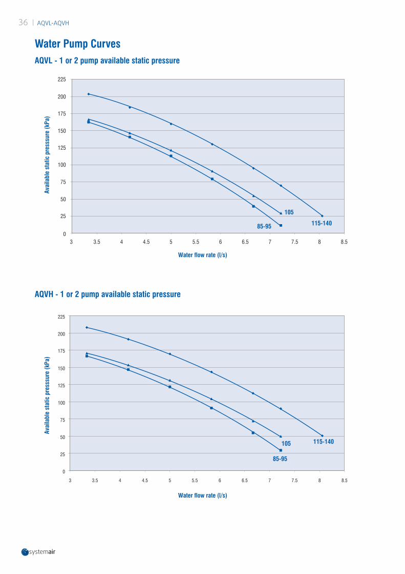
| AQVL-AQVH36
Water Pump Curves
3 3.5 4 4.5 5 5.5 6 6.5 7 7.5 8 8.50
25
50
75
100
125
150
175
200
225
85-95
105
115-140
0
25
50
75
100
125
150
175
200
225
3 3.5 4 4.5 5 5.5 6 6.5 7 7.5 8 8.5
85-95
105 115-140
AQVL - 1 or 2 pump available static pressure
AQVH - 1 or 2 pump available static pressure
Water flow rate (l/s)
Water flow rate (l/s)
Avai
labl
e st
atic
pre
sssu
re (k
Pa)
Avai
labl
e st
atic
pre
sssu
re (k
Pa)

AQVL-AQVH | 37
5698
856
1100
7098870 988
2256262 1612 382
P2
P1
P4
P3
2185
304
802
2555
369
250 575 580
230
208300
150
250
965
1041
1955
40
AE-F
B C
D
N
O
53 531100
1250 (Only for shipment)
4 x
50
G
H
I
L
M
4921382382 3010
4030
4x 17P4
P3
P2
P1
E-F
Bottom view
Side view
Top view
Front view
Dimensions (mm) - AQVL/AQVH - R410A - Sizes 85 to 115
A Water connection Ø 2 1/2" gas maleB Water connection Ø 2 1/2" gas maleC Water connection Ø 2 1/2" gas maleD Water connection Ø 2 1/2" gas maleE Electrical auxiliary linesF Electrical power supplyG High pressure tapH Low pressure tapI Gauge kit (accessory)L Main switchM Control keypad / display
N Desuperheater water inlet Ø1" gas male (optional)O Desuperheater water outlet Ø1" gas male (optional)
XXX Only for HPF fan modelP1, P2, P3, P4 AVM position
Hydraulic option Water in Water outSTD A B
1P/2P/3P C B1P+T/2P+T C D

| AQVL-AQVH38
Dimensions (mm) - AQVL/AQVH - R410A - Sizes 125 & 140
53 531250(Only for shipment)
I
G
H
L
M
4x50
802
304
250
369
230
208380
1180575
3155
250
150
965
1625
E-F
N
O
AB C
D
2856
7098870 988 5698
856
1100
262 2212 382P1
P2
P3
P4
382 1982 492 3010
4030
E-F
P1
P2 P4
P3
4x 17
Bottom view
Side view
Top view
Front view
A Water connection Ø 2 1/2" gas maleB Water connection Ø 2 1/2" gas maleC Water connection Ø 2 1/2" gas maleD Water connection Ø 2 1/2" gas maleE Electrical auxiliary linesF Electrical power supplyG High pressure tapH Low pressure tapI Gauge kit (accessory)L Main switchM Control keypad / display
N Desuperheater water inlet Ø1" gas male (optional)O Desuperheater water outlet Ø1" gas male (optional)
XXX Only for HPF fan modelP1, P2, P3, P4 AVM position
Hydraulic option Water in Water outSTD A B
1P/2P/3P C B1P+T/2P+T C D

AQVL-AQVH | 39
Space requirements (in mm)Installation of single unit
Installation of several units
A and C grilleB and D full
A and B fullC and D full
A and C fullB and D grille
A and B grilleC and D full
A and D grilleB and C full
A1 A2 A3 A1 A2 A3 A1 A2 A3 A1 A2 A3 A1 A2 A3ARRANGEMENT 1 1000 1000 1000 1000 800 800 1000 800 800 1000ARRANGEMENT 2 1000 1500 1000 1000 2000 1000 800 2000 800 1000 1500 800 800 1500 1000
No more than one wall can be higher than the unit.The area enclosed by the wall must be kept clear of all obstructions that would impede air flow to the unit. Dimensions in mm.
1.0 m
1.5 m
2.0 m
A1 A2
1.5 m
1.0 m
A2 A3A1
WALL A
WALL D WALL B
WALL CWALL C
WALL A
WALL D WALL B
ARRANGEMENT 1 ARRANGEMENT 2

www.systemair.com
Syst
emai
r · J
anua
ry 2
021
· EDM
AQ
V-S.
2GB/
01.2
1As
par
t of o
ur o
ngoi
ng p
rodu
ct im
prov
emen
t pro
gram
me,
our
pro
duct
s ar
e su
bjec
t to
chan
ge w
ithou
t prio
r not
ice.
Non
con
trac
tual
pho
tos.
Systemair srlVia XXV Aprile, 2920825 Barlassina (MB) Italy
Tel. +39 0362 680 1Fax +39 0362 680 693