Aquifer 200 and Aquifer 360 Manual...6 Introduction to the Aquifer 200/360 Originally developed for...
41
1 Katadyn Desalination, LLC Spectra Watermakers PH 415.526.2780 FX 415.526.2787 www.spectrawatermakers.com Revised 06.01.2014 Aquifer 200 and Aquifer 360 Manual
Transcript of Aquifer 200 and Aquifer 360 Manual...6 Introduction to the Aquifer 200/360 Originally developed for...

1
Katadyn Desalination, LLC Spectra Watermakers PH 415.526.2780 FX 415.526.2787 www.spectrawatermakers.com Revised 06.01.2014
Aquifer 200 and Aquifer 360 Manual

2

3
Table of Contents
Installation
Operation
Getting Started ................................................................................................................ 5 Introduction .................................................................................................................... 6 Feed Side Piping Schematic ............................................................................................. 7 Product Piping Schematic ................................................................................................ 8 Setting Up the Aquifer 200 .............................................................................................. 9 Electrical ........................................................................................................................ 10
Page Number
New Systems Start Up and Testing ................................................................................ 11 Normal Operation ......................................................................................................... 12 Maintenance ................................................................................................................. 18
Service & Maintenance Short Term Storage Procedures ..................................................................................... 15 Introduction to Spectra Chemicals……………………………………… ....................... …………...…..16 Long Term Storage ........................................................................................................ 17 Winterizing .................................................................................................................... 18 Maintenance………………………………………………………………………… ................................. ……19 Membrane Cleaning ...................................................................................................... 20 Suggested Spares........................................................................................................... 22 Troubleshooting………………………………………………………………………… ................................ ..23 Poor Water Quality ........................................................................................................ 24 Flow Test ....................................................................................................................... 25 Service Bulletins ............................................................................................................ 27 Plastic Tube Fitting Instructions……………………………………………………… ......................... ….32 High Pressure Tube Fitting Assembly Instructions………………………… ..................……………33 Parts breakdown for Aquifer systems ............................................................................ 34

4

5
Unpack the system and inspect it to make sure that it has not been damaged in shipment. Refer to the shipping list for your system to make sure you have received all of the compo-nents listed. Do not discard any packaging until you have found and identified all of the parts. The small installation parts are listed on the kit list. Warning! Spectra Watermakers will not be held responsible for shortages and or freight damage that are not reported within thirty days of the ship date. Study the system layout diagram, component photos and descriptions before beginning your installation. This will assist you in understanding the function of each component.
Getting Started
Aquifer Shipping List
Aquifer Portable Watermaker in Pelican Case
Suction hose (25’) with strainer and Banjo connector (1)
Brine discharge hose (25’) with Banjo connector (2)
Hand held Salinity monitor 1/4 product tubing (25’) (3)
1
2 3
Solar panel cable extender (Power Pack Solar models only)

6
Introduction to the Aquifer 200/360
Originally developed for ocean voyaging yachts, the Spectra Aquifer 200/360Portable Water-maker is both a desalinator and a water purifier. It is capable of producing high quality, good tasting drinking water from a variety of water sources including sea water, river water, lake water, or water from a brackish or contaminated well. It will effectively separate out salts, or-ganic chemicals, insecticides and pesticides, parasites and their cysts, bacteria, and viruses. It does not remove non-ionized heavy metals. The watermaker pumps approximately 1.5 gallons (6 liters) of feed water per minute to the reverse osmosis membrane. Ten (Aquifer 200/360) percent of this water passes through the membrane(s) as purified product water and the remaining water is returned to the feed water source as concentrated brine. The brine contains whatever was separated from the product water by the membrane and nothing is retained inside the machine. Feed water is filtered using a three-stage process. A strainer first keeps out large debris, and keeps the suction hose several inches off the bottom, then the water passes through an 80 mesh screen, then a 5 micron pre-filter protects the Clark pump from silt, algae and abrasive particles. The basic Aquifer is configured to run directly from a DC power source (12 or 24 Volt). Aquifer Power Pack versions are equipped with a battery and battery charger, which can be connected to any AC source. Aquifer Power Pack Solar versions also come with a collapsible solar panel. If the battery is fresh and fully charged the watermaker can be operated directly from the battery for two or more hours without an external power source. In order to prevent damage to the watermaker, the feed water should never contain chlorine, bleach, or any other strong oxidizer, which will damage the membrane. The watermaker should never be used with feed water saltier than sea water, such as is found in the Great Salt Lake, as operating pressures will be too high. Oil in the feed water will also damage the mem-brane.
Fold-out prefilter
Battery Charger
Feed Pump with battery underneath
Solar regulator
Membrane and pressure vessel
Clark Pump
Accumulator
**Model shown is Aquifer Power Pack Solar, with all possible options.

7
Feed Water Strainer and Screen
5 micron filter and housing
Spectra Clark Pump and Membrane assembly.
Pressure Relief Valve
Brine Outlet
Aquifer 200/360Feed Plumbing Schematic
Quick Disconnect
Pressure Gauge
Accumulator
Feed Pump
Product Water Outlet

8
Product Flow meter
Product Water Schematic
Product Outlet. DO NOT! feed the product into a vent line, manifold or the bottom of a tank. Make sure that there is no re-striction in this piping. Pressure in the product tubing must never exceed 5psi (0.3bar) at any time, (running or stopped) or the membrane will be permanently damaged.
There are four product water ports (2 in each end cap)
Clear product water tubing with quick-connect
9
SETTING UP THE AQUIFER 150/200/360
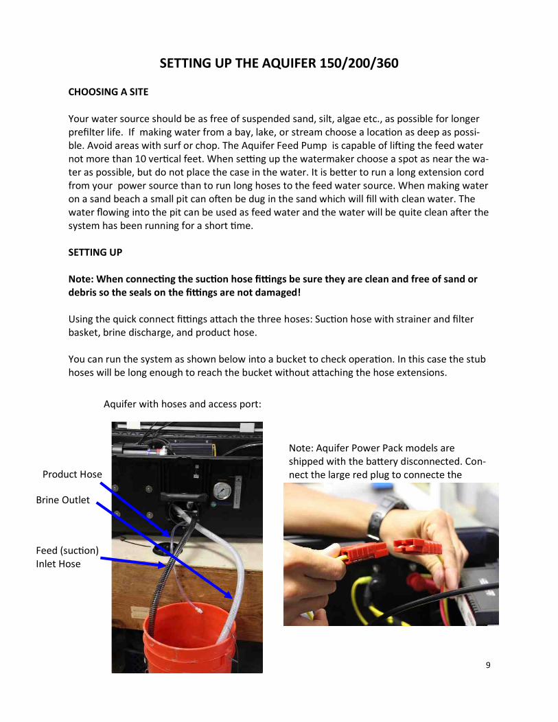
CHOOSING A SITE Your water source should be as free of suspended sand, silt, algae etc., as possible for longer prefilter life. If making water from a bay, lake, or stream choose a location as deep as possi-ble. Avoid areas with surf or chop. The Aquifer Feed Pump is capable of lifting the feed water not more than 10 vertical feet. When setting up the watermaker choose a spot as near the wa-ter as possible, but do not place the case in the water. It is better to run a long extension cord from your power source than to run long hoses to the feed water source. When making water on a sand beach a small pit can often be dug in the sand which will fill with clean water. The water flowing into the pit can be used as feed water and the water will be quite clean after the system has been running for a short time. SETTING UP Note: When connecting the suction hose fittings be sure they are clean and free of sand or debris so the seals on the fittings are not damaged! Using the quick connect fittings attach the three hoses: Suction hose with strainer and filter basket, brine discharge, and product hose. You can run the system as shown below into a bucket to check operation. In this case the stub hoses will be long enough to reach the bucket without attaching the hose extensions.
Aquifer with hoses and access port:
Brine Outlet
Feed (suction) Inlet Hose
Product Hose
Note: Aquifer Power Pack models are shipped with the battery disconnected. Con-nect the large red plug to connecte the

10
Electrical
On Power Pack models there is a 15-Amp fuse, in a water-tight holder, along the positive battery wire.
The battery charger included with Power Pack models accepts input voltages from 100-260 Volts AC, 50/60Hz. Connector supplied is for US-style 110V AC. Other con-nectors may be attached to the input
On Power Pack models with solar panel in-cluded, the panel fits into the lid of the case, and must be removed, unfolded, and connect-ed to the solar regulator
Solar regulator:
Solar panel connects to regulator with supplied 8-foot stub cables, and may be extended an additional 15-feet with the extension cables pictured on page 5:

11
Warning! Your watermaker shipped from the factory with a non-toxic potable water system preservative. Damage may occur if this preservative is not flushed out and the membrane is pressurized with preservative in it. DO NOT OPERATE the Aquifer system if the feed water could contain oil. 1. First:
You will need at least 50 gallons (200 liters) of salt, brackish, or fresh water. If the water has been chlorinated or chemically treated, replace the 5 micron filter with a Spectra Watermakers Charcoal Filter element during the flush.
Install the feed , brine, and product Hoses. Place the strainer end of the Feed Water Hose into the feed water source far enough below the surface to prevent air from being pulled in. Place the end of the brine hose so that the brine does not mix directly back in with the feed water.
Install the product hose and place the end of it so that any product will be discarded Ensure that the pressure relief valve is open 1/2 turn. Plug in the AC power cord, connect solar panel, or ensure that the battery is fully charged.
2. Turn on the feed water pump. Check that it is primed by inspecting the brine discharge. About 1.5 gpm (6 lpm) of water should be being discharged with a pulsation every few sec-onds.
3. Run the system without pressure for 20 minutes to purge the storage chemicals (4-6 hours if stored with propylene glycol). The system should have an open flow pressure on the gauge of about 20 PSI (1.2 bar). Water may drip from the product tube.
4. Close the pressure relief valve. The pressure should rise to 60-80 PSI (4.2-5.7 bar) if the feed water is sea water. If the feed water is brackish or fresh the pressure will be lower. After several minutes, water should begin to flow out of the product water tube.
5. Allow the system to run for 5-10 minutes to purge the product water of preservative, and then test the product with your handheld salinity tester. When the product is below 750 PPM it is considered potable and may be diverted to the water container for human con-sumption.
Aquifer New System Start-Up and Testing
Open 1/2 Turn to Purge Preservative! Remove Tag and Washer!

12
Normal Operation From a Large Body of Water If the system has been pickled or stored or contains cleaning compounds, use the “New Sys-tem Startup” procedure. 1. Any source of oil-free feed water not saltier than sea water may be used. Do not use wa-
ter containing large amounts of heavy metals, such as mine tailing runoff. 2. Set up the product tubing so that the product can be sampled. 3. Start the feed pump and check for flow by inspecting the brine discharge or checking for
pressure on your pressure gauge. If there is no flow, open the pressure relief valve one turn to bleed the air out of the feed pump, when there is good flow close valve
4. Check the product water with your handheld salinity tester. When it is below 750 ppm, you may divert it into your container, the water quality will improve as the system runs.
5. Run the system until you have filled your container or have made enough to meet your requirements for several days.
6. Monitor the feed water pressure. Make a note of the feed pressure with a clean filter ele-ment and change the filter if the pressure rises more than 5 psi (0.3 bar).
Shutting Down 1. You will need 3 gallons of water in a container, which will be used to flush the salt water
out of the watermaker. Use only unchlorinated water for flushing 2. Install the intake service hose and place it in the bucket. Start the feed pump. 3. Flush for 2 1/2 minutes or until the pressure drops on the gauge indicating that the mem-
brane is flooded with fresh water. Stop the feed pump. 4. Disconnect and stow the hoses. Put the plugs in the hose connections. You may now leave the system unattended for up to five days without further attention. We recommend operating the system for longer periods as you need to run the system almost a half an hour to make enough water to flush the system, and the system should be flushed after every use. You may notice that the system output is higher while charging your batter-ies, as the machine is voltage sensitive. Always ensure that the battery is fully charged after the watermaker is shut down to extend battery life.
Aquifer 200/360Operation
On/Off Switch
Flow Meter
Inlet Pressure Gauge
Brine Outlet
Feed Water Inlet
Product (Fresh) Water Outlet
13
Aquifer Operation continued...
Purifying Fresh or Brackish Water From a Tank or Well If the system has been pickled or stored or contains cleaning compounds, use the “New System Startup” procedure. 1. Fill the tank if necessary. Extremely hard water may cause scale buildup, requiring more
frequent cleaning. Do not use water containing large amounts of heavy metals, such as mine tailing runoff.
2. Set up the product tubing so that the product is being discarded and can be sampled. 3. Place the feed and brine hoses into the tank or well with the feed strainer near the
bottom and the brine discharging near the top. 4. Start the feed pump and check for flow by inspecting the brine discharge or checking for
pressure on your pressure gauge. If there is no flow open the pressure relief valve on the Clark Pump and bleed the air out of the feed pump.
5. Check the product water with your hand held salinity tester. When it is below 750 PPM, you may divert it into your fresh water container.
6. Watch the feed water level and the pressure gauge carefully. If the water level drops too far, add more water. If the pressure gauge reading rises above 80 PSI the dissolved solids concentration in the remaining feed water has risen too high. Discard this concentrated brine and refill the tank or well. The remaining concentrated feed can be pumped out by removing the brine hose from the water source and allowing the brine to be discharged into a drain.
Shutting Down 1. Make about 3 gallons of water into a bucket. This water will be used to flush the salt wa-
ter out of the watermaker. Use only unchlorinated water for flushing 2. Install the intake service hose and place it in the bucket. Start the feed pump. 3. Flush for 2 1/2 minutes or until the pressure drops on the gauge indicating that the mem-
brane is flooded with fresh water. Stop the feed pump. 4. Disconnect and stow the hoses. Replace the plugs in the hose connections. You may now leave the system unattended for up to five days without further attention. We recommend operating the system for longer periods and effecting a fresh water flush rather than running the machine every day and not flushing the system. Remember that you need to run the system almost a half an hour to make the flushing water. You may notice that the system output is higher while charging your batteries as the machine is voltage sen-sitive. Always ensure that the battery is fully charged after the watermaker is shut down to extend battery life.

14
Aquifer Operation continued...
Purifying Salt Water From a Container If the system has been pickled or stored or contains cleaning compounds, use the “New System Startup” procedure. 1. Set up a system to supply feed water to the container. 2. Set up the product tubing so that the product is being discarded and can be sampled. 3. Place the feed and brine hoses into the container with the feed strainer near the bottom
and the brine discharging near the top. 4. Start the feed pump and check for flow by inspecting the brine discharge or checking for
pressure on your pressure gauge. If there is no flow open the pressure relief valve on the Clark Pump and bleed the air out of the feed pump.
5. Check the product water with your hand held salinity tester. When it is below 750 ppm, you may divert it into your container.
6. Watch the feed water level and the pressure gauge carefully. 7. When the pressure gauge reading rises above 80 psi the dissolved solids concentration in
the container’s water has risen to high. Discard some of this concentrated water by re-moving the brine hose from the container and allowing the brine to be discharged into a drain. Refill the container.
Shutting Down 1. Make about 3 gallons of water into a bucket. This water will be used to flush the salt wa-
ter out of the watermaker. Use only unchlorinated water for flushing 2. Install the intake service hose and place it in the bucket. Start the feed pump. 3. Flush for 2 1/2 minutes or until the pressure drops on the gauge indicating that the mem-
brane is flooded with fresh water. Stop the feed pump. 4. Disconnect and stow the hoses. Replace the Plugs in the hose connections. You may now leave the system unattended for up to five days without further attention We recommend operating the system for longer periods and effecting a fresh water flush rather than running the machine every day and not flushing the system. Remember that you need to run the system almost a half an hour to make the flushing water. You may notice that the system output is higher while charging your batteries as the machine is voltage sen-sitive. Always ensure that the battery is fully charged after the watermaker is shut down to extend battery life.

15
Short Term Storage
Fresh Water Flush The purpose of the fresh water flush is to replace the sea water in the watermaker with fresh water whenever the system is not operating. The watermaker will last longer and operate better if it is always filled with fresh water between uses. If the watermaker is not used for more than five days it should be flushed again to ensure that the water inside stays fresh and oxygenated. In this way, the water maker can be kept ready for immediate use indefinitely. To make the watermaker ready for periodic fresh water flushing, put a Spectra Watermakers Charcoal Filter in the filter housing. The Charcoal filter will remove any damaging chlorine that might be present in the flush water. After five days, if the watermaker has not been used, put three gallons of fresh water in a bucket. Put the feed service hose in the bucket and the brine and product hoses to drain. Turn on the feed pump and run the watermaker until all the water has been pumped out of the bucket. Charge the battery. Remove the hoses, drain them, and stow them away in the case. Insert the hose connection plugs in the hose fittings. Leave the charcoal filter in the housing for next time. Charcoal filter elements are only good for six months after they are installed. After six months the charcoal filter element will lose its ability to remove chlorine.

16
INTRODUCTION TO SPECTRA CHEMICALS
We use four types of chemicals: SC-1, SC-2, SC-3, and propylene glycol antifreeze. SC-1 and propylene glycol are for system storage, while SC-2 and SC-3 are for membrane cleaning. Note: Never use any chemicals with the system pressurized! Always open the pressure relief valve 1/2 turn. Always follow the instructions for purging the chemicals as shown in the New System Startup section of your owner’s manual.
Storage: SC-1 prevents biological growth when your system is idle. It should not be used as a cleaning chemical, nor will it protect your system from freezing. A jar of SC-1 is mixed with 1 to 2 gallons of product or dechlorinated fresh water in a bucket and circulated through the sys-tem for 10 minutes. This treatment will protect the system for six months, after which the SC-1 treatment must be repeated. To use SC-1, follow the instructions for Ventura MPC Storage Procedure on the following page. Spectra systems should be stored with propylene glycol if freezing is likely to occur. This is a food grade antifreeze used to winterize RV’s, boats, and cabins. Propylene glycol also works very well for preventing biological growth in warm climates and is good for one year. See Win-terizing with Antifreeze (OP-1 document on the Spectra website). Note: Do not use metasodium-bisulfate, Citric Acid, or any other storage chemical not sup-plied by Spectra. These chemicals, used to store other watermaker brands, are very acidic and will damage the Clark Pump and void the warranty.
Cleaners: Cleaning can be detrimental to the membrane and shorten its life. Avoid unneces-sary cleaning, and avoid cleaning as a diagnostic tool. SC-2 is an alkaline cleaner used to remove light oil, grime and biological growth. It is most effective if heated to 120 deg. F, which is difficult on a boat. In most cases the water quality will increase in PPM (salinity) after an SC-2 cleaning. After a few hours it should recover to near the level it produced before the cleaning.
SC-3 is an acid cleaner used to remove mineral and scale deposits. In most cases this is used first and if there is no improvement, go on to the SC-2. SC-3 will in most cases lower the prod-uct PPM and overall pressures. Scaling is a slow process that may take several months or years. SC-3 is less harmful to the membrane and will almost always improve the performance of an older membrane. For cleaning with either SC-2 or SC-3, see the Cleaning Procedure.

17
Long Term Storage Procedures
Watermakers are best run continuously. When not in use, biological growth in the membrane is the leading cause of membrane fouling. A warm environment will cause more growth than a cold environment. If the system is to be left unused for more than five days, perform the follow-ing storage procedure. The procedure introduces a chemical compound into the system that prevents biological growth. This procedure requires de-chlorinated wa-ter. Spectra SC-1 a special storage compound, formulated to be compati-ble with the modern engineering plastics and composites in the Spectra pumps. Do not use any substitute except propylene glycol. If you wish to use glycol for storage, follow the winterizing instructions. SC-1 storage compound must be mixed at a ratio of 1 container to 3 gallons (12L) of fresh water to have the proper solution for up to six months storage. Caution! Avoid contact with skin, eyes, or lungs with the storage chemi-cal.
Aquifer 200/360Storage Procedure The watermaker can be stored for periods up to six months using this procedure.
1. Make or buy 4 gallons of chlorine-free water and put it in a bucket. 2. Place the end of the feed hose in the bucket and the brine hose to drain. 3. Start and run the feed pump until you have one gallon of fresh water left in the bucket. 4. Mix 1 container of SC-1 storage compound with the water in the bucket and place the end
of the brine service hose in the bucket. 5. Make sure the pressure relief valve on the
Clark Pump is OPEN (unpressurized) by turning 1/2 turn counterclockwise 6. Turn on the feed pump. Circulate the storage
chemical in the system for approximately 10 minutes. Turn off the feed pump when fin-ished.
Clean Up Remove the 5 micron filter element from its housing and put in a dry one. Rinse and dry the inside of the case, being careful not to get water inside the pump motor. Charge the battery. Remove the hoses, drain them, and stow them away in the case. Insert the hose connec-
tion plugs in the hose fittings.

18
Storage and Winterizing with Antifreeze
The watermaker can be stored for up to one year in any climate using this procedure.
1. Put 3 gallons of chlorine-free fresh water into a bucket. Perform a fresh water flush as de-scribed in the normal operation section. Run the feed pump until the bucket is empty.
2. Pour 2 gallons of low temperature propylene glycol potable water system antifreeze into the bucket.
3. Make sure the pressure relief valve on the Clark Pump is OPEN (unpressurized) by turning it 1/2 turn counterclockwise. 4. Start and run the feed pump until anti-
freeze begins to come out of the brine dis-charge hose.
5. Stop the feed pump. Direct the brine out-put into the bucket. 6. Start the Feed pump and circulate the re-
maining antifreeze for a few minutes until well mixed.
7. Stop the feed pump and discard any antifreeze remaining in the bucket. 8. Blow out or drain the product tubing, as it will not contain antifreeze. 9. Leave the pressure relief valve open.
Clean Up Remove the prefilter from its housing and replace with a clean dry filter element. Rinse and dry the inside of the Aquifer case to prevent corrosion. Do not get the Feed pump
motor wet. Remove and drain the service hoses and stow them away in the case. Insert the hose con-
nection plugs in the hose fittings. Charge or remove the battery for storage.
Recommissioning
Propylene glycol can be difficult to flush from a membrane, especially after extended storage periods. This results in high salinity water (high PPM) and residual flavor in the product water. We recommend flushing the system WITH THE PRESSURE RELIEF VALVE OPEN for 4-6 hours after storage with propylene glycol—the longer the better. If, after extended flushing, you still experience low product water quality, cleaning with SC-2 usually removes all traces of propylene glycol and returns the salinity to the level it was before storage with propylene glycol. See the Cleaning Procedure on page 20.

19
Maintenance
The Seawater Strainer The sea water strainer’s stainless steel element should be inspected, opened, and cleaned as needed. Check frequently during operation.
The Prefilter
Service the prefilter on a regular basis. The pressure will rise on the pressure gauge when the filter becomes dirty. Extremely dirty filters will harm system performance and may cause the feed pump to cycle on the high pressure cut-out switch. Do not leave dirty filters in the ma-chine during long idle periods, as biological contamination will result. To service the filter, swing it out of the case, open the housing, and discard the old filter. Clean out the housing bowl, reassemble the housing with a new 5 micron filter element. Leave dry until next startup. Use only Spectra approved filters or you may void your warranty. The filter may be cleaned several times by soaking it in water in a bucket. Occasionally, lightly lube the filter housing O-ring with silicone grease.
General Periodically inspect the entire system for leakage and chafe on the tubing and hoses. Re-pair any leaks you find as soon as practical. Some crystal formation around the Clark Pump blocks is normal. Wipe down any salt encrusted areas with a damp cloth. If any rust ap-pears at the stainless steel fittings, clean them up promptly. Keep the inside of the case dry and salt free to protect the electrical components inside.
The Feed Pump and Clark Pump
The feed water pump and the Clark Pump require no routine maintenance except inspection for leaks. Tighten any hose clamps or fittings that show signs of leakage. The high pressure fittings threaded into the Clark Pump have O-ring seals with a straight thread. These should never leak and should never be over tightened. If one of the tube nuts starts to leak, it can be un-threaded, sealed with a bit of silicone grease or silicone seal, and tightened with two wrenches very tightly.

20
The Membranes The membranes need to be cleaned only when feed pressure begins to rise due to fouling or the product quality degrades. The primary causes of fouling are biological growth and scaling. Biological growth occurs when the system is left unused without flushing or pickling. Fouling from mineral scaling will form when the feed water is “hard” or high in carbonates. Very small “colloidal metal” and metal oxide particles can also plug the pores in the membrane. Monitor the product salinity and feed pressure for higher than normal readings for the existing condi-tions. Other conditions can cause high pressure such as cold feed water or clogged filters. Low product flow is usually due to low voltage, damaged feed pump or Clark Pump. Look for all other causes before cleaning the membrane. Membrane life can be shortened by excessive cleaning. There are two types of cleaners: acid and alkaline. The acid cleaner (SC-3) will remove mineral scaling. The alkaline cleaner (SC-2) is used to remove biological by-products, oil, and dirt parti-cles that get past the prefilters. If membrane performance is reduced and it has not been “pickled” recently, cleaning with both chemicals is recommended. The acid cleaner should be used first. Colloidal Metals and Metal Oxides are very difficult to remove. If the membrane fails to respond to both cleanings, this is an indication of another problem with the system, or that it is time to replace the membrane. Contact Spectra Watermakers before removing a membrane.
Membrane Cleaning For normal cleaning, the SC-3 Acid Cleaning Compound is used first, then the SC-2 Alkaline Cleaning Compound. If known bio-fouling is present, the SC-2 may be used first. Using hot wa-ter if possible, up to 120° (45C) is recommended, as it greatly enhances the ability of the clean-ers to do their jobs. If the history of the system is unknown or it has been left “unpickled” for an extended length of time and biological growth is present, it is recommended that the system is cleaned with SC-2, using an alternate source of unchlorinated fresh water before the system is run under pres-sure. A simple test can be performed to see if biological growth has occurred. Before running the system, remove the prefilter and examine its condition. If the housing is full of smelly dis-colored water, the system was not properly stored. Install a clean prefilter if it was bad. Next check the membrane. Attach the feed and brine service hoses and lead them to a bucket of clean de-chlorinated water. Open the pressure relief valve one turn, and manually run the sys-tem for 30 seconds. Examine the brine water: if it’s discolored and smells bad, perform an SC-2 cleaning with an alternate source of unchlorinated water before running the system pressur-ized. If the brine is fairly clean, the system can be purged, run normally, and checked for per-formance. Clean the membranes only if performance is reduced. Heating the water is preferable. One way to do this is to find a camp stove and use a large stainless steel pot to heat the solution in. The cleaning solution throughout the system will heat as it circulates in and out of the pot. An alternative is to heat the one or two gallons of initial water to 120° on a stove before mixing in the cleaner and circulating it into the system. Periodically stop and reheat the solution.

21
Spectra cleaning compound (SC-2 or SC-3) must be mixed with fresh water at a ratio of 1 container of compound to 3 gallons (12L) of unchlorinated water to have the proper solution. About two gal-lons (8L) of water is already present inside an Aquifer system. This water has to be figured into the mixture. An Aquifer system will use one container of compound.
Note: Procedures are the same for the SC-2 and SC-3 cleaners
Cleaning Procedure: 1. Make 4 gallons of water into a bucket or obtain 4 gallons of chlorine-free fresh water. 2. Flush the system as shown in the Normal Operation Section. Leave one Gallon of water
in the bucket. 3. Place the inlet service hose, brine discharge service hose, and product hose in the bucket. 4. Make sure that the pressure relief valve is OPEN (un-pressurized). 5. Mix the cleaning chemical in the bucket. 6. Start the system and circulate the chemical through the system for 20 minutes. 7. Allow the system to soak for an hour; more if the chemicals are cold. 8. Run the pump for another 20 minutes. 9. Stop the pump, replace the brine discharge hose and start the pump until the bucket is
empty. 10. Flush the system using the instructions for “New System Startup.”

22
Suggested Spares Short term use, weekends etc. We suggest a basic cruise kit A. This kit consists of six 5 micron filters, and 2 SC-1 storage chemicals. Use for 2 to 6 months at a time. Two basic cruise kits, one replacement feed pump head. Longer than 6 months Additional filters, Offshore Cruising Kit consisting of Clark Pump seals, O-rings, tools and membrane cleaning chemicals. One replacement strainer. Spectra Watermakers parts list: SC-1 STORAGE CHEMICAL KIT-CHEM-SC1 SC-2 CLEANER KIT-CHEM-SC2 SC-3 CLEANER KIT-CHEM-SC3 BASIC CRUISE A KIT-BCK-A 5 MIC FILTER FT-FTC-5 CHARCOAL FILTER FT-FTC-CC FEED PUMP HEAD PL-PMP-SFPH FILTER HOUSING O-RING SO-FHS-10H OFF SHORE KIT KIT-OFFSH 20” MEMBRANE FT-MB-20 SUCTION STRAINER KIT-AQ-ATNASSEM
Part Number
23
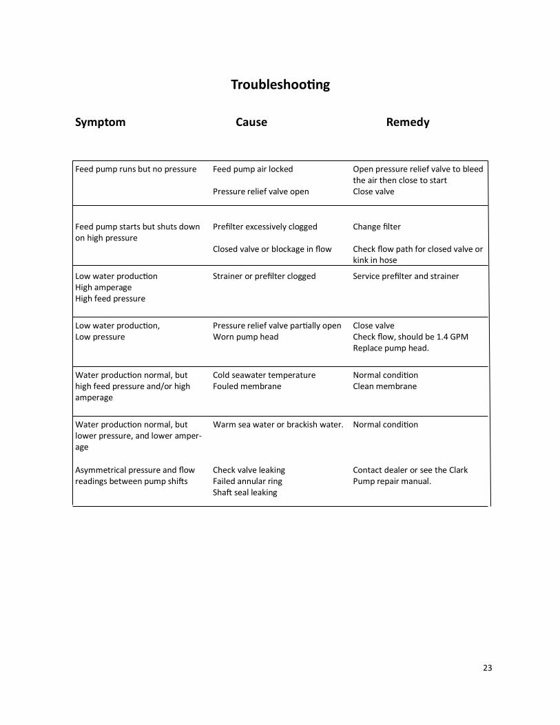
Troubleshooting
Symptom Cause Remedy
Feed pump runs but no pressure Feed pump air locked Pressure relief valve open
Open pressure relief valve to bleed the air then close to start Close valve
Feed pump starts but shuts down on high pressure
Prefilter excessively clogged Closed valve or blockage in flow
Change filter Check flow path for closed valve or kink in hose
Low water production High amperage High feed pressure
Strainer or prefilter clogged Service prefilter and strainer
Low water production, Low pressure
Pressure relief valve partially open Worn pump head
Close valve Check flow, should be 1.4 GPM Replace pump head.
Water production normal, but high feed pressure and/or high amperage
Cold seawater temperature Fouled membrane
Normal condition Clean membrane
Water production normal, but lower pressure, and lower amper-age
Warm sea water or brackish water. Normal condition
Asymmetrical pressure and flow readings between pump shifts
Check valve leaking Failed annular ring Shaft seal leaking
Contact dealer or see the Clark Pump repair manual.

24
Poor Product Water Quality
With any product water quality issue, you must ensure accurate calibration if you are using a salinity meter. For general quality evaluation, your taste is always good enough. Membranes are not an exact science and two identical systems can have different product quality. World health standards deem water of up to 1000 PPM of total dissolved solids ac-ceptable for drinking consumption. We consider any thing below 750 PPM acceptable but not ideal, and anything below 500 PPM excellent. Factors that could affect water quality are addressed below.
LOW SYSTEM FLOW OR PRESSURE will equate to lower product quality (higher PPM). Aq-
uifer systems, which have a higher feed to output pressure ratio (See nominal pres-sures under Flow Test), as well as a higher feed flow/membrane area ratio, will pro-duce water in the 150-200 PPM range.
DAMAGE TO THE MEMBRANE by chlorine contamination. Flushing the system with chlo-
rinated water will irreparably damage the membrane. Charcoal filters are used to ab-sorb any chlorine which might be present in flush water. They must be of proper specification to be suitable. There is no test for chlorine damage except the process of elimination of other causes.
DIRTY OR SCALED membranes. A dirty (foreign material), scaled (mineral deposits), or contaminated (bacterial growth) membrane can result in poor water quality and ab-normal operating pressures. If operating pressures are above normal, then cleaning is indicated. If the system pressures are within operating normal range, cleaning may have little result. Avoid cleaning as a diagnostic tool. Low water quality after storage with propylene glycol can usually be remedied by extended flushing or an SC-2 clean-ing.
MECHANICAL LEAKAGE within the membrane pressure vessel. This is an unlikely but pos-
sible cause of poor water quality with old style Codeline pressure vessels (white). The Spectra pressure vessel has a double O-ring arrangement that includes a telltale hole between them so that any salt water leaking past an O-ring will drip into the case and not go into the product water.
If system flow (product plus brine) is 1.5 GPM or above, the membrane is clean, the product flows are consistent with the system flow and the water quality is still not acceptable, then replacement of the membrane is indicated.

25
Aquifer Flow Test
The flow test is the most useful diagnostic test for system performance, and should be done before replacing or cleaning your membrane. Changes in production or water quality are nor-mally caused by something other than the membrane, unless the system has been left unused for a long time.
Before the flow test, change the filter and clean the sea strainer. Carefully check for water or air leaks, as air in the system will cause low production and erratic salinity. Look for air bubbles in the product flow meter, feed water hoses, and brine overboard hose. Run the system and watch the pressures very closely. If the feed pressure to the Clark Pump is asymmetrical from one stroke to another, this could be part of the problem. A difference of a few PSI is acceptable, but anything over that is an issue. If the pump is asymmetrical, Clark Pump repairs should be done before continuing with these tests. If no asymmetry is noted, continue with this test. Make sure the ShurFlo overpressure cutout switch (PL-PMP-SFPH) is set to 125 PSI. With the pump running, close the brine service valve. The feed pressure should rise to 125 PSI, then the pump should shut off. If the pump shuts off at a lower pressure see “SF-2 Adjust ShurFlo Pres-sure Switch,” later in this manual. You will need a graduated bucket and a stopwatch. Measurements must be very accurate, as errors of just a few percent will skew the results. Log the voltage at the feed pump at the same time. Confirm at least 12.5 volts at the pump on 12-volt systems. 1. First divert the product flow into the bucket and record how long it takes to accumulate a
given amount. Product flow is usually expressed in Gallons Per Hour or Liters Per Hour, so it’s easiest and most accurate to collect the flow for exactly ten minutes, then multiply the quantity by six to get GPH or LPH. Alternatively, you can collect exactly one gallon or four liters then calculate GPH or LPH as follows:
3600/time in seconds x quantity of water=GPH or LPH There are 3600 seconds in an hour. Example: It took 9 minutes, 45 seconds to collect 1 gallon of product water, so 3600/585 x 1 = 6.15 GPM (9 times 60 seconds is 540 plus 45 equals 585 seconds).

26
2. Divert the brine discharge, and the product water, both into the bucket. Feed flow (brine discharge and product combined) is usually expressed in Gallons Per Minute or Liters Per Minute. For the simplest and most accurate measurement, divert exactly 5 gallons or 20 liters, record the time, and calculate GPM or LPM as follows:
60/time in seconds x quantity of water = GPM or LPM Example: It took 3 minutes (180 seconds) to collect 5 gallons of feed flow, so 60/180 x 5 = 1.67 GPM
*pressure relief valve open ½ turn
In order to make good water, you need the proper amount of feed water flow, as in the table above. Compare the product flow to the total feed flow. Product flow should be 7% of total flow for an Aquirer 200, and 9.5% of total flow for an Aquifer 200. If product percentage is low, you may have an internal leak in the Clark Pump. For every 1/10
th of a GPM feed water flow loss, we will lose about 1/2 gallon per hour of product flow and the salinity will go up 100 PPM. Low feed flow combined with low system pressures is most frequently due to a worn ShurFlo pump head (PL-PMP-SFPH). 5/23/14
System
Feed Static * Feed Flow Product Flow
Pres-
sure
Pres-
sure Flow MIN MIN Flow Flow MIN MIN
psi bar psi gpm lpm gpm lpm gph lph gph lph
Aquifer 150 60-70 4.2-5 10-15 1.7 6.4 1.65 6.2 6.5 24.6 5.7 21.5
Aquifer 200/360 80-90
5.6-6.3 20-25 1.7 6.4 1.6 6.0 8.3 31.4 7.7 29.1

27
The following pages include Spectra’s most commonly used technical bulletins, covering tests, adjustments, troubleshooting, and common points of confusion.
MISC-1: DWYER FLOW METER SERVICE
The mechanical flow meter, PL-FMT-10 (10 GPH range) or PL-FMT-20 (20 GPH range) can be opened for cleaning if it becomes difficult to read or if the little ball gets stuck. The flow meter will come completely apart for cleaning. First remove the meter from the pan-el. Remove the four small screws that hold the stainless steel bracket in place. Carefully pry off the bracket. On the very top of the meter is a clear plastic slide-off cover over an Allen screw. Use a flat bladed screwdriver to push the cover off. Holding the meter upright, remove the Al-len screw with a ¼” Allen wrench. Invert the flow meter and catch the ball as it falls out. You can use tooth paste or plastic window polish to polish the inside using a small bottle brush. Clean the ball and give it a few coats of wax. If the o-rings are damaged or the unit has been leaking, install new o-rings using a little silicone grease to ease assembly. These are standard o-rings and should be available at most larger auto parts or bearing stores. Reassemble in re-verse.
MISC-3 ACCUMULATOR PRESSURE
Your Spectra Watermakers is supplied with a pressure accumulator tank (PL-ACC-TK), which should be installed in the feed water line between the prefilters and the Clark Pump. The purpose of the feed line accumulator is to reduce the spikes in the feed pressure caused by the cycling of the Clark Pump. If the accumulator is not properly charged it can lead to problems with the ShurFlo Pump pressure cutout switches. The accumulators have an air valve on top similar to those found on car tires. This allows the internal air bladder of the ac-cumulator to be pre-charged. The accumulator should be pumped up to about 65 psi (4.5 bar) for best results. Add air using a tire pump or air compressor. You can experiment with the ex-act pressure that will give the best pulsation dampening on your installation.
Technical Bulletins

28
PF-3 PREFILTERS– ShurFlo
An Aquifer system uses a single 5 micron filter to clean the feed water of abrasive materials while the system is in operation. A carbon filter may be used to prevent the entrance of chlo-rine during fresh water flushing. During normal operation, the feed water is filtered in two stages. First it passes through a fine mesh metal sea strainer, which protects the Feed Pump from foreign materials and larger sea creatures. After passing through the Feed Pump, the feed water passes the filter housing con-taining 5 micron element, removing very fine particles that could damage the Clark Pump and shorten membrane life. Cleaning schedules will vary widely depending on how and where the system is used. If large amounts of feed water are run through the system over a relatively short period of time in bi-ologically fertile near-shore waters, the prefilters will plug up, water production and quality will drop, and the system pressure will change dramatically. If the pressure gauge was installed before the prefilters, as pictured in this manual, the pressure will increase. If the pressure gauge was installed after the prefilters the pressure will drop When operated for only an hour or two a day in inland or near-shore waters, the trapped plankton will begin to decay in the filters long before the elements plug up. The decaying plankton and bacteria will cause a “rotten egg” smell in the product water. This decay will set in overnight in tropical waters, or after a week or two in higher latitudes. If handled gently and changed regularly before they get too smelly, filters can be cleaned several times. In crystal clear blue water conditions, the filters may need to be cleaned much less frequently. If a charcoal filter is used for fresh water flushing the system it will not plug up unless you have some incredibly dirty domestic water in your supply tank. About six months after installation the charcoal filter element will lose its effectiveness and must be replaced. This is purely a function of time.

29
PF-2: CHARCOAL FILTERS The charcoal filter element (FT-FTC-CC) removes chlorine from the fresh water flush water supply. The RO membrane can only handle small amounts of chlorine without permanent damage. If the fresh water flush water contains chlorine, the membrane will be exposed to it for days and will produce high salinity water. The charcoal filter we supply removes 99.7% of the chlorine. Beware when buying other char-coal filters. If they don’t specify the percentage of chlorine removed, don’t use them. Cheap ones may remove only 60% or 70%. Also, there are aftermarket filters which are very close to, but not exactly, the same dimensions that will not seal properly in the housing. If you skimp on the charcoal filter you risk damaging a $600.00 membrane on the first flush. The other fac-tor is the flow rate that the filter can handle. Because the chlorine is adsorbed by the char-coal, it must remain in contact with the charcoal for a sufficient period of time for the all of the chlorine molecules to be captured. The filters we use can handle 1.5 gallons (6 liters) per minute flow, and are good for 3000 gallons (12,000 liters) at 1.5 GPM, or six months, whichev-er comes first. Regardless of the flow the charcoal loses its effectiveness after six months. 5/23/14

30
SF-1: SHURFLO PUMP WON’T RUN
If the pump has power to it (the fan runs), but the pump won’t run, first check the pressure switch. The pressure switch (EL-FP-PS) is located on the wet end of the pump and has two red wires plugged into it. Jump the two red wires together and see if the pump runs. You can safe-ly run the system with the pressure switch jumped, just keep an eye on the pressure gauge and don’t let system pressure exceed 110 PSI. Replace the switch when a spare is available. The pressure switch should never open unless there is a problem with the system or it is incor-rectly adjusted. Check the accumulator pressure, the operating feed pressure, and the switch cut-out setting - bulletins: Misc-3, Misc-4, and SF-2. If the pump will not run with the pressure switch jumped then it is most likely a problem with the brushes or overheat protection switch inside the motor. The motor will come completely apart by removing the two screws on the end of the motor. Remove the rear cover and paper insulator. Pull out the plastic brush holder. The thermal switch is located on one of the brush leads. With an ohmmeter, check for continuity through the switch. If it is open, you can make temporary repairs by wiring around it, being careful that your new wiring doesn’t chafe on the moving parts, nor resist the springs that push the brushes on to the commutator. The overheat switch is unlikely to fail unless the motor has overheated and shut down. Consider relocating the pump or improving ventilation if the overheat protection has failed. If any corrosion is apparent the brushes may be sticking. Once apart clean all the carbon dust from all the parts. Clean the commutator with light sandpaper. Make sure to clean the small grooves on the commutator with a small sharp tool to remove the carbon in between the seg-ments. Adjust the springs on the brush holders so the brushes slide smoothly in and out. If the bearings are rough and binding, remove the rubber dust cover and clean the best you can, grease them, and work them free by hand. Don't service the bearing unless absolutely neces-sary. Reassemble in reverse order. You can hold the carbon brushes back with papers clips in-serted through the slots in the brush holder so they don't hang up on the bearing during as-sembly. Make sure the corrugated bearing shim doesn't push out, if it does, push it back into place. This may keep you going until the motor can be replaced. 5/23/14

31
SF-2: ADJUST SHURFLO PRESSURE SWITCH
The Shurflo feed pumps are equipped with a high pressure cut out switch (EL-FP-PS). This is the small black unit on the end of the wetted end of the pump head (PL-PMP-SFPH) where the two red wires connect. If the pressure switch is not properly adjusted the pump may cut out each time the Clark pump cycles and the feed pressure spikes. When this happens the produc-tion will drop and an unusual noise will be heard when operating on two pumps, but the sys-tem will function normally during one pump operation on either pump. The points in the switch will fail fairly fast if set too low because of the constant arcing from cutting out each time the Clark pump shifts.
For all systems except the Gulfstream the feed pump pressure switches should be set as fol-lows. On the very center of the switch is a small 5/64” Allen screw. Run the system on pump one and close the brine discharge valve (1/2 way 90 deg), or kink the discharge hose, to block the flow. Watch the pressure gauge and adjust the pressure switch to shut off at 125 psi. Re-peat for pump two. Turn the Allen screw clockwise to increase the cut off set point.
Gulfstream models could experience seal failures in the manifold if pressurized too high. For this reason the pump should be removed from the system and the switch adjusted using a separate pressure gauge. If replacing a feed pump or pump head for a Gulfstream model ar-range to preset the switch before installation.
5/23/14
Pressure Switch Adjusting Screw

32

33
Spectra High Pressure Tube Fitting Assembly Instructions The Aquifer has eight high pressure fittings, two on each cylinder on the Clark Pump, two on the pressure vessel end caps, and two 90-degree elbows on the back of the Clark Pump. As the compression fitting is tightened, it compresses a ferrule onto the stainless tubing, fixing the ferrule permanently to the tube and holding the compression nut captive. The body of the fitting seals to the underlying component with an O-ring. On the Clark Pump cylinders and the end caps this O-ring is compressed by tightening the entire fitting. The O-rings on the 90-degree fittings on the back of the Clark Pump have captive nuts and washers, which compress the O-rings without turning the entire fitting. If a tube fitting leaks it can sometimes be resealed by just tightening. You must use two wrenches, a 13/16-inch wrench to hold the base, and a 7/8-inch wrench to turn the compres-sion nut. The 13/16-inch wrench will need to be thin so as not to interfere with the compres-sion nut. If this doesn’t work, disassemble the fitting, grease liberally with silicone grease (the ferrule and the threads) and re-tighten firmly. The base O-rings should be gently compresses to achieve a good seal, and may be damaged by overtightening.
Stainless Fitting Hex Nut Connector O-RING Nickel-Bronze High Pressure Elbow
Nickel-Bronze High Pressure Straight Fitting
Ferrule
34
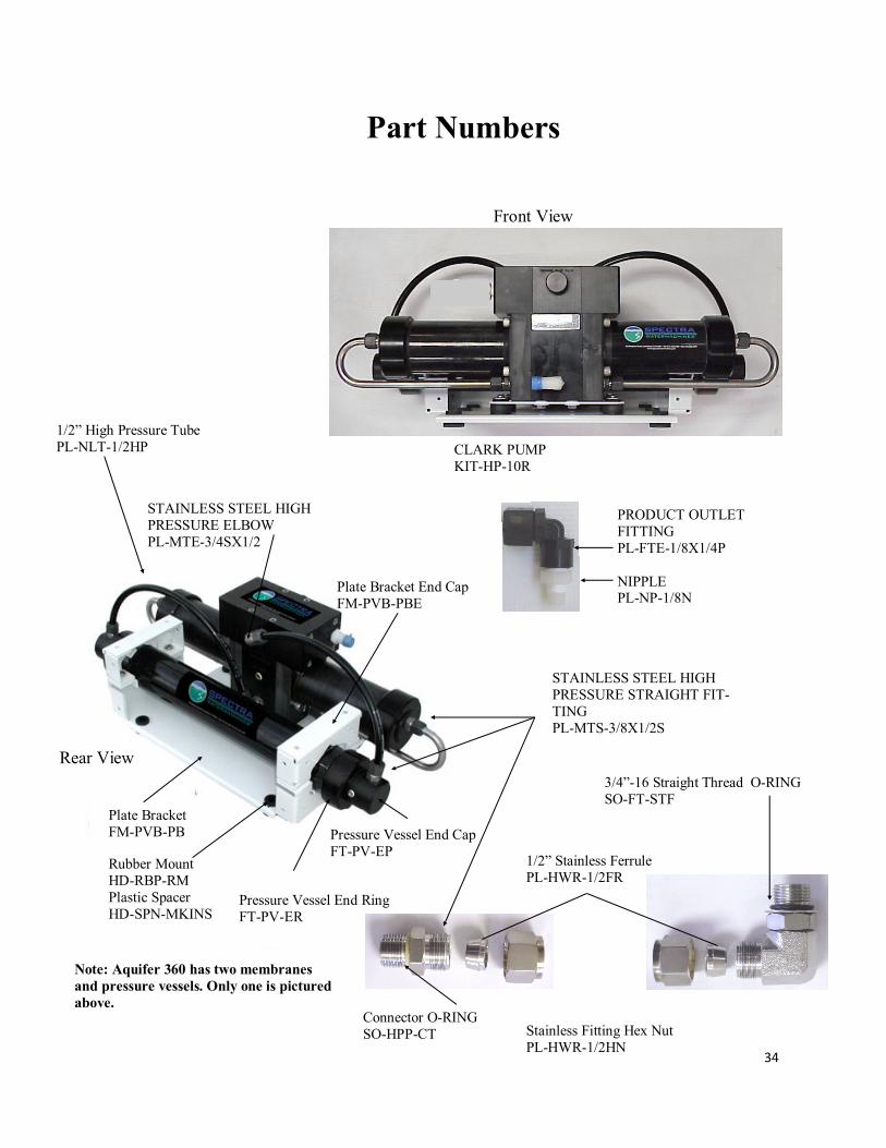
Front View
Rear View
Plate Bracket
FM-PVB-PB
Rubber Mount
HD-RBP-RM
Plastic Spacer
HD-SPN-MKINS
Plate Bracket End Cap
FM-PVB-PBE
Pressure Vessel End Cap
FT-PV-EP
Pressure Vessel End Ring
FT-PV-ER
1/2” High Pressure Tube
PL-NLT-1/2HP
Part Numbers
Stainless Fitting Hex Nut
PL-HWR-1/2HN
1/2” Stainless Ferrule
PL-HWR-1/2FR
Connector O-RING
SO-HPP-CT
3/4”-16 Straight Thread O-RING
SO-FT-STF
STAINLESS STEEL HIGH
PRESSURE ELBOW
PL-MTE-3/4SX1/2
STAINLESS STEEL HIGH
PRESSURE STRAIGHT FIT-
TING
PL-MTS-3/8X1/2S
CLARK PUMP
KIT-HP-10R
PRODUCT OUTLET
FITTING
PL-FTE-1/8X1/4P
NIPPLE PL-NP-1/8N
Note: Aquifer 360 has two membranes
and pressure vessels. Only one is pictured
above.
35
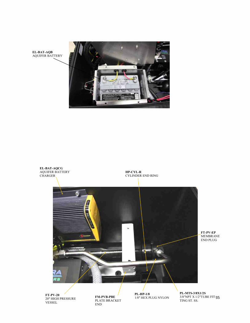
EL-BAT-AQB
AQUIFER BATTERY
EL-BAT-AQCG
AQUIFER BATTERY
CHARGER
HP-CYL-R
CYLINDER END RING
FT-PV-EP
MEMBRANE
END PLUG
PL-MTS-3/8X1/2S
3/8"NPT X 1/2"TUBE FIT-
TING ST. SS.
PL-HP-1/8
1/8" HEX PLUG NYLON FT-PV-20
20" HIGH PRESSURE
VESSEL
FM-PVB-PBE
PLATE BRACKET
END

36
PL-SWF-1/2X1/2
1/2"NPT X 1/4" TUBE
SWIVEL FITT ELL
PL-BSH-3/4X1/2N
3/4" X 1/2" HEX BUSHING
REDUCER NYL
FT-FTC-5
5 MICRON FILTER
ELEMENT (INSIDE)
FT-FTH-10H HIGH
PRESSURE FILTER
HOUSING(BLACK)
FM-PVB-PBE
PLATE BRACKET
END
EL-BAT-AQCG
AQUIFER BATTERY
CHARGER
PL-NLT-1/2HP
1/2" HIGH PRESSURE TUBE
(PARKER)
1/8" NPT X 1/4" HOSE BARB
ELL NYLON
PL-ACC-TK
ACCUMULATOR
TANK
PL-BSH-1/2X1/4N
1/2" X 1/4" HEX BUSHING
REDUCER NYL
EL-STK-VTOVL
VENTURA PANEL
OVERLAY
PL-PSG-LP2.5
2.5"D,1/4"NPT PRESS.
GAUGE 0-200PSI
PL-FMT-10
FLOW METER (10G)
PL-FTE-1/4X1/4P
1/4"FPT X 1/4"TUBE FITTING
ELL
PL-MTE-1/8X1/4P
1/8"NPT X 1/4"TUBE FIT-
TING ELL NYL
FM-AQ-FBF
FILTER BRACKET FIXED
AQUIFER PART NUMBERS
FM-AQ-FBH
FILTER BRACKET
HINGE
PL-SWF-1/2x1/2T
1/2”NPT x 1/2” TUBE
SWIVEL TEE POLY
PL-MTE-3/8x1/4J
3/8”NPT x 1/4” TUBE
FITTING ELL JG

37
1/8MPT X 1/4 TUBE EL
PL-MTE-1/8X1/4P
PRODUCT FLOW METER
PL-FMT-10
AQUIFER PART NUMBERS
PREFILTER HIGH
PRESSURE FILTER
HOUSING
FT-FTH-10H
5 MICRON FILTER
CARTRIDGE
FT-FTC-5
PRESSURE GUAGE
PL-PSG-2.5L
1/4FPT X 1/4 TUBE EL
PL-FTE-1/4X1/4P
ACCUMULATOR
PL-ACC-TK
1/2MPT X 5/8 HOSE
BARB PL-HBS-1/2X5/8
1/2” TEE
PL-TEE-1/2FN
1/2” NIPPLE
PL-NP-1/2N 1/4MPT X 1/4 TUBE
STRAIGHT FITTING
PL-MTE-1/4X1/4
1/2 X 1/4 BUSHING PL-BSH-1/2X1/4N
Fig 2 Fig 3
Feed Pump 12Volt,
EL-FP-12V
Feed Pump 24Volt
EL-FP-24V
3/8”NPT X 5/8” Hose Barb El.
PL-HBE-3/8X5/8
Pump Head Assembly W/Press. Switch
PL-PMP-SFPH
Feed Pump Pressure Switch
EL-FP-PS
SEA STRAINER
KIT-AQ-ATNASSEM

38
HP-TB-VEB-B
HP-TB-VB
HP-TB-VEB-A
HP-TB-BV
HP-CB-CB7,
HP-CYL-SST
HP-CYL-R
HP-CYL-EC
HP-CYL-CCA
Not used
39
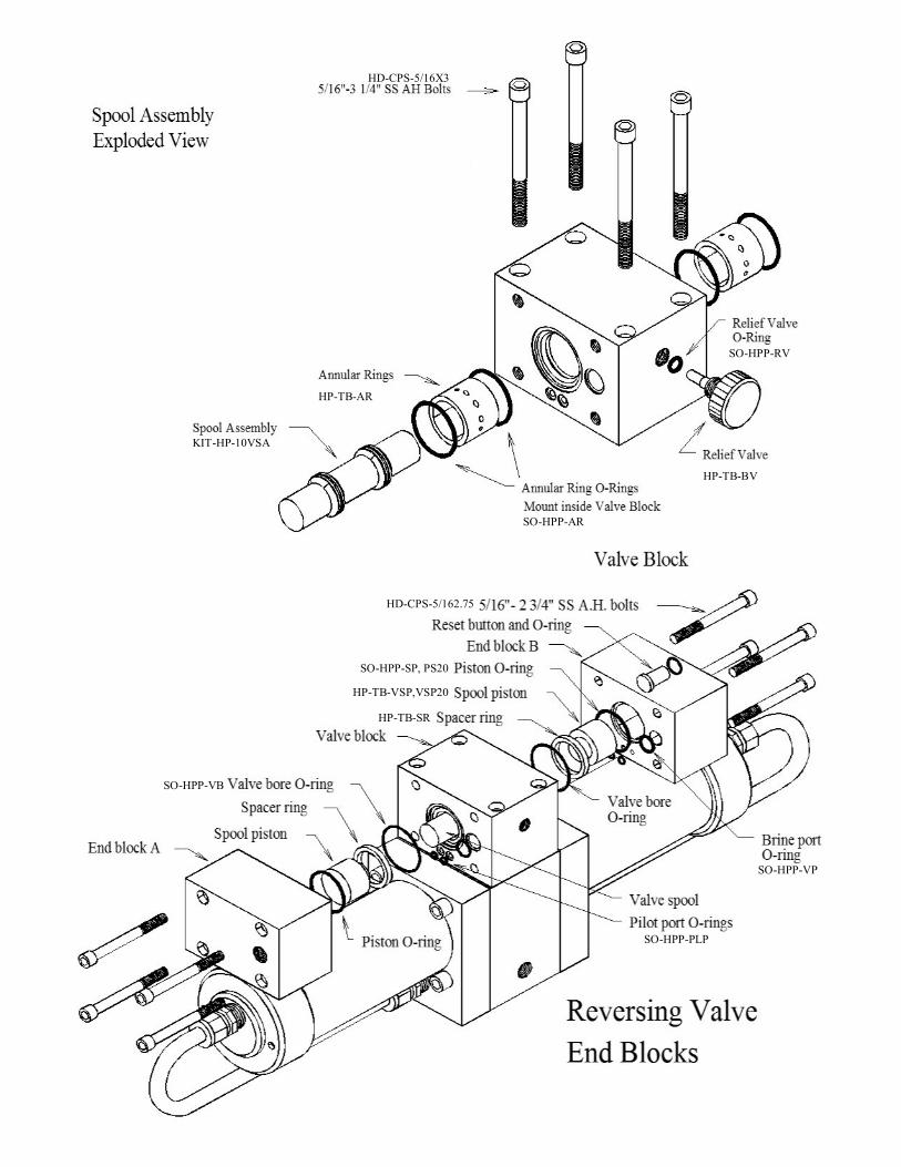
HD-CPS-5/16X3
KIT-HP-10VSA
HP-TB-AR
SO-HPP-AR
SO-HPP-RV
HP-TB-BV
HD-CPS-5/162.75
SO-HPP-SP, PS20
HP-TB-VSP,VSP20
HP-TB-SR
SO-HPP-VB
SO-HPP-PLP
SO-HPP-VP

40
Parts

41
PL-MTS-3/8X1/2S
HP-CYL-SST
HP-CYL-CCA SO-HPP-ECCB
HP-CYL-EC
HP-CYL-R
HP-CYL-PT
Parts