Applied Harmonics
24
HARMONICS Presented by: Syed Khundmir T Department of Electrical Engineering University at Buffalo [email protected] The BEST Group THE BUFFALO ENERGY SCIENCE AND TECHNOLOGY GROUP -Winter Lecture Series Prime reference: Electrical Power Systems Quality By Roger C. Dugan, Mark F. McGranaghan, Surya Santoso, H. Wayne Beaty
-
Upload
armando-malone -
Category
Documents
-
view
266 -
download
4
description
applied harmonics
Transcript of Applied Harmonics
HARMONICS
Presented by: Syed Khundmir T Department of Electrical Engineering University at Buffalo [email protected]
The BEST Group THE BUFFALO ENERGY SCIENCE AND TECHNOLOGY GROUP
-Winter Lecture Series
Prime reference: Electrical Power Systems Quality By Roger C. Dugan, Mark F. McGranaghan, Surya Santoso, H. Wayne Beaty

Harmonic Indices
• Total Harmonic Distortion (THD): It is the potential heating value of the harmonics relative to the fundamental of the quantity.
• Total Demand Distortion (TDD): It is the potential heating value of the harmonics relative to the peak demand load current.

Locating Harmonic Sources
Effect of Harmonic Distortion
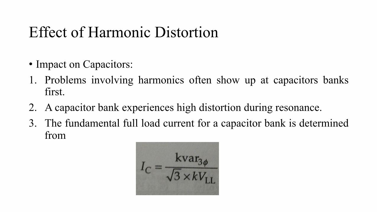
• Impact on Capacitors: 1. Problems involving harmonics often show up at capacitors banks
first. 2. A capacitor bank experiences high distortion during resonance. 3. The fundamental full load current for a capacitor bank is determined
from
Impact on Transformers
• Harmonic distortion of current and voltage will contribute significantly to additional heating. • Designers often put more cooling ducts in the transformers to
accommodate higher frequencies. • The harmonic currents increase rms current in a transformer resulting
in increased conductor losses. • Eddy current losses increase with the square of frequency of the
current and thus it is a very important component of transformer losses for harmonic heating.

Impact on Motors
• Harmonic voltage distortion at the motor terminals is translated into harmonic fluxes within the motor. • Harmonic fluxes do not contribute significantly to motor torque, but
rotate at a frequency different than the rotor synchronous frequency, basically inducing high-frequency currents in the rotor. • Decreased efficiency along with heating, vibration, and high-pitched
noises are indicators of voltage distortion. • Excessive heating problems begin when the voltage distortion reaches
8 to 10 percent and higher. Such distortion should be corrected for long motor life.
Impact on Telecommunications
• Harmonic currents flowing on the utility distribution system or within an end-user facility can create interference in communication circuits sharing a common path. • Triplen harmonics are especially troublesome in four-wire systems
because they are in phase in all conductors of a three-phase circuit and, therefore, add directly in the neutral circuit, which has the greatest exposure with the communications circuit. • The figure in the next slide illustrates coupling from the neutral of an
overhead distribution line by induction:


Impact on Energy and Demand Metering
• Electrical utility companies usually measure energy consumption in two quantities: The total cumulative energy consumed and the maximum power used for a given period. • Thus, there are two charges in any given billing period: Energy
charges and Demand charges. • Both energy and demand charges are measured using Watthour and
demand meters. • Harmonic currents from nonlinear loads can impact the accuracy of
watthour and demand meters adversely.
Contd…
• Conventional magnetic disk watthour meters tend to have a negative error at harmonic frequencies. • This error increases with frequency. • In general, nonlinear loads tend to inject harmonic power back onto
the supply system and linear loads absorb harmonic power due to the distortion in the voltage. • While the energy meter should be sufficiently accurate given that the
voltage has low distortion, the demand metering could have substantial error.
Harmonic Distortion Evaluations
• End users: For individual end users, IEEE standard limits the level of harmonic current injection at the point of common coupling (PCC). This is the quantity end users have control over. • The utility: Since the harmonic voltage distortion on the utility system
arises from the interaction between distorted load currents and the utility system impedance, the utility is mainly responsible for limiting the voltage distortion at the Point of Common Coupling (PCC)/ • For systems below 69kV, the THD should be less than 5%. • Thus, in principle, end users and utilities share responsibility for
limiting harmonic current injections and voltage distortion at the PCC.

Contd…
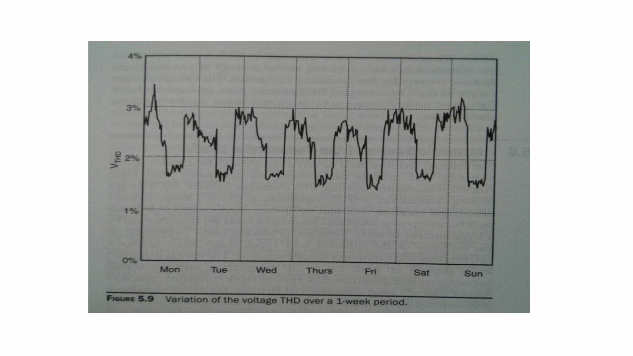
• The measurements should be taken continuously over a sufficient period of time so that time variations of harmonic distortions can be accurately represented. • The minimum measurement period is usually 1 week since this
provides a representative loading cycle for most industrial and commercial loads.

Concept of Point of Common Coupling
• Evaluations of harmonic distortion are usually performed at a point between the end user or customer and the utility system where another customer can be served. This point is known as the point of common coupling. • This point can be located at either the primary or secondary side of the
service transformer depending on whether or not multiple customers are supplied from the transformer.


Harmonic Evaluations on the utility system
• Harmonic evaluations on the utility system involve procedures to determine the acceptability of the voltage distortion for all customers.

Contd…
• The two important components for limiting voltage distortion levels on the overall utility system:
1. Harmonic currents injected from individual end users on the supply must be limited.
2. Harmonic current frequencies should not be in resonance with the system resonance frequency. It can result in unacceptable levels of voltage distortion at some system locations.

Principles of Controlling Harmonics
• Common causes of harmonic distortion: 1. The source of harmonic currents is too great. 2. The path in which current flow is too long, resulting in either high-
voltage distortion or telephone interference. 3. The response of the system magnifies one or more harmonics to a
greater degree than can be tolerated.

Contd…
• When a problem occurs, the basic options for controlling harmonics are:
1. Reduce the harmonic currents produced by the load. 2. Add filters to the siphon the harmonic currents off the system, block
the currents from entering the system, or supply the harmonic currents locally.
These options are briefly explained in the next slides:

Reducing harmonic currents in loads
• There is often little that can be done with existing load equipment to significantly reduce the amount of harmonic current it is producing unless it is being mis-operated. • While an overexcited transformer can be brought back into normal
operation by lowering the applied voltage to the correct range, arcing devices and most electronic power converters are locked into their designed characteristics. • Delta-connected transformers can block the flow of triplen harmonics
from the line whereas zigzag and grounding transformers can shunt the triplens off the line.

Filtering
• The shunt filter works by short-circuiting harmonics currents as close to the source of distortion as practical. This keeps the current out of the supply system. • This is the most common type of filtering applied because of
economics and because it also tends to correct the load power factor as well as remove the harmonic current. • Another approach is to apply a series filter that blocks the harmonic
currents. It offers a high impedance to the harmonic current.

Controlling harmonics on utility distribution feeders • The feeder banks should not be placed wherever they are needed without
concern about harmonics. • The usual strategy is to first attempt a solution by moving the offending
bank or changing the capacitor size or neutral connection. • Some harmonic problems associated with feeder capacitor banks are due to
increasing the triplen harmonics in the neutral circuit of the feeder. • These problems on distribution feeders often exists only at light loads. The
voltage rises, causing the distribution transformers to produce more harmonic currents. • Harmonic flow studies should always be performed when large capacitor
banks are installed in distribution substations since the magnification by resonance can be severe.

In End User facilities
• When harmonic problems arise in an end user facility, the first step is to determine if the main cause is resonance with the capacitors in the facility. The solution can be just replacing the current capacitor size. • In other cases, there will be so many capacitors switched at random
with loads that it will be impossible to avoid resonant conditions. Filtering will be necessary. • When magnitude of harmonic currents injected by loads is excessive,
industrial users should also investigate means of reducing harmonics by using different transformer connections and line chokes.
Conclusion
• Thus harmonics are significantly important part of any system study and should be kept in mind when building a new facility or adding a new capacitor in any system.