
Application Specific VLSI Processor Design For Parametric Speech
22
25 Chapter 2: Literature Survey 2.1 Review of ASIP-related Literature With the increasing interest in the ASIP design, many researchers have proposed several techniques for ASIP design. Techniques suggested by Sato et al. [14] and Gloria et al. [29] are among the earliest techniques and techniques suggested by Renhai et al [57], Fontaine et al. [58], David et al. [59] and Lee et al. [60] are the recent ones. In this Chapter a brief survey of ASIP design methodologies is presented. This helps in placing our work in the overall context. ASIPs are programmable processors with an instruction set and the underlying micro-architecture of the processor optimized for high speed real-time execution of a class of applications. The ASIPs bridge the gap between Application Specific Integrated Circuits (ASICs) and general-purpose programmable processors in terms of performance, power, cost and flexibility [24]. Due to their programmability ASIPs have a flexible functionality within their application domain and yet due to hardware optimization of their micro-architectures (that support execution of instructions) they achieve very high performance comparable to ASICs (which typically have a fixed functionality). Therefore for implementing system logic with a provision of easy upgradability and a desired kind of optimization among performance, power and cost, Application Specific Instruction set Processor (ASIP) based system logic implementation approach provides a powerful path. It is being projected that ASICs will be replaced by ASIPs in near future because it is getting harder and more expensive to design and manufacture ASICs [25]. Gloria et al. [29] suggested some of the main requirements for the design of Application Specific Architectures (ASA) as follows: Start design cycle with the description of behavior of the application (behavioral description) specified by means of a high-level languages. Identify hardware functionalities to speed up the application.
Transcript of Application Specific VLSI Processor Design For Parametric Speech
25
Chapter 2: Literature Survey
2.1 Review of ASIP-related Literature
With the increasing interest in the ASIP design, many researchers have proposed
several techniques for ASIP design. Techniques suggested by Sato et al. [14] and Gloria
et al. [29] are among the earliest techniques and techniques suggested by Renhai et al
[57], Fontaine et al. [58], David et al. [59] and Lee et al. [60] are the recent ones. In this
Chapter a brief survey of ASIP design methodologies is presented. This helps in placing
our work in the overall context.
ASIPs are programmable processors with an instruction set and the underlying
micro-architecture of the processor optimized for high speed real-time execution of a
class of applications. The ASIPs bridge the gap between Application Specific Integrated
Circuits (ASICs) and general-purpose programmable processors in terms of performance,
power, cost and flexibility [24].
Due to their programmability ASIPs have a flexible functionality within their
application domain and yet due to hardware optimization of their micro-architectures
(that support execution of instructions) they achieve very high performance comparable
to ASICs (which typically have a fixed functionality).
Therefore for implementing system logic with a provision of easy upgradability
and a desired kind of optimization among performance, power and cost, Application
Specific Instruction set Processor (ASIP) based system logic implementation approach
provides a powerful path.
It is being projected that ASICs will be replaced by ASIPs in near future because
it is getting harder and more expensive to design and manufacture ASICs [25].
Gloria et al. [29] suggested some of the main requirements for the design of
Application Specific Architectures (ASA) as follows:
Start design cycle with the description of behavior of the application
(behavioral description) specified by means of a high-level languages.
Identify hardware functionalities to speed up the application.

26
Evaluate several architectural options.
Introduce hardware resources for frequently used operation.
In the ASIP design, it is important to search for a processor architecture that
matches target application. To achieve this goal, it is essential to estimate design quality
of various candidate architectures in terms of their area, performance and power
consumption.
Typically ASIP design starts with analysis of the applications. Sato et al. [14]
reported an Application Program Analyzer (APA) in 1991. The output of APA includes
data types and their access methods, the frequency of individual operations and sequence
of continuous operations. The output of APA is used to define instruction-set.
More recently application analyzers such as those developed by Gupta et al. [47]
extract a larger number of application parameters. These include the average basic block
size, number of Multiply-Accumulate (MAC) operations, ratio of address computation
instructions to data computation instructions, ratio of input/output instructions to the total
instructions etc. Idea behind extracting these parameters is to make a decision about
inclusion of a hardware unit in the processor depending on the values of the above
mentioned application parameters. For example, if MAC operation is frequently used in
the application then it is useful to have a unit to perform this functionality in hardware.
Recently, Kolar et al. [61] have presented the concept of automatically generated
just-in-time translated simulator with the profiling capabilities. They have shown that this
simulator is very fast, generated in a short time and can be even used for simulation of
special applications such as applications with self-modifying code or applications for
systems with external memories.
Architectures considered by different researchers also differ in terms of the
instruction level parallelism they support. For example, Binh et al. [45] do not support
instruction level parallelism, whereas Gupta et al. [47] support VLIW architecture.
Binh et al. [16] suggested a HW/SW partitioning algorithm (branch-and-bound)
for synthesizing the highest performance pipelined ASIPs with multiple identical
functional units. Gate count and power consumption are the given constraints. They have
improved their algorithm considering RAM and ROM sizes as well as chip area

27
constraints [16]. Chip area includes the hardware cost of the register file for a given
application program with the associated input data set. This optimization algorithm
defines the best trade-offs between the CPU core, RAM and ROM of an ASIP chip to
achieve highest performance while satisfying design constraints on the chip area.
Huang et al. [12] have shown that instruction set can also be generated by
augmenting the instruction set with special instructions that are synthesized from scratch.
They considered the process of instruction set generation only after the parallelism and
functionality of the processor micro-architecture is finalized based on the application.
Gshwind [11] considered that the processor micro-architecture is fixed and only
the instruction set is generated within the flexibility provided by the micro-architecture.
Cong et al. [34] present an automated compilation flow for detection and
generation of application-specific instructions for ASIPs, based on pattern detection,
followed by instruction set selection guided by a cost function taking into account
occurrence, speedup and area costs.
Galuzzi et al. [62] present an algorithm for automatic selection of application-
specific instructions with hardware constraints.
Imai et al. [41] assumes that the instruction set can be divided into two groups:
operations and functions. The algorithm developed by Imai et al. [41] automate the
design of ASIP instruction set, as well as enabling designers to estimate the performance
of their design before implementation.
In ASIPs, the customization of the design is focused on the addressed application
domain - they are more specialized and therefore more optimized than PDSPs
(Programmble Digital Signal Processors), in terms of timing performance, energy
consumption and required area [25].
Fanucci et al. [25] have shown that Architecture Description Languages (ADLs)
offer the ASIP designer a quick and optimal design convergence by automatically
generating the software tool-suite as well as the Register Transfer Level (RTL)
description of the processor. Of course, while designing an ASIP, it is the designer’s duty
to do the trade-off of performance versus flexibility in the most suitable way. Depending
on the application, a more specialized or a more flexible ASIP may be desirable. The
flexibility provided by programmability comes with a performance and power overhead

28
[24]. ASIPs have the potential of requiring less area or power than general-purpose
processors. Hence, they are popular especially for low power applications.
Several techniques have been proposed to enhance the energy-efficiency of ASIPs
[37]. While those techniques can reduce the energy consumption with a minimal change
in the instruction set, they fail to exploit the opportunity of designing the entire
instruction set from the energy-efficiency perspective.
Renhai et al. [57] have designed the ASIP for AES based on the ESL (Electronic
System Level) methodology. In ESL based design flow, a commercial processor tool
based on Language for Instruction-set Architectures (LISA) is adopted. They have
developed several instructions on the basis of initial profiling of C description of AES.
They have implemented only four AES specific instructions.
David et al. [59] have presented a methodology using computer-aided design, for
development of high-performance Application Specific Instruction set Processor (ASIP)
targeting applications saturated in repetitive sequential bitwise operations and data-flow
dependencies, thus exposing both fine and coarse grain parallelism through a set of
recurring pattern extraction tools.
Fontaine et al. [58] have proposed a multiprocessor ASIP architecture based on
the Tensilica Xtensa processor for accelerating an implementation of 3D tracking
algorithm. They have used extensible architecture to implement custom instructions.
They have chosen a 3-processor architecture after the analysis of the algorithm and the
profiling results. Each processor is designed for a specific task: frame loading, target
tracking and target tracking with 3D calculations.
Guzma et al. [64] have presented an implementation methodology that leads from
an application specification in high level model of computation, Synchronous Data-flow
Graph, to an implementation as an application specific instruction set processor.
Lee et al. [60] have proposed a new application specific processor based on 6-
stage pipelined dual issue VLIW+SIMD architecture and compiler for efficient H.264
inverse transform and inverse quantization. The behavior, the structure, and the I/O
interface have been described using LISA (language for instruction set architecture).
Momcilovic et al. [64] have proposed a low power Application Specific
Instruction Set Processor (ASIP) to implement data-adaptive Motion Estimation (ME)

29
algorithms, that is characterized by a specialized data-path and minimum and optimized
instruction set. To support this instruction set, a simple and efficient micro-architecture
was also designed and implemented. Control signals are generated by a quite simple and
hardwired control unit. A set of software tools was developed and made available to
program ME algorithms on the proposed ASIP, namely, an assembler and a cycle-based
accurate simulator. The proposed architecture was described in VHDL and synthesized
for the UMC 0.13μm standard cell library.
Ragel et al. [65] have presented the impact of loop unrolling on the performance
(speed) of multi-pipeline ASIPs. They have presented how loop unrolling improves the
ILP (Instruction Level Parallelism) within loops of an application and therefore achieve
better overall performance.
During the literature survey we have observed that while significant work
has been done on the individual components of ASIP design e.g. instruction set
design/synthesis (from application analysis), the ASIP design implementations have
not been too many. Also in cases where implementations have been carried out,
commercial tools like LISA or ADL and commercial platforms like EXTENSA have
been used for implementations.
These implementations therefore appear to be constrained by the limitations
imposed by the tools and or the platforms used. While this may be agreeable from
an industrial perspective, it appears restrictively constraining from a research and
exploration point of view.
We therefore decided to build our own methodology which gives us
maximum freedom to explore ASIP solutions; carrying out some steps manually and
build our own tools for the other steps where advantageous. The only commercial
tools we used include VHDL simulation, VHDL synthesis and FPGA tools. This
gave us immense freedom and an opportunity to look very closely at the process of
designing of an ASIP.
Finally, an ASIP needs an application or application class to build for. We
decided to choose parametric speech synthesis as the application to build the ASIP
for.

30
The reasons for this choice were:
a) Parametric speech synthesizers are language independent. Given appropriate
parameters, they can generate speech in any language. Parametric speech
synthesis is usually called low-level speech synthesis. The task of determining
parameters from texts in different languages is a different task. That is
language dependent and is usually referred to as high-level synthesis.
b) Parametric speech synthesis is computationally quite intensive.
c) A good quality parametric speech synthesizer, widely used by speech
synthesis researchers, is available in public domain both as Fortran code and
‘C’ code.
d) Also the conceptual model of the synthesizer is well documented.
e) It would become possible to compare and assess the benefits of ASIP
approach vis-à-vis the use of a general purpose processor to implement the
synthesizer.
With these objectives in view, we decided to choose parametric speech
synthesis as the application to design an ASIP for using our own methodology that
provided us freedom for unfettered exploration in the field of ASIP design.
Before going further, a brief comparative overview of different methods of
speech synthesis and a description of the Klatt’s parametric speech synthesizer
(chosen by us as the target application for ASIP design) are presented below.
2.2 Introduction to Speech Synthesis
Speech synthesis may be categorized as restricted (messaging) and unrestricted
(text-to-speech) synthesis. The first one is suitable for announcing and information
systems while the latter is needed, for example, in applications for the visually impaired.
A number of text-to-speech systems capable of synthesizing unrestricted text
input for different languages are in existence today; they use different methods and
techniques to achieve this goal. The Text-To-Speech (TTS) synthesis procedure consists

31
of two main phases. The first one is text analysis, where the input text is transcribed into
a phonetic or some other linguistic representation, and the second one is the generation of
speech waveforms, where the acoustic output is produced from this phonetic and
prosodic information. These two phases are usually called as high-level and low-level
synthesis. A simplified version of the procedure is shown in Figure 2.1.
Input Synthesized Text Speech Phonetic Level
Figure 2.1: Simple text-to-speech synthesis procedure
In high-level synthesis the input text is converted into such form that the low-
level synthesizer can produce the output speech from the input text might be, for
example, data from a word processor, standard ASCII from e-mail, a mobile text-
message, or scanned text from a newspaper. The character string is then preprocessed and
analyzed into phonetic representation that is usually a string of phonemes with some
additional information for correct intonation, duration, and stress. Speech sound is finally
generated with the low-level synthesizer by the information from high-level one.
The popular techniques for low-level synthesis may broadly be divided into three
classes: Concatenative synthesis, Articulatory synthesis and Parametric or Formant
synthesis.
Concatenative Synthesis: Connecting prerecorded natural utterances is probably
the easiest way to produce intelligible and natural sounding synthetic speech. However,
concatenative synthesizers are usually limited to one speaker and one voice and usually
require more memory capacity than other methods.
Text and linguistic Analysis
Prosody and Speech Generation

32
One of the most important aspects in concatenative synthesis is to find correct
unit length. The selection is usually a trade-off between longer and shorter units. With
longer units, high naturalness, less concatenation points and good control of co-
articulation are achieved, but the amount of required units and memory is increased. With
shorter units, less memory is needed, but the sample collecting and labeling procedures
become more difficult and complex. In present day systems units used are usually words,
syllables, demisyllables, phonemes, diphones, and sometimes even triphones. Word is
perhaps the most natural unit for written text and some messaging systems with very
limited vocabulary. Concatenation of words is relatively easy to perform and co-
articulation effects within a word are captured in the stored units. However, there is a
great difference with words spoken in isolation and in continuous sentence, which makes
the continuous speech to sound very unnatural. Because there are hundreds of thousands
of different words and proper names in each language, word is not a suitable unit for any
kind of unrestricted TTS system.
Articulatory synthesis: Articulatory synthesis tries to model the human vocal
organs as perfectly as possible, so it is potentially the most satisfying method to produce
high-quality synthetic speech. On the other hand, it is also one of the most difficult
methods to implement and the computational load is also considerably higher than with
other common methods. Thus, it has received less attention than other synthesis methods
and has not yet achieved the same level of success.
Articulatory synthesis typically involves models of the human articulators and
vocal cords. The articulators are usually modeled with a set of area functions between
glottis and mouth. The first articulatory model was based on a table of vocal tract area
functions from larynx to lips for each phonetic segment (Klatt 1987). For rule-based
synthesis the articulatory control parameters may be, for example, lip aperture, lip
protrusion, tongue tip height, tongue tip position, tongue height, tongue position and velic
aperture. Phonatory or excitation parameters may be glottal aperture, cord tension, and
lung pressure.

33
Formant Synthesis: Probably the most widely used synthesis method during last
decades has been formant synthesis method, which is based on the source-filter-model of
speech generation [4] described in Figure 2.2. The excitation signal could be either
voiced with fundamental frequency (F0) or unvoiced noise. A mixed excitation of these
two may also be used for voiced consonants and some aspiration sounds. The excitation
is then amplified and filtered with a vocal tract filter which is constructed of resonators
similar to the formants of natural speech.
Filter Coefficients F0 Gain
Speech
Output
Noise
Figure 2.2: Source-filter model of speech
There are two general structures of formant synthesizers: parallel and
cascade. However, for better performance some kind of combination of
these is usually used [4]. Formant synthesis also provides infinite number
of sounds, which makes it more flexible than for example concatenation
methods. At least three formants are generally required to produce
intelligible speech and up to five formants are required to produce high
quality speech. Each formant is usually modeled with a two-pole
resonator, which enables both the formant frequency (pole-pair frequency)
and its bandwidth to be specified. Rule-based formant synthesis is based
Voiced Source
Unvoiced Source
Filter + X
34
on a set of rules used to determine the parameters necessary to synthesize
a desired utterance using a formant synthesizer.
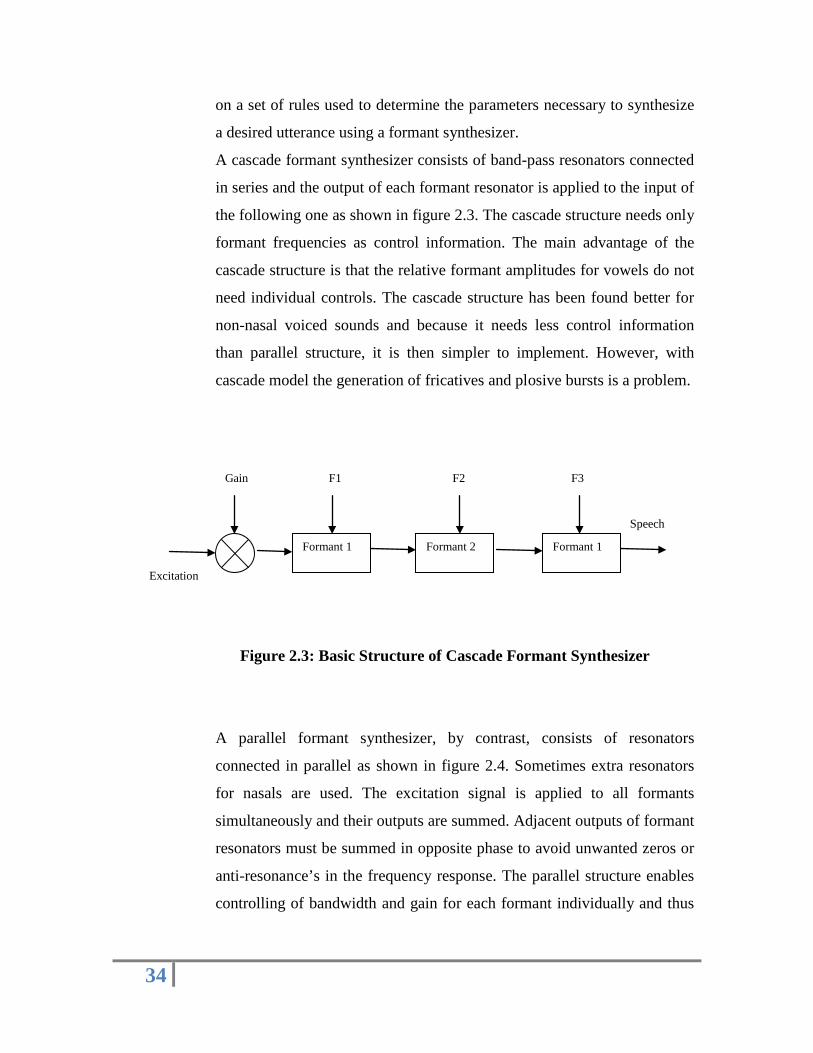
A cascade formant synthesizer consists of band-pass resonators connected
in series and the output of each formant resonator is applied to the input of
the following one as shown in figure 2.3. The cascade structure needs only
formant frequencies as control information. The main advantage of the
cascade structure is that the relative formant amplitudes for vowels do not
need individual controls. The cascade structure has been found better for
non-nasal voiced sounds and because it needs less control information
than parallel structure, it is then simpler to implement. However, with
cascade model the generation of fricatives and plosive bursts is a problem.
Figure 2.3: Basic Structure of Cascade Formant Synthesizer
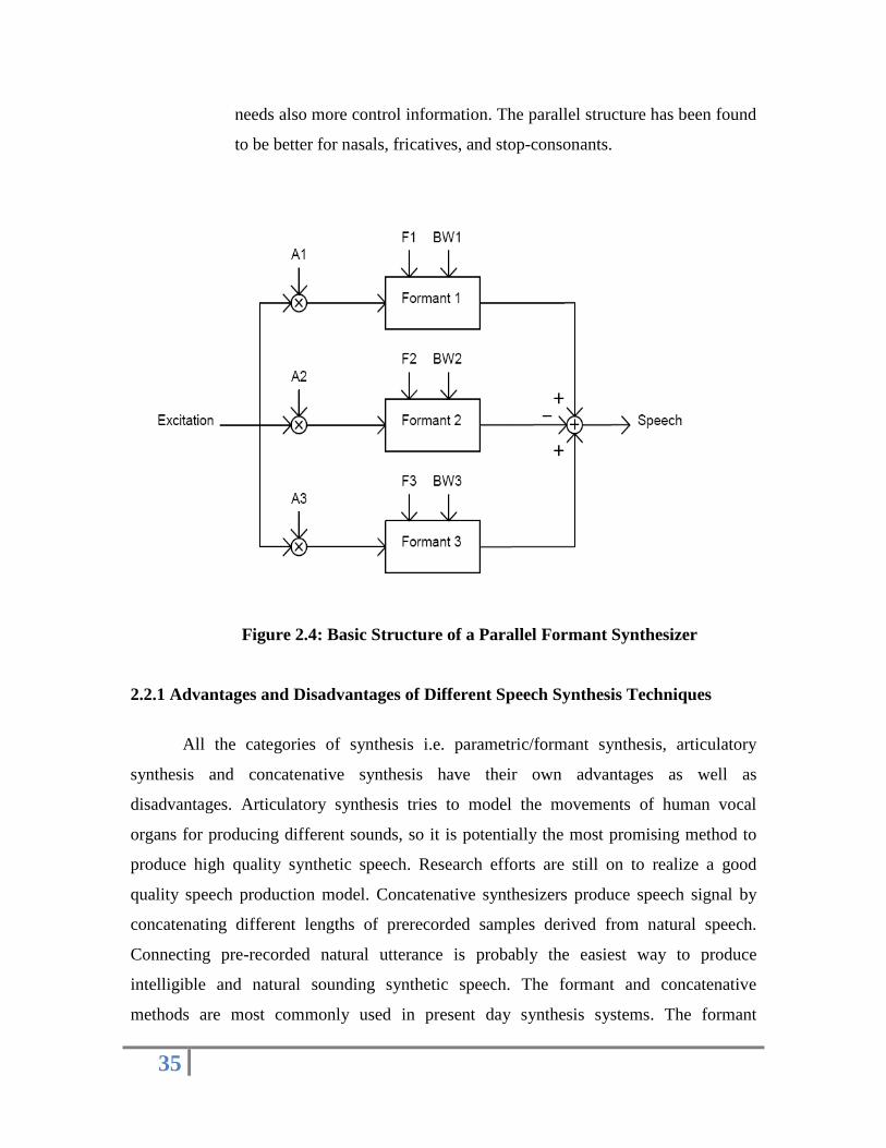
A parallel formant synthesizer, by contrast, consists of resonators
connected in parallel as shown in figure 2.4. Sometimes extra resonators
for nasals are used. The excitation signal is applied to all formants
simultaneously and their outputs are summed. Adjacent outputs of formant
resonators must be summed in opposite phase to avoid unwanted zeros or
anti-resonance’s in the frequency response. The parallel structure enables
controlling of bandwidth and gain for each formant individually and thus
Formant 1
Speech
Formant 2 Formant 1
F3 Gain
Excitation
F2 F1
35
needs also more control information. The parallel structure has been found
to be better for nasals, fricatives, and stop-consonants.
Figure 2.4: Basic Structure of a Parallel Formant Synthesizer
2.2.1 Advantages and Disadvantages of Different Speech Synthesis Techniques
All the categories of synthesis i.e. parametric/formant synthesis, articulatory
synthesis and concatenative synthesis have their own advantages as well as
disadvantages. Articulatory synthesis tries to model the movements of human vocal
organs for producing different sounds, so it is potentially the most promising method to
produce high quality synthetic speech. Research efforts are still on to realize a good
quality speech production model. Concatenative synthesizers produce speech signal by
concatenating different lengths of prerecorded samples derived from natural speech.
Connecting pre-recorded natural utterance is probably the easiest way to produce
intelligible and natural sounding synthetic speech. The formant and concatenative
methods are most commonly used in present day synthesis systems. The formant

36
synthesis was dominant for a long time, but today the concatenative method appears to be
becoming more popular. The articulatory method is still too complicated for high quality
implementations, but may arise as a potential method in the future.
The main advantage of the formant synthesis is that it requires very less memory,
which is a big advantage in using this technology in hand held applications/products. For
the concatenative synthesis, the advantage is very high quality (near natural) speech but
at a cost of much larger memory requirement. Formant synthesis is of course more
flexible and versatile.
Since we wish to explore ASIP design using parametric speech synthesis
(developed by D. H. Klatt) as the application, we now describe the Klatt’s synthesizer
model [4] [5] in some detail so that a conceptual reference frame can be built in the mind
for interpreting the results of further steps of application analysis and proposition of
datapath (execution unit) micro-architecture for the ASIP.
2.3 Klatt’s Speech Synthesizer
2.3.1 Introduction
In 1980, Dennis H. Klatt [4] proposed a more complex formant synthesizer which
incorporated both the cascade and parallel synthesizers with additional resonance’s and
anti-resonance’s for nasalized sounds, a sixth formant for high frequency noise, a bypass
path to give a flat transfer function, and a radiation characteristics. Dennis Klatt
introduced more sophisticated voicing source for his Klattalk system [5] [6]. The correct
and carefully selected excitation is important especially when good controlling of speech
characteristics is needed.
The public domain C language code of this synthesizer (released originally in
1980 using FORTRAN, 1988 version in C as KLSYN88 v1.2 and modified in 1994 as
klatt.3.04) forms the basis of many PC-based parametric speech synthesizers in different
languages [6]. It gives the user flexibility in terms of the choice of one of several
parameterized models of glottal source, the number and configuration of parameterized
resonators, sampling rate, inclusion or exclusion of effects like shimmer and diplophonic
double pulsing. The C code of the synthesizer like any other structured high-level
37
language program uses procedures and nested loops. The data I/O requirements of the
application are relatively modest in terms of the bandwidths required.
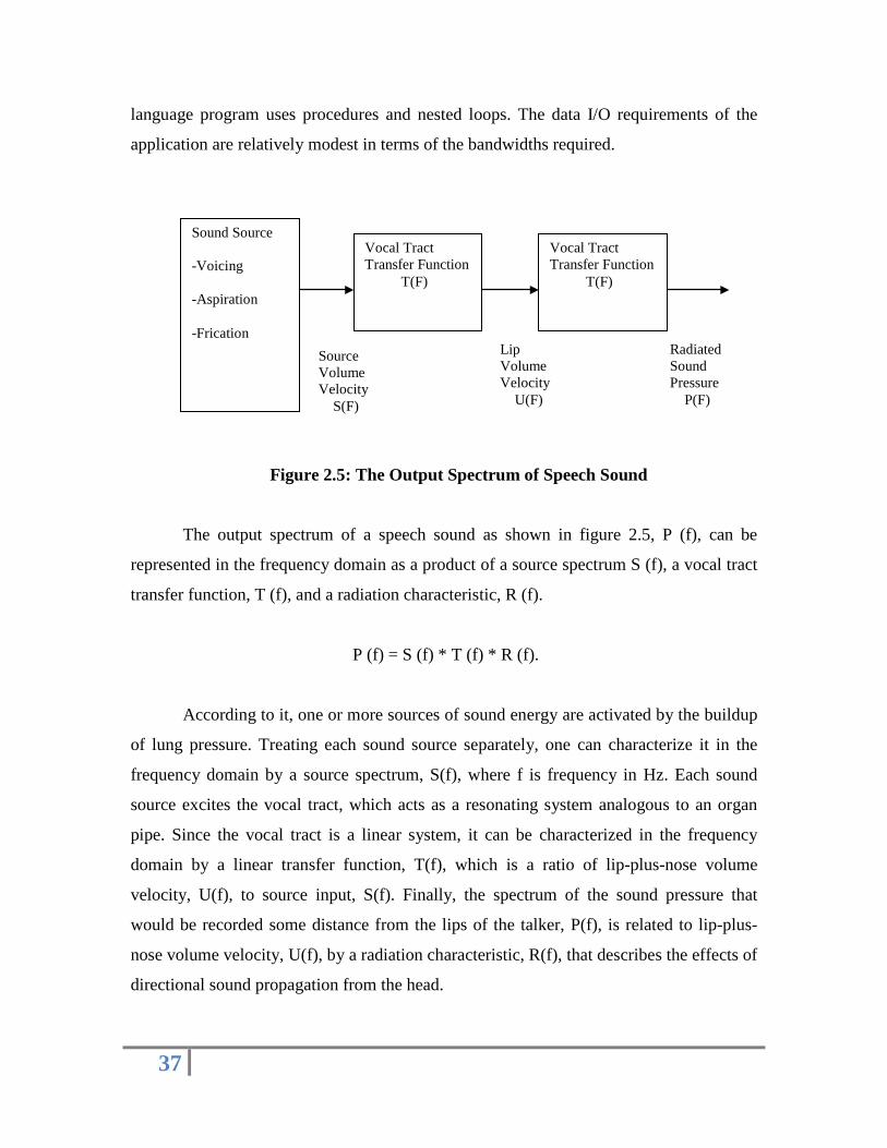
Figure 2.5: The Output Spectrum of Speech Sound
The output spectrum of a speech sound as shown in figure 2.5, P (f), can be
represented in the frequency domain as a product of a source spectrum S (f), a vocal tract
transfer function, T (f), and a radiation characteristic, R (f).
P (f) = S (f) * T (f) * R (f).
According to it, one or more sources of sound energy are activated by the buildup
of lung pressure. Treating each sound source separately, one can characterize it in the
frequency domain by a source spectrum, S(f), where f is frequency in Hz. Each sound
source excites the vocal tract, which acts as a resonating system analogous to an organ
pipe. Since the vocal tract is a linear system, it can be characterized in the frequency
domain by a linear transfer function, T(f), which is a ratio of lip-plus-nose volume
velocity, U(f), to source input, S(f). Finally, the spectrum of the sound pressure that
would be recorded some distance from the lips of the talker, P(f), is related to lip-plus-
nose volume velocity, U(f), by a radiation characteristic, R(f), that describes the effects of
directional sound propagation from the head.
Sound Source -Voicing -Aspiration -Frication
Vocal Tract Transfer Function T(F)
Source Volume Velocity S(F)
Lip Volume Velocity U(F)
Vocal Tract Transfer Function T(F)
Radiated Sound Pressure P(F)
38
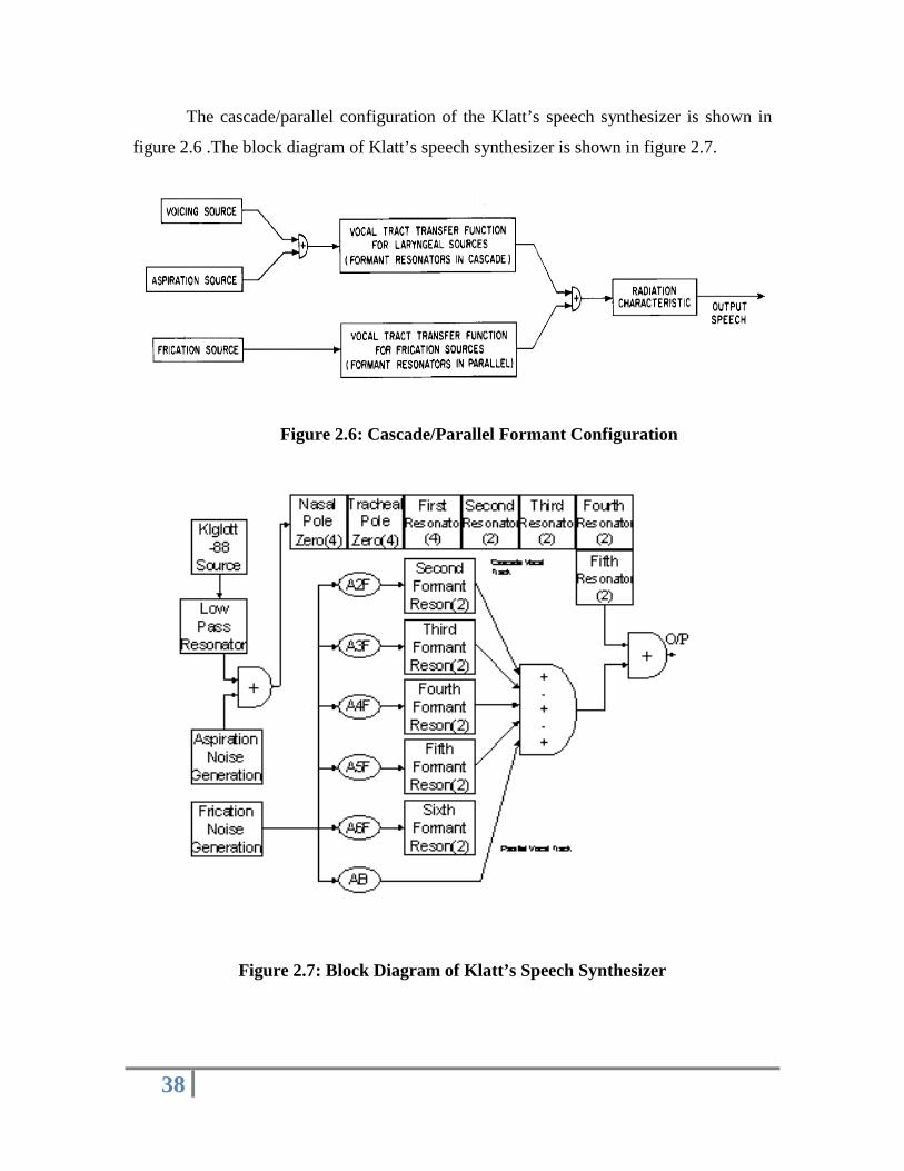
The cascade/parallel configuration of the Klatt’s speech synthesizer is shown in
figure 2.6 .The block diagram of Klatt’s speech synthesizer is shown in figure 2.7.
Figure 2.6: Cascade/Parallel Formant Configuration
Figure 2.7: Block Diagram of Klatt’s Speech Synthesizer

39
2.3.2 Control Parameters
Control parameter values are updated every 5 msec. This is frequent enough to
mimic even the most rapid of formant transitions and brief plosive bursts. There are 60
control parameters that determine the characteristics of the output. The name and range of
values for each parameter are given below:
F0: It is fundamental frequency of the voicing waveform. The
fundamental frequency changes over the course of a sentence and hence
the natural voicing is called “Quasi-periodic”.
Av: It is the peak amplitude of the glottal pulse.
Open Quotient (OQ): it is the ratio of open time to total period duration.
It determines the relative strength of the first harmonic.
Flutter (Fl): The KLYSYN88 voicing source model used FL control
parameter to simulate jitter. Instead of using a random process, we add to
the nominal F0 a quasi-random component, which is the sum of three
slowly varying sine waves.
∆F0 = F1/50 * F0/100 * [sin (2*12.7t) + sin (2*7.1t) + sin (2*4.7t)] Hz
∆F0 is added to the value of F0 before computing the period T0.
Diplophonia (DI): DI “diplophonic double pulsing” is the degree to
which the first of every pair of glottal pulse migrates towards the second
(i.e. delayed) and is attenuated in amplitude.
The delay is given by the following equation:
∆T0 = D1/100 * T0 * (1.0 – OQ/100)

40
A delayed pulse is attenuated in amplitude according to the equation:
AVlin = AVlin * (1.0 – DI/100)
Where, AVlin - linearised version of AV control parameter.
Spectral Tilt (TL): Tilt is realized by a critically damped digital
resonator. Bandwidth of the resonator is taken of a value, which is
specified by a conversion table. The frequency setting of a digital
resonator is kept in order to achieve critical damping i.e. Ftl = 0.375 Btl.
Normally, a digital filter has a unity gain at f = 0 Hz, but we desire a
behavior pattern such that the gain near F1 is nearly constant with changes
to spectral tilt. An approximation is used to make the gain at 300 Hz
nearly constant. The digital resonator gain constant (Atl) is adjusted
whenever TL > 10 accordingly to the formula:
Atl = Atl (1.0 + (TL – 10) * 2/1000)
Aspiration Amplitude (Asp): The amplitude of aspiration noise source,
AH is a scale factor specified in db and converted to a linear scale factor
(Ahlin) by table look up, that determines actual values of the aspiration
noise amplitude by simple amplitude multiplication:
Asp = ran * Ahlin
After scaling by the constant scale factor control parameter GH, the
aspiration noise has been calibrated such that the required audible sound is
generated. A value of zero turns off the aspiration source.
Frication Amplitude (Fric): The amplitude of the frication source, AF is
a scale factor specified in db and converted to linear scale factor by a look
up table. The actual value of frication noise is determined by a simple
multiplication:
Fric = ran * Aflin

41
After scaling by the constant gain factor (the control parameter, GF), the
frication has been calibrated such that the required audible sound is
generated. A value of zero turns off the frication source.
Amplitude modulation (AV): The output of the random number
generator is amplitude modulated of voicing whenever the amplitude of
voicing is greater than zero. Voiceless sound (AV= 0) is not amplitude
modulated because the vocal folds are spread and stiffened and do not
vibrate to modulate the airflow. The degree of amplitude modulation is
fixed to 50 % in the synthesizer, and the modulation envelope is a square
wave with a period equal to the fundamental period. This is accomplished
by multiplying the variable ran by 0.5 during the nominal closed phase of
the voicing period if AV is on i.e. AV > 0.
Formant Frequencies (F1, F2, F3, F4, F5, F6): These variables
determine the frequency in Hz up to six resonators in the cascade vocal
tract model and the frequencies of each of the five additional wideband
parallel formant resonators.
Formant Bandwidth (B1, B2, B3, B4, B5, B6): These variables
determine the bandwidth in Hz of the resonators in the cascade vocal tract
model.
Delta F1 (DF1) and Delta B1 (DB1) During Open Phase of Period: The
first formant bandwidth and frequency are not necessarily constant over
the duration of period. When the glottis is open, the first formant
frequency may increase by as much as 10 % and the glottal losses may
increase the first formant bandwidth significantly especially for the
vowels.
DF1 – the incremental increase if F1 during the open phase of the period
DB1 – the incremental increase in B1 during the open portion of each
42
period is used in order to allow pitch synchronous changes in F1 and B1
desired.
Nasal Pole and Zero Pair (FNP, FNZ, BNP, BNZ): The variable FNP –
frequency of nasal pole in contrast with the variable FNZ – frequency of
nasal zero can mimic this extra pole zero in nasal murmur spectra.
BNP and BNZ are corresponding bandwidths.
Tracheal Pole Zero Pair (FTP, FTZ, BTP, BTZ): The variable FTP –
frequency of tracheal pole in contrast with the variable FTZ – frequency of
the tracheal zero can mimic the primary spectral effects of tracheal
coupling in breathy vowels.
The variables BTP – bandwidth of tracheal pole and BTZ – bandwidth of
tracheal zero are set to default value 180 Hz.
Amplitude of Frication Exited Formants (A2F, A3F, A4F, A6F, AB):
The variables A2F through A6F amplitudes of the parallel formants
determines the spectral shape of a fricative or explosive burst. The bypass
path amplitude AB is used when the vocal tract response effects are
negligible because the cavity in front of the main fricative constriction is
too short.
Bandwidth of Frication Exited formants (B2F, B3F, B4F, B5F, B6F):
The variables are used in adjusting the parallel formant amplitudes in
order to match details in a natural frication spectrum.
2.3.3 Basic Building Block of Synthesizer
The basic building block of the synthesizer is a digital resonator as shown in
figure 2.8. Two parameters are used to specify the input-output characteristics of a
resonator, the resonant (formant) frequency F and the resonance bandwidth BW. Samples

43
of the output of a digital resonator, y(nT), are computed from the input sequence, x(nT),
by the equation:
y(nT) = Ax(nT) + By(nT - T) + Cy(nT - 2T)
Where y(nT-T) and y(nT- 2T) are the previous two sample values of the output
sequence y(nT), n is an integer and T is the sampling time.
The constants A, B, and C are related to the resonant frequency F and the
bandwidth BW of a resonator by the impulse invariant transformation and are computed
by the following equations:
C = -exp(-2*pi*BW*T),
B = 2*exp(-pi*BW*T) Cos(2*pi*F*T) and
A = 1-B-C
Figure 2.8: Block Diagram of a Digital Resonator
2.3.4 Sources of Sound
There are two kinds of sound sources that may be activated during speech
production [4]. One involves quasi-periodic vibrations of the vocal folds and is called
voicing source. The second kind of sound source involves the generation of turbulence
noise by the rapid flow of air past a narrow constriction. The resulting noise is called
44
aspiration if the constriction is located at the level of the vocal folds, as for example
during the production of the sound [h]. If the constriction is located above the larynx, as
for example during the production of sounds such as [s], the resulting noise is called
frication noise. The explosion of a plosive release also consists primarily of frication
noise [4].
When voicing and turbulence noise generation co-exist, as in a voiced fricative
such as [z] or a voiced [h], the noise is amplitude modulated periodically by the
vibrations of the vocal folds. In this type of voicing, the amplitude of higher frequency
harmonics of the voicing source spectrum is significantly reduced and the waveform
looks nearly sinusoidal. Therefore the synthesizer should be capable of generating at least
two types of voicing waveforms (normal voicing and quasi-sinusoidal voicing), two types
of frication waveforms (normal frication and amplitude-modulated frication), and two
types of aspiration (normal aspiration and amplitude-modulated aspiration). These are the
only kinds of sound sources required for Hindi language.
1) Voicing Source: The structure of the voicing source is shown at the top
left in figure 2.10. Variable control parameters are used to specify the
fundamental frequency of voicing (FO), the amplitude of normal voicing
(AV), and the amplitude of quasi-sinusoidal voicing (AVS). An impulse
train corresponding to normal voicing is generated whenever F0 is greater
than zero. AV, the amplitude of normal voicing in dB, determines the
amplitude of each impulse. AV ranges from about 60 dB in a strong vowel
to 0 dB when the voicing source is turned off. Fundamental frequency is
specified in Hz; a value of F0 = 100 would produce a 100-Hz impulse
train. The number of samples between impulses, TO is determined by
SR/F0 where SR is the sampling rate (in our case it is 12 KHz).
The amplitude control parameter AVS determines the amount of smoothed
voicing generated during voiced fricatives and the voiced aspirates.
Appropriate wave shapes for quasi-sinusoidal voicing is obtained by low
pass filtering of an impulse.

45
2) Turbulence Noise Source: A turbulent noise source is modeled in the
synthesizer by a pseudo-random number generator, a modulator, an
amplitude control AF. Signals produced by the random number generator
have a flat spectrum, but they have a uniform amplitude distribution
between limits determined by the value of the amplitude control parameter
AF. The spectrum of the frication source should be approximately flat.
The amplitude of the frication noise is determined by AF, which is given
in dB. A value of 60 will generate a strong frication noise, while a value of
zero effectively turns off the frication source.
Aspiration noise is essentially the same as frication noise, except that it is
generated in the larynx. In a strictly parallel vocal tract model, AF can be
used to generate both frication and aspiration noise. However, in the
cascade synthesizer configuration, aspiration noise is sent through the
cascade vocal tract model (since the cascade configuration is specially
designed to model vocal tract characteristics for laryngeal sound sources),
while fricatives require a parallel vocal tract configuration. Therefore
separate amplitude controls are needed for frication and aspiration in a
cascade/parallel configuration. The amplitude of aspiration noise sent to
the cascade vocal tract model is determined by AH, which is given in dB.
A value of 60 will generate strong aspiration, while a value of zero
effectively turns off the aspiration source.
2.3.5 Functions in Klatt’s C code
1) Get_host: This function gets variable parameters and also the constant
speaker defining parameters from the host. The combined total numbers of
parameters is 60 in one frame.
2) Pitch_sync_par: This function resets the selected parameters pitch-
synchronously.
3) Gen_noise: This function acts as the random number generator and is
used to generate noise. It computes the noise sample values by taking the
average of 12 random numbers.
46
4) Lpreson: This function computes the output of a resonator (second order
IIR digital filter). It computes the following equation:
y(nT) = Ax(nT) + By(nT - T) + Cy(nT - 2T)
5) Setrescoff: This function converts the formant frequencies and bandwidth
into resonator difference equation constants. It computes the resonator
coefficients A, B and C.
6) Natsource: This function models the voicing source (both normal and
quasi-sinusoidal voicing source).
The top-level structure of Klatt’s ‘C’ code strongly resembles the Klatt
synthesizer’s block diagram given in figure 2.7. A close look at the computations
performed by each functional block (as described earlier in the chapters) reveals that the
most frequent and dominant computations performed by the Klatt synthesizer are the
computations associated with resonators and filters. These essentially involve
multiplication and addition operations.
Besides, major and frequent computations are also performed for calculating the
resonator/filter coefficients from their corresponding parameters (e.g. formant frequency
and bandwidth). These computations involve computing trigonometric functions and
exponential functions, besides multiplication and addition. Random number generator
function is also frequently required to compute the noise sources. Some other operations
like division, decibel-to-linear are also required.
With this broad (qualitative) understanding of the computations involved in the
application, it is time to analyze the applications ‘C’ code to assess the frequencies of
each of the functions and operations to arrive at the picture of the computational load
which can guide the process of proposition of datapath (execution unit) micro-
architecture and instruction set definition over the micro-architecture in order to achieve
real-time execution of the application.


![VLSI ARCHITECTURE OF AN AREA EFFICIENT … Edge oriented Image scaling processor [16] ... VLSI Implementation of low-cost high quality image scaling processor [12] is proposed by for](https://static.fdocuments.in/doc/165x107/5b29d2027f8b9a2e1e8b4c98/vlsi-architecture-of-an-area-efficient-edge-oriented-image-scaling-processor-16.jpg)


