![3D Geological Modeling under Extremely Complex Geological ... · 3D geological modeling Ref. [4]. In 1994, 3D geological modeling technology was firstly put up by Simon W Houlding](https://static.fdocuments.in/doc/165x107/5e77a1369d577a7b9f489d8a/3d-geological-modeling-under-extremely-complex-geological-3d-geological-modeling.jpg)
Application of techniques of 3D geological and ...
21
Application of techniques of 3D geological and hydrodynamic modeling in designing of UGS in water- bearing structure with discontinuous faults (Shatrovskoye uplift). Shulkova L.A., Skosyrev А.V., Novoselova R.V. OJSC “VNIPIgazdobycha”, the city of Saratov, Russia OJSC “VNIPIgazdobycha”
Transcript of Application of techniques of 3D geological and ...

Application of techniques of 3D geological and hydrodynamic modeling in designing of UGS in water-
bearing structure with discontinuous faults (Shatrovskoye uplift).
Shulkova L.A., Skosyrev А.V., Novoselova R.V.
OJSC “VNIPIgazdobycha”, the city of Saratov, Russia
OJSC “VNIPIgazdobycha”

OJSC “VNIPIgazdobycha”
Ш а т р о в с к а я п л о щ а д ьС т р у к т у р н а я к а р т а п о к р о в л е
в и к у л о в с к о й с в и т ы
У с л о в н ы е о б о з н а ч е н и я :
А б с о л ю т н а я о т м е т к а к р о в л и в и к у л о в с к о й с в и т ыИ з о г и п с ы п о к р о в л е в и к у л о в с к о й с в и т ыП р е д п о л а г а е м ы е и з о г и п с ы п о к р о в л е в и к у л о в с к о й с в и т ы
У с т ь е с к в а ж и н ыН о м е р с к в а ж и н ы
- 5 2 0 . 3
1
- 2 5 0 2 5 0 5 0 0 7 5 0 1 0 0 00
Shatrovskaya area Contour map along the top
of vikulovskaya suite
Legend:
Well head
Well #
Elevation of vikulovskaya suite top
Isohypses along the top of vikulovskaya suite
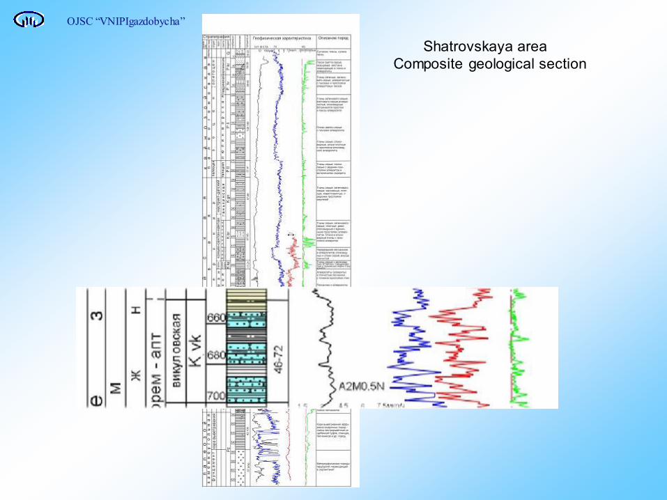
Shatrovskaya area
Composite geological section
OJSC “VNIPIgazdobycha”
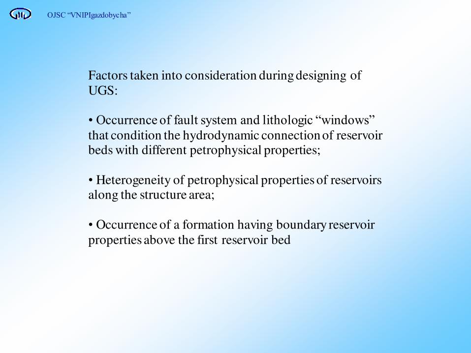
Factors taken into consideration during designing of
UGS: • Occurrence of fault system and lithologic “windows” that condition the hydrodynamic connection of reservoir beds with different petrophysical properties;
• Heterogeneity of petrophysical properties of reservoirs along the structure area;
• Occurrence of a formation having boundary reservoir
properties above the first reservoir bed
OJSC “VNIPIgazdobycha”
OJSC “VNIPIgazdobycha”

OJSC “VNIPIgazdobycha”
Well 3 Well 1 Well 2
Well 7 Well 1 Well 8
Geological profile in the line of wells 3,1,2
Geological profile in the line of wells 7,1,8

The results of modeling were used to solve the following problems:
• Determination of gas volume in UGS;
• Efficient location of operational wells within the structure, considering reservoir properties of the reservoir-beds and
providing for maximum use of a trap;
• Definition of optimum conditions for artificial gas storage formation, considering differentiated injection;
• Minimization of risk of gas spreading over the closing
isohypse;
• Organization of efficient observing system to follow
formation process of artificial gas storage;
• Determination of gas balance in UGS, considering gradual saturation of condensed differences.
OJSC “VNIPIgazdobycha”

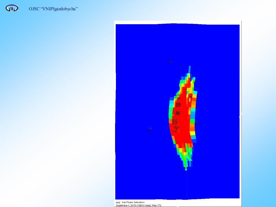
Shatrovskoye UGS
Gas saturation map
closing isohypse along the reservoir top
exploratory well
operational well
S gas
OJSC “VNIPIgazdobycha”

OJSC “VNIPIgazdobycha”
Shatrovskoye UGS
Gas saturation profile
Closing isohypse along the
reservoir top
S gas

OJSC “VNIPIgazdobycha”
Shatrovskoye UGS
Gas saturation profile
Closing isohypse along the reservoir top S gas
OJSC “VNIPIgazdobycha”

Different options including strings perforation were studied in order to define the best option for production mode of the
three-formation deposit:
• in the interval where only reservoirs of the upper reservoir bed are deposited,
• joint perforations of layers,
• differentiated injection and extraction according to the
formations.
OJSC “VNIPIgazdobycha”

Shatrovskoye UGS
Gas saturation map along formation I
(differentiated injection)
closing isohypse along the reservoir top
exploratory well
operational well
S gas
OJSC “VNIPIgazdobycha”

Gas saturation map along formation II
(differentiated injection)
closing isohypse along the reservoir top
exploratory well
operational well
S gas
OJSC “VNIPIgazdobycha”
Shatrovskoye UGS
OJSC “VNIPIgazdobycha”

Shatrovskoye UGS
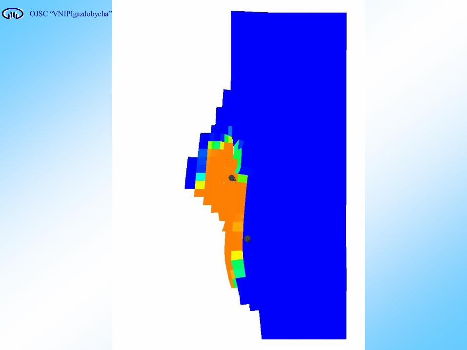
Arrangement of observation wells on formation III
exploratory well
observation well
S gas
closing isohypse along the reservoir top
fault line
OJSC “VNIPIgazdobycha”

Shatrovskoye UGS Diagrammatic geological profile of the upper part of the section
check water-bearing horizon
impermeable horizon
w3 w1 w2
OJSC “VNIPIgazdobycha”
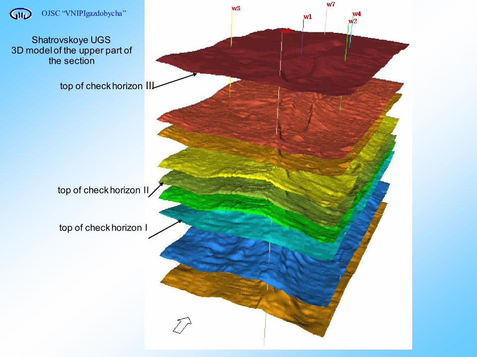
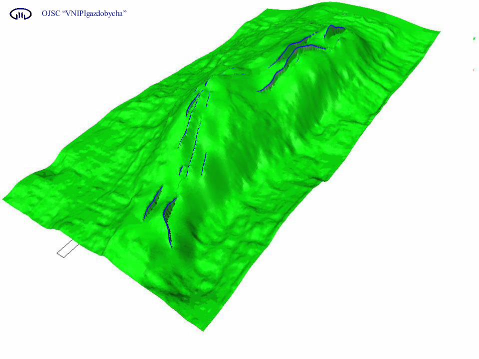
Shatrovskoye UGS 3D model of the upper part of
the section
top of check horizon II
top of check horizon III
top of check horizon I
OJSC “VNIPIgazdobycha”

Shatrovskoye UGS Contour map along the top of check water-bearing horizon
design check well
OJSC “VNIPIgazdobycha”

• Efficient location of production wells within the structure, considering reservoir properties of the reservoir-beds and providing for maximum use of a trap;
• Determination of optimum conditions for artificial gas storage formation, considering differentiated injection;
• Minimization of risk of gas spreading over the closing isohypse;
• Organization of efficient observing system to follow the artificial gas deposit formation;
• Determination of gas balance in UGS, considering gradual saturation of condensed differences (of siltstone formation).
OJSC “VNIPIgazdobycha”

Thanks for your attention.
OJSC “VNIPIgazdobycha”
Institute “VNIPIgazdobycha”, Saratov, Russia.
Rimma Novoselova