
GEOLOGICAL AND MORPHOLOGICAL INVESTIGATIONS OF THE UNDERGROUND CITIES OF CAPPADOCIA USING GIS
N° 250
3D MODELLING OF GEOLOGICAL STRUCTURES FOR UNDERGROUND CAVERNS : A NEW AND SIMPLE
METHODOLOGY
P. VASKOU (Géostock) J. MORRUZZI (Géostock)
6th ARMS (Asian Rock Mechanic Symposium) 23-27 October 2010 – Delhi-(India)
3D MODELLING OF GEOLOGICAL STRUCTURES FOR UNDERGROUND CAVERNS:
A NEW AND SIMPLE METHODOLOGY
P. Vaskou & J. Morruzzi
Géostock - Mined Caverns Department 92563 Rueil-Malmaison - France
SYNOPSIS The visualization of geological structures (rock contacts, fractured zones, faults, dykes, etc.) is essential for the analysis of rock masses before and during the excavation of large underground caverns. A relatively light methodology was developed for model construction using only a database and AutoCAD® or 3ds Max®. This simplicity allows having step by step models, from investigation to construction phase. The benefits, presented through case studies, are obvious for geological interpretations but above all for rock mechanics and civil engineering, due to the simplicity of visualization. 1 PRESENT STATE OF 3D GEOLOGICAL MODELLING Except on large and long-term projects for which the investment is possible, medium- or small-size projects generally do not invest on 3D geological modelling (3D being taken here in the sense of visualization or representation of geological features). Too often, geological input data stay, in the best cases, at a 2D level and in the great majority in paper reports. Such a situation is mainly due to the fact that 3D geological software programmes are rather complicated and generally expensive. At present, geological software programmes can be categorized into four types: - oil & gas software programmes, covering a wide range of activities, from geophysical survey to wireline logging; they are often restricted to oil & gas industry since rather expensive. They are more adapted to sedimentary rocks with sub-horizontal structural features than to hard rock environments with sub-vertical features (joints, dykes, etc.), - mining software programmes, nowadays extremely powerful and covering much more than the geological aspects; the market of mining software is mature and software programmes have been developed for precise goals; however, these big software programmes are difficult to handle, need a dedicated training and finally cannot be used by anyone. They are now easily run on standard PCs, - tool-box programmes, generally composed of several (even many) independent modules, sold separately; these software programmes are relatively easy to use and thus represent good tools for field and/or desktop geologists; 2D is common but 3D is less achievable; they can be run on PCs and even laptops, - imagery software programmes, used for earth sciences and medical sciences; they represent the uppermost visualization systems in 3D but need quite big computers and powerful graphic cards.
2 CONSTRAINTS IN 3D MODELLING OF GEOLOGICAL STRUCTURE Very often and especially during investigation and design phases, the use of a geological software programme remains too often a constraint instead of being a help for a project team. Reasons are multiple, and among others one can itemize the following ones: - using the software programme is uneasy (if not difficult) - software programmes are good to model geology but less efficient to represent complex
underground works, requiring frequent import from and export to AutoCAD® - too often, models can only be read using the modelling software itself which requires all users to
be connected or to have a licence of the software on their computer - 3D models are not accurate in term of image quality and rendering - the cost of geological software programmes (licence or lease) can be prohibitive for small
projects. From this situation and considering that AutoCAD® is almost systematically used to import construction drawings into geological software programmes, we have tried to do backwards and import geological data into AutoCAD®, the principal objective being to get the highest quality in term of visualization. 3 METHODOLOGY DEVELOPED FOR UNDERGROUND CAVERNS Underground caverns, excavated for storing all types of hydrocarbons (LPGs, crude oil, refined products such as diesel oil or naphtha, etc.), require from the site selection toward the design and construction phase the integration of various geological, hydrogeological and rock mechanical data. Before developing hydrogeological modelling (for assessing the water seepage rate for example) and rock mechanical modelling (for stability and reinforcement issues) a geological model is required. When working in homogeneous rock masses such as granite or gneiss or if caverns are located in one single geological formation, the 3D geological model is often simplified into a 3D structural model in which rock is not represented while only the main structural features are. In addition, the weathered layers (e.g. SW, MW, etc.) are also included to enrich the 3D structural model. This approach simplifies the creation of the 3D models and emphasizes on discontinuities, which are the crucial aspects regarding stability issues as well as hydrogeology. Last but not least, when only discontinuities are represented, visualization is greatly enhanced and non geologists easily appropriate the model to work with. The enormous improvements of AutoCAD® and in particular in 3D made the objective to model directly in this software possible. Tens years of geological modelling allowed testing, improving and a procedure which allows providing 3D models in structural geology of underground storages. The workflow is presented in Figure 1. In this frame, it was crucial to import all types of data into AutoCAD®, and in particular data from boreholes. This was made possible using very simple but efficient software, Drill&Log®, created by Austrian geologists. This software is a borehole database, which can be used basically for establishing 2D core descriptions can also directly create 3D files under AutoCAD® format (.dwg). In 3D, borehole parameters (RQD, rock type, Lugeon tests, weathering grade, BHTV, etc.) are presented using different colours, symbols or diameter, to characterize the variability. This being done, all the observations made on cores, results of laboratory samples, in situ tests, etc. are geo-referenced and can be manipulated in AutoCAD®. By selecting parameters (alone or associated), a geologist can build a model directly in 3D. All other parameters (topographic survey, MNT, refraction or reflexion seismic survey, ground surface measurements, GPS data, etc.) can be exported from the dedicated applications, most of then being now compatible with AutoCAD®.
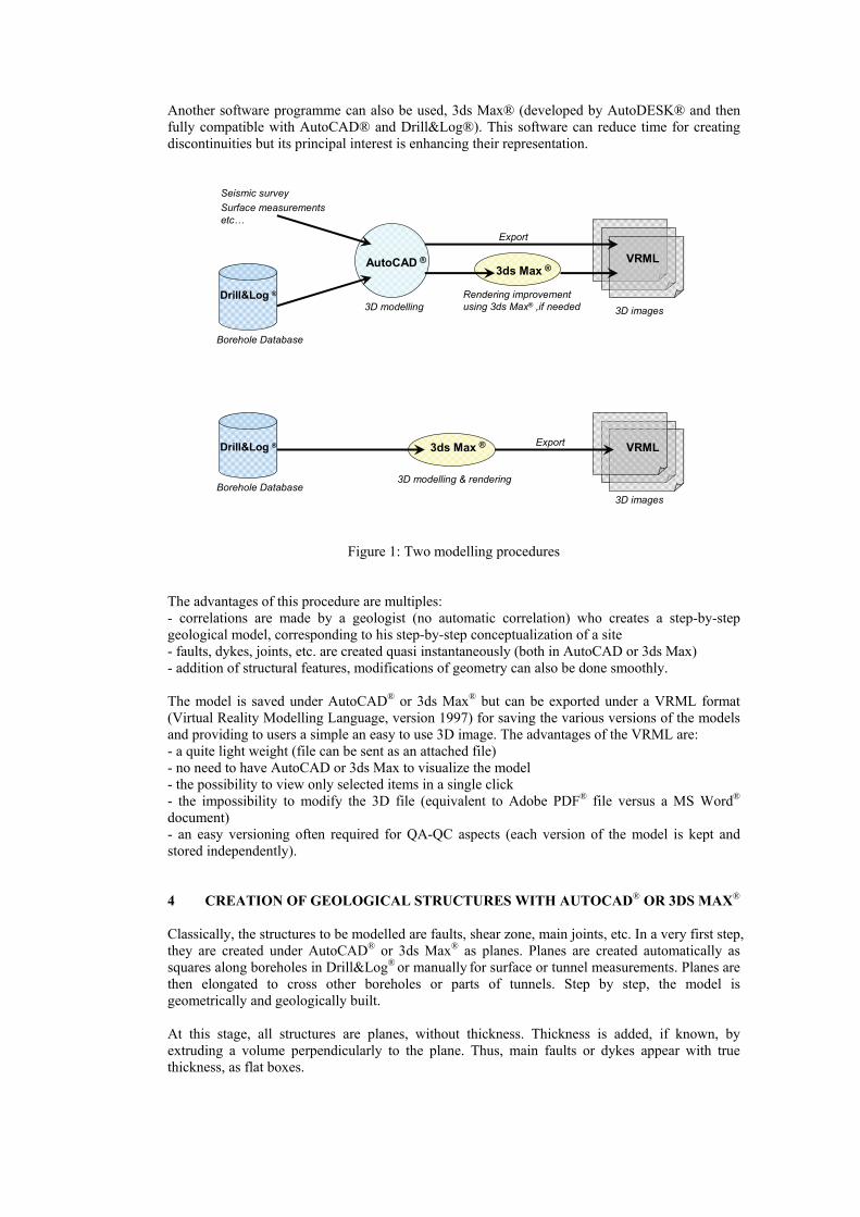
Another software programme can also be used, 3ds Max® (developed by AutoDESK® and then fully compatible with AutoCAD® and Drill&Log®). This software can reduce time for creating discontinuities but its principal interest is enhancing their representation.
Drill&Log ®
Borehole Database
Borehole Database
Seismic surveySurface measurementsetc…
AutoCAD ®
3D modelling
3ds Max ®
Rendering improvement using 3ds Max® ,if needed 3D images
3D modelling & rendering
3D images
VRML
Export
ExportDrill&Log ® 3ds Max ® VRML
Figure 1: Two modelling procedures
The advantages of this procedure are multiples: - correlations are made by a geologist (no automatic correlation) who creates a step-by-step geological model, corresponding to his step-by-step conceptualization of a site - faults, dykes, joints, etc. are created quasi instantaneously (both in AutoCAD or 3ds Max) - addition of structural features, modifications of geometry can also be done smoothly. The model is saved under AutoCAD® or 3ds Max® but can be exported under a VRML format (Virtual Reality Modelling Language, version 1997) for saving the various versions of the models and providing to users a simple an easy to use 3D image. The advantages of the VRML are: - a quite light weight (file can be sent as an attached file) - no need to have AutoCAD or 3ds Max to visualize the model - the possibility to view only selected items in a single click - the impossibility to modify the 3D file (equivalent to Adobe PDF® file versus a MS Word® document) - an easy versioning often required for QA-QC aspects (each version of the model is kept and stored independently). 4 CREATION OF GEOLOGICAL STRUCTURES WITH AUTOCAD® OR 3DS MAX® Classically, the structures to be modelled are faults, shear zone, main joints, etc. In a very first step, they are created under AutoCAD® or 3ds Max® as planes. Planes are created automatically as squares along boreholes in Drill&Log® or manually for surface or tunnel measurements. Planes are then elongated to cross other boreholes or parts of tunnels. Step by step, the model is geometrically and geologically built. At this stage, all structures are planes, without thickness. Thickness is added, if known, by extruding a volume perpendicularly to the plane. Thus, main faults or dykes appear with true thickness, as flat boxes.
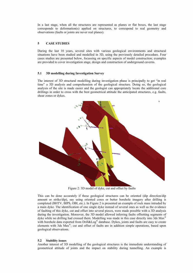
In a last stage, when all the structures are represented as planes or flat boxes, the last stage corresponds to deformation(s) applied on structures, to correspond to real geometry and observations (faults or joints are never real planes). 5 CASE STUDIES During the last 10 years, several sites with various geological environments and structural situations have been studied and modelled in 3D, using the previously detailed procedure. Four cases studies are presented below, focussing on specific aspects of model construction; examples are provided to cover investigation stage, design and construction of underground caverns. 5.1 3D modelling during Investigation Survey The interest of 3D structural modelling during investigation phase is principally to get “in real time” a 3D analysis and comprehension of the geological structure. Doing so, the geological analysis of the site is made easier and the geologist can appropriately locate the additional core drillings in order to cross with the best geometrical attitude the anticipated structures, e.g. faults, shear zones or dykes.
Figure 2: 3D model of dyke, cut and offset by faults
This can be done accurately if these geological structures can be oriented (dip direction/dip amount or strike/dip), say using oriented cores or better borehole imagery after drilling is completed (BHTV, BIPS, OBI, etc.). In Figure 2 is presented an example of rock mass intruded by a main dyke. The identification of one single dyke instead of several ones as well as the evidence of faulting of this dyke, cut and offset into several pieces, were made possible with a 3D analysis during the investigation. Moreover, the 3D model allowed inferring faults offsetting segments of dyke while no drilling had crossed them. Modelling was made in this case directly into 3ds Max® with borehole data exported from Drill&Log® database. Dykes, joints and faults are easy to create elements with 3ds Max®; cut and offset of faults are in addition simple operations, based upon geological observations. 5.2 Stability issues Another interest of 3D modelling of the geological structures is the immediate understanding of geometrical attitude of joints and the impact on stability during tunnelling. An example is
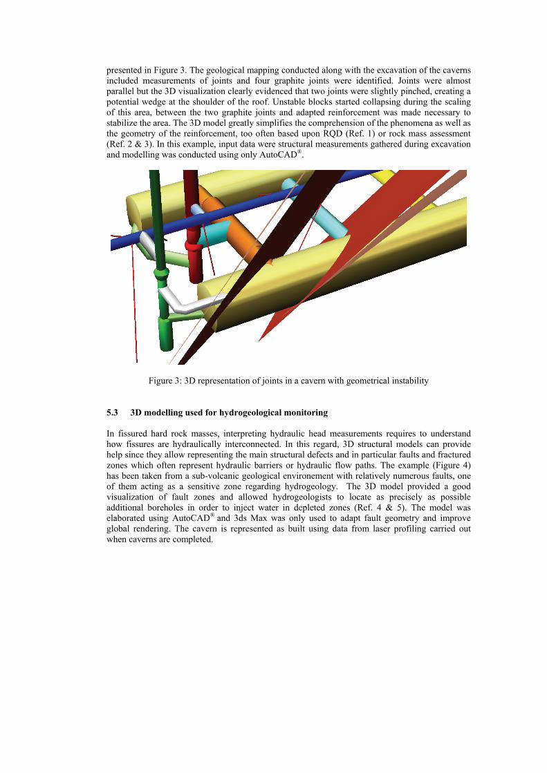
presented in Figure 3. The geological mapping conducted along with the excavation of the caverns included measurements of joints and four graphite joints were identified. Joints were almost parallel but the 3D visualization clearly evidenced that two joints were slightly pinched, creating a potential wedge at the shoulder of the roof. Unstable blocks started collapsing during the scaling of this area, between the two graphite joints and adapted reinforcement was made necessary to stabilize the area. The 3D model greatly simplifies the comprehension of the phenomena as well as the geometry of the reinforcement, too often based upon RQD (Ref. 1) or rock mass assessment (Ref. 2 & 3). In this example, input data were structural measurements gathered during excavation and modelling was conducted using only AutoCAD®.
Figure 3: 3D representation of joints in a cavern with geometrical instability 5.3 3D modelling used for hydrogeological monitoring In fissured hard rock masses, interpreting hydraulic head measurements requires to understand how fissures are hydraulically interconnected. In this regard, 3D structural models can provide help since they allow representing the main structural defects and in particular faults and fractured zones which often represent hydraulic barriers or hydraulic flow paths. The example (Figure 4) has been taken from a sub-volcanic geological environement with relatively numerous faults, one of them acting as a sensitive zone regarding hydrogeology. The 3D model provided a good visualization of fault zones and allowed hydrogeologists to locate as precisely as possible additional boreholes in order to inject water in depleted zones (Ref. 4 & 5). The model was elaborated using AutoCAD® and 3ds Max was only used to adapt fault geometry and improve global rendering. The cavern is represented as built using data from laser profiling carried out when caverns are completed.
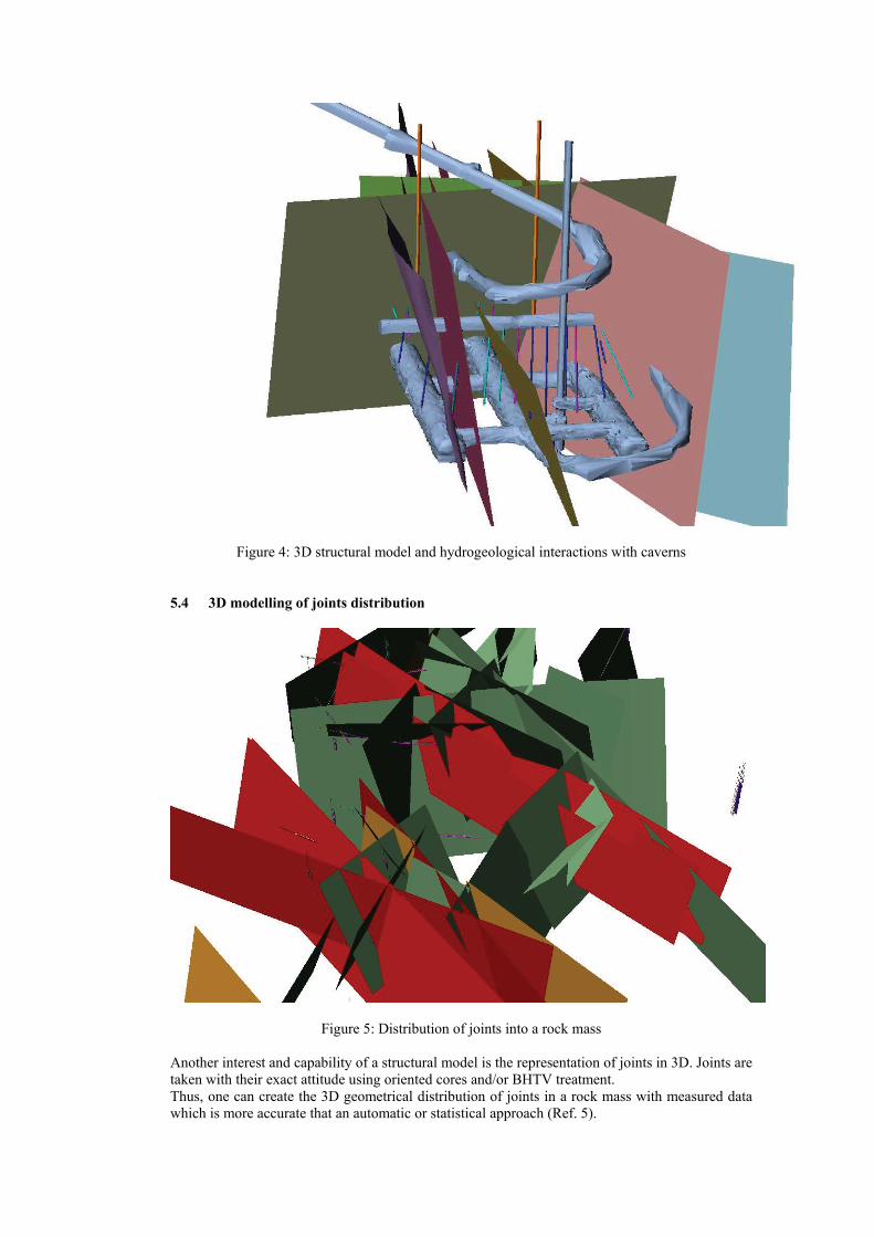
Figure 4: 3D structural model and hydrogeological interactions with caverns 5.4 3D modelling of joints distribution
Figure 5: Distribution of joints into a rock mass Another interest and capability of a structural model is the representation of joints in 3D. Joints are taken with their exact attitude using oriented cores and/or BHTV treatment. Thus, one can create the 3D geometrical distribution of joints in a rock mass with measured data which is more accurate that an automatic or statistical approach (Ref. 5).
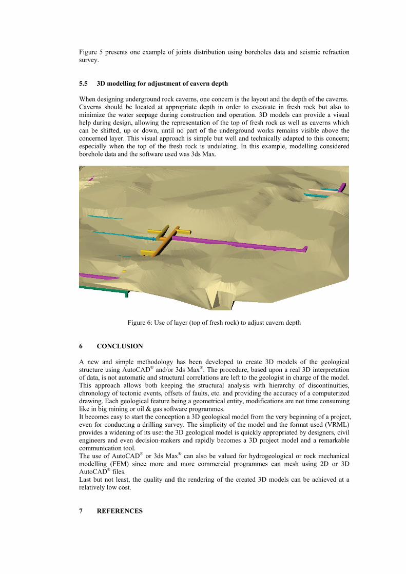
Figure 5 presents one example of joints distribution using boreholes data and seismic refraction survey. 5.5 3D modelling for adjustment of cavern depth When designing underground rock caverns, one concern is the layout and the depth of the caverns. Caverns should be located at appropriate depth in order to excavate in fresh rock but also to minimize the water seepage during construction and operation. 3D models can provide a visual help during design, allowing the representation of the top of fresh rock as well as caverns which can be shifted, up or down, until no part of the underground works remains visible above the concerned layer. This visual approach is simple but well and technically adapted to this concern; especially when the top of the fresh rock is undulating. In this example, modelling considered borehole data and the software used was 3ds Max.
Figure 6: Use of layer (top of fresh rock) to adjust cavern depth 6 CONCLUSION A new and simple methodology has been developed to create 3D models of the geological structure using AutoCAD® and/or 3ds Max®. The procedure, based upon a real 3D interpretation of data, is not automatic and structural correlations are left to the geologist in charge of the model. This approach allows both keeping the structural analysis with hierarchy of discontinuities, chronology of tectonic events, offsets of faults, etc. and providing the accuracy of a computerized drawing. Each geological feature being a geometrical entity, modifications are not time consuming like in big mining or oil & gas software programmes. It becomes easy to start the conception a 3D geological model from the very beginning of a project, even for conducting a drilling survey. The simplicity of the model and the format used (VRML) provides a widening of its use: the 3D geological model is quickly appropriated by designers, civil engineers and even decision-makers and rapidly becomes a 3D project model and a remarkable communication tool. The use of AutoCAD® or 3ds Max® can also be valued for hydrogeological or rock mechanical modelling (FEM) since more and more commercial programmes can mesh using 2D or 3D AutoCAD® files. Last but not least, the quality and the rendering of the created 3D models can be achieved at a relatively low cost. 7 REFERENCES
(1) Deere D. U. – 1963 - Technical description of rock cores for engineering purposes. Rock. Mech. Engng. Geol. 1, 16-22.
(2) Barton N. R., Lien R. & Lunde J. (1974) Engineering classification of rock masses for the
design of tunnel support. Rock mech, Vol. 6, N° 4, 189-239.
(3) Bieniawsky Z. T. (1973) Engineering classification of jointed rock masses. Trans. South Afr. Inst. Civil Engineers, Vol. 15, pp. 335-344.
(4) Goldschneider A., Morruzzi J., Bodin JL., Amantini E. & Vaskou P. – 2009 - Coupled geological and hydrogeological models in fractured systems: understanding interactions between underground storages and their rockmass, Proc. Symposium IAHS & IAH, Hyderabad, IAHS Publication n°331, 449-458.
(5) Giafferi JL. et al. (2003) Characterisation of rock masses useful for the design and the
construction of underground structures. AFTES guidelines; Tunnels et Ouvrages souterrains, N° 177, 2-49.
Philippe VASKOU graduated in 1978 in Geology and obtained a Ph.D. in 1981 in France. From 1981 to 1997 he worked as an engineering geologist with EDF (French Electrical Board) mainly for hydropower plants. He joined Géostock in 1997 and till now, he is at the head of geological team in the mined cavern department. His rich and worldwide experience gave him the opportunity to develop strong relationships with rock mechanical and civil engineers. From this, he understood the need to popularize structural geology and developed “home-made” 3D models. Justine Morruzzi graduated in 2008 as an engineering geologist in Nancy, France. From this time, she has been working for Géostock; being in charge of structural interpretations and 3D geological modelling of underground mined caverns.


![AssessmentoftheExcavationDamagedZonesintheSurrounding ... · 2020. 7. 4. · velocitytestinghasbeenwidelyusedfortheassessmentof EDZs in underground caverns and dam foundations [38]](https://static.fdocuments.in/doc/165x107/60c1e8ccffaaf0368c4f9cba/assessmentoftheexcavationdamagedzonesinthesurrounding-2020-7-4-velocitytestinghasbeenwidelyusedfortheassessmentof.jpg)


