Application of biogas to supply ... - combustion-engines.eu influence of, among other things, the...
7
Article citation info: BIENIEK, A., MAMALA, J., GRABA, M. et al. Application of biogas to supply the high compression ratio engine. Combustion Engines. 2019, 179(4), 40-46. DOI: 10.19206/CE-2019-406 40 COMBUSTION ENGINES, 2019, 179(4) Andrzej BIENIEK CE-2019-406 Jarosław MAMALA Mariusz GRABA Krzysztof PRAŻNOWSKI Michał ŚMIEJA Dariusz WERESZCZYŃSKI Application of biogas to supply the high compression ratio engine The study concerns the use of biogas as a fuel for supplying a modified self-ignition engine. As a result of the modifications made, the compression ratio was reduced and the engine was equipped with an ignition system and an electronically activated engine throttle. The changes have made it possible to burn biogas in a high compression ratio engine. The paper presents the results of research conducted on a low power cogeneration system with engine that drives an electrical machine cooperating with a 380/400 V network. The analysis includes, among other things, the possibility of producing electricity using biogas. The paper presents the influence of regulatory param- eters such as the volume and composition of the supplied gas mixture and the degree of throttle opening on the obtained engine opera- tion indicators and the driven electric machine. The tests were carried out in relation to the obtained ecological indicators depending on the concentration in the exhaust of such substances as: HC, CO, NO x . Key words: biogas, high compression ratio engine, emission, low power cogeneration system 1. Introduction Combustion engines could be powered with different fuels. One of important fuel groups consists of gaseous fuels. There are fuels as generator gas with very low calo- rific value [5] from hydrogen [6] and fermentation gas (biogas) up to methane CH 4 . The properties of selected gaseous fuels are listed in Table 1. It should be noted that methane, which is the main component of biogas and natu- ral gas is characterized by a high octane number. That al- lows it to supply engines with a high compression ratio and combust without knocking. Biogas can be made from agri- cultural waste, which makes it possible to use the energy contained in it. Table 1. Properties characteristic for choosen gasenous fuels [8, 13] Gasenous fuel Density, kg·Nm –3 Calorific value, MJ·Nm –3 Calorific value of stechiom. mixture, MJ·m –3 λ index for the lower flammable limit MON Methane 0.714 35.8 3.18 2.00 110 Propane 1.963 91 3.42 2.06 95 Butane 2.588 118 3.44 1.70 92 Natural gas 0.695 34.7 3.4 2.10 100–110 Coal gas 0.468 13 3.35 – 95 Generator gas 1.015 5.65 2.6 4.35 105 Illumina- tion gas 0.614 17 3.25 2.50 90 Biogas 54% CH4 1.276 19.3 2.71 2.16 110 Propane – butane (50%/50%) 2.080 96.5 3.35 1.91 95 Hydrogen 0.089 10.8 3.03 10 130 There are many opportunities to use energy from bio- gas. Very often, in the case of stationary applications, the conversion of energy contained in the biogas fuel is used for generating electricity. However, in order to improve the efficiency of the entire system, ie. to avoid energy losses, CHP cogeneration systems are built to simultaneously gen- erate electricity and heat. Further improvement of energy indicators is possible with the use of trigeneration systems in which, in addition to electricity and heat production, biogas energy can be used during the sorption process (ad- sorption and absorption of cold). Among the various me- thods of using biogas energy, one can distinguish the use of gas combustion in a piston combustion engine. For this purpose, compression-ignition or spark-ignition engines are used. In the case of an engine fueled with diesel fuel, some modifications are required. It can be use dual fuel supply system (diesel and biogas) or only biogas. In the second case, it is often necessary to change the some construction properties of the engine in order to lower the compression ratio and adding equipment with an ignition system similar to those used in engines operating in the Otto cycle [4, 14]. In many cases, particularly relatively simple construction engines, the introduction of modifications does not lead to higher technical and economic expenses [14]. Fig. 1. Energy balance of an internal combustion engine operating in a cogeneration system [7]
Transcript of Application of biogas to supply ... - combustion-engines.eu influence of, among other things, the...

Article citation info:
BIENIEK, A., MAMALA, J., GRABA, M. et al. Application of biogas to supply the high compression ratio engine. Combustion
Engines. 2019, 179(4), 40-46. DOI: 10.19206/CE-2019-406
40 COMBUSTION ENGINES, 2019, 179(4)
Andrzej BIENIEK CE-2019-406
Jarosław MAMALA
Mariusz GRABA Krzysztof PRAŻNOWSKI
Michał ŚMIEJA
Dariusz WERESZCZYŃSKI
Application of biogas to supply the high compression ratio engine
The study concerns the use of biogas as a fuel for supplying a modified self-ignition engine. As a result of the modifications made, the
compression ratio was reduced and the engine was equipped with an ignition system and an electronically activated engine throttle. The
changes have made it possible to burn biogas in a high compression ratio engine. The paper presents the results of research conducted
on a low power cogeneration system with engine that drives an electrical machine cooperating with a 380/400 V network. The analysis
includes, among other things, the possibility of producing electricity using biogas. The paper presents the influence of regulatory param-
eters such as the volume and composition of the supplied gas mixture and the degree of throttle opening on the obtained engine opera-
tion indicators and the driven electric machine. The tests were carried out in relation to the obtained ecological indicators depending on
the concentration in the exhaust of such substances as: HC, CO, NOx.
Key words: biogas, high compression ratio engine, emission, low power cogeneration system
1. Introduction
Combustion engines could be powered with different
fuels. One of important fuel groups consists of gaseous
fuels. There are fuels as generator gas with very low calo-
rific value [5] from hydrogen [6] and fermentation gas
(biogas) up to methane CH4. The properties of selected
gaseous fuels are listed in Table 1. It should be noted that
methane, which is the main component of biogas and natu-
ral gas is characterized by a high octane number. That al-
lows it to supply engines with a high compression ratio and
combust without knocking. Biogas can be made from agri-
cultural waste, which makes it possible to use the energy
contained in it.
Table 1. Properties characteristic for choosen gasenous fuels [8, 13]
Gasenous fuel
Density, kg·Nm–3
Calorific value,
MJ·Nm–3
Calorific value of stechiom.
mixture, MJ·m–3
λ index for the lower
flammable limit
MON
Methane 0.714 35.8 3.18 2.00 110
Propane 1.963 91 3.42 2.06 95
Butane 2.588 118 3.44 1.70 92
Natural gas 0.695 34.7 3.4 2.10 100–110
Coal gas 0.468 13 3.35 – 95
Generator
gas
1.015 5.65 2.6 4.35 105
Illumina-
tion gas
0.614 17 3.25 2.50 90
Biogas 54% CH4
1.276 19.3 2.71 2.16 110
Propane –
butane (50%/50%)
2.080 96.5 3.35 1.91 95
Hydrogen 0.089 10.8 3.03 10 130
There are many opportunities to use energy from bio-
gas. Very often, in the case of stationary applications, the
conversion of energy contained in the biogas fuel is used
for generating electricity. However, in order to improve the
efficiency of the entire system, ie. to avoid energy losses,
CHP cogeneration systems are built to simultaneously gen-
erate electricity and heat. Further improvement of energy
indicators is possible with the use of trigeneration systems
in which, in addition to electricity and heat production,
biogas energy can be used during the sorption process (ad-
sorption and absorption of cold). Among the various me-
thods of using biogas energy, one can distinguish the use of
gas combustion in a piston combustion engine. For this
purpose, compression-ignition or spark-ignition engines are
used. In the case of an engine fueled with diesel fuel, some
modifications are required. It can be use dual fuel supply
system (diesel and biogas) or only biogas. In the second
case, it is often necessary to change the some construction
properties of the engine in order to lower the compression
ratio and adding equipment with an ignition system similar
to those used in engines operating in the Otto cycle [4, 14].
In many cases, particularly relatively simple construction
engines, the introduction of modifications does not lead to
higher technical and economic expenses [14].
Fig. 1. Energy balance of an internal combustion engine operating in
a cogeneration system [7]

Application of biogas to supply the high compression ratio engine
COMBUSTION ENGINES, 2019, 179(4) 41
Therefore, it is possible to adapt existing engine con-
structions for biogas power supply with relatively small
modifications. In addition, the use of an internal combus-
tion engine in a cogeneration system allows to achieve
a high overall efficiency of up to 90% [7, 19]. Efficiency
with the inclusion only electrical energy generation very
rarely exceeds 40% – Fig. 1.
Other methods based on the use of, for example, Ran-
kine, Stirling engine, micro-turbines or fuel cells are char-
acterized by lower overall efficiency while working in a
CHP.
2. Biogas and combustion engine operating indexes The combustion of fuel in the engine is associated with
the emission of harmful substances. Particularly in the
diesel engine, it is important to reduce the emission of solid
particles PM, but also the remaining other harmful exhaust
components. In addition to the use of a environmental
friendly design, the use of an appropriate fuel dosing sys-
tem, and the aftertreatment method's, the type of fuel used
and its detailed composition are important. Reduction of
emissions is possible, for example, thanks to the use of
catalytic fuel additives, which makes it possible to reduce
PM emissions by up to over 60 percent [1]. However, the
best results can be achieved using gas fuels, including those
whose main component is methane.
Thanks to biogas supply, PM particulate emissions can
be significantly reduce by up to 99%, carbon dioxide by
25%, and nitrogen oxides by up to 95%. At the same time,
it is possible to achieve a reduction in fuel costs [20].
Both economic and ecological engine operating indexes
depend significantly on the composition of biogas. Due to
the fact that biogas can be produced using various technol-
ogies, as well as using different substrates, its composition
and properties may differ significantly [2, 16]. Table 2 and
3 show the composition of biogas obtained using its various
production technologies and the use of diverse substrates.
Table 2. The composition of biogas depending on the method of its pro-
duction [2]
Komponent Agricultural
biogas
Biogas from
energy crops Landfill biogas
CH4, % 45–75 57–62 37–67
CO2, % 25–55 33–38 24–40
O2, % 0.01–2.1 0–0.5 1–5
N2 ,% 0.01–5.0 3.4–8.1 20–25
H2S, ppm 10–30000 24–8000 15–400
Table 3. Substrates for the production of agricultural biogas and their
composition [16]
Substrat N2, % NH4, % P, % CH4, %
Maize silage 1.1–2 0.15–0.3 0.2–0.3 50–55
Grass silage 3.5–6.9 6.9–19.8 0.4–0.8 54–55
Rye silage 4.0 0.57 0.71 ca. 55
Pig slurry 6–18 3–17 0.2–1.0 60–70
Cattle slury 2.6–6.7 1–4 0.5–3.3 60
One of the most important issues is the percentage share
of CH4 in the volume of biogas, which directly translates
into such properties as the fuel calorific value. A change in
the calorific value results in a change of the engine opera-
tion indicators, such as its power and torque. Due to the
percentage volume of methane, the calorific value of biogas
can vary within very wide limits of 15–27 MJ·Nm–3
[22].
Not without significance is the participation of other sub-
stances, including NH4, which may have a negative effect
on the engine components causing corrosion.
Research and analysis carried out by many researchers
prove the desirability of further work related to the search
for solutions that enable the use of energy contained in
biogas during combustion in an internal combustion engine
[10–12, 17]. Some researchers are focusing on dual-fuel
solutions that do not require modifications to the CI engine
design (including reduction of compression ratio, adding of
the ignition system) [9, 17, 21, 23, 24]. As the results of the
tests show, the method of controlling the dual fuel engine
power is very important, taking into account the engine's
operating status. The conducted research also shows the
influence of, among other things, the degree of compression
on the overall efficiency of the engine and its ecological
properties [18].
Some research shows that the dual fuel supply system
causes a decrease in the overall engine efficiency. Com-
pared to the supply of only diesel fuel it decreases on aver-
age by approximately 17% (at full load as drop from 29%
to 24%). At medium engine loads, the efficiency of the
biogas supplied engine is approx. 20% in the case of un-
changed compression ratio compared to the diesel supply.
The higher compression ratio has a very favorable effect on
emissions, resulting in a decrease of CO concentration by
approx. 30%, HC by approx. 60%, but at the same time an
increase in NOx emissions by approx. 20% [18]. Also tests
carried out for biogas supply show maximum values of the
overall efficiency of the engine of 23.3% for a load of ap-
prox. 54%. This efficiency is slightly higher than with CNG
22,3%. In turn, with supply methane enriched biogas raises
the maximum efficiency value to 26.2% [3]. Similar maxi-
mum values of overall engine efficiency were obtained in
[15], slightly exceeding 22%.
Due to the required regulations regarding the use of re-
newable fuels, including Directive 2001/77/EC of the Eu-
ropean Parliament and of the Council of Europe on "sup-
porting the production of electricity from renewable sources
on the internal market", they increase the share of energy
from these sources. An additional decrease in the popularity
of first generation bio-fuels (including agricultural crops)
for the pressure to increase the second generation of renew-
able fuels (ie fuels created from products that cannot be
used for human or animal food, i.e. most often different
types of waste) shows that biogas can be seen as the fuel of
the future.
As it results from official statistics presented by gov-
ernment institutions, the share of renewable energy sources
in its overall production is still too small, and in particular it
concerns the use of biogas in this agricultural biogas [25].
3. Research methodology
3.1. Test bench
In order to estimate the obtained ecological and eco-
nomic indicators of the biogas-fueled research engine,
a cycle of stationary tests was carried out on a test stand.
Application of biogas to supply the high compression ratio engine
42 COMBUSTION ENGINES, 2019, 179(4)
That consisting of an internal combustion engine prepared
for operation in a cogeneration system that drives a three-
phase low power electric machine connected to a 380/400 V
network (Fig. 2). In this research program the possibility of
heat recovery in the cogeneration system was not taken into
account, but only the generation of electricity.
Fig. 2. Test bench
The test engine was modified (Table 4). It was equipped
with an ignition system with the possibility of adjusting the
ignition advance angle and an electronic control throttle
mounted in the intake system and additionally with a high
resolution speed sensor.
Table 4. Basic construction parameters of the engine
Parameter Value Unit
Mark S-312B –
Displacement 1.960 dm3
Maximum power (Diesel) 20.6 kW
Engine speed for maximum power 2200 rpm
Maximum torque (Diesel) 100 Nm
Engine speed for maximum torque 1600–1800 rpm
Diameter/ stroke of the piston 102/120 mm
Compression ratio (original) 17.0 –
Compression ratio after modifications 15.0 –
Table 5. Basic construction parameters of the electric machine.
Parameter Value Unit
Mark Indukta 2SIEL160M4 –
Power supply voltage 400 V
Rated power 11 kW
Rotational speed 1520 rpm
Current for rated power 21 A
Maximum torque 71.95 Nm
Efficiency with a load 2/4 88.2 %
Efficiency with a load 3/4 89.3 %
Efficiency with a load 4/4 89 %
Number of poles 4 –
Mass 105 kg
Inertia 0.061 kg·m2
One of the important goals of modification was to ob-
tain a lower compression ratio compared to the factory
configuration of the S-312B engine, for which the compres-
sion ratio is εf = 17.0. As a result of increasing of the com-
bustion chamber volume (realized by reducing the piston
height), the compression ratio was reduced to ε = 15.0.
A Indukta electric machine with the designation
2SIEL160M4 was connected to the crankshaft of the modi-
fied engine. Its basic technical parameters are shown in
Table 5.
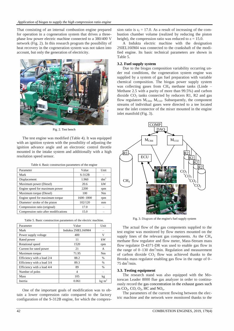
3.2. Fuel supply system
Due to the biogas composition variability occurring un-
der real conditions, the cogeneration system engine was
supplied by a system of gas fuel preparation with variable
chemical composition. The biogas power supply system
was collecting gases from CH4 methane tanks (Linde –
Methane 2.5 with a purity of more than 99.5%) and carbon
dioxide CO2 tanks connected by reducers R1, R2 and gas
flow regulators MCH4, MCO2. Subsequently, the component
streams of individual gases were directed to a tee located
near the inlet connector of the mixer mounted in the engine
inlet manifold (Fig. 3).
Fig. 3. Diagram of the engine's fuel supply system
The actual flow of the gas components supplied to the
test engine was monitored by flow meters mounted on the
supply lines of the relevant gas components. As the CH4
methane flow regulator and flow meter, Mass-Stream mass
flow regulator D-4371-DR was used to enable gas flow in
the range of 0–130 dm3/min. Regulation and measurement
of carbon dioxide CO2 flow was achieved thanks to the
Bronks mass regulator enabling gas flow in the range of 0–
75 dm3/min.
3.3. Testing equipment
The research stand was also equipped with the Mo-
torscan Leader 8000 flue gas analyzer in order to continu-
ously record the gas concentration in the exhaust gases such
as CO2, CO, O2, HC and NOx.
The parameters of the current flowing between the elec-
tric machine and the network were monitored thanks to the
MCH4 MCO2
R2
R2
R2
R2
R1
CH4
ECU
COMP
DAQ
CO2
CO2
CO2
CO2

Application of biogas to supply the high compression ratio engine
COMBUSTION ENGINES, 2019, 179(4) 43
use of LEM type circuits. In turn, the amount of electricity
produced is added up using the Orno OR-WE-505 meter
with pulse output. In order to measure the current generated
by the generator and the voltage in individual circuits of the
3-phase system, the HASS 50-S current transducer is in-
cluded in the measuring path (Fig. 4).
Fig. 4. Connection of the HASS 50-S current transducer with a test bench
The registration of all cogeneration system operation
parameters (engine and electric machine) was possible
thanks to the measurement system consisting of the Nation-
al Instruments Compact DAQ module and the NI 9201
measuring card based on measurement system created in
the LabView environment.
4. Results The aim of the conducted research was to determine the
impact of the throttle opening regulation and the composi-
tion of the gas mixture feeding the tested engine on system
operation indicators such as electricity production and
emission of harmful substances. The tests were carried out
for different proportions of the CH4-CO2 gas mixture. Four
types of gas mixture with the following CH4 content were
determined (in relation to the total flow thru the inlet of the
mixer: 100%, 75%, 60%, 50%. So at example the mixture
with volumetric participation of 75% of CH4 and 25% of
CO2 will be further called 75/25. Simultaneously a gradual
change of the throttle in the range of 10–100% was made
(Fig. 5).
Fig. 5. The method of gradual throttle opening during the test
The results of tests and their analysis for fuelling the
engine with gas mixtures with different CH4 volume con-
tents are presented below, however for a given CH4 con-
stant flow rate of 60 dm3·min
–1.
4.1. Mechanical and electrical operation indicators
One of the important factors to assess the operation of a
system consisting of an internal combustion engine and an
electric machine is the generated electricity power and also
the rotational speed. The diagrams show the course compo-
nents of electric power as the active, relative and apparent
power. However, the most important is the comparison of
active power values. Analyzing the time courses it can be
stated that the value of active electric power in the initial
phase increases rapidly together with the increase of throttle
opening value. Exceeding, however, a certain value causes
a sudden drop in electric power. To power the engine with
a 100/0 gas mixture (pure methane), the highest values of
active power (7.5 kW) occurring at the throttle opening of
approx. 30–35% were obtained.
100/0 75/25
60/40 50/50
Fig. 6. Course of electrical powers and engine rotational speed at supply of different gas mixture
Fig. 7. Maximum value of active electrical power
For mixtures of gases with small share of methane, the
maximum power values are respectively: for the 75/25
mixture 6.3 kW, for 60/40 6.0 kW and for the case of 50/50
fuel at 5.3 kW (Fig. 6, 7).
4.2. Ecological operation indicators
From the point of view of environmental impact, the
emission of harmful substances should be monitored. The
waveforms show the concentration patterns in the exhaust
of individual harmful substances (Figs 8–10).
When analyzing the HC concentration in flue gas wave-
forms, it should be noted that the smallest values corre-
spond to the throttle opening with obtaining the highest
value of electric power (Fig. 8). However, supplying the
0
10
20
30
40
50
60
70
80
90
100
0 50 100 150 200 250 300 350 400
Time, s
Th
rott
le o
pe
nin
g, %
7,5
6,36,0
5,3
0
1
2
3
4
5
6
7
8
Ma
xim
al a
cti
ve
po
we
r, k
W
100 75 60 50
methane share in gas mixture, %

Application of biogas to supply the high compression ratio engine
44 COMBUSTION ENGINES, 2019, 179(4)
engine with a poorer methane mixture results in an increase
in the HC concentration by several dozen percent (at the
point of maximum electrical power of the system). In turn,
the concentration of CO in the flue gas decreases with the
increase of the throttle opening. Referring to the engine
operation area associated with the maximum electrical
power, it can be seen that it is close to the low CO concen-
tration (Fig. 9).
100/0 75/25
60/40 50/50
Fig. 8. Concentration of HC in the exhaust gases at supply of different gas
mixture
100/0 75/25
60/40 50/50
Fig. 9. Concentration of CO in the exhaust gases at supply of different gas
mixture
Also in this case, the supply of a gas mixture with
a lower volume fraction of methane may cause an increase
in the concentration of CO in the exhaust. Analyzing the
course of NOx concentration, it can be seen an its increase
in case of the high share of methane at supply mixture gas-
es. In addition, high NOx concentration values coincide
with the throttle opening responsible for achieving maxi-
mum system efficiency (Fig. 10).
100/0 75/25
60/40 50/50
Fig. 10. Concentration of NOx in the exhaust gases at supply of different gas mixture
NOx concentration in the exhaust gas corresponding to
the area of maximum efficiency is for the fuel supply with
a high methane content (100/0) many times higher than for
the case of its low volume fraction (50/50).
4.3. Fuel consumptions and overall efficiency
For many users of electrical energy systems, their eco-
nomic properties are very important. For this reason, exam-
ples of specific fuel consumption courses are presented
(Fig. 11).
100/0 75/25
Fig. 11. Course of unit fuel consumptions
Its lowest values were recorded in the area of the high-
est electric power and they amount to 0.48 m3/kWh for 100
% methane content and exceed 0.6 m3/kWh for gas contain-
ing less than 60% methane (Fig. 12).
Fig. 12. Minimum unit fuel consumptions
0,48
0,560,60
0,67
0
0,1
0,2
0,3
0,4
0,5
0,6
0,7
un
it f
ue
l c
on
su
mp
tio
n,
Nm
3/k
Wh
100 75 60 50
methane content in gas mixture, %

Application of biogas to supply the high compression ratio engine
COMBUSTION ENGINES, 2019, 179(4) 45
The overall efficiency of the electricity generating sys-
tem containing the internal combustion engine and the
electric machine is determined as follows:
ηeA = PA
VCH4Wu∙ 100 (1)
when calorific value of methane: Wu = 35730 kJ·Nm–3
.
100/0 75/25
60/40 50/50
Fig. 13. Electricity generating system efficiency at supply of different gas mixture
Fig. 14. Impact of throttle position on engine overall efficiency
As shown by the analysis of the overall efficiency of the
engine-electric machine (Fig. 13), there is a clear range of
throttle opening, where the highest efficiency value is ob-
tained. It occurs for throttle up to 30–35%. Taking into
account the efficiency of the electrical machine (Table 5), it
is possible to estimate the overall efficiency of the internal
combustion engine (Fig. 14).
Its highest values are obtained for the gas mixture with
the highest methane content, amounting to 23.58%.
5. Conclusions Use of biogas to supply a high compression engine can
have measurable benefits both ecological and economical
engine operating indexes. Obtained high efficiency is asso-
ciated with the appropriate selection of the drive unit
(matching the engine characteristics constant rotational
speed of about 1500 rpm) but also with the appropriate
control. As the research shows, in addition to the basic
control elements such as the throttle and the regulation of
supply gas stream, the obtained results are also significantly
affected by the biogas composition. Low methane contents
result in a decrease in the overall system efficiency and also
in increased emissions of harmful substances. At the same
time, the unit fuel consumption increases with respect to the
drop of produced electricity. The most advantageous values
of unit fuel consumption in the case of engine fuelling with
low methane content (50%) biogas is 0.67 Nm3·kWh
–1, and
with high methane content (100%) allows to improve it by
almost 30% (0.48 Nm3·kWh
–1). For this reason, one should
strive to improve the methods allowing to increase the
methane content in biogas, eg due to the reduction of the
CO2 in biogas volumetric concentration.
Acknowledgements This work is co-funded from European Union from the Euro-
pean Regional Development Fund as part of the Regional Opera-
tional Program of the Opolskie Voivodeship for 2014-2020 in
scope of project: "Undertaking industrial research and develop-
ment work by Ekoamret Ltd. aimed to introduce on the market
innovative micro cogeneration CHP unit based on biogas po-
wered internal combustion engine".
Nomenclature
CHP combined heat and power
CI compression ignition
COMP computer
DAQ Data Acquisition Station
ECU Electronic Control Unit
MCH4 CH4 mass flow regulator
MCO2 CO2 mass flow regulator
MON motor octane number
ef compression ratio of Diesel engine
e compresssion ratio after modifications
ηeA overall electricy generating system efficiency, %
PA active power, kW
R1, R2 gas reductor
VCH4 methane consumption, Nm3·s
–1
Wu callorific value of methane, kJ·Nm–3
Bibliography
[1] BIENIEK, A., MAMALA, J., GRABA, M., PRAŻNO-
WSKI, K. Possibilities to improve emission property of
compression ignitron engine by applying of catalytic fuel
additives. Combustion Engines. 2015, 162(3), 968-977.
[2] CEBULA, J. Biogas puryfication by sorption techniques.
ACEE Journal. 2009, 2, 95-103.
[3] CHANDRA, R., VIJAY, V.K., SUBBARAO, P.M.V.,
KHURA, T.K. Performance evaluation of a constant Speer
IC engine on CNG, methane enriched biogas and biogas.
Applied Energy. 2011, 88, 3969-3977.
[4] CIEŚLIKOWSKI, B., KNAPIK, P. Adaptacja konstrukcji
ciągnika rolniczego C-385 do zasilania CNG. Inżynieria
rolnicza. 2007, 9(97), 35-40.
23,58
20,1218,87
16,98
0
5
10
15
20
25
en
gin
e e
ffic
ien
cy
, %
100 75 60 50
methane content in gas mixture, %

Application of biogas to supply the high compression ratio engine
46 COMBUSTION ENGINES, 2019, 179(4)
[5] HEPNER, W., HETMAŃCZYK, I., BIENIEK, A. Gaz
generatorowy – kryzysowe paliwo silnikowe. Siniki Gazo-
we. 2010, 269-279.
[6] HETMAŃCZYK, I., HEPNER, W., BORECKI, D., BIE-
NIEK, A. Zagadnienia regulacji i sterowania silnikiem spa-
linowym zasilanym wodorem. Silniki Gazowe. 2010, 280-
289.
[7] LEJDA, K., JAWORSKI, A. Zasilania gazowe silników
rolniczych. Motorol. 2006, 131-138.
[8] MERKISZ, J., PIELECHA, I. Alternatywne paliwa i układy
napędowe. Wydawnictwo Politechniki Poznańskiej. Poznań
2006.
[9] MIKULSKI, M., WIERZBICKI, S., ŚMIEJA, M., MATI-
JOŠIUS, J. Effect of CNG in a fuel dose on the combustion
process of a compression-ignition engine. Transport. 2015,
30(2), 162-171. DOI: 10.3846/16484142.2015.1045938
[10] von MITZLAFF, K. Engines for biogas. Deutsches Zentrum
fur Entwicklungstechnologien GATE. 1988.
[11] PIĘTAK, A., RADKOWSKI, S., Methane – a fuel for agri-
culture. Journal of KONES. 2011, 18(4), 357-358.
[12] PODESZWA, E., BIERNAT, K. Biogaz jako alternatywny
nośnik energii. Studia Ecologiae et Bioethicae UKSW. 2014,
12(2), 131-138.
[13] PRZYBYŁA, G. Wpływ paliw gazowych na parametry
pracy tłokowego silnika spalinowego pracującego w ukła-
dzie CHP. ISING Artykuły referencyjne Biblioteki Źródłowej
Energetyki Prosumenckiej. www klaster3x30.pl, 2014, 1-13.
[14] SIRIPORNAKARACHAI, S., SUCHARITAKUL, T. Modi-
fication and tuning of multi-valve diesel bus engine to run
on biogas for electricity production. International Journal of
Renewable Energy. 2018, 3(2), 1-13.
[15] SWAMI NATHAN, S., MALLIKARJUNA, J.M., RA-
MESH, A. An experimental study of the biogas-diesel HCCI
mode of engine operations. Energy Conversion and Mana-
gement. 2010, 51, 1347-1353.
[16] SZLACHTA, J., FUGOL, M. Analiza możliwości produkcji
biogazu na bazie gnojownicy oraz kiszonki z kukurydzy.
Inżynieria Rolnicza. 2009, 5(114), 275-280.
[17] ŚMIEJA, M., WIERZBICKI, S. Analysis of potential appli-
cation of biogas fuel in modern compression-ignition en-
gines. Environmental Engineering – 10th International Con-
ference Vilnus Gediminas Technical University. 2017, 1-7.
DOI: 10.3846/enviro.2017.035
[18] TAREMWA, A., KIPLIMO, R., WANJII, S. Effect of com-
pression ratio on the performance and emission of diesel du-
al fuel engine using biogas. IOSR Journal of Mechanical
and Civil Engineering (IOSR-JMCE). 2016, 13(3), 67-74.
[19] TUROWSKI, S., NOWOWIEJSKI, R. Analiza układu
kogeneracyjnego jako źródła ciepła i energii elektrycznej
w modelowym gospodarstwie rolnym. Inżynieria Rolnicza.
2009, 1(110), 331-338.
[20] WEYMANN, S. Zasilanie gazowe silników ciągników rolni-
czych. Technika rolnicza ogrodnicza leśna. 2016, 1, 20-22.
[21] WIERZBICKI, S. Studium wykorzystania biogazu do zasi-
lania silników o zapłonie samoczynnym. Wydawnictwo
UWM. Olsztyn 2016.
[22] WIERZBICKI, S., MIKULSKI, M. Wykorzystanie biogazu
do zasilania silników o zapłonie samoczynnym pracujących
w układach kogeneracyjnych. Studies & Proceedings of
Polish Association for Knowledge Management. 2014, 70,
138-150.
[23] WIERZBICKI, S., ŚMIEJA, M. Use of biogas to power
diesel engines with common rail fuel systems. MATEC Web
of Conferences. 2018, 182, 01018, 1-8. DOI: 10.1051/
matecconf/201818201018.
[24] WIERZBICKI, S. Biogas as a fuel for diesel engines. Jour-
nal of KONES Powertrain and Transport. 2012, 19(3), 477-
482.
[25] ZIÓŁKOWSKI, M., BALCERSKI, A. Silniki spalinowe
zasilane biogazem jako perspektywa polskiej energetyki
rozproszonej. Scientific Journals Maritime University of
Szczecin. 2009, 17(89), 92-97.
Andrzej Bieniek, DEng. – Faculty of Mechanical
Engineering, Opole University of Technology.
e-mail: [email protected]
Jarosław Mamala, DSc., DEng. – Faculty of Me-chanical Engineering, Opole University of Techno-
logy.
e-mail: [email protected]
Mariusz Graba, DEng. – Faculty of Mechanical
Engineering, Opole University of Technology.
e-mail: [email protected]
Krzysztof Prażnowski, DEng. – Faculty of Mechani-
cal Engineering, Opole University of Technology.
e-mail: [email protected]
Michał Śmieja, DEng. – Faculty of Technical Scie-nce, University of Warmia and Mazury.
e-mail: [email protected]
Dariusz Wereszczyński, MSc. – EKOAMRET Sp z o.o.,
Opole.
e-mail: [email protected]