Application Note - How to Simulate a SolarEdge PV System ... · PDF fileApplication Note - How...
13
Version 8, November 2017 1 Application Note - How to Simulate a SolarEdge System in PVsyst Version History Version 8 – for PVsyst version 6.64 Version 7 – for PVsyst version 5.53 PVsyst supports the design and simulation of SolarEdge systems 1 . This application note details the SolarEdge-specific design steps. This document explains the unique SolarEdge design concepts as they are realized in PVsyst and guides the user through the setup of a shading scenario using the SolarEdge system. Introduction The process of designing a SolarEdge system in PVsyst includes the following basic steps: 1 Project – define the location and meteorological data 2 Orientation – define module azimuth and tilt 3 System – choose the system modules, inverters and electrical design 4 Module Layout – create the electrical string connections according to the 3D scene 5 Detailed Losses – mismatch. Ensure the mismatch loss is set to 0% for a SolarEdge system 6 Simulation – view a summary of the system's energy output NOTES 1. While PVsyst offers basic system validation, it is recommended that you always use the SolarEdge Site Designer software for design verification. 2. This application note assumes the reader has prior knowledge of the basic use of PVsyst. NOTE PVsyst versions 6.64 and above use different SolarEdge inverter OND files. To ensure correct results, delete any existing SolarEdge OND files from the PVsyst inverters folder. The folder location is: C:\Users\<USERNAME>\PVsyst660_Data\ComposPV\Inverters. Step 1: Project Choose Project Design and then Grid Connected in the main PVsyst screen. 1 SolarEdge is available in PVsyst as of version 5.2
Transcript of Application Note - How to Simulate a SolarEdge PV System ... · PDF fileApplication Note - How...
Version 8, November 2017
1
Application Note - How to Simulate a SolarEdge System in
PVsyst
Version History
Version 8 – for PVsyst version 6.64
Version 7 – for PVsyst version 5.53
PVsyst supports the design and simulation of SolarEdge systems1. This application note details the SolarEdge-specific
design steps.
This document explains the unique SolarEdge design concepts as they are realized in PVsyst and guides the user
through the setup of a shading scenario using the SolarEdge system.
Introduction
The process of designing a SolarEdge system in PVsyst includes the following basic steps:
1 Project – define the location and meteorological data
2 Orientation – define module azimuth and tilt
3 System – choose the system modules, inverters and electrical design
4 Module Layout – create the electrical string connections according to the 3D scene
5 Detailed Losses – mismatch. Ensure the mismatch loss is set to 0% for a SolarEdge system
6 Simulation – view a summary of the system's energy output
NOTES
1. While PVsyst offers basic system validation, it is recommended that you always use the SolarEdge Site Designer
software for design verification.
2. This application note assumes the reader has prior knowledge of the basic use of PVsyst.
NOTE
PVsyst versions 6.64 and above use different SolarEdge inverter OND files. To ensure correct results, delete any existing
SolarEdge OND files from the PVsyst inverters folder.
The folder location is: C:\Users\<USERNAME>\PVsyst660_Data\ComposPV\Inverters.
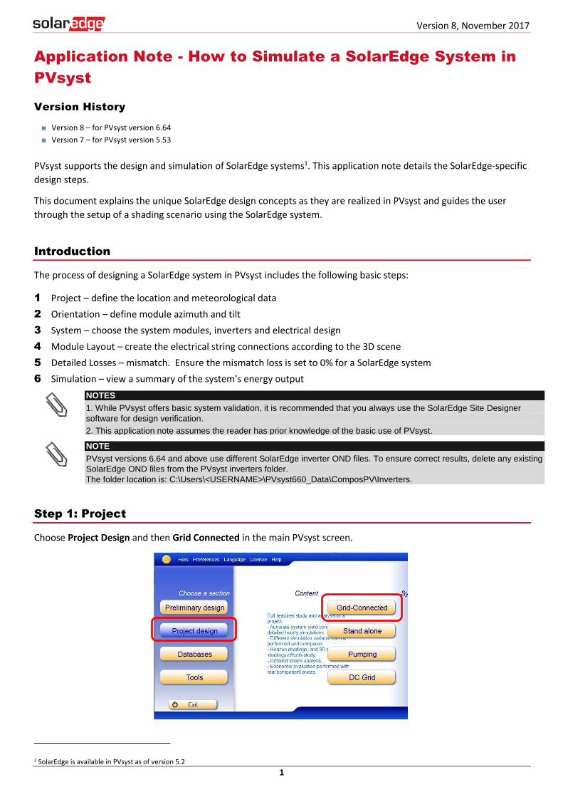
Step 1: Project
Choose Project Design and then Grid Connected in the main PVsyst screen.
1 SolarEdge is available in PVsyst as of version 5.2

2
Click on the New Project button and then click on the Choose Site button to select the correct project site and
meteorological file (the meteorological file will often be automatically associated with the chosen site).
In order to add a new site to PVsyst, click on Databases in the main PVsyst screen and then Geographical Sites.
Choose New and locate your site on the Interactive Map tab, or type the geographical location in the search box.
Click Import and then click on the Import button with the sun icon. Click OK and then Save. When prompted to
save the hourly values, click Yes and then Close and Exit. You can now choose the new meteorological site for your
project.
Step 2: Orientation
Once the geographical location and climate file have been chosen, you will define the array’s azimuth and tilt.
PVsyst offers different options to fit various types of projects, including simple fixed tilted plane, multiple
orientations (up to 8 orientations), seasonal tilt adjustments, ‘unlimited sheds’ for large systems, sun shields
(modules mounted to facades of buildings) as well as various kinds of tracking arrays, both single and double-axis.
New Project Choose Site
3
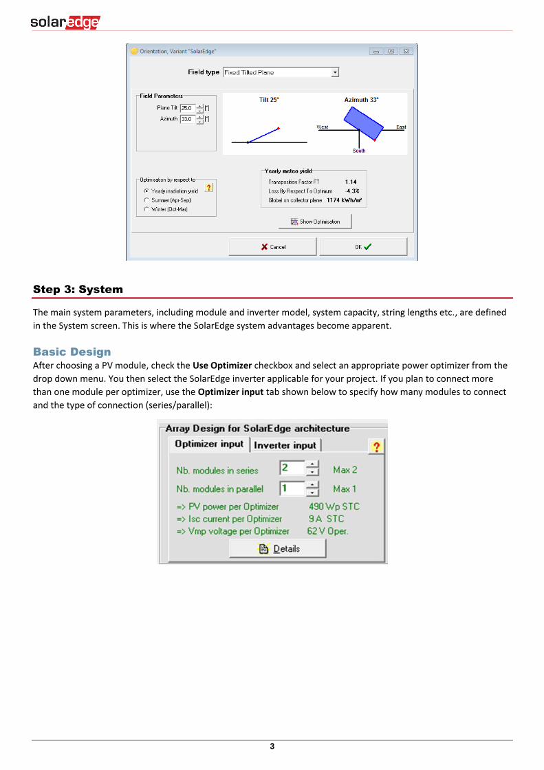
Step 3: System
The main system parameters, including module and inverter model, system capacity, string lengths etc., are defined
in the System screen. This is where the SolarEdge system advantages become apparent.
Basic Design
After choosing a PV module, check the Use Optimizer checkbox and select an appropriate power optimizer from the
drop down menu. You then select the SolarEdge inverter applicable for your project. If you plan to connect more
than one module per optimizer, use the Optimizer input tab shown below to specify how many modules to connect
and the type of connection (series/parallel):

4
The Inverter Input tab in the SolarEdge interface lists the number of power optimizers per string, not the number of
modules. So, for example, when connecting two modules per power optimizer the string length would be 20,
meaning 40 modules:
Uneven String Design
Unlike a traditional inverter, the SolarEdge system introduces a high level of design flexibility. A common limitation
of a traditional system is that all strings connecting to an MPP tracker must be of the same length. The SolarEdge
system has no such limitation since MPPT is performed at the module-level using the SolarEdge power optimizers.
Multiple strings can be connected to one inverter, regardless of length, module azimuth, tilt or module type.
In order to accommodate this capability PVsyst has added a SolarEdge-specific Strings Configuration screen. This
screen allows the allocation of any string to any inverter, according to the project needs and system design limits.
The following 3 examples explain how to create an electrical design with the SolarEdge system.
NOTE
Currently, only homogeneous strings may be designed with PVsyst. A string is considered homogeneous if it
contains only one orientation, tilt and module type. In practice, the SolarEdge system can be designed with non-
homogenous strings, meaning that different orientations, module tilts and module types can be accommodated
within a string, increasing system flexibility and ease of design.
Example 1
Consider a SolarEdge SE6000H inverter with 23 modules divided into 2 strings: one with 11 modules, and one with
12 modules.
For this design, use 2 PVsyst Sub-arrays: one for each string. Each Sub-array will have one “concerned inverter”,
because both Sub-arrays concern (connect to) the one SE6000H. One Sub-array will have a string of 12 P370 power
optimizers, and the other Sub-array will have a string of 11 P370 power optimizers. The Sub-arrays will look like this:
Click on the Strings Configuration to ensure that the system is designed correctly:

5
The “Inverters Input Specification” area shows the strings are listed correctly: one string from Sub-array #1 and one
string from Sub-array #2.
Example 2
Consider a SolarEdge system with one SE27.6K connected to 104 x 300W modules. We will use the P700 power
optimizer connected to two modules in series. This will result in a design of three strings as follows: two strings with
17 power optimizers (34 modules) and one string with 18 power optimizers (36 modules). The Sub-arrays will look
like this:
As before, each Sub-array will have one “concerned inverter” Because both Sub-arrays connect to the same inverter.
The Strings Configuration screen will look like this:
Two strings are taken from Sub-array #1 and one string is taken from Sub-array #2.
Example 3
Consider a 176 kW commercial system with four SE33.3K inverters connected to 586 300W modules. We will use the
P700 power optimizer connected to 2 modules in series. The chosen design for this project is:
Inverters 1-2: Three strings of 24 P700 (3x48 modules)

6
Inverter 3: Three strings of 25 P700 (3x50 modules)
Inverter 4: Two strings of 24 P700 (2x48 modules) and one string of 25 P700 (1x50 modules)
Although there are four inverters, there are only two string lengths, so we can design the system in two Sub-arrays,
as follows:
Note the number of “concerned inverters” in each Sub-array. The first Sub-array has 3 “concerned inverters”: this is
because the 24-optimizer strings connect to 3 inverters: inverters 1, 2 and 4. The second Sub-array has 2 “concerned
inverters”: inverters 3 and 4.
In the Strings Configuration screen, make sure the Max. number of strings is set to 3 (the common number of strings
for the inverters in this design) and click Reinitialize Inverter List. You can now adjust the string connection
according to the desired electrical design. When finished, click Adjust Sub-arrays to apply the design. If all sub-
arrays are marked by a green “OK”, the design is valid.
The result should look like this:
The strings connected to inverters 1 and 2 are all from Sub-array #1 (24xP700)
The strings connected to inverter 3 are all from Sub-array #2 (25xP700)
The strings connected to inverter 4 are from Sub-array #1 (2 strings, 24xP700) and from Sub-array #2 (1 string,
25xP700)
NOTE
In some cases, especially when oversizing the PV array as in the case above, you may need to adjust the Max.
number of strings in the Strings configuration screen to the common string length of the inverter in the design,
and click Reinitialize inverter list. Once the strings are allocated appropriately, click Adjust Sub-arrays to
finalize the design.

7
Step 4: Module Layout
The SolarEdge system minimizes the energy loss due to partial shading when compared to a traditional inverter. If
the system in question has shading of any kind (trees, chimneys, inter-row shading) the 3D physical system layout
should be designed to account for the energy loss due to shade. An accurate shading simulation will ensure the
SolarEdge advantage is reflected in the annual energy output of the system. If needed, you can refer to the PVsyst
help files for assistance in constructing a 3D shading scene.
Unlike a traditional system, in which the production of entire strings may be affected by partial shading of as little as
a few cells of one module, SolarEdge confines the effects of partial shading to the shaded modules only, thanks to its
module-level MPPT. The module-level optimization in PVsyst is taken into account when using the Module Layout
method for calculating shading electrical losses.
To activate the Module Layout functionality, use the following steps:
Once the 3D scene is constructed, click the Module Layout button in the main interface:
The Module Layout interface shows a schematic layout of the modules from the 3D scene:
In the Module Arrangement area, select the All Subfields tab, ensure the correct racking method is chosen (portrait
or landscape) and click the Set all Modules button. If the 3D scene matched the electrical design (the same number

8
of modules is designed in both of them), a new tab named Electrical will automatically open, showing the following
string allocation interface:
Click on Auto Attribution and then on Distribute All:

9
Once the modules are assigned to their respective strings (and colored), click Close. Click on Use in Simulation and
click OK to exit.

10
Step 5: Detailed Losses - Mismatch
SolarEdge eliminates all losses that result from mismatch, compared to a 2% first-year loss in a traditional system.
Mismatch losses are caused by the manufacturing tolerance of the modules, temperature differences during
operation, uneven soiling and other environmental factors such as overcast weather conditions, partially melted
snow, fallen leaves etc.
When selecting a SolarEdge inverter, PVsyst automatically sets the mismatch losses to zero. For traditional systems,
you should set this parameter to 2% by clicking the Detailed Losses button at the bottom of the System screen and
selecting the Module quality – LID – Mismatch tab.
This parameter should always remain 0% in a SolarEdge system (the default setting for a SolarEdge system).
Step 6: Simulation
Once the system parameters have been defined, click on Simulation. Upon completion of the simulation, a report
will be available for viewing and printing. In addition, the Simulation Settings screen allows you to change the time
frame of the simulation (from one day to one year), as well as exporting hourly values of various parameters
including energy, inverter efficiency, PV array’s electrical behavior and more. Depending on the complexity and size
of the system, the simulation process may take from a few seconds to over an hour.

11
Appendix A: Mismatch Growth over Time
PVsyst offers a tool that simulates the growth of mismatch loss and module degradation over time.
The mismatch loss of a traditional system will grow over time due to the un-even rate of degradation between
modules in a string. SolarEdge experiences no losses due to mismatch over the life of the system.
In order to simulate the system for a specific year of operation, activate the degradation tool from the main
interface screen: click on the Detailed Losses button and choose the Degradation tab. Any year can be
specified by the user. In this example we used year 20:
NOTE
For a SolarEdge system, the «ISC Dispersion RMS» and the «VOC dispersion RMS» should always remain zero
(the default setting).
SolarEdge System Traditional System

12
Appendix B: PVsyst Loss Parameters
PVsyst calculates several loss parameters during the simulation, as shown in the loss diagram below. This diagram
appears at the end of each PVsyst report. Following is an overview of the loss parameters, calculated successively.
Horizontal global irradiation: a combination of the global diffuse irradiance and the global beam irradiance
calculated hourly over one year on a horizontal surface
Global incident in collection plane: using a transposition model (either Perez or Hay), PVsyst increases or
decreases the horizontal global irradiation depending on the azimuth and tilt. This is the actual irradiation
reaching the module
Near Shading: irradiance loss: the loss due to direct shading (affecting the beam component of the irradiance)
and diffuse shading (affecting the diffuse component of the irradiance. For example: nearby objects such as the
next row of modules in a ground mount system reduce the diffused light, even if they do not cause direct
shading)
IAM factor on global: IAM (Incidence Angle Modifier) relates to the decrease of irradiance reaching the PV cell
due to the sun rays’ refraction when passing through the PV module antireflective coating and glass. The higher
the incident angle (with respect to the sun’s position) the higher the loss
Soiling Loss Factor: any expected loss due to soiling (dust, snow, fallen leaves etc.)

13
Effective irradiance on collectors: the remaining irradiation following the previously detailed losses, multiplied
by the PV area (the module area as defined in the PAN file)
PV Conversion: the module efficiency at STC
Array nominal energy (at STC efficiency): the PV conversion efficiency multiplied by the effective irradiance on
collectors
PV loss due to irradiance level: calculates the reduced module efficiency in low light conditions
PV loss due to temperature: reduced module performance due to temperature change. The module’s
temperature coefficients as well as the thermal loss factor affect this loss. The thermal loss factor is not a
scientifically determined value; rather it is set by the user according to experience and previous estimations. A
value of 20 W/m²k is acceptable for most systems. If the modules are embedded into a roof structure, the
value can be set to 15. When the modules are free-standing in a cool and windy location, the value can be set
to 29
Optimizer efficiency loss: the efficiency associated with the operation of the power optimizers
Shading: electrical loss according to strings: in addition to the Near Shading irradiance loss, this represents the
energy lost due to the electrical effect of shading. For example, in a traditional system with strings connected in
parallel, one shaded module can cause a whole string to be bypassed due to a voltage mismatch (in a SolarEdge
system, the loss is confined to the shaded module only)
Module quality loss: This parameter makes use of the manufacturing tolerance values in the PAN file (i.e. ±2%
tolerance). The formula used is: The lower tolerance plus a quarter of the difference between lower and higher
tolerance. So for example, for a module with a ±2% tolerance, the quality loss is [-2%+(0.25 x 4%)] = -1%.
Module array mismatch loss: The energy loss due to mismatch between modules in a string. The 2% mismatch
for traditional string inverters stems from manufacturing tolerance, un-even soiling, temperature differences
between modules, tilt or azimuth differences within the string, etc. For SolarEdge systems this loss will always
be 0%
Ohmic wiring loss: The voltage drop due to wiring resistance is calculated as one value for the whole system,
set by the user. The default value of 1.5% loss from STC is recommended. This translates to a reasonable actual
loss of around 0.6% on the DC side for most systems
Inverter loss during operation (efficiency): The inverter’s DC to AC conversion efficiency, weighted for variance
in power levels over the year
Inverter loss over nominal inv. power: The power clipping in overloading conditions (where the array produces
more DC power than the maximum AC output of the inverter)
Inverter loss due to power threshold: The loss of energy when the array operates below the inverter’s
minimum power threshold (defined in the OND file)
Inverter loss over nominal inverter voltage: The energy loss when the array is producing voltage below the
inverter’s MPP voltage range
Inverter loss due to voltage threshold: The energy loss when the array is producing voltage above the
inverter’s MPP voltage range
AC ohmic loss: As with the DC wiring loss, a recommended value of 1% AC loss with respect to the STC value
will produce around 0.5% actual energy loss
External transformer loss: Unless actual parameters are available, the default 0.1% iron loss and 1% resistive
loss are recommended