SolarEdge AC/DC Safety Switch - Solar Electric Supply · Introduction SolarEdge AC/DC Safety Switch...
19
Transcript of SolarEdge AC/DC Safety Switch - Solar Electric Supply · Introduction SolarEdge AC/DC Safety Switch...


Table of Contents
SolarEdge AC/DC Safety Switch
1
Table of Contents
Chapter 1, Introduction .............................................................................. 4
What is the AC/DC Safety Switch? ................................................................................. 5 Package Contents ............................................................................................................. 5
Chapter 2, Setting Up the AC/DC Safety Switch ...................................... 6 Mounting the Switch........................................................................................................ 7 Connecting the Switch to the Inverter.............................................................................. 9 Connecting the Switch to the External DC and AC Wires ...................................................... 10 Opening the Switch Cover ............................................................................................. 10 Connecting the AC ........................................................................................................ 11 Connecting the DC ........................................................................................................ 12 Closing the AC/DC Safety Switch Covers .................................................................... 14
Chapter 3, Replacing an Inverter ............................................................ 15
Appendix A, Technical Specifications ..................................................... 16
List of Figures
Figure 1: Attaching the AC/DC Safety Switch to its Mounting Bracket ................................. 7 Figure 2: Inserting the AC and DC Conduits ........................................................................... 8 Figure 3: Opening the AC/DC Safety Switch Cover ............................................................. 10 Figure 4: Inside the AC/DC Safety Switch ............................................................................ 11 Figure 5: Wire Lengths to Strip – AC .................................................................................... 11 Figure 6: Wire Lengths to Strip – DC .................................................................................... 13 Figure 7: Closing the AC/DC Safety Switch Covers ............................................................. 14 Figure 8: Switch Dimensions in mm ..................................................................................... 16
Important Notice
Copyright © SolarEdge Inc. All rights reserved.
No part of this document may be reproduced, stored in a retrieval system or transmitted, in
any form or by any means, electronic, mechanical, photographic, magnetic or otherwise,
without the prior written permission of SolarEdge Inc.
This document is solely for the use of SolarEdge customers and employees.

Exclusion of Liability
SolarEdge AC/DC Safety Switch
2
The material furnished in this document is believed to be accurate and reliable. However,
SolarEdge assumes no responsibility for the use of this material. SolarEdge reserves the
right to make changes to the material at any time and without notice.
You may refer to the SolarEdge website (www.solaredge.com) for the most updated version.
All company and brand products and service names are trademarks or registered trademarks
of their respective holders.
Exclusion of Liability
The general terms and conditions of delivery of SolarEdge shall apply.
The content of these documents is continually reviewed and amended,
where necessary. However, discrepancies cannot be excluded. No
guarantee is made for the completeness of these documents.
Important Safety Instructions
Save these instructions.
SAFETY NOTE:
The Inverter is ungrounded at its DC inputs.
In the USA, the installation must comply with section NEC 690.35.
In Canada, the installation must comply with the Canadian Electrical Code.
WARNING!
ELECTRIC SHOCK HAZARD! The DC conductors of this photovoltaic system are
ungrounded and may be energized at all times.
RISQUE DE CHOC ÉLECTRIQUE! Les conducteurs de DC de ce système
photovoltaïque sont sans mise à la terre et peuvent activer à tout moment.
WARNING!
Do not remove the Inverter cover before five minutes have elapsed after
disconnecting all sources of power. Otherwise, there is a risk of electric shock form
energy stored in the capacitor.
Ne pas ouvrir le couvercle de l'onduleur avant que cinq minutes ne se soient
ecoulées après coupure de toutes les sources de puissance. Sinon, il y a un risque
de choc électrique provenant de l'énergie stockée dans le capaciteur.
WARNING!
Use No. 10 AWG, 75° or 90° copper PV wire only.
Utiliser seulement des câbles PV No. 10 AWG, 75° ou 90°.

Exclusion of Liability
SolarEdge AC/DC Safety Switch
3
IMPORTANT:
The wiring methods that must be used in this installation, and which are described
below, must be in accordance with the National Electrical Code and ANSI/NFPA 70.
Les méthodes de câblages qui doivent être employées dans cette installation, et qui
sont décrites ci-dessous, doivent être conformes aux standards NEC et ANSI/NFPA
70.
IMPORTANT:
Tightening torque of terminal blocks is 1.2-1.5 Nm. (0.88-1.1 pound-foot).
IMPORTANT:
Maximum allowed ambient temperature for the Inverter in +50C. Do not mount in
direct sunlight in high ambient temperatures.

Introduction
SolarEdge AC/DC Safety Switch
4
Chapter 1
Introduction
About This Chapter
This chapter introduces the SolarEdge AC/DC Safety Switch and describes
its package contents.
This chapter contains the following sections:
What is the AC/DC Safety Switch?, page 5
Package Contents, page 5

Introduction
SolarEdge AC/DC Safety Switch
5
What is the AC/DC Safety Switch?
The AC/DC Safety Switch is a manually operated switch for disconnecting
the AC and DC power of a SolarEdge Inverter in a SolarEdge power
harvesting system.
The AC/DC Safety Switch is installed on the bottom of each Inverter. AC
and DC cables run through it and connect to the Inverter.
The AC/DC Safety Switch opens all ungrounded conductors of the circuit
to which it is connected in compliance with the National Electric Code, and
specifically NEC690.35, which addresses ungrounded PV arrays. The
AC/DC Safety Switch is rated to the operating condition of the Inverter
(32A, 600VDC and 32A 240/20VAC).
Package Contents
The following describes the contents of the AC/DC Safety Switch package:
AC/DC Safety Switch.
Front Cover of the AC/DC Safety Switch.
AC/DC Safety Switch mounting bracket.
Paper template with a drawing that indicates the places to drill the
mounting holes on the wall.
Four flat head screws for fastening the AC/DC Safety Switch to the
wall-mounting bracket.
Two washers for connecting the Safety Switch to the Inverter

Setting Up the AC/DC Safety Switch
SolarEdge AC/DC Safety Switch
6
Chapter 2
Setting Up the AC/DC
Safety Switch
About This Chapter
This chapter describes how to install and connect the AC/DC Safety
Switch.
This chapter contains the following sections:
Mounting the Switch, page 7
Connecting the Switch to the Inverter, page 9
Connecting the Switch to the External DC and AC Wires, page 10

Setting Up the AC/DC Safety Switch
SolarEdge AC/DC Safety Switch
7
Mounting the Switch
The AC/DC Safety Switch is mounted after the Inverter has been mounted,
as described in the SolarEdge Installation Guide.
1 Attach the AC/DC Safety Switch to its mounting bracket using the four
provided flat head mounting screws, as shown below:
Figure 1: Attaching the AC/DC Safety Switch to its Mounting Bracket
2 To determine the location where to drill the holes for the mounting
bracket, position the bracket against the wall or pole and push the
conduits into the Inverter inputs. Use a pencil to mark the positions
where the bracket will be screwed into the wall or pole.
Alternatively, you can use the supplied paper template to mark the
positions of the holes. The paper template has a drawing that indicates
the positions where to drill. Place the top of the paper aligned with the
bottom of the Inverter mounting bracket.
NOTES:
The conduits, hubs and fittings that are used must be suited for field wiring
systems.
The hubs and other fittings that are used must comply with UL514B.
The conduits, hubs and fittings that are used must have any one of the
following NEMA ratings: 3, 3R, 3RX, 3S, 3SX, 3X, 4X, 4, 6 and 6P for a unit
NEMA 3R rating.
Mounting Screws
Bracket
DC Conduit
AC Conduit
3 screws used to open the cover
Setting Up the AC/DC Safety Switch
SolarEdge AC/DC Safety Switch
8
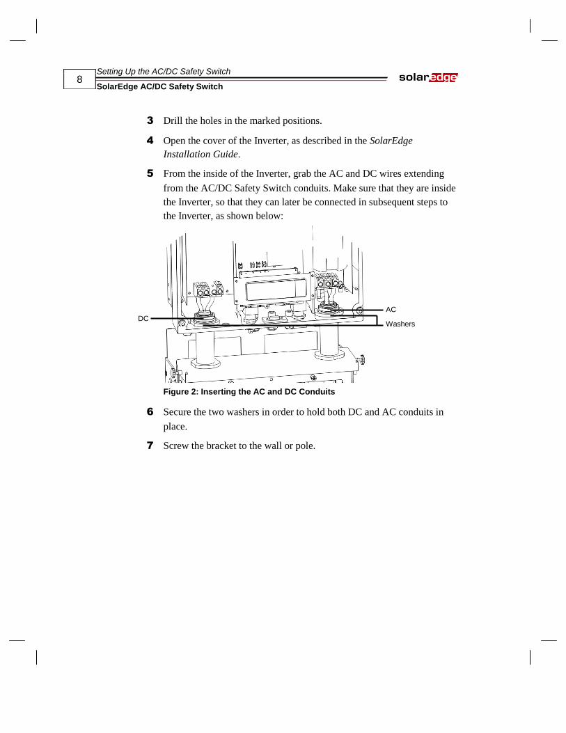
3 Drill the holes in the marked positions.
4 Open the cover of the Inverter, as described in the SolarEdge
Installation Guide.
5 From the inside of the Inverter, grab the AC and DC wires extending
from the AC/DC Safety Switch conduits. Make sure that they are inside
the Inverter, so that they can later be connected in subsequent steps to
the Inverter, as shown below:
Figure 2: Inserting the AC and DC Conduits
6 Secure the two washers in order to hold both DC and AC conduits in
place.
7 Screw the bracket to the wall or pole.
DC
AC
Washers

Setting Up the AC/DC Safety Switch
SolarEdge AC/DC Safety Switch
9
Connecting the Switch to the
Inverter
► To connect the AC/DC Safety Switch to the Inverter:
1 Connect the DC, as follows:
Connect the DC+ of the Inverter input to the red wire.
Connect the DC- of the Inverter input to the black wire.
2 Connect the AC, as follows:
Connect the red wire to Line 1 (L1) in the Inverter.
Connect the black wire to Line 2 (L2) in the Inverter.
Connect the white wire to the Neutral (N) in the Inverter.
Connect the green/yellow wire to the grounding terminal .
3 Tighten the screws of each wire terminal according to the following
torque. The tightening moment is 1.2-1.5 Nm.(0.88-1.1 pound-foot).
4 Verify that there are no whiskers in each terminal connector and that
the unused ports of the terminals are sealed.
5 Close the Inverter cover, as described in the SolarEdge Installation
Guide.

Setting Up the AC/DC Safety Switch
SolarEdge AC/DC Safety Switch
10
Connecting the Switch to the
External DC and AC Wires
Opening the Switch Cover
► To open the AC/DC Safety Switch:
1 Move the switch to the OFF position
2 Open the three screws on the front cover of the AC/DC Safety Switch,
as shown below:
Figure 3: Opening the AC/DC Safety Switch Cover
Open these screws

Setting Up the AC/DC Safety Switch
SolarEdge AC/DC Safety Switch
11
3 Remove the AC/DC Safety Switch cover.
Figure 4: Inside the AC/DC Safety Switch
Connecting the AC
Use any of the AC side conduit inputs. Each punch-out opening has two
sizes: ¾” and 1”.
1 Strip off the isolation and expose the three wires in the AC cable, as
follows:
The lengths of the wires to strip are as follows:
50mm 8mm
Figure 5: Wire Lengths to Strip – AC
Strip 8 mm (1/3'') for contact.
Individual cable length 50 mm (2'').
WARNING!
Make sure to connect the equipment grounding first.
Veillez à relier le conducteur de PE (la terre) d'abord.
DC Side Conduits
AC Side Conduits
AC Connections DC Connections
Equipment Grounding Terminal

Setting Up the AC/DC Safety Switch
SolarEdge AC/DC Safety Switch
12
2 Connect the wires to the appropriate terminal connectors according to
their labels: GND, L1 and L2. Optionally, N, as well.
Line 1 (L1), which is typically red.
Line 2 (L2), which is typically black.
Neutral (N) which is typically white. You may optionally connect
the Neutral wire for monitoring split phase balance.
Equipment grounding conductors, can be bare, green or green
with yellow stripe.
Connect equipment grounding to the grounding terminal.
3 Tighten the screws of each wire terminal according to the following
torque. The tightening moment is 1.2-1.5 Nm.(0.88-1.1 pound-foot).
4 Verify that there are no whiskers in each terminal connector and that
the unused ports of the terminals are sealed.
Connecting the DC
Use any of the DC side conduit inputs. Each punch-out opening has two
sizes ¾” and 1”.
1 Connect the DC connectors from the photovoltaic installation to the
DC+ and DC- connectors as shown in Figure 4.
Two strings may be connected in parallel to both DC inputs of the
Inverter. They are simply wired together in the terminal block inside.
2 Connect the DC equipment grounding to the equipment grounding
terminal block.
If more than two strings are required, they can be connected in parallel
in an external combiner Box before connecting a unified DC
connection to the Inverter.
NOTE:
If more than two strings are connected each should be properly fused on both
DC+ and DC- according to NEC690.35(B).

Setting Up the AC/DC Safety Switch
SolarEdge AC/DC Safety Switch
13
NOTE:
SolarEdge’s fixed input voltage architecture enables the parallel strings to be of
different lengths. Therefore, they do not necessarily need to be connected to an
identical number of power optimizers.
The lengths of the wires to strip are as follows:
50mm 8mm
Figure 6: Wire Lengths to Strip – DC
Strip 8 mm (1/3'') to enable contact
Each cable length is 50 mm (2'')
CAUTION:
Ensure that the + wire is connected to the + terminal connector and that the -
wire is connected to the - terminal connector.
S'assurer que le câble + est connecté à la borne + et que le câble - est
connecté à la borne -.
3 Tighten the screws of each wire terminal according to the following
torque. The tightening moment for the terminals is 1.2-1.5 Nm.(0.88-
1.1 pound-foot).

Setting Up the AC/DC Safety Switch
SolarEdge AC/DC Safety Switch
14
Closing the AC/DC Safety Switch
Covers
1 Close the AC/DC Safety Switch cover by putting back the three screws.
2 Install the decorative plastic cover using the three screws.
Figure 7: Closing the AC/DC Safety Switch Covers
You may now continue in the SolarEdge Installation Guide from
Chapter 5, Commissioning the Installation.

Replacing an Inverter
SolarEdge AC/DC Safety Switch
15
Chapter 3
Replacing an Inverter
About This Chapter
This chapter describes how to replace an Inverter.
An Inverter can be replaced without opening or removing the AC/DC
Safety Switch, as described below.
1 Turn the Inverter’s ON/OFF switch on the bottom of the Inverter to
OFF. Wait until the LCD indicates that the DC voltage is safe or wait at
least five minutes before continuing to the next step.
2 Turn the AC/DC Safety Switch OFF.
3 Open the Inverter cover.
4 Disconnect the DC and AC wires from the Inverter.
5 Remove the Inverter from the mounting bracket.
6 Place the new Inverter on the mounting bracket and install the DC and
AC wires, as described in this manual.
You may now continue setting up the new Inverter and re-pairing the new
Inverter to the existing power optimizers, as described in Chapter 5,
Commissioning the Installation of the SolarEdge Installation Guide.
NOTE:
If you remove the old Inverter and do not immediately install a new one, then:
Lock the AC/DC Safety Switch to the OFF position using a padlock on the switch.
Use insulation tape to isolate each of the AC and DC wires.
Seal the open conduits using duck tape.

Technical Specifications
SolarEdge AC/DC Safety Switch
16
Appendix A
Technical Specifications
About This Appendix
This appendix provides the technical specifications of the SolarEdge
AC/DC Safety Switch.
Input
Maximum DC voltage 600 Vdc
Maximum DC current 32 Vac
Nominal AC voltage 240/208 Vac
Nominal AC current 32 Adc
Ambient temperature -25 - 65 degC
Figure 8: Switch Dimensions in mm

Technical Specifications
SolarEdge AC/DC Safety Switch
17