Application Note Design a SolarEdge System using PV SOL
8
Version 3.0, March 2021 1 Application Note - How to Design a SolarEdge System Using PV*SOL Application Note - How to Design a SolarEdge System Using PV*SOL This application note describes how to simulate a SolarEdge system in PV*SOL. NOTE This application note assumes the reader has prior knowledge of the basic use of PV*SOL. NOTE Although PV*SOL performs basic SolarEdge design validation, it is highly recommended to use the SolarEdge Designer software for system validation. Contents Introduction ................................................................................................................................................................................................................... 1 Starting a new Project ................................................................................................................................................................................................ 2 System Planning with 3D Visualization ................................................................................................................................................................. 2 Example #1 ........................................................................................................................................................................................................................... 2 Example #2 ........................................................................................................................................................................................................................... 4 System Planning Without 3D Visualization.......................................................................................................................................................... 6 Introduction The SolarEdge system’s advantages become clear when designing a 3D shading scene using PV*SOL and comparing the same design to a traditional inverter. Concerns over string azimuth, tilt or partial shading can be disregarded when designing a SolarEdge system. You may configure a PV system using one of the two methods offered by PV*SOL: With 3D shading visualization: The system is designed visually. Electrical design and shading calculations are performed in the 3D scene Without 3D shading visualization: The system is designed by filling in the electrical parameters only
Transcript of Application Note Design a SolarEdge System using PV SOL
Version 3.0, March 2021 1
Application Note - How to Design a SolarEdge System Using PV*SOL
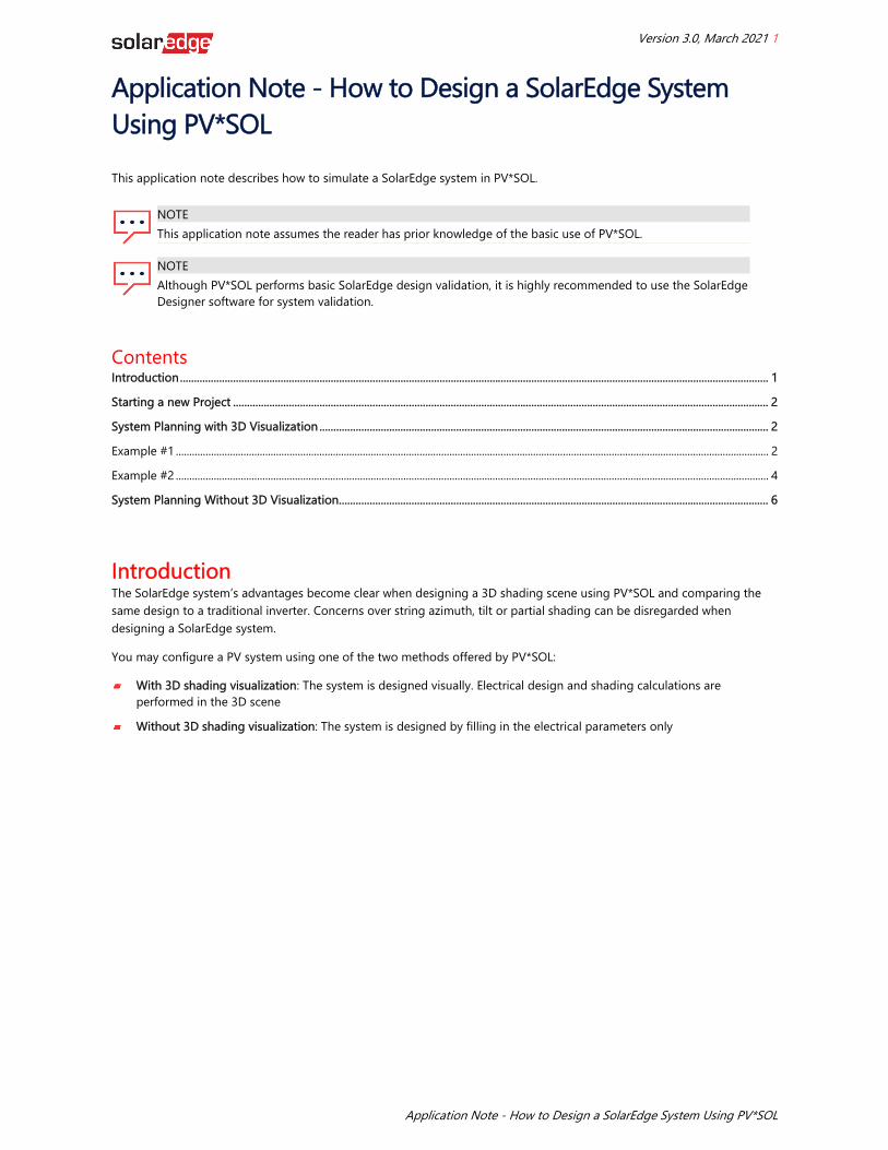
Application Note - How to Design a SolarEdge System Using PV*SOL This application note describes how to simulate a SolarEdge system in PV*SOL.
NOTE This application note assumes the reader has prior knowledge of the basic use of PV*SOL.
NOTE Although PV*SOL performs basic SolarEdge design validation, it is highly recommended to use the SolarEdge Designer software for system validation.
Contents Introduction ................................................................................................................................................................................................................... 1 Starting a new Project ................................................................................................................................................................................................ 2 System Planning with 3D Visualization ................................................................................................................................................................. 2 Example #1 ........................................................................................................................................................................................................................... 2 Example #2 ........................................................................................................................................................................................................................... 4 System Planning Without 3D Visualization .......................................................................................................................................................... 6
Introduction The SolarEdge system’s advantages become clear when designing a 3D shading scene using PV*SOL and comparing the same design to a traditional inverter. Concerns over string azimuth, tilt or partial shading can be disregarded when designing a SolarEdge system. You may configure a PV system using one of the two methods offered by PV*SOL:
With 3D shading visualization: The system is designed visually. Electrical design and shading calculations are performed in the 3D scene
Without 3D shading visualization: The system is designed by filling in the electrical parameters only

Starting a new Project 2
Application Note - How to Design a SolarEdge System Using PV*SOL
Starting a new Project Start a new project as follows: 1. From the File menu select New Project. 2. Optionally fill in the project data parameters.
3. Click the Continue arrow or the System Type, Climate and Grid button circled below in the tool bar.
4. Select the Country and Location:
5. To specify a location that is not on the list, click Open climate data selection (circled above), and add a new location.
System Planning with 3D Visualization Example #1 1. In the Type of Design section, check Use 3D Design:
2. In the Type of System, Select the Grid Connected PV system. 3. Click the Continue arrow or click 3D Design in the toolbar. 4. In the 3D Design section, click Edit to design the system.

System Planning with 3D Visualization 3
Application Note - How to Design a SolarEdge System Using PV*SOL
5. Proceed with creating the 3D model of the project and place the modules in the scene. For help with 3D model building and project setup in PV*SOL, refer to the PV*SOL help and manuals available on the Valentin Software website (http://www.valentin.de/en). The following is an example 5.7kW project that has two orientations and partial shading from a chimney. The system comprises 19 X 300W modules (12 modules facing South and 7 modules facing West). The SolarEdge system will comprise of one string of 19 P300 power optimizers, spanning both orientations, connected to an SE5000H inverter.
6. Select the Module Configuration tab, as circled below, to configure the SolarEdge power optimizers.
7. Click Configure all Unconfigured Modules circled above. 8. To connect both orientations as one string, in the inverter configuration window Ctrl-click to select Roof Area South
and Roof Area West, and then click Configure module areas together.
9. Check Polystring Configuration. 10. From the inverter drop-down list, select SolarEdge as the inverter manufacturer and then select the required inverter. 11. Select the appropriate power optimizer to fit the chosen module (in this case, the SE5000H inverter mated with the
P300 using a 1:1 connection). Please refer to the SolarEdge Designer to find the correct power optimizer for the modules in your project. The SolarEdge system allows multiple orientations to exist within one string. The correct design for this roof is one string of 19 modules, spanning both orientations.
12. To allow one string to span over multiple orientations, click Add Row to insert an additional orientation and check the option Connect strings with the same number in series. Make sure the new row refers to the same string (in this case, String 1). The final electrical design will look like this:

System Planning with 3D Visualization 4
Application Note - How to Design a SolarEdge System Using PV*SOL
13. Click OK to return to the main 3D interface. The modules now indicate the string design (in this case, one string only):
14. Click Results to run the simulation:
15. Click View Presentation and choose the format to which you would like to export the results.
Example #2 This example shows how to create the electrical design for a rooftop with several orientations. To make the design easier, we can group roofs that have the same tilt and azimuth together electrically. Consider the following rooftop with 384 440W modules. While there are twelve roof facets, there are only four orientations, which can make our electrical design easier.

System Planning with 3D Visualization 5
Application Note - How to Design a SolarEdge System Using PV*SOL
1. Select the Module Configuration tab, click Define module areas for configuration.
2. The Define Module Areas window opens and lists all module areas across all buildings. You can see that there are only
4 orientations:
3. You will isolate each orientation and string it individually. In this example, isolate the modules facing 90 degrees and
click Configure:

System Planning Without 3D Visualization 6
Application Note - How to Design a SolarEdge System Using PV*SOL
4. In the design window that opens, type Ctrl+Click to select and highlight both roofs and then click Configure module areas together. This allows you to treat both roofs as if they are one.
5. Now you can configure the system as you would normally. Note that you must choose which string belongs to which
roof in our design:
6. Repeat this process for the remaining orientations to configure the entire project.
System Planning Without 3D Visualization The steps in this section show you how to design a system when a 3D shading scene is not available. We will use the same residential system as that which was used as an example in the previous section. 1. In the Type of Design section, clear the checkbox Use 3D Design.
2. In the Type of System, Select the Grid Connected PV system. 3. Click PV Modules in the toolbar:
4. There are 2 Module Areas (orientations) that need to be created: South, with 12 modules, and West, with 7 modules.
Insert the following parameters for Module Area 1 (South): Module manufacturer and model: Jinko Solar JKM300M-60 (the modules used in this example) Number of PV modules: 12 Orientation: 180° Inclination: 27° Installation type: In this case, you can select Roof Parallel
System Planning Without 3D Visualization 7
Application Note - How to Design a SolarEdge System Using PV*SOL
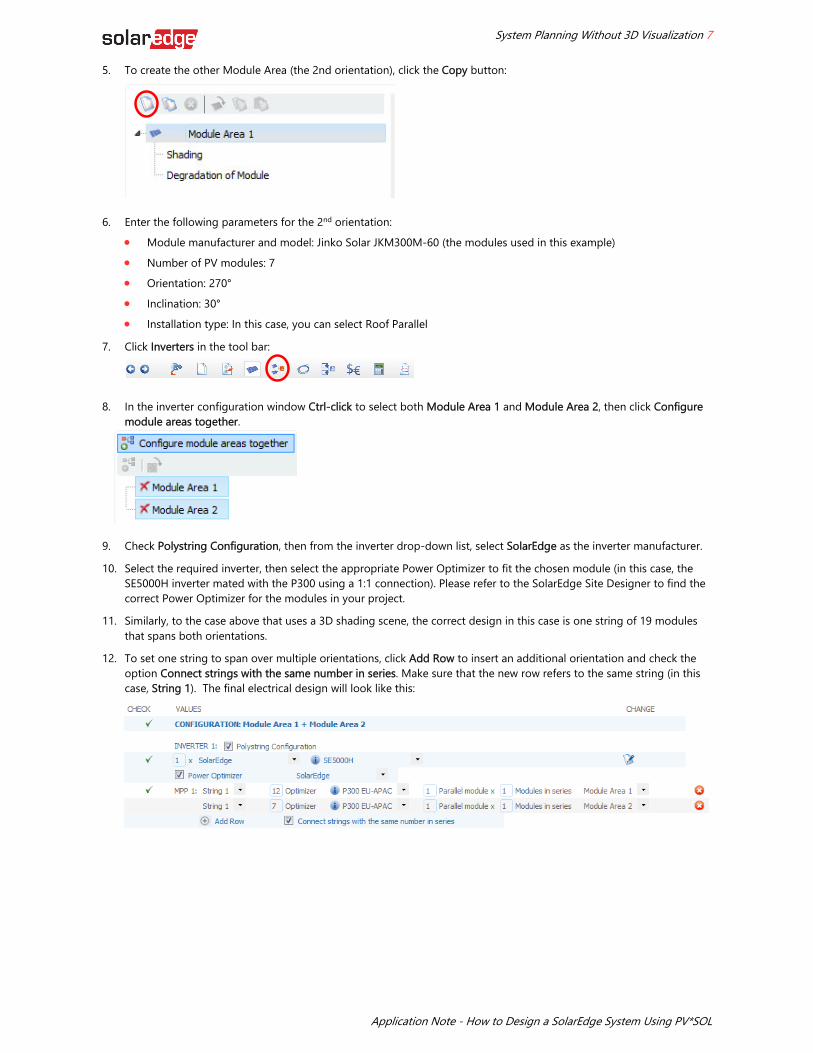
5. To create the other Module Area (the 2nd orientation), click the Copy button:
6. Enter the following parameters for the 2nd orientation:
Module manufacturer and model: Jinko Solar JKM300M-60 (the modules used in this example) Number of PV modules: 7 Orientation: 270° Inclination: 30° Installation type: In this case, you can select Roof Parallel
7. Click Inverters in the tool bar:
8. In the inverter configuration window Ctrl-click to select both Module Area 1 and Module Area 2, then click Configure
module areas together.
9. Check Polystring Configuration, then from the inverter drop-down list, select SolarEdge as the inverter manufacturer. 10. Select the required inverter, then select the appropriate Power Optimizer to fit the chosen module (in this case, the
SE5000H inverter mated with the P300 using a 1:1 connection). Please refer to the SolarEdge Site Designer to find the correct Power Optimizer for the modules in your project.
11. Similarly, to the case above that uses a 3D shading scene, the correct design in this case is one string of 19 modules that spans both orientations.
12. To set one string to span over multiple orientations, click Add Row to insert an additional orientation and check the option Connect strings with the same number in series. Make sure that the new row refers to the same string (in this case, String 1). The final electrical design will look like this:

System Planning Without 3D Visualization 8
Application Note - How to Design a SolarEdge System Using PV*SOL
13. Click Results to run the simulation:
14. Click View Presentation and choose the format to which you would like to export the results.