Application Guide - Beckman Coulter The SDS-MW Analysis Kit is designed for the separation of...
34
A51970AD January 2014 Application Guide PA 800 plus Pharmaceutical Analysis System SDS-MW Analysis Beckman Coulter, Inc. 250 S. Kraemer Blvd. Brea, CA 92821 U.S.A.
Transcript of Application Guide - Beckman Coulter The SDS-MW Analysis Kit is designed for the separation of...

Application Guide
PA 800 plus
Pharmaceutical Analysis
System
SDS-MW Analysis
January 2014
Beckman Coulter, Inc.
250 S. Kraemer Blvd.
Brea, CA 92821 U.S.A.
A51970AD
Application Guide
PA 800 plus Pharmaceutical Analysis System
SDS-MW Analysis
PN A51970AD (January 2014)
© 2009-2014 Beckman Coulter, Inc. All rights reserved.
Made in U.S.A.
Beckman Coulter, Inc. grants a limited non-exclusive
license to the owner or operator of a PA 800 plus
instrument to make a copy, solely for laboratory use,
of any portion or all of the online help and electronic
documents shipped with the PA 800 plus instrument.
Beckman Coulter and the stylized logo are trademarks of
Beckman Coulter, Inc. are registered in the USPTO.
All other trademarks, service marks, products, or services
are trademarks or registered trademarks of their
respective holders.
Find us on the World Wide Web at:
www.beckmancoulter.com
Printed in U.S.A.

Revision History
Initial Issue, A51970AA, April 2009
32 Karat Software version 9.1
PA 800 plus Software version 1.1
PA 800 plus Firmware version 9.0
First Revision, A51970AB, December 2009
Revised corporate address.
Second Revision, A51970AC, February 2011
32 Karat Software version 9.1 patch
PA 800 plus Software version 1.1 patch
PA 800 plus Firmware version 9.2
Numerous syntax and grammatical edits
Third Revision, A51970AD, January 2014
Dimension & instruction edit
A51970AD iii

Revision History
A51970AD1-iv

Safety Notices
Symbols and Labels
Introduction
The following is a description of symbols and labels used on the Beckman Coulter PA 800 plus Pharmaceutical Analysis System or shown in this manual.
WARNING
If the equipment is used in a manner not specified by Beckman Coulter, Inc., the
protection provided by the instrument may be impaired.
General Biohazard Symbol
This caution symbol indicates a possible biohazard risk from patient specimen contamination.
Caution, Biohazard Label
This caution symbol indicates a caution to operate only with all covers in position to decrease risk of personal injury or biohazard.
A51970AD v

Safety Notices
Symbols and Labels
Caution, Moving Parts Label
This caution symbol warns the user of moving parts that can pinch or crush.
High Voltage Electric Shock Risk Symbol
This symbol indicates that there is high voltage and there is a risk of electric shock when the user works in this area.
Class 1 Laser Caution Label
A label reading “Complies with 21 CFR 1040.10 and 1040.11 except for deviations pursuant to Laser Notice No. 50, dated June 24, 2007” is found near the Name Rating tag. The laser light beam is not visible.
CAUTIONPARTS MOVEAUTOMATICALLY
A015081L.EPS
144557-AB
A016352L.EPS
A51970ADvi

Safety Notices
Symbols and Labels
Sharp Object Label
A label reading “CAUTION SHARP OBJECTS” is found on the PA 800 plus.
Recycling Label
This symbol is required in accordance with the Waste Electrical and Electronic Equipment (WEEE) Directive of the European Union. The presence of this marking on the product indicates:
1. The device was put on the European Market after August 13, 2005.
2. The device is not to be disposed of via the municipal waste collection system of any member state of the European Union.
It is very important that customers understand and follow all laws regarding the proper decontamination and safe disposal of electrical equipment. For Beckman Coulter products bearing this label, please contact your dealer or local Beckman Coulter office for details on the take back program that facilitates the proper collection, treatment, recovery, recycling, and safe disposal of this device.
Disposal of Devices Containing Mercury Components
This product contains a mercury-added part. Recycle or dispose of according to local, state, or federal laws. It is very important that you understand and comply with the safe and proper disposal of devices containing mercury components (switch, lamp, battery, relay, or electrode). The mercury component indicator label can vary depending on the type of device.
CAUTIONSHARP OBJECTS
A16558-AA
A016351L.EPS
A51970AD vii

Safety Notices
Symbols and Labels
Restriction of Hazardous Substances (RoHS) Labels
These labels and materials declaration table (the Table of Hazardous Substance's Name and Concentration) are to meet People's Republic of China Electronic Industry Standard SJ/T11364-2006 "Marking for Control of Pollution Caused by Electronic Information Products" requirements.
China RoHS Caution Label — This label indicates that the electronic information product contains certain toxic or hazardous substances. The center number is the Environmentally Friendly Use Period (EFUP) date, and indicates the number of calendar years the product can be in operation. Upon the expiration of the EFUP, the product must be immediately recycled. The circling arrows indicate the product is recyclable. The date code on the label or product indicates the date of manufacture.
China RoHS Environmental Label — This label indicates that the electronic information product does not contain any toxic or hazardous substances. The center “e” indicates the product is environmentally safe and does not have an Environmentally Friendly Use Period (EFUP) date. Therefore, it can safely be used indefinitely. The circling arrows indicate the product is recyclable. The date code on the label or product indicates the date of manufacture.
A51970ADviii
Safety Notices
Symbols and Labels
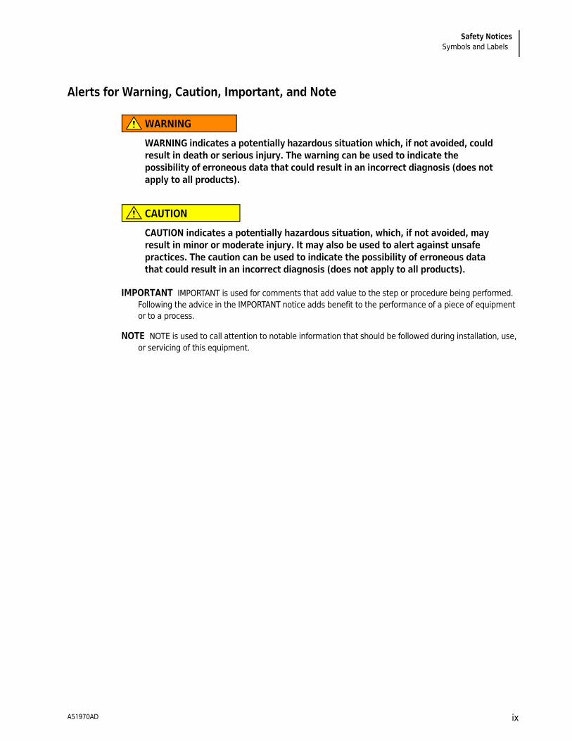
Alerts for Warning, Caution, Important, and Note
WARNING
WARNING indicates a potentially hazardous situation which, if not avoided, could
result in death or serious injury. The warning can be used to indicate the
possibility of erroneous data that could result in an incorrect diagnosis (does not
apply to all products).
CAUTION
CAUTION indicates a potentially hazardous situation, which, if not avoided, may
result in minor or moderate injury. It may also be used to alert against unsafe
practices. The caution can be used to indicate the possibility of erroneous data
that could result in an incorrect diagnosis (does not apply to all products).
IMPORTANT IMPORTANT is used for comments that add value to the step or procedure being performed.
Following the advice in the IMPORTANT notice adds benefit to the performance of a piece of equipment
or to a process.
NOTE NOTE is used to call attention to notable information that should be followed during installation, use,
or servicing of this equipment.
A51970AD ix

Safety Notices
Symbols and Labels
A51970ADx

Contents
Revision History, iii
Safety Notices, v
Symbols and Labels, v
CHAPTER 1: Introduction, 1-1Protein Size Standard, 1-1Internal Standard, 1-1
Intended Use, 1-2
Materials and Reagents, 1-2
Storing the Assay Components, 1-3Reagents, 1-3Materials Required but Not Provided by Beckman Coulter, 1-3Beckman Coulter Consumables, 1-3
Preparing the PA 800 plus Instrument, 1-4Installing the Capillary, 1-4Cleaning the Interface, 1-4Inserting the Cartridge/Calibrating the PDA, 1-5
Sample Preparation, 1-5Preparation of SDS-MW Size Standard, 1-5Preparation of Protein Sample, 1-6
Desalting the Protein Sample, 1-6Protein Sample Concentration, 1-6Reducing the Protein Sample, 1-6Non-reduced Protein Sample Preparation, 1-7
Preparing Alkylation Reagent, 1-7Preparing the Sample, 1-7
Sample Vial Setup, 1-8
Buffer Vial Preparation and Loading, 1-9Preparing the Reagent Vials, 1-9
Tray Configuration, 1-11Inlet Buffer Tray, 1-11Outlet Buffer Tray, 1-12
A51970AC xi

Contents
Running the Assay, 1-12Launching the SDS MW Instrument, 1-12Conditioning a New Capillary, 1-13
Running SDS-MW Size Standard and Test Samples, 1-14
Checking the Separation Results, 1-16Estimating Protein Molecular Weights, 1-16
Troubleshooting Guide, 1-17
CHAPTER 2: Instrument and Detector Initial Conditions, 2-1Instrument Initial Conditions (All Methods), 2-1Detector Initial Conditions (All Methods), 2-2Capillary Conditioning Method (SDS MW Conditioning - PA 800
plus.met), 2-2SDS-MW Separation Method, 2-3Shutdown Method, 2-3
A51970ACxii
CHAPTER 1
SDS-MW Analysis Kit
Introduction
Capillary electrophoresis (CE) has become an effective replacement for manual slab gel electrophoresis processes due to its automation, quantitation, fast speed, and high efficiency. Many biomolecules, such as proteins, carbohydrates, and nucleic acids are separated by molecular sieving electrophoresis using gel matrices, a technique referred to as capillary gel electrophoresis (CGE). The separation results from the differential migration of the analyte through a gel matrix. In this case, smaller molecules will move faster than large molecules through the separation gel. For polypeptides and proteins, it is necessary to denature the sample in the presence of SDS, an anionic detergent that binds the proteins in a constant ratio of 1:1.4 of protein. The constant mass-to-charge property of the SDS-bound proteins allows separation according to differences in protein molecular weight.
The SDS-MW Analysis Kit is designed for the separation of protein-SDS complexes using a replaceable gel matrix. The gel is formulated to provide an effective sieving range of approximately 10 kDa to 225 kDa. Within this size range, the logarithm of protein molecular mass is linear with its reciprocal electrophoretic mobility. Therefore, the molecular weight of an unknown protein may be estimated from a standard curve of known protein sizes. This kit can also be used to quantify the amount of protein and to determine the purity of a protein product.
NOTE This application guide has been validated for use on the PA 800 Enhanced Systems and the PA 800
plus Pharmaceutical Analysis Systems.
NOTE The PA 800 plus series systems must be equipped with a photodiode array (PDA) detector to perform
this assay.
Protein Size Standard
The SDS-MW Size Standard contains 10, 20, 35, 50, 100, 150, and 225 kDa proteins. The SDS-MW Size Standard is used to calibrate the gel to estimate the protein molecular weight of your sample. It also provides confirmation of the resolving power of your experiment.
Internal Standard
A 10 kDa protein is used as a mobility marker. The mobility of all protein samples are calculated relative to this mobility marker allowing for more accurate size estimation and analyte identification.
A51970AD 1-1

SDS-MW Analysis Kit
Intended Use
Intended Use
The SDS-MW Analysis Kit is for laboratory use only.
CAUTION
Refer to the Material Safety Data Sheets (MSDS) information, available at
www.BeckmanCoulter.com, regarding the proper handling of materials and
reagents. Always follow standard laboratory safety guidelines.
Materials and Reagents
Table 1.1 Contents of this Kit (reorder # 390953)
Component Quantity
Capillary, 50 µm I.D. bare-fused silica 2
SDS-MW Gel Buffer - proprietary formulation, pH 8, 0.2% SDS 140 mL
SDS-MW Sample Buffer - 100 mM Tris-HCl pH 9.0, 1%SDS 50 mL
SDS-MW Size Standard (10 to 225 kDa, 16 mg/mL) 100 µL
Internal Standard, 10 kDa, protein 5mg/mL 0.4 mL
Acidic Wash Solution (0.1 N HCl) 100 mL
Basic Wash Solution (0.1 N NaOH) 100 mL
Table 1.2 Replacement Reagents
Component Quantity Part Number
Capillary, 50 µm I.D. bare-fused silica pkg of 3 338451
SDS-MW Gel Buffer - proprietary formulation, pH 8, 0.2% SDS pkg of 4 A30341
SDS-MW Size Standard (10 to 225 kDa, 16 mg/mL) pkg of 3 A22196
Internal Standard, 10 kDa protein, 5mg/mL pkg of 1 A26487
A51970AD1-2

SDS-MW Analysis Kit
Storing the Assay Components 1
Storing the Assay Components
Reagents
Upon receipt, store protein Sizing Standard and Internal Standard at 2°C to 8°C. The Capillary, Sample Buffer, and Gel Buffer can be stored at room temperature. If precipitation is noted in the Gel Buffer and Sample Buffer, stir until precipitation is completely dissolved.
Materials Required but Not Provided by Beckman Coulter
Beckman Coulter Consumables
Component Part Number
2-mercaptoethanol Sigma-Aldrich, PN M7154,
M6250
Water Bath (37°C to 100°C) or Heat Block
Centricon YM-10 Centrifugal Filter Unit Millipore, PN 4205
Iodoacetamide Sigma-Aldrich, PN I-1149
Parafilm
Sonicator
Vortexer
Pipets of various sizes with corresponding pipet tips
Micro-centrifuge
Component Part Number
0.5mL Micro-centrifuge Capped Vials (pack of 500) 344319
1.5 mL Centrifuge Tubes (pack of 500) 357448
Universal Plastic Vials (pack of 100) A62251
Universal Rubber Vial Caps - blue (pack of 100)a
a. Vial caps are one time use only and are not intended for re-use.
A62250
200 µL Micro Vials (pack of 50) 144709
Double-deionized (DDI) water
A51970AD 1-3

SDS-MW Analysis Kit
Preparing the PA 800 plus Instrument
Preparing the PA 800 plus Instrument
NOTE Before proceeding, you must understand the following procedures as described in the PA 800 plus
System Maintenance Guide (PN A51964AD or the most current version):
• Capillary Replacement
• Installation of the PDA detector
• How to calibrate the PDA detector
• How to load and unload trays
Installing the Capillary
1 Install a 50 µm I.D. bare fused-silica capillary into a PA 800 plus cartridge set for a total capillary
length of 30.2 cm.
The SDS-MW assay is optimized using a 30.2 cm capillary with a 20.0 cm effective length from the sample introduction inlet to the center of the detector window.
2 Use the 100 x 200 µm capillary aperture for this installation.
To get good reproducibility from capillary to capillary and accurate mobility assignments, it is important to adhere to the capillary pre-measurement procedure.
NOTE The cut ends of capillaries should be inspected carefully under magnification. The cut must be
clean (not jagged) and perpendicular to the capillary length (not angled). Poor cuts will result in poor
resolution and poor sample loading.
3 Turn off the PA 800 plus instrument and install the PDA detection module.
4 Turn on the instrument and permit the UV lamp to warm up for at least 30 minutes prior to
experimentation.
Cleaning the Interface
Following System Maintenance Guide A51964AD or latest revision, carefully clean the electrodes, capillary ends, and interface block either every other day or after the finish of the sequence. The SDS gel buffer is very viscous and will accumulate on the electrodes, capillary ends, opening levers, and interface block if regular and thorough cleaning is not employed. Gel accumulation may cause various modes of system failure, including broken capillaries and bent electrodes, vial jams, and missed injections.
A51970AD1-4

SDS-MW Analysis Kit
Sample Preparation 1
Inserting the Cartridge/Calibrating the PDA
Insert the cartridge into the system. Close the front panel and calibrate the PDA detector. This procedure should be employed daily or any time the cartridge is replaced.
Sample Preparation
Preparation of SDS-MW Size Standard
1 Remove SDS-MW Size Standard from refrigerator. Leave at room temperature for 15 minutes
before starting sample preparation.
2 Mix the standard thoroughly and centrifuge briefly in a standard microfuge.
3 Pipette 10 µL of Size Standard into a micro-centrifuge vial.
4 Add 85 µL of Sample Buffer into the micro-centrifuge vial.
5 Add 2 µL of Internal Standard into the micro-centrifuge vial.
6 Add 5 µL of 2-mercaptoethanol. Cap the vial tightly, seal with Parafilm, and mix thoroughly.
7 Heat mixture in a water bath at 100°C for three minutes.
8 Place the vial in a room-temperature water bath to cool for five minutes before injection. The
sample will remain stable for approximately 24 hours.
A51970AD 1-5

SDS-MW Analysis Kit
Sample Preparation
Preparation of Protein Sample
Desalting the Protein Sample
The signal intensity and resolution of this kit are sensitive to the salt concentration in the protein sample. Generally, if the final salt concentration is above 50 mM, the sample loading efficiency will be reduced. The sample should be desalted with a Centricon column using the following procedure:
1 Add 1 mL of protein sample to a Centricon YM-10, then add 1 mL SDS-MW sample buffer into
the Centricon.
2 Centrifuge at 7,000 g for 20 minutes.
3 Add 2 mL of sample buffer. Centrifuge at 7,000 g for 20 minutes.
4 Insert the Centricon upside-down to drain the suspended protein solution (in the filter
membrane) into a new vial and centrifuge for three minutes at 5,000 g.
5 Transfer the collected protein to an appropriate sterile tube. Add sample buffer to give a final
volume of 1 mL.
Protein Sample Concentration
After the addition of the SDS-MW Sample Buffer, the total protein concentration should be within the range of 0.2 mg/mL to 2 mg/mL. For best results, the recommended protein concentration is 1 mg/mL. If the protein concentration is too high, it can result in insufficient SDS binding, giving broad peaks and poor resolution. On the other hand, if the protein concentration is too low, a low signal will be observed.
Reducing the Protein Sample
Reduction of the disulfide bonds will provide a more accurate assessment of the molecular weight of a protein, and will allow you to gain additional structural information on a given protein. In this case:
1 Dilute the sample with the SDS-MW Sample buffer for a total 95 µL volume to give a final protein
concentration range of 0.2 mg/mL to 2 mg/mL.
2 Add 2 µL of Internal Standard.
A51970AD1-6

SDS-MW Analysis Kit
Sample Preparation 1
3 Add 5 µL of 2-mercaptoethanol. Cap the vial tightly, seal with Parafilm, and mix thoroughly.
4 Heat mixture in a water bath at 100°C for 3 minutes.
5 Place the vial in a room-temperature water bath to cool for 5 minutes before injection.
Non-reduced Protein Sample Preparation
Comparison of the reduced versus non-reduced state of a protein can yield important structural information. In this case, it is a good idea to alkylate your protein sample to minimize any heterogeneity created from partial auto-reduction of your protein. The following procedure is recommended.
Preparing Alkylation Reagent
A 250 mM solution of iodoacetamide (IAM) is recommended as an alkylation reagent. The solution is stable for approximately 24 hours at room temperature.
1 Weigh out 46 mg of IAM and place in a micro-centrifuge vial.
2 Add 1 mL of DDI water to a sample vial. Cap the vial tightly and mix thoroughly.
Preparing the Sample
1 Dilute the sample with the SDS-MW Sample Buffer for a total 95 µL volume to give a final
protein concentration range of 0.2 mg/mL to 2 mg/mL.
2 Add 2 µL of Internal Standard.
3 Add 5 µL of IAM solution.
4 Cap the vial tightly, seal with Parafilm, and mix thoroughly.
5 Heat mixture in a water bath at 70°C for 3 minutes.
A51970AD 1-7
SDS-MW Analysis Kit
Sample Vial Setup
6 Place the vial in a room-temperature water bath to cool for 5 minutes before injection.
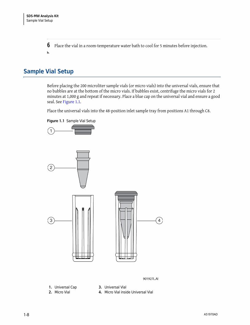
Sample Vial Setup
Before placing the 200 microliter sample vials (or micro vials) into the universal vials, ensure that no bubbles are at the bottom of the micro vials. If bubbles exist, centrifuge the micro vials for 2 minutes at 1,000 g and repeat if necessary. Place a blue cap on the universal vial and ensure a good seal. See Figure 1.1.
Place the universal vials into the 48-position inlet sample tray from positions A1 through C8.
Figure 1.1 Sample Vial Setup
1. Universal Cap
2. Micro Vial
3. Universal Vial
4. Micro Vial inside Universal Vial
A51970AD1-8

SDS-MW Analysis Kit
Buffer Vial Preparation and Loading 1
Buffer Vial Preparation and Loading
Fill the appropriate number of reagent vials with the SDS-MW Gel Buffer, 0.1 N NaOH solution, 0.1 N HCl solution, and DDI water according to the Tray Configuration paragraphs.
The number of reagent vials is dependent upon the number of method cycles. The methods have been developed to automatically advance the reagent vials after eight cycles, providing a fresh set of buffers every eight cycles. The buffer tray templates, illustrated in Table 1.3, Inlet Buffer Tray Configuration and Table 1.4, Outlet Buffer Tray Configuration, are setup for use with high-resolution methods, which introduce the sample from the left side tray.
Preparing the Reagent Vials
1 Fill the gel rinse (Gel-R) vials with 1.2 mL of SDS-MW Gel Buffer. Fill the gel separation (Gel-S)
vials with 1.1 mL of SDS-MW Gel Buffer.
2 Fill the water (H2O) vials with 1.5 mL of DDI water.
3 Fill the NaOH and HCl rinse vials with 1.5 mL of NaOH and HCl respectively.
WARNING
Pressure system damage can occur when the waste vial volume exceeds 1.8 mL.
4 Fill the waste vials with 0.8 mL of DDI water.
A51970AD 1-9
SDS-MW Analysis Kit
Buffer Vial Preparation and Loading
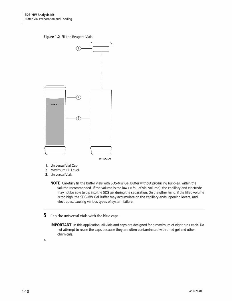
Figure 1.2 Fill the Reagent Vials
NOTE Carefully fill the buffer vials with SDS-MW Gel Buffer without producing bubbles, within the
volume recommended. If the volume is too low (< ½ of vial volume), the capillary and electrode
may not be able to dip into the SDS gel during the separation. On the other hand, if the filled volume
is too high, the SDS-MW Gel Buffer may accumulate on the capillary ends, opening levers, and
electrodes, causing various types of system failure.
5 Cap the universal vials with the blue caps.
IMPORTANT In this application, all vials and caps are designed for a maximum of eight runs each. Do
not attempt to reuse the caps because they are often contaminated with dried gel and other
chemicals.
1. Universal Vial Cap
2. Maximum Fill Level
3. Universal Vials
A51970AD1-10

SDS-MW Analysis Kit
Tray Configuration 1
Tray Configuration
1 Load the reagents into the system inlet (left) and outlet (right) 6x6 buffer trays using the
configuration illustrated in Table 1.3, Inlet Buffer Tray Configuration and Table 1.4, Outlet Buffer Tray Configuration.
2 Load the trays into the PA 800 plus system.
Inlet Buffer Tray
A1 to A6 – DDI H2O, use for dip step to clean capillary tip, 1.5 mL.
B4 to B6 – DDI H2O, use for dip step to clean capillary tip, 1.5 mL.
B1 to B3 – SDS-MW Buffer Gel (Gel-R) to fill capillary prior to each cycle, 1.2 mL.
C1 to C3 – SDS-MW Gel Buffer for separation (Gel-S), 1.1 mL.
D1 to D3 – 0.1N NaOH, use to precondition capillary, 1.5 mL.
E1 to E3 – 0.1N HCl, use to precondition capillary, 1.5 mL.
F1 to F3 – DDI H2O, use to precondition capillary, 1.5 mL.
Table 1.3 Inlet Buffer Tray Configuration
H2O
(Cycle 17-24)
H2O
(Cycle17-24)
H2O
(Cycle 9-16)
H2O
(Cycle 9-16)
H2O
(Cycle 1-8)
H2O
(Cycle 1-8)
H2O
(Cycle 17-24)
Gel-R
(Cycle 17-24)
Gel-S
(Cycle 17-24)
NaOH
(Cycle 17-24)
HCl
(Cycle 17-24)
H2O
(Cycle 17-24)
H2O
(Cycle 9-16)
Gel-R
(Cycle 9-16)
Gel-S
(Cycle 9-16)
NaOH
(Cycle 9-16)
HCl
(Cycle 9-16)
H2O
(Cycle 9-16)
H2O
(Cycle 1-8)
Gel-R
(Cycle 1-8)
Gel-S
(Cycle 1-8)
NaOH
(Cycle 1-8)
HCl
(Cycle 1-8)
H2O
(Cycle 1-8)
A B C D E F
A51970AD 1-11

SDS-MW Analysis Kit
Running the Assay
Outlet Buffer Tray
A1 to A6 – DDI H2O, use for dip step to clean capillary tip, 1.5 mL.
B4 to B6 – DDI H2O, use for dip step to clean capillary tip, 1.5 mL.
B1 to B3 – Waste vial for SDS-MW Gel rinse, 0.8 mL of DDI water.
C1 to C3 – SDS-MW Gel Buffer for separation (Gel-S), 1.1 mL.
D1 to D3 – Waste vial for 0.1N NaOH rinse, 0.8 ml of DDI water.
E1 to E3 – Waste vial for 0.1N HCl rinse, 0.8 ml of DDI water.
F1 to F3 – Waste vial for DDI H2O rinse, 0.8 ml of DDI water.
Running the Assay
Launching the SDS MW Instrument
1 Launch 32 Karat software. The Enterprise screen will display the available instruments.
2 Double-click on the SDS MW instrument to launch the SDS-MW assay.
Table 1.4 Outlet Buffer Tray Configuration
H2O
(Cycle 17-24)
H2O
(Cycle 17-24)
H2O
(Cycle 9-16)
H2O
(Cycle 9-16)
H2O
(Cycle 1-8)
H2O
(Cycle 1-8)
H2O
(Cycle 17-24)
Waste
(Cycle 17-24)
Gel-S
(Cycle 17-24)
Waste
(Cycle 17-24)
Waste
(Cycle 17-24)
Waste
(Cycle 17-24)
H2O
(Cycle 9-16)
Waste
(Cycle 9-16)
Gel-S
(Cycle 9-16)
Waste
(Cycle 9-16)
Waste
(Cycle 9-16)
Waste
(Cycle 9-16)
H2O
(Cycle 1-8)
Waste
(Cycle 1-8)
Gel-S
(Cycle 1-8)
Waste
(Cycle 1-8)
Waste
(Cycle 1-8)
Waste
(Cycle 1-8)
A B C D E F
A51970AD1-12

SDS-MW Analysis Kit
Running the Assay 1
3 Select SDS MW as the project on the log in screen.
NOTE Type in PA800 as the user name and type Plus as the password.
NOTE User Name and Password defaults have been established for installation and training purposes.
Conditioning a New Capillary
A new capillary needs to be conditioned once before use.
1 To initiate the conditioning method, select Control > Single Run from the 32 Karat Menu bar.
The Single Run Acquisition dialog box opens.
Figure 1.3 Single Run Acquisition Dialog Box
2 From the Method field, click on the Folder icon.
3 Select the SDS MW Conditioning - PA 800 plus.met file and specify the data filename of your choice.
4 Click on the Arrow button and select the Increment option.
A51970AD 1-13

SDS-MW Analysis Kit
Running SDS-MW Size Standard and Test Samples
5 Type 1 as the Number of Reps.
Since no sample will be injected, a vial injection position does not need to be specified.
6 Press Start to begin the conditioning process.
Running SDS-MW Size Standard and Test Samples
The sequence table is designed to automate the process of running size standard and samples. For your convenience a sequence template has been pre-programmed to run up to 24 unknown samples.
The sequence table has been designed this way to consider the automatic replacement of the assay reagents during the course of the experiment.
Once the buffer trays and samples have been loaded into the system, you are ready to begin the analysis of the test compounds.
NOTE Check the Beckman Coulter web site for the most current versions of pre-programmed sequences and
methods for this assay.
1 On the Task bar, select Control, then Sequence Run. The Run Sequence dialog box will open.
2 Select the Folder button to browse to the proper SDS MW sequence.
3 Set the Run Range to All.
4 Select Start.
A51970AD1-14

SDS-MW Analysis Kit
Running SDS-MW Size Standard and Test Samples 1
Figure 1.4 Run Sequence Dialog Box
An example of the sequence template pre-programming to run one conditioning run, 24 samples and molecular weight size standards, as well as a shutdown method is shown in Figure 1.5.
The shutdown method should be run at the end of the experimentation. This method cleans the capillary and turns off the UV lamp.
Figure 1.5 Sequence Table for SDS MW
A51970AD 1-15

SDS-MW Analysis Kit
Checking the Separation Results
Checking the Separation Results
The Protein Size Standard contains seven proteins (10, 20, 35, 50, 100, 150, and 225 kDa). All proteins should be completely separated within 30 minutes using our recommended method. See Figure 1.6 for a typical separation of the Size Standard.
Figure 1.6 Separation of Protein Molecular Weight Size Standard
Estimating Protein Molecular Weights
See Figure 1.7 for a typical calibration curve obtained by plotting the known molecular weight vs. migration time of each protein in the protein Size Standard. The molecular weight of an unknown protein can be estimated by using this calibration curve. The calculated molecular weights are displayed in the electropherogram by selecting Quality as an annotation.
It is recommended that this curve be re-calibrated every 24 cycles. This is done by running the Size Standard and updating the migration time values for each standard to reflect the new run. This update is performed in the qualitative analysis of the 32 Karat Control and Analysis Software. See Figure 1.7 below for an example of this set-up.
A51970AD1-16

SDS-MW Analysis Kit
Troubleshooting Guide 1
Figure 1.7 Qualitative Analysis Tab for Updating the Size Calibration Curve
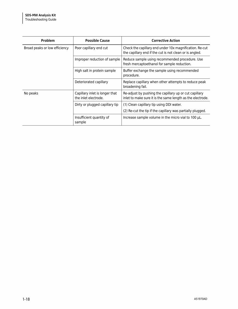
Troubleshooting Guide
Problem Possible Cause Corrective Action
Low or unsteady current Capillary Plugged (1) Rinse the capillary with DDI water at 100 psi for 10
minutes and then perform the capillary conditioning
method.
(2) If unsteady current still occurs after step (1), change
to a new capillary.
Air bubbles in the gel 1) Degas SDS-MW Gel Buffer under 5 to 15 Hg vacuum
for 5 minutes.
High current Contaminated Gel Buffer Replace gel buffer as needed
Contamination on electrode Clean electrodes. Consult the System Maintenance
Guide (A51964AD or current version).
Spikes in electropherogram Air bubbles in gel buffer 1) Degas SDS-MW Gel Buffer under 5 to 15 Hg vacuum
for 5 minutes.
A51970AD 1-17
SDS-MW Analysis Kit
Troubleshooting Guide
Broad peaks or low efficiency Poor capillary end cut Check the capillary end under 10x magnification. Re-cut
the capillary end if the cut is not clean or is angled.
Improper reduction of sample Reduce sample using recommended procedure. Use
fresh mercaptoethanol for sample reduction.
High salt in protein sample Buffer exchange the sample using recommended
procedure.
Deteriorated capillary Replace capillary when other attempts to reduce peak
broadening fail.
No peaks Capillary inlet is longer that
the inlet electrode.
Re-adjust by pushing the capillary up or cut capillary
inlet to make sure it is the same length as the electrode.
Dirty or plugged capillary tip (1) Clean capillary tip using DDI water.
(2) Re-cut the tip if the capillary was partially plugged.
Insufficient quantity of
sample
Increase sample volume in the micro vial to 100 µL.
Problem Possible Cause Corrective Action
A51970AD1-18

CHAPTER 2
Method Information
Instrument and Detector Initial Conditions
The instrument and detector initial conditions are the same for all SDS-MW methods.
Instrument Initial Conditions (All Methods)
Figure 2.1 Instrument Setup - Instrument Initial Conditions
A51970AD 2-1

Method Information
Instrument and Detector Initial Conditions
Detector Initial Conditions (All Methods)
Figure 2.2 Instrument Setup - PDA Detector
NOTE UV absorbance spectra across the entire separation will be obtained if acquisition is enabled on the
electropherogram scan data. This feature facilitates the identification of proteins and other UV absorbing
molecules.
Capillary Conditioning Method (SDS MW Conditioning - PA 800 plus.met)
A new capillary or a used capillary that has been stored for a long period of time must be conditioned using the Capillary Conditioning method before starting CE separation.
A51970AD2-2

Method Information
Instrument and Detector Initial Conditions 2
Figure 2.3 Time Program - Capillary Conditioning
SDS-MW Separation Method
Figure 2.4 SDS MW Separation - PA 800 plus.met
Shutdown Method
Figure 2.5 SDS MW Shutdown - PA 800 plus
A51970AD 2-3

© 2014 Beckman Coulter, Inc.
All Rights Reserved
www.beckmancoulter.com