
APPLICATION FOR SMALL WASTEWATER TREATMENT FACILITY - co.albany.wy.us form for septic... ·...
22
Albany County Planning Office 1002 S 3 RD Street, Laramie, WY 82070 Phone: (307) 721-2568 • Fax: (307) 721-2570 [email protected] www.co.albany.wy.us/planning.aspx APPLICATION FOR SMALL WASTEWATER TREATMENT FACILITY Requirements for Subject Property: Attached Application Form Complete Site Plan Permit from the City of Laramie if property is within the 201 IGA Planning Boundaries A copy of the deed, lease, or contract for deed as proof of ownership If the subject property is not adjacent to a public road, please include a copy of the easement granting you legal access to the property Applicable Fees ($325) THIS PERMIT APPLICATION MUST BE APPROVED PRIOR TO CONSTRUCTION: Please note that properties that lie within the 201 IGA planning boundary that are contiguous to existing or planned sewer lines must obtain a 201 IGA waiver from the review board. A LATE CHARGE OF $100.00 WILL BE ASSESSED FOR FILING THIS APPLICATION AFTER CONSTRUCTION HAS BEGUN PLEASE REVIEW CAREFULLY -- INCOMPLETE APPLICATIONS WILL BE RETURNED EXPIRATION DATE OF THIS PERMIT IS TWO YEARS FROM THE DATE OF APPLICATION APPROVAL BY THE REVIEWER. FEE The cost for all applications is $325.00 NOTE: An inspection of this site will be conducted prior to backfilling to determine if the septic system was installed according to the approved construction plans. Also, that the site characteristics are those indicated on the plans. This approval is not a guarantee of successful operation. SPECIAL WARNING! Field changes to the plan are common because of unanticipated problems. If changes are necessary, the installer must contact the Albany County Water and Wastewater Engineer to get approval for the changes. This is particularly true if the septic field must be dug deeper than called for on the plan. The property owner is responsible to see to it that this dialogue takes place. FOR OFFICE USE ONLY: WW-______-____ TYPE:____ CHECK #__________________ PIN # 05-________-____-__-____-_________.____ RECEIPT #_________________ ADDRESS: ________________________________ DATE RECEIVED____________ MAP REFERENCE: T-____ R-____ S-____ Q-____ ____ of ____
Transcript of APPLICATION FOR SMALL WASTEWATER TREATMENT FACILITY - co.albany.wy.us form for septic... ·...
Albany County Planning Office 1002 S 3RD Street, Laramie, WY 82070
Phone: (307) 721-2568 • Fax: (307) 721-2570
www.co.albany.wy.us/planning.aspx
APPLICATION FOR SMALL WASTEWATER TREATMENT FACILITY Requirements for Subject Property:
Attached Application Form Complete Site Plan Permit from the City of Laramie if property is within the 201 IGA Planning Boundaries A copy of the deed, lease, or contract for deed as proof of ownership If the subject property is not adjacent to a public road, please include a copy of the easement
granting you legal access to the property Applicable Fees ($325)
THIS PERMIT APPLICATION MUST BE APPROVED PRIOR TO CONSTRUCTION:
Please note that properties that lie within the 201 IGA planning boundary that are contiguous
to existing or planned sewer lines must obtain a 201 IGA waiver from the review board.
A LATE CHARGE OF $100.00 WILL BE ASSESSED FOR FILING THIS APPLICATION AFTER
CONSTRUCTION HAS BEGUN
PLEASE REVIEW CAREFULLY -- INCOMPLETE APPLICATIONS WILL BE RETURNED
EXPIRATION DATE OF THIS PERMIT IS TWO YEARS FROM THE DATE OF APPLICATION
APPROVAL BY THE REVIEWER.
FEE The cost for all applications is $325.00
NOTE: An inspection of this site will be conducted prior to backfilling to determine if the septic
system was installed according to the approved construction plans. Also, that the site characteristics
are those indicated on the plans. This approval is not a guarantee of successful operation.
SPECIAL WARNING! Field changes to the plan are common because of unanticipated
problems. If changes are necessary, the installer must contact the Albany County Water and
Wastewater Engineer to get approval for the changes. This is particularly true if the septic field must
be dug deeper than called for on the plan. The property owner is responsible to see to it that this
dialogue takes place.
FOR OFFICE USE ONLY:
WW-______-____ TYPE:____ CHECK #__________________ PIN # 05-________-____-__-____-_________.____ RECEIPT #_________________ ADDRESS: ________________________________ DATE RECEIVED____________ MAP REFERENCE: T-____ R-____ S-____ Q-____ ____ of ____

Application for Small Wastewater Treatment Facility Page 2 of 22
Owner of property___________________________________________Date__________________
Please provide an address where mail will reach you.
Your mailing address _______________________________________________________________
City_________________________________State_____________________Zip Code____________
Phone (Work) _______________ Phone (Home) __________________Phone (cell) _____________
Location of system site by county address______________________________________________
Name of Installer__________________________________________________________________
Note: Installer must be licensed in Albany County except if the installation is to be performed by the
owner of the property.
Installer’s Mail address _____________________________________________________________
City_________________________________State_____________________Zip Code____________
Phone (Work) _______________ Phone (Home) __________________Phone (cell) _____________
Right of Ingress/Applicant Certification
I hereby grant county-authorized personnel the right of ingress and egress from said lands for
any and all inspection purposes necessary to the exercise of this permit. I certify that, to the best of
my knowledge, the aforementioned information and material is true and correct, and I understand that
authorization of this permit does not guarantee successful operation.
THE OWNER OF RECORD MUST SIGN THIS APPLICATION. THE APPLICATION WILL NOT BE
ACCEPTED WITHOUT THE OWNER’S SIGNATURE! ALL SIGNATURES MUST BE LEGIBLE
Applicant’s Signature
Printed Name
Date
Consent of Owner of Record (if different from applicant)
Owner’s Signature
Printed Name
Date
Application for Small Wastewater Treatment Facility Page 3 of 22
INSTRUCTIONS
Using the results of the percolation test and soil examination, complete the following application form. The attached appendix provides information regarding techniques for soil testing. Be sure to complete all aspects of this application. Failure to do so could result in rejection of the application. Submit this application, along with the fee to the Albany County Planning Office. Once you receive approval from the County Water and Wastewater Engineer, you may begin the installation. After you have completed the installation BUT BEFORE BACKFILLING, contact the County Water and Wastewater Engineer for an inspection. Failure to do so could result in having to dig up the system for inspection and a late charge of $100.00.
Read the following pages before proceeding with filling out this application. In addition to obtaining this permit, you may have other city or county or DEQ requirements that must be met before you proceed, particularly if your property is in the Casper Aquifer Protection Zone or within the Intergovernmental 201 zone..
Regarding wastewater facilities in the Casper Aquifer Protection Zone: If your property lies
within the area designated as the Casper Aquifer Protection Zone (CAPZ), any septic field to be
installed in that area must be designed by a Professional Engineer or a Professional Geologist,
licensed to practice in Wyoming and qualified to do such work. An electrical engineer, for example,
may not have the requisite skills for this undertaking. The engineer/geologist should contact the
County Water and Wastewater Engineer for guidance regarding what will be expected. The County
Water and Wastewater Engineer will inspect the soil deep pits along with the site engineer where
engineered designs take place within the Casper Aquifer protection zone or the “201 Intergovern-
mental zone”..
Important!! Any of the recent subdivisions that have been approved within the CAPZ are required to
include a septic system that must be designed by a Professional Engineer and must include the
“Advantex “mode three” septic treatment system not the “mode one”.
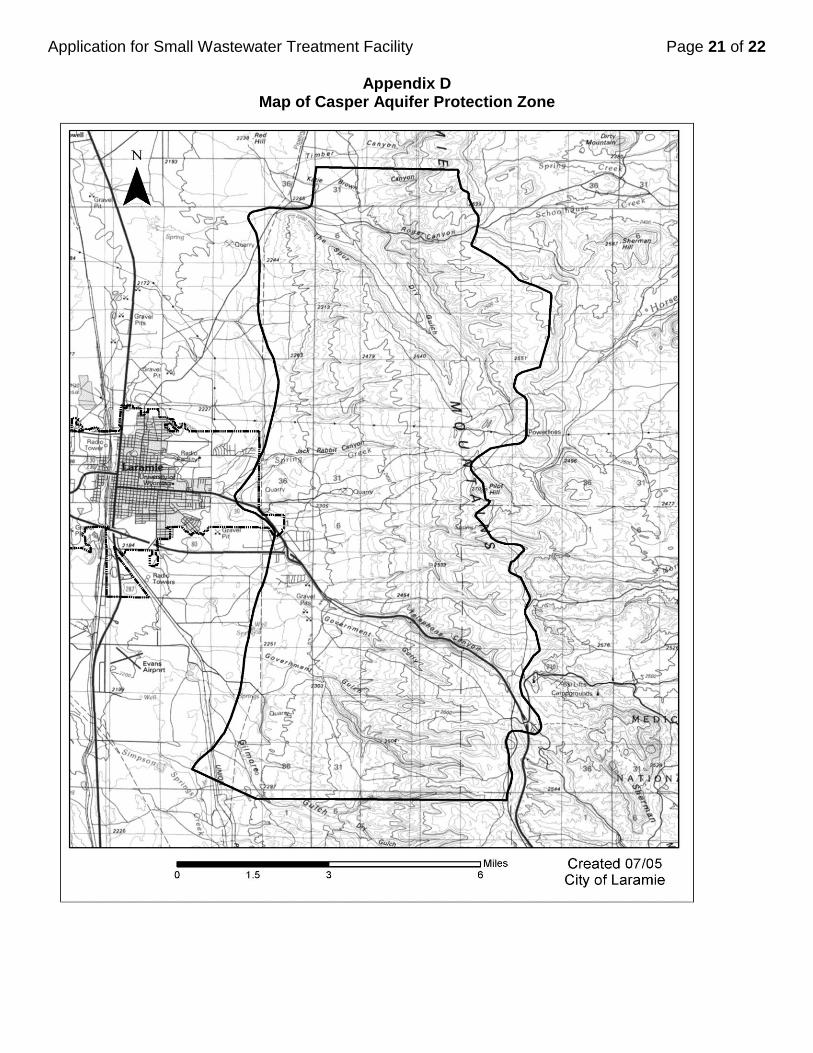
It is difficult to accurately plot the exact boundaries of the CAPZ. However, studies of the area show
that land east of Laramie to the summit of the Laramie Mountains and ranging approximately seven
miles to the north and six miles to the south of the city limits is very likely to be in the Casper Aquifer
Zone. Attached (page 21) is a map showing the general boundaries of the zone. If you suspect that
your property is in this zone, you should check with the Albany County Water and Wastewater
Engineer for verification before proceeding forward.
If your property lies west of Laramie or beyond seven miles north or beyond six miles south of the
city, you are unlikely to be within the zone and may proceed. The property owner is responsible for
clarification of this and all of the following topics.
Is the project to be built in the CAPZ? Yes No

Application for Small Wastewater Treatment Facility Page 4 of 22
201 IGA Planning Area: If your property is located within the “201 IGA Planning Area Boundary”
(shown on the map on page 22 of this form) of the Intergovernmental Agreement for Laramie
Wastewater Treatment Facilities and Collection Systems, you will need to secure a special permit to
install a septic field within that area. Until you have obtained that permit the Wastewater Engineer will
temporarily deny your application.
Is the project to be built in the 201 IGA Area? Yes No
Have you secured a permit to build a septic system in the 201 IGA planning area? Yes_________ No_________
Floodplain Permit If your septic system is to be located within a floodplain you are required to
obtain a Floodplain permit before constructing a structure or installing a septic system. Construction
of septic systems in floodplains will require a floodplain permit even if the structure (such as a house)
that is being served by the septic system is not in the floodplain. Septic fields that are positioned in
the floodplain must be well protected from the ravages of a flood. In the event that the structure or
some part of it is to be located in the floodplain, it will require that a floodplain construction permit be
secured from the Albany County Water and Wastewater Engineer.
Is the project to be built in a floodplain? Yes No
DESIGN OF THE SYSTEM 1. Type of construction (check one)
New System_______ Repair/Replacement_______
2. Source of Water Supply (check one)
Well______ Municipal supply______ Cistern______ Other______
If the source of water is “other” please describe.___________________________________
3. Topography of site (check one)
Flat_____ Gently sloped_____ Moderately sloped_____ Steeply sloped______
Will the site for the septic field be above or below the site for the residence (check one)?
Above__________ Below___________ Same elevation__________
Is a basement planned for this application? Yes ______ No______
Note: State code requires that the septic system be designed for two additional bedrooms if the
house will have a basement even if those bedrooms will not exist (see paragraph XX).
If any part of the plumbing within the house is more than three feet below the elevation of the
ground where the septic field will be located, you may have to provide a pump/ejector system.
Septic fields with trench bottoms that are more than five feet underground will not be allowed.
Application for Small Wastewater Treatment Facility Page 5 of 22
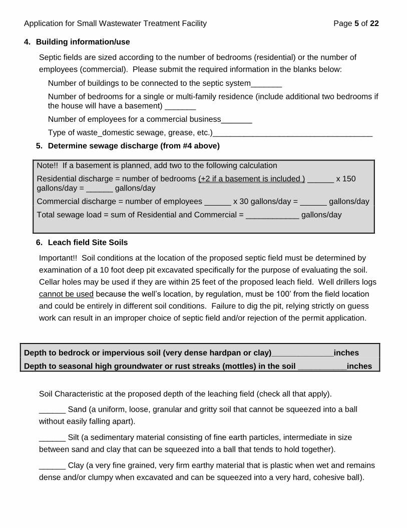
4. Building information/use
Septic fields are sized according to the number of bedrooms (residential) or the number of
employees (commercial). Please submit the required information in the blanks below:
Number of buildings to be connected to the septic system_______
Number of bedrooms for a single or multi-family residence (include additional two bedrooms if the house will have a basement) _______
Number of employees for a commercial business_______
Type of waste_domestic sewage, grease, etc.)____________________________________
5. Determine sewage discharge (from #4 above)
Note!! If a basement is planned, add two to the following calculation
Residential discharge = number of bedrooms (+2 if a basement is included ) ______ x 150 gallons/day = ______ gallons/day
Commercial discharge = number of employees ______ x 30 gallons/day = ______ gallons/day
Total sewage load = sum of Residential and Commercial = ____________ gallons/day
6. Leach field Site Soils
Important!! Soil conditions at the location of the proposed septic field must be determined by
examination of a 10 foot deep pit excavated specifically for the purpose of evaluating the soil.
Cellar holes may be used if they are within 25 feet of the proposed leach field. Well drillers logs
cannot be used because the well’s location, by regulation, must be 100’ from the field location
and could be entirely in different soil conditions. Failure to dig the pit, relying strictly on guess
work can result in an improper choice of septic field and/or rejection of the permit application.
Depth to bedrock or impervious soil (very dense hardpan or clay)______________inches
Depth to seasonal high groundwater or rust streaks (mottles) in the soil ___________inches
Soil Characteristic at the proposed depth of the leaching field (check all that apply).
______ Sand (a uniform, loose, granular and gritty soil that cannot be squeezed into a ball
without easily falling apart).
______ Silt (a sedimentary material consisting of fine earth particles, intermediate in size
between sand and clay that can be squeezed into a ball that tends to hold together).
______ Clay (a very fine grained, very firm earthy material that is plastic when wet and remains
dense and/or clumpy when excavated and can be squeezed into a very hard, cohesive ball).
Application for Small Wastewater Treatment Facility Page 6 of 22
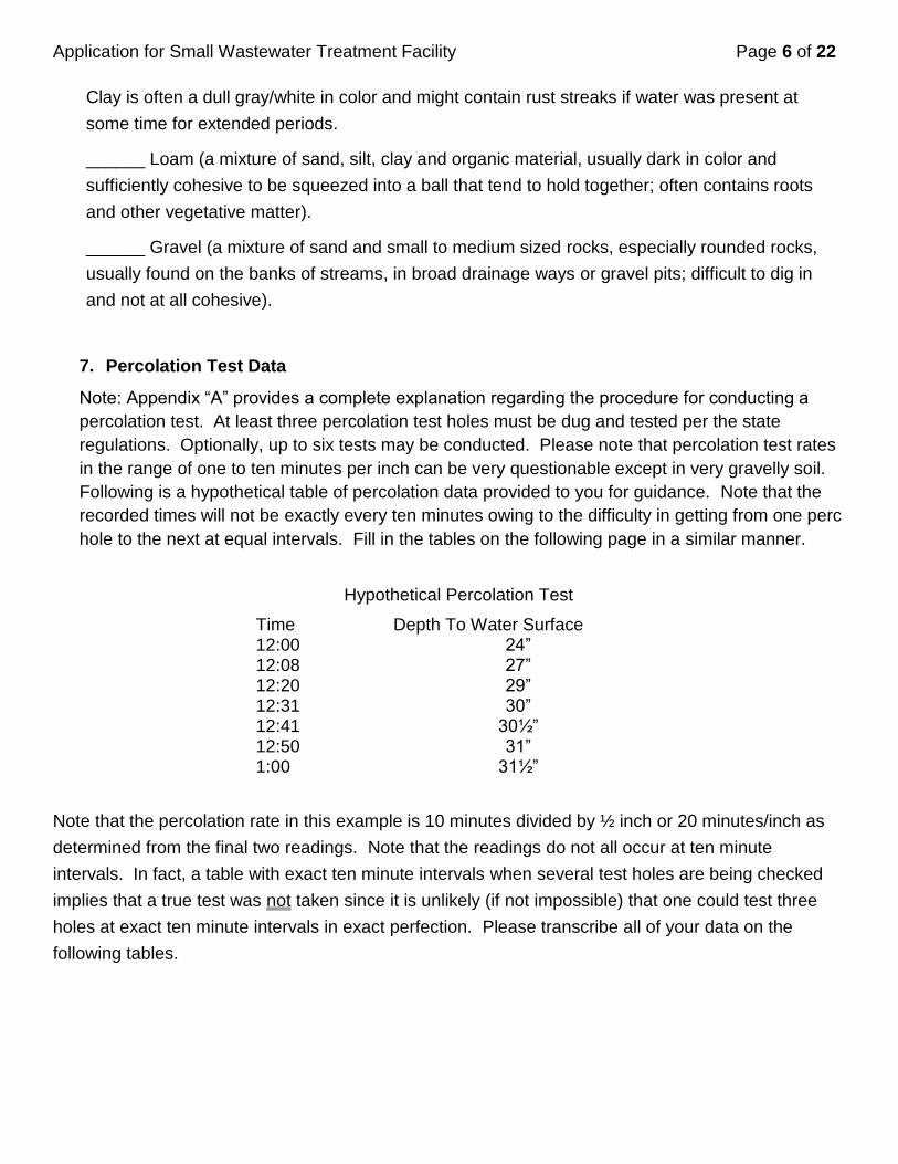
Clay is often a dull gray/white in color and might contain rust streaks if water was present at
some time for extended periods.
______ Loam (a mixture of sand, silt, clay and organic material, usually dark in color and
sufficiently cohesive to be squeezed into a ball that tend to hold together; often contains roots
and other vegetative matter).
______ Gravel (a mixture of sand and small to medium sized rocks, especially rounded rocks,
usually found on the banks of streams, in broad drainage ways or gravel pits; difficult to dig in
and not at all cohesive).
7. Percolation Test Data
Note: Appendix “A” provides a complete explanation regarding the procedure for conducting a
percolation test. At least three percolation test holes must be dug and tested per the state
regulations. Optionally, up to six tests may be conducted. Please note that percolation test rates
in the range of one to ten minutes per inch can be very questionable except in very gravelly soil.
Following is a hypothetical table of percolation data provided to you for guidance. Note that the
recorded times will not be exactly every ten minutes owing to the difficulty in getting from one perc
hole to the next at equal intervals. Fill in the tables on the following page in a similar manner.
Hypothetical Percolation Test
Time Depth To Water Surface 12:00 24” 12:08 27” 12:20 29” 12:31 30” 12:41 30½” 12:50 31” 1:00 31½”
Note that the percolation rate in this example is 10 minutes divided by ½ inch or 20 minutes/inch as
determined from the final two readings. Note that the readings do not all occur at ten minute
intervals. In fact, a table with exact ten minute intervals when several test holes are being checked
implies that a true test was not taken since it is unlikely (if not impossible) that one could test three
holes at exact ten minute intervals in exact perfection. Please transcribe all of your data on the
following tables.

Application for Small Wastewater Treatment Facility Page 7 of 22
Time Depth to Water Surface
Time Depth to Water Surface
Hole #1 Hole #2
Hole #3 Hole #4
Hole #5 Hole #6
Summary
Perc #1 = ______min/inch Perc #2 = ______min/inch Perc #3 = ______min/inch
Perc #4 = ______min/inch Perc #5 = ______min/inch Perc #6 = ______min/inch
A: If you have conducted three tests, provide the slowest percolation rate______ min/inch
Or
B: If you have conducted six tests, provide the average percolation rate _______ min/inch
8. Septic Tank Information
Note: This application assumes that the septic tank will be obtained from a county-approved
commercial manufacturer. Commercial septic tanks may be constructed from reinforced
concrete or plastic. If you plan to construct your own tank, discuss this with the County Water
and Wastewater Engineer. Septic tanks must have two compartments as required by county
code. Some manufacturers do not provide two compartments and must not be used.
Application for Small Wastewater Treatment Facility Page 8 of 22
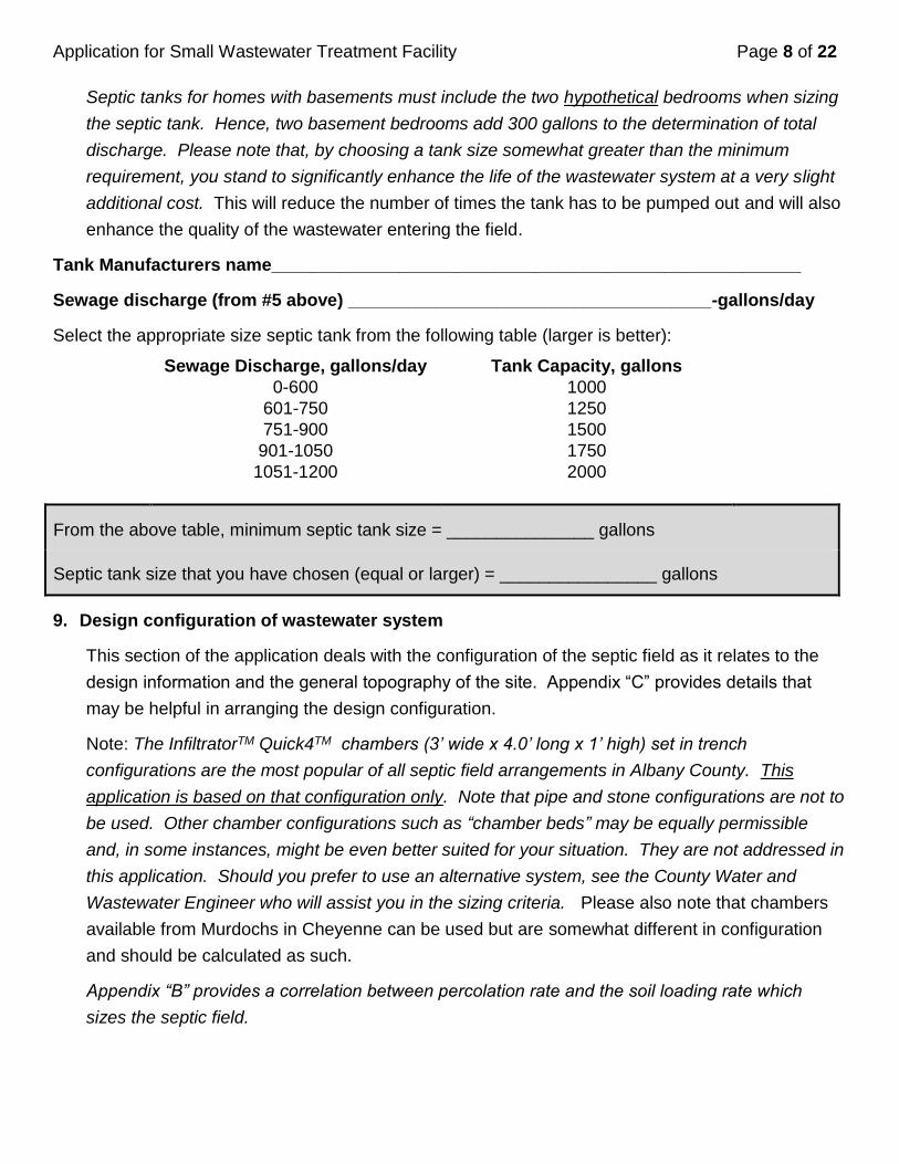
Septic tanks for homes with basements must include the two hypothetical bedrooms when sizing
the septic tank. Hence, two basement bedrooms add 300 gallons to the determination of total
discharge. Please note that, by choosing a tank size somewhat greater than the minimum
requirement, you stand to significantly enhance the life of the wastewater system at a very slight
additional cost. This will reduce the number of times the tank has to be pumped out and will also
enhance the quality of the wastewater entering the field.
Tank Manufacturers name______________________________________________________
Sewage discharge (from #5 above) _____________________________________-gallons/day
Select the appropriate size septic tank from the following table (larger is better):
Sewage Discharge, gallons/day Tank Capacity, gallons
0-600 1000
601-750 1250
751-900 1500
901-1050 1750
1051-1200 2000
From the above table, minimum septic tank size = _______________ gallons
Septic tank size that you have chosen (equal or larger) = ________________ gallons
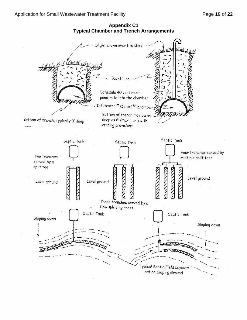
9. Design configuration of wastewater system
This section of the application deals with the configuration of the septic field as it relates to the
design information and the general topography of the site. Appendix “C” provides details that
may be helpful in arranging the design configuration.
Note: The InfiltratorTM Quick4TM chambers (3’ wide x 4.0’ long x 1’ high) set in trench
configurations are the most popular of all septic field arrangements in Albany County. This
application is based on that configuration only. Note that pipe and stone configurations are not to
be used. Other chamber configurations such as “chamber beds” may be equally permissible
and, in some instances, might be even better suited for your situation. They are not addressed in
this application. Should you prefer to use an alternative system, see the County Water and
Wastewater Engineer who will assist you in the sizing criteria. Please also note that chambers
available from Murdochs in Cheyenne can be used but are somewhat different in configuration
and should be calculated as such.
Appendix “B” provides a correlation between percolation rate and the soil loading rate which
sizes the septic field.
Application for Small Wastewater Treatment Facility Page 9 of 22
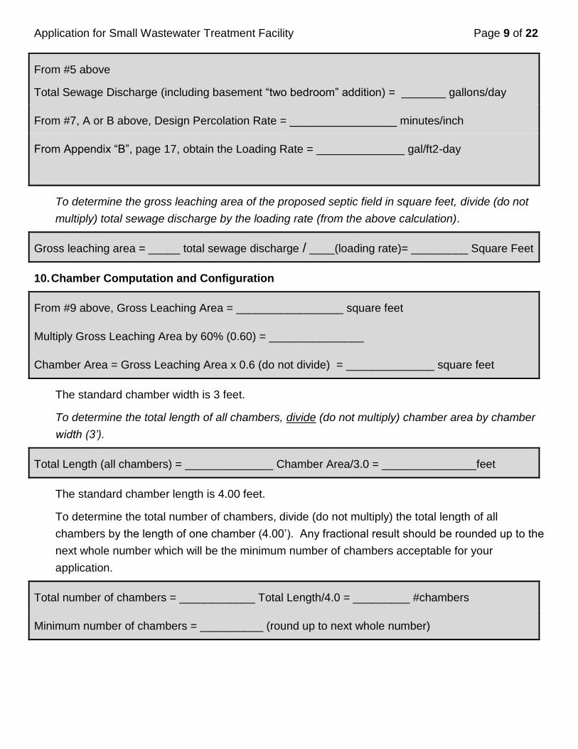
From #5 above
Total Sewage Discharge (including basement “two bedroom” addition) = _______ gallons/day
From #7, A or B above, Design Percolation Rate = _________________ minutes/inch
From Appendix “B”, page 17, obtain the Loading Rate = ______________ gal/ft2-day
To determine the gross leaching area of the proposed septic field in square feet, divide (do not
multiply) total sewage discharge by the loading rate (from the above calculation).
Gross leaching area = _____ total sewage discharge / ____(loading rate)= _________ Square Feet
10. Chamber Computation and Configuration
From #9 above, Gross Leaching Area = _________________ square feet
Multiply Gross Leaching Area by 60% (0.60) = _______________
Chamber Area = Gross Leaching Area x 0.6 (do not divide) = ______________ square feet
The standard chamber width is 3 feet.
To determine the total length of all chambers, divide (do not multiply) chamber area by chamber
width (3’).
Total Length (all chambers) = ______________ Chamber Area/3.0 = _______________feet
The standard chamber length is 4.00 feet.
To determine the total number of chambers, divide (do not multiply) the total length of all
chambers by the length of one chamber (4.00’). Any fractional result should be rounded up to the
next whole number which will be the minimum number of chambers acceptable for your
application.
Total number of chambers = ____________ Total Length/4.0 = _________ #chambers
Minimum number of chambers = __________ (round up to next whole number)
Application for Small Wastewater Treatment Facility Page 10 of 22
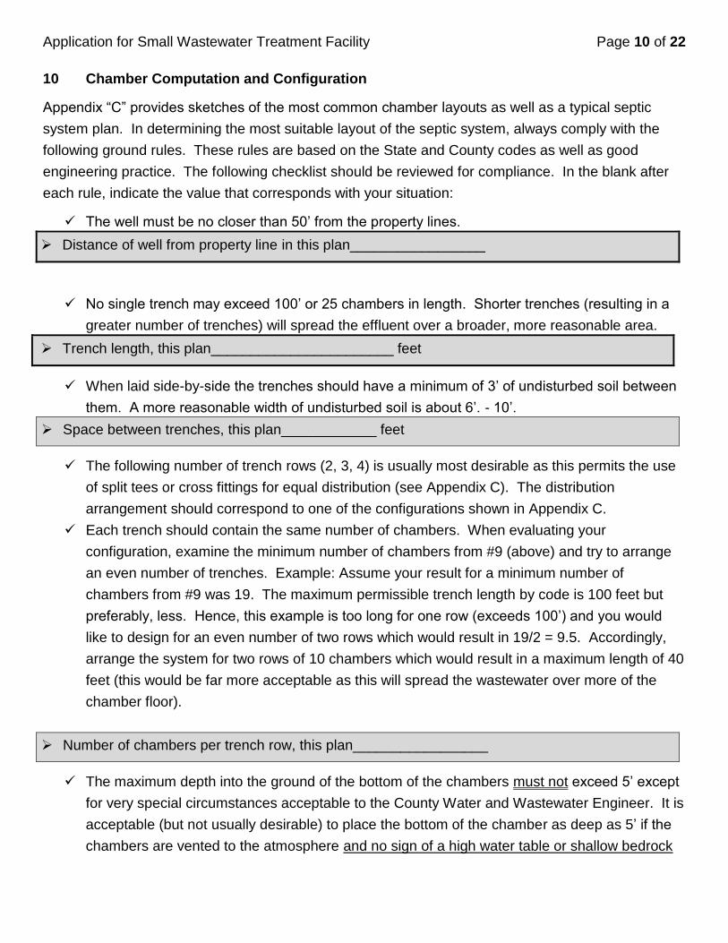
10 Chamber Computation and Configuration
Appendix “C” provides sketches of the most common chamber layouts as well as a typical septic
system plan. In determining the most suitable layout of the septic system, always comply with the
following ground rules. These rules are based on the State and County codes as well as good
engineering practice. The following checklist should be reviewed for compliance. In the blank after
each rule, indicate the value that corresponds with your situation:
The well must be no closer than 50’ from the property lines.
Distance of well from property line in this plan_________________
No single trench may exceed 100’ or 25 chambers in length. Shorter trenches (resulting in a
greater number of trenches) will spread the effluent over a broader, more reasonable area.
Trench length, this plan_______________________ feet
When laid side-by-side the trenches should have a minimum of 3’ of undisturbed soil between
them. A more reasonable width of undisturbed soil is about 6’. - 10’.
Space between trenches, this plan____________ feet
The following number of trench rows (2, 3, 4) is usually most desirable as this permits the use
of split tees or cross fittings for equal distribution (see Appendix C). The distribution
arrangement should correspond to one of the configurations shown in Appendix C.
Each trench should contain the same number of chambers. When evaluating your
configuration, examine the minimum number of chambers from #9 (above) and try to arrange
an even number of trenches. Example: Assume your result for a minimum number of
chambers from #9 was 19. The maximum permissible trench length by code is 100 feet but
preferably, less. Hence, this example is too long for one row (exceeds 100’) and you would
like to design for an even number of two rows which would result in 19/2 = 9.5. Accordingly,
arrange the system for two rows of 10 chambers which would result in a maximum length of 40
feet (this would be far more acceptable as this will spread the wastewater over more of the
chamber floor).
Number of chambers per trench row, this plan_________________
The maximum depth into the ground of the bottom of the chambers must not exceed 5’ except
for very special circumstances acceptable to the County Water and Wastewater Engineer. It is
acceptable (but not usually desirable) to place the bottom of the chamber as deep as 5’ if the
chambers are vented to the atmosphere and no sign of a high water table or shallow bedrock
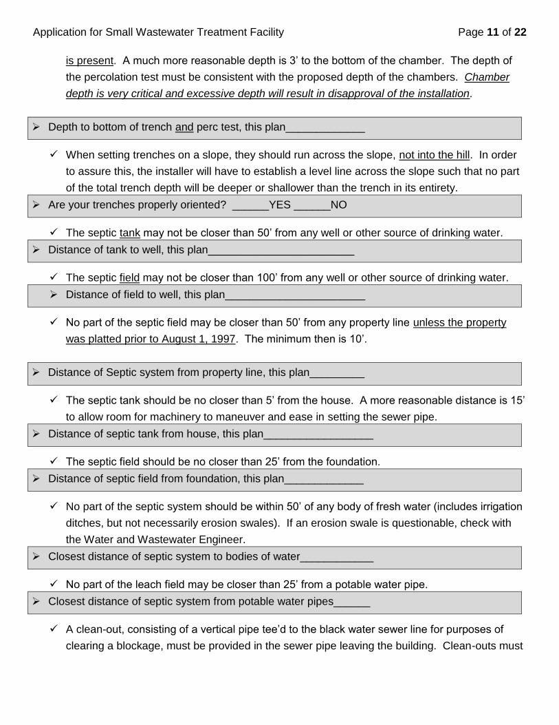
Application for Small Wastewater Treatment Facility Page 11 of 22
is present. A much more reasonable depth is 3’ to the bottom of the chamber. The depth of
the percolation test must be consistent with the proposed depth of the chambers. Chamber
depth is very critical and excessive depth will result in disapproval of the installation.
Depth to bottom of trench and perc test, this plan_____________
When setting trenches on a slope, they should run across the slope, not into the hill. In order
to assure this, the installer will have to establish a level line across the slope such that no part
of the total trench depth will be deeper or shallower than the trench in its entirety.
Are your trenches properly oriented? ______YES ______NO
The septic tank may not be closer than 50’ from any well or other source of drinking water.
Distance of tank to well, this plan________________________
The septic field may not be closer than 100’ from any well or other source of drinking water.
Distance of field to well, this plan_______________________
No part of the septic field may be closer than 50’ from any property line unless the property
was platted prior to August 1, 1997. The minimum then is 10’.
Distance of Septic system from property line, this plan_________
The septic tank should be no closer than 5’ from the house. A more reasonable distance is 15’
to allow room for machinery to maneuver and ease in setting the sewer pipe.
Distance of septic tank from house, this plan__________________
The septic field should be no closer than 25’ from the foundation.
Distance of septic field from foundation, this plan_____________
No part of the septic system should be within 50’ of any body of fresh water (includes irrigation
ditches, but not necessarily erosion swales). If an erosion swale is questionable, check with
the Water and Wastewater Engineer.
Closest distance of septic system to bodies of water____________
No part of the leach field may be closer than 25’ from a potable water pipe.
Closest distance of septic system from potable water pipes______
A clean-out, consisting of a vertical pipe tee’d to the black water sewer line for purposes of
clearing a blockage, must be provided in the sewer pipe leaving the building. Clean-outs must
Application for Small Wastewater Treatment Facility Page 12 of 22
also be provided wherever the sewer pipe has a significant break in alignment, where two
sewer pipes come together and/or at least every 100’ from building to tank. It is obviously best
to minimize the length of the sewer pipe.
Have you provided the required clean-outs? _____YES _____NO
All sewer pipe leading from the building to the septic tank and from the tank to firm ground
must be schedule 40 and must be laid at a slope between 1/8” and 1/4” per foot. Where the
ground is steeper than ¼” per foot, 45 degree drops shall be placed to allow for the correct
pipe slope where necessary.
Have you provided for pipe gauge and slope? _____YES _____NO
A capped access port leading from the septic tank discharge pipe to the surface of the ground
should be provided to allow access to the leach field after the tank. This will allow the insertion
of leaching chemicals into the field (not the tank) in the event of future leaching problems.
Have you provided an access port? ______YES ______NO
In order to avoid deep septic fields you may need to provide a sewage pump within a separate
chamber (or a lift station in the basement). If you are going to provide a pump, it must have
sufficient capacity to pump 10 gallons per minute to the septic field.
Will you be providing a pump system? ______YES ______NO
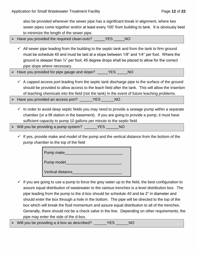
If yes, provide make and model of the pump and the vertical distance from the bottom of the
pump chamber to the top of the field
Pump make___________________________
Pump model__________________________
Vertical distance_______________________
If you are going to use a pump to force the grey water up to the field, the best configuration to
assure equal distribution of wastewater to the various trenches is a level distribution box. The
pipe leading from the pump to the d-box should be schedule 40 and be 2” in diameter and
should enter the box through a hole in the bottom. The pipe will be directed to the top of the
box which will break the fluid momentum and assure equal distribution to all of the trenches.
Generally, there should not be a check valve in the line. Depending on other requirements, the
pipe may enter the side of the d-box.
Will you be providing a d-box as described? ______YES ______NO
Application for Small Wastewater Treatment Facility Page 13 of 22
There should be sufficient space in your plan to replace the septic field with one of equal
dimensions.
Have you provided a replacement area? ______YES ______NO
Water softeners are particularly injurious to septic fields. If a water softener is contemplated,
the salt brine should be very limited and/or directed to a different leaching facility. Discuss this
with the County Water and Wastewater Engineer.
Do you intend to use a water softener? ______YES ______NO
Modern heating systems increase the available amount of heat through the lowering of the
stack gas discharge temperature. This results in condensate which is often disposed of by
directing it into the sewer line. If the sewer line is less than three feet below grade, this may
cause freezing/blockage of the sewer pipe during the winter.
Will sewer pipe be at least 3’ below grade where it leaves the house? ______YES ______NO
A relatively recent development in the design of wastewater systems is a septic tank discharge
filter. This filter is located in the tank discharge baffle and filters out much of the lint and other
clogging materials leaving the tank. The filter will absolutely enhance and increase the life of
the leaching field. This filter is required in Albany County. The downside is that the filter will
eventually become clogged and must be “hosed off” every year or so. This procedure of
“hosing off” the filter simply calls for reaching into the tank, removing the filter and cleaning it
off with running water. While a relatively simple job, and one that will enhance the life of the
leaching field (the most expensive part of the system), this process is not particularly palatable
and is not for everybody. Septic tank pumpers can do this service at the same time they pump
out the tank.
Have you arranged for professional servicing of the discharge filter? ______YES ______NO
If “NO” you are stating that you will take responsibility for this action yourself.

Application for Small Wastewater Treatment Facility Page 14 of 22
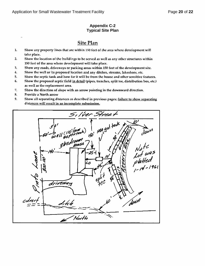
11. Description of proposed septic system 1. Show all appropriate dimensions as called for in Section 10, above.
2. Show any property lines that are within 150 feet of the area where development will take place.
3. Show the location of the buildings to be served as well as any other structures within 150 feet of the
area where development will take place.
4. Show any roads, driveways or parking areas within 150 feet of development site.
5. Show the well or its proposed location and any ditches, streams, lakeshore, etc.
6. Show septic tank and how far it will be from the house and the wells and other sensitive features.
7. Show the proposed septic field in detail (pipes, trenches, split tee, distribution box, etc.) as well as the
replacement area.
8. Show distances of well to all extremes of the septic field.
9. Show the direction of slope with an arrow pointing in the downward direction.
10. Provide a North arrow
11. Show all separating distances as described in previous pages; failure to show separating distances will
result in an incomplete submission.
Please be neat. Sloppy sketches that cannot be evaluated will be returned for changes for clarity.

Application for Small Wastewater Treatment Facility Page 15 of 22
12. Site Location/Directions In order that the inspection can be carried out in a timely and orderly fashion, the Water and Wastewater Engineer needs a set of accurate directions and/or maps to get to your site. Starting with the intersection of two well-known roads, provide directions and/or a map that accurately indicates how to get to your site. Clarity is important as, otherwise, we may not be able to find your site.
Application for Small Wastewater Treatment Facility Page 16 of 22
Appendix A
Percolation Test Procedure
Follow these instructions and use the attached sketch for reference.
1. Dig a perc hole using a spade or post hole digger. The 6” – 12” diameter perc hole should be
at a depth corresponding to that of the proposed septic field. Do not use a motorized auger as
this often results in a compaction of the soil which will yield a slower than normal perc.
2. Fill the hole to the top with clean water. Be careful of using paint buckets or other
contaminated vessels as this also might cause an unusual perc rate.
3. Let the water soak in until the next day. When you come back, the hole should be empty. If
not, assuming 12 hours or more have passed, the soil in this particular location may be
unsuitable and you should look to a different location.
4. Assuming the hole is empty, refill it with clean water to a depth of at least 12”.
5. Measure the elevation of the water as a function of time, usually every five or ten minutes for a
full hour or until the hole empties out.
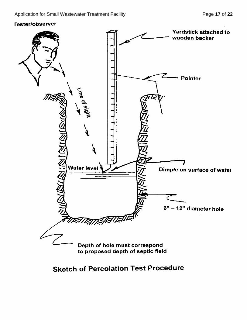
6. A good measuring device is a yard stick attached to a wooden stick with a finishing nail as a
pointer driven into the end. A piece of coat hanger inserted in the ground next to the hole
makes a good point of reference to read the depth from the surface of the ground. As you
lower the stick down into the hole look for the nail to dimple the water surface and read off the
point of reference at that instant. The attached sketch depicts this procedure.
7. At the end of an hour of taking data you should find that the rate of drop of the water should be
very consistent. If you look at your data you will probably find that the rate of drop is going to
be very fast at the beginning but will have slowed to a near constant rate by the time that you
arrive at the end of the hour.
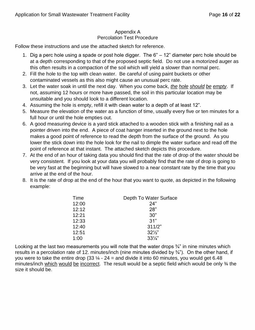
8. It is the rate of drop at the end of the hour that you want to quote, as depicted in the following
example:
Time Depth To Water Surface 12:00 24” 12:12 28” 12:21 30” 12:33 31” 12:40 311/2” 12:51 32½” 1:00 33¼”
Looking at the last two measurements you will note that the water drops ¾” in nine minutes which results in a percolation rate of 12. minutes/inch (nine minutes divided by ¾”). On the other hand, if you were to take the entire drop (33 ¼ - 24 = and divide it into 60 minutes, you would get 6.48 minutes/inch which would be incorrect. The result would be a septic field which would be only ¾ the size it should be.
Application for Small Wastewater Treatment Facility Page 17 of 22

Application for Small Wastewater Treatment Facility Page 18 of 22
Appendix B Loading Rate Table
Percolation Rate Loading Rate Percolation Rate
Percolation Rate (minutes/inches)
Loading Rate (Gal/ft2-day)
Less than 6 mpi - - - - - Cannot use this generic procedure*
31 32 33 34
0.39 0.385 0.38 0.375
35 0.37 6 0.75 36 0.365 7 0.71 37 0.36 8 0.68 38 0.357 9 0.65 39 0.353
10 0.62 40 0.35 11 0.60 41 0.347 12 0.58 42 0.343 13 0.56 43 0.34 14 0.54 44 0.337 15 0.52 45 0.333 16 0.505 46 0.33 17 0.49 47 0.327 18 0.48 48 0.325 19 0.47 49 0.323 20 0.46 50 0.32 21 0.45 51 0.318 22 0.44 52 0.316 23 0.435 53 0.314 24 0.43 54 0.312 25 0.42 55 0.31 26 0.415 56 0.308 27 0.41 57 0.306 28 0.405 58 0.304 29 0.40 59 0.302 30 0.395 60 0.30
More than 60 mpi Cannot use this Generic Procedure
*Note: If the percolation rate for your site is less than 6 minutes/inch or greater than 60 minutes/inch, you cannot use this generic procedure. You must hire a Wyoming Registered Professional Engineer and submit an application customized for your specific site conditions.
Application for Small Wastewater Treatment Facility Page 19 of 22
Appendix C1 Typical Chamber and Trench Arrangements
Application for Small Wastewater Treatment Facility Page 20 of 22
Appendix C-2
Typical Site Plan
Application for Small Wastewater Treatment Facility Page 21 of 22
Appendix D Map of Casper Aquifer Protection Zone
Application for Small Wastewater Treatment Facility Page 22 of 22
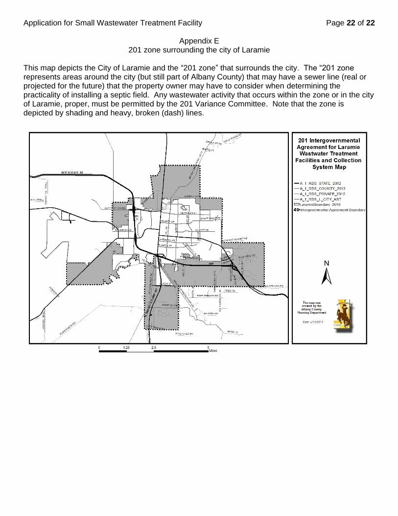
Appendix E 201 zone surrounding the city of Laramie
This map depicts the City of Laramie and the “201 zone” that surrounds the city. The “201 zone represents areas around the city (but still part of Albany County) that may have a sewer line (real or projected for the future) that the property owner may have to consider when determining the practicality of installing a septic field. Any wastewater activity that occurs within the zone or in the city of Laramie, proper, must be permitted by the 201 Variance Committee. Note that the zone is depicted by shading and heavy, broken (dash) lines.