Application Example 11/2015 Protective Door with Spring ... · Application Example 11/2015...
43
https://support.industry.siemens.com/cs/ww/de/view/21063946 Application Example 11/2015 Protective Door with Spring- loaded Interlocking with an S7-1500 SIMATIC Safety Integrated
-
Upload
truongkhue -
Category
Documents
-
view
258 -
download
3
Transcript of Application Example 11/2015 Protective Door with Spring ... · Application Example 11/2015...

https://support.industry.siemens.com/cs/ww/de/view/21063946
Application Example 11/2015
Protective Door with Spring-loaded Interlocking with an S7-1500 SIMATIC Safety Integrated

Warranty and Liability
Protective door with spring-loaded interlocking with an S7-1500 Entry ID: 21063946, V3.0, 11/2015 2
S
iem
en
s A
G 2
01
5 A
ll ri
gh
ts r
ese
rve
d
Warranty and Liability
Note The Application Examples are not binding and do not claim to be complete with regard to configuration, equipment or any contingencies. The Application Examples do not represent customer-specific solutions. They are only intended to provide support for typical applications. You are responsible for the correct operation of the described products. These Application Examples do not relieve you of the responsibility of safely and professionally using, installing, operating and servicing equipment. When using these Application Examples, you recognize that we cannot be made liable for any damage/claims beyond the liability clause described. We reserve the right to make changes to these Application Examples at any time and without prior notice. If there are any deviations between the recommendations provided in this Application Example and other Siemens publications – e.g. Catalogs – the contents of the other documents shall have priority.
We do not accept any liability for the information contained in this document.
Any claims against us – based on whatever legal reason – resulting from the use of the examples, information, programs, engineering and performance data etc., described in this Application Example shall be excluded. Such an exclusion shall not apply in the case of mandatory liability, e.g. under the German Product Liability Act (“Produkthaftungsgesetz”), in case of intent, gross negligence, or injury of life, body or health, guarantee for the quality of a product, fraudulent concealment of a deficiency or breach of fundamental contractual obligations (“wesentliche Vertragspflichten”). The compensation for damages due to a breach of a fundamental contractual obligation is, however, limited to the foreseeable damage, typical for the type of contract, except in the event of intent or gross negligence or injury to life, body or health. The above provisions do not imply a change of the burden of proof to your detriment.
Any form of duplication or distribution of these Application Examples or excerpts hereof is prohibited without the expressed consent of Siemens AG.
Security informa-
tion
Siemens provides products and solutions with industrial security functions that support the secure operation of plants, solutions, machines, equipment and/or networks. They are important components in a holistic industrial security concept. With this in mind, Siemens’ products and solutions undergo continuous development. Siemens recommends strongly that you regularly check for product updates.
For the secure operation of Siemens products and solutions, it is necessary to take suitable preventive action (e.g. cell protection concept) and integrate each component into a holistic, state-of-the-art industrial security concept. Third-party products that may be in use should also be considered. For more information about industrial security, visit http://www.siemens.com/industrialsecurity.
To stay informed about product updates as they occur, sign up for a product-specific newsletter. For more information, visit https://support.industry.siemens.com.

Table of Contents
Protective door with spring-loaded interlocking with an S7-1500 Entry ID: 21063946, V3.0, 11/2015 3
S
iem
en
s A
G 2
01
5 A
ll ri
gh
ts r
ese
rve
d
Table of Contents Warranty and Liability ................................................................................................. 2
1 Task ..................................................................................................................... 5
2 Solution............................................................................................................... 6
2.1 Overview............................................................................................... 6 2.2 Description of the core functionality ..................................................... 7 2.2.1 Monitoring the position of the protective door ...................................... 7 2.2.2 Interlocking function of the protective door .......................................... 7 2.2.3 Advantages .......................................................................................... 8 2.2.4 Assumed knowledge ............................................................................ 8 2.3 Hardware and software components ................................................... 9
3 Basics ............................................................................................................... 11
3.1 Basic terms ......................................................................................... 11 3.2 Functional safety ................................................................................ 11 3.3 Guards ................................................................................................ 12 3.3.1 Important requirements for position switches..................................... 12 3.3.2 Series connection of position switches .............................................. 12 3.3.3 Interlocking of protective doors .......................................................... 13
4 Mode of Operation ........................................................................................... 14
4.1 Position switch functionality with interlocking ..................................... 14 4.2 Standard user program functionality .................................................. 15 4.3 Functionality of the safety program .................................................... 16 4.3.1 Overview............................................................................................. 16 4.3.2 Program details on the ProtDoorWithInterlocking function block ....... 17
Monitoring the position of the protective door .................................... 20 Release and monitoring of the interlocking ........................................ 20 Controlling and monitoring the actuators ........................................... 22
4.3.3 Reintegration of passivated channels ................................................ 23 4.4 Data exchange between standard user program and safety
program .............................................................................................. 23
5 Configuration and Settings............................................................................. 24
5.1 F-DI configuration ............................................................................... 24 5.2 F-DQ configuration ............................................................................. 26
6 Installation and Commissioning .................................................................... 28
6.1 Installing the hardware ....................................................................... 28 6.2 Commissioning ................................................................................... 29 6.2.1 Preparation ......................................................................................... 29 6.2.2 Loading the S7 project into CPU S7-1516F ....................................... 29 6.2.3 Assigning a device name ................................................................... 31 6.2.4 Assigning F target address................................................................. 32
7 Operating the Application ............................................................................... 34
7.1 Starting the machine .......................................................................... 34 7.2 Opening the protective door ............................................................... 34 7.3 Acknowledging a discrepancy fault .................................................... 34 7.4 Acknowledge other faults of the safety function ................................. 35
8 Evaluation of the Safety Function .................................................................. 36
8.1 Standards ........................................................................................... 36 8.2 Safety functions .................................................................................. 36 8.3 Evaluation in accordance with IEC 62061.......................................... 37

Table of Contents
Protective door with spring-loaded interlocking with an S7-1500 Entry ID: 21063946, V3.0, 11/2015 4
S
iem
en
s A
G 2
01
5 A
ll ri
gh
ts r
ese
rve
d
8.3.1 Evaluation of “Detecting” .................................................................... 37 8.3.2 Evaluation of “Evaluating” .................................................................. 37 8.3.3 Evaluation of “Reacting” ..................................................................... 37 8.3.4 Result of the evaluation in accordance with IEC 62061 ..................... 39 8.4 Evaluation in accordance with ISO 13849-1 ...................................... 40 8.4.1 Evaluation of “Detecting” .................................................................... 40 8.4.2 Evaluation of “Evaluating” .................................................................. 40 8.4.3 Evaluation of “Reacting” ..................................................................... 41 8.4.4 Result of the evaluation in accordance with ISO 13849-1 ................. 42
9 Links & Literature ............................................................................................ 43
10 History............................................................................................................... 43

1 Task
2.1 Overview
Protective door with spring-loaded interlocking with an S7-1500 Entry ID: 21063946, V3.0, 11/2015 5
S
iem
en
s A
G 2
01
5 A
ll ri
gh
ts r
ese
rve
d
1 Task To prevent access to the hazard zone of a machine during operation, it shall be fitted with a protective door. Since overrunning machine components may cause hazards, the protective door must be kept closed, and it must only be possible to open it after the machine is in standstill. It shall only be possible to start the machine after the protective door has been closed and locked. In the case of a fault, the machine shall be shut down safely.
Figure 1-1
The risk analysis of the machine shows that monitoring the position of the protective door must be designed up to SIL 3 in accordance with IEC 62061, or PL e in accordance with EN ISO 13849-1.
The interlocking function of the protective door has to be designed up to SIL 2 in accordance with IEC 62061, or PL d in accordance with EN ISO 13849-1.
Table 1-1
Safety function Description Requirement
SF1 The protective door is kept closed until the machine has stopped.
SIL 2 or PL d
SF2 If the protective door is opened, the machine must be switched off safely.
SIL 3 or PL e

2 Solution
2.1 Overview
Protective door with spring-loaded interlocking with an S7-1500 Entry ID: 21063946, V3.0, 11/2015 6
S
iem
en
s A
G 2
01
5 A
ll ri
gh
ts r
ese
rve
d
2 Solution
2.1 Overview
The figure below shows a schematic overview of the most important components of the solution:
Figure 2-1
M
Start
Stopp
Quittieren
Entriegeln
1 2
3
Start
Stop
Acknowledge
Unlock

2 Solution
2.2 Description of the core functionality
Protective door with spring-loaded interlocking with an S7-1500 Entry ID: 21063946, V3.0, 11/2015 7
S
iem
en
s A
G 2
01
5 A
ll ri
gh
ts r
ese
rve
d
2.2 Description of the core functionality
In this application example two safety functions are discussed:
Monitoring the position of the protective door
Interlocking function of the protective door
2.2.1 Monitoring the position of the protective door
Detecting
Monitoring the position of the protective door (SF2) is performed via two position switches SIRIUS 3SE5 (Figure 2-1, positions 1 & 2) to reach the demanded safety level. If one position switch fails, an opened protective door is still detected by the second position switch. A failed position switch is detected by the discrepancy monitoring in the controller, and switching it back on is prevented until the failure has been removed.
Position switches with different functions are used to counter common cause failures. For position switch 1, the position of the protective door is detected by means of a separate actuator that engages the position switch when closing the position switch. Position switch 2 has a swiveling lever that is actuated when the protective door is open. In both position switches, one NC contact each is evaluated and connected to the fail-safe inputs of the ET 200SP (see Figure 6-1 Wiring diagram). Cross-circuits between the two signals of the position switches are detected by the failsafe input module.
Evaluating
In order to guarantee the seamless integration of the safety function into the automation process, a SIMATIC S7-1500 fail-safe controller is used in which standard user program and safety program run next to each other. The inputs and outputs are read in and output by the distributed I/O ET 200SP. The controller and the distributed I/O communicate via the fail-safe PROFIsafe PROFINET profile.
Reaction
To achieve SIL 3 in accordance with IEC 62061, or PL e in accordance with ISO 13849-1, double channel switch off is performed. Two SIRIUS 3RT2 contactors (Figure 2-1, position 3) are used, and their correct function is monitored via the auxiliary contacts of the contactors through the fail-safe controller.
If one of both contactors welds, the second contactor continues to ensure a safe shut-down. Welding of a contactor is detected at the next signal change, and renewed switching on is prevented until the failure has been removed.
2.2.2 Interlocking function of the protective door
The position switch with position 1 (see Figure 2-1) is a position switch with interlocking. Apart from monitoring the position of the protective door, the door can be kept closed during operation and hence entry into the hazard zone be prevented (SF1).
To be able to switch on the machine, the protective door must be closed and locked. Unlocking the protective door is only possible at the end of a configured period of time, after the machine has been switched off, so the operator is protected against hazardous machine overrun motion.
2 Solution
2.2 Description of the core functionality
Protective door with spring-loaded interlocking with an S7-1500 Entry ID: 21063946, V3.0, 11/2015 8
S
iem
en
s A
G 2
01
5 A
ll ri
gh
ts r
ese
rve
d
According to the standard EN ISO 14119 “Safety of machinery – Interlocking devices associated with guards – Principles for design and selection” the required SIL or PLr of the interlocking function is usually lower than that of the position monitoring of the protective door. Based on the risk assessment, the interlocking function in this example is designed up to SIL 2 or PL d. The evaluation of the safety function is performed in chapter 8.
2.2.3 Advantages
Minimal wiring expenses by using fail-safe S7-CPU and distributed I/O. The significance of this advantage increases with the increase in realized safety functions.
Programming the safety program with engineering tools integrated in TIA Portal.
Only one fail-safe S7-CPU is required since standard user program and safety program run on a coexistent basis in the S7-CPU.
2.2.4 Assumed knowledge
The following knowledge is assumed:
Basics of functional safety
Basic knowledge of STEP 7 programming
Basic knowledge of fail-safe automation systems
2 Solution
2.3 Hardware and software components
Protective door with spring-loaded interlocking with an S7-1500 Entry ID: 21063946, V3.0, 11/2015 9
S
iem
en
s A
G 2
01
5 A
ll ri
gh
ts r
ese
rve
d
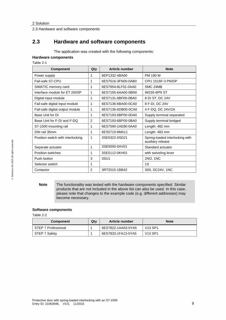
2.3 Hardware and software components
The application was created with the following components:
Hardware components
Table 2-1
Component Qty Article number Note
Power supply 1 6EP1332-4BA00 PM 190 W
Fail-safe S7-CPU 1 6ES7516-3FN00-0AB0 CPU 1516F-3 PN/DP
SIMATIC memory card 1 6ES7954-8LF01-0AA0 SMC 24MB
Interface module for ET 200SP 1 6ES7155-6AA00-0BN0 IM155-6PN ST
Digital input module 1 6ES7131-6BF00-0BA0 8 DI ST, DC 24V
Fail-safe digital input module 1 6ES7136-6BA00-0CA0 8 F-DI, DC 24V
Fail-safe digital output module 1 6ES7136-6DB00-0CA0 4 F-DQ, DC 24V/2A
Base Unit for DI 1 6ES7193-6BP00-0DA0 Supply terminal separated
Base Unit for F-DI and F-DQ 2 6ES7193-6BP00-0BA0 Supply terminal bridged
S7-1500 mounting rail 1 6ES7590-1AE80-0AA0 Length: 482 mm
DIN rail 35mm 1 6ES5710-8MA11 Length: 483 mm
Position switch with interlocking 1 3SE5322-0SD21 Spring-loaded interlocking with auxiliary release
Separate actuator 1 3SE5000-0AV01 Standard actuator
Position switches 1 3SE5112-0KH01 with swiveling lever
Push button 3 3SU1 2NO, 1NC
Selector switch 1 1S
Contactor 2 3RT2015-1BB42 S00, DC24V, 1NC
Note The functionality was tested with the hardware components specified. Similar products that are not included in the above list can also be used. In this case, please note that changes to the example code (e.g. different addresses) may become necessary.
Software components
Table 2-2
Component Qty Article number Note
STEP 7 Professional 1 6ES7822-1AA03-0YA5 V13 SP1
STEP 7 Safety 1 6ES7833-1FA13-0YA5 V13 SP1

2 Solution
2.3 Hardware and software components
Protective door with spring-loaded interlocking with an S7-1500 Entry ID: 21063946, V3.0, 11/2015 10
S
iem
en
s A
G 2
01
5 A
ll ri
gh
ts r
ese
rve
d
Example files and projects
The following list includes all files and projects that are used in this example.
Table 2-3
Component Note
21063946_Protective_door_with_spring_interlocking_DOC_V30_en.pdf This document
21063946_Protective_door_with_spring_interlocking_CODE_V30.zip This zip file contains the STEP 7 project.
21063946_Protective_door_with_spring_interlocking_SET_V30.set Evaluation of the safety functions as SET project

3 Basics
3.1 Basic terms
Protective door with spring-loaded interlocking with an S7-1500 Entry ID: 21063946, V3.0, 11/2015 11
S
iem
en
s A
G 2
01
5 A
ll ri
gh
ts r
ese
rve
d
3 Basics
3.1 Basic terms
Cross-circuit
The cross-circuit detection is a diagnostic function of an evaluation device, as a result of which short-circuits or cross-circuits are detected between the two input channels (sensor circuits).
A cross-circuit can occur, for example, if a plastic-sheathed cable is crushed. Without cross-circuit detection this would lead to a situation, for example, where a 2-channel emergency stop circuit does not trigger a shut-down, even if only one NC contact is faulty (secondary fault).
Feedback circuit
A feedback circuit is used for the monitoring of controlled actuators (e.g. relay or contactors) with positively driven contacts or mirror contacts. The outputs can only be enabled when the feedback circuit is closed. When using a redundant switch off path, the feedback circuit of both actuators has to be evaluated. For this purpose, they may also be connected in series.
Positive opening operation
Positive opening switches are designed in a way that the operation of the switch inevitably leads to an opening of the contacts. Welded contacts are forced open through the operation (EN 60947-5-1).
Positively driven contacts
For a component with positively driven contacts it is guaranteed that the NC and NO contacts are never closed at the same time (EN 60947-5-1).
3.2 Functional safety
From the view of the goods to be protected, safety is indivisible. However, since the causes of the hazards and therefore also the technical measures for avoiding them may be very different, the types of safety are also distinguished, for example, by specifying the respective cause of possible hazards. For this reason it is referred to “electrical safety” when hazards from electricity are expressed or “functional safety” when the safety depends on the correct function.
In order to achieve functional safety of a machine or plant, it is necessary for the safety-relevant parts of the protective equipment and control devices to function correctly and that they behave in a way that the plant stays in a safe state or is brought to a safe state in the event of a fault.
A very high-quality technology is necessary to achieve this, where the requirements described in the appropriate standards are met. The requirements to achieve functional safety are based on the following basic targets:
Avoidance of systematic faults
Control of systematic faults
Managing accidental faults or failures

3 Basics
3.3 Guards
Protective door with spring-loaded interlocking with an S7-1500 Entry ID: 21063946, V3.0, 11/2015 12
S
iem
en
s A
G 2
01
5 A
ll ri
gh
ts r
ese
rve
d
The measure for the functional safety achieved, is the probability of dangerous failures, the fault tolerance and the quality through which the freedom from systematic faults is to be guaranteed. This expressed in the standards through different terms:
In IEC 62061: “Safety Integrity Level” (SIL)
In ISO 13849-1: “Performance Level” (PL)
More information on functional safety can be found in \3\.
3.3 Guards
The solution used most in the area of plants and machinery is securing hazard zones with mechanical guards or access hatches. Here, unauthorized access to plant sections must be monitored and hazardous machine functions be prevented when the guard is not closed. Principles for design and selection of interlocking devices associated with guards are available in EN ISO 14119.
The guard can be monitored via mechanical position or safety switches as well as by using contactless safety switches on a magnetic or RFID basis.
3.3.1 Important requirements for position switches
Position switches must be positioned so they are not damaged when approached or passed. Therefore, they must not be used as mechanical stop.
Only sensors with positively opening contacts must be used.
Protected sensor cables must be installed.
Only normally closed contacts, or a combination of NC and NO contacts of the position switches are used safety-relevant evaluation.
Automatic restart of the machine after closing the protective door is only permitted if it can be ensured that nobody has entered the hazard zone before the protective door is closed (for example, for maintenance hatches, protective covers).
It is recommended to use position switches with different function principles (e.g. with separate actuating and swiveling lever) to counter common cause failures (CCF).
NOTICE This list is not a complete list of requirements for position switches.
3.3.2 Series connection of position switches
Position switches up to PL d (according to ISO 13849-1) or SIL 2 (in accordance with IEC 62061) may only be connected in series if it can be ensured that several

3 Basics
3.3 Guards
Protective door with spring-loaded interlocking with an S7-1500 Entry ID: 21063946, V3.0, 11/2015 13
S
iem
en
s A
G 2
01
5 A
ll ri
gh
ts r
ese
rve
d
protective doors are not regularly opened simultaneously (since otherwise, fault detection cannot be performed).
Series connection in PL e (in accordance with ISO 13849-1) or SIL 3 (in accordance with IEC 62061) is not possible.
Figure 3-1
Schutztür 1
Schutztür 2
3.3.3 Interlocking of protective doors
Often, protective door interlocking is also realized in combination with protective door monitoring. Interlocking devices are used for securing hazard zones from unauthorized access. Mostly for two reasons:
1. Protecting humans from dangerous machine overrun, high temperatures, etc. by making the hazard zone accessible only after the dangerous machine motion has stopped.
2. Interlocking may be useful from a process safety point of view. This applies if the hazard is stopped after opening the guard, yet damage to machine or workpiece might result. The machine is first moved to a proper stop position before enabling access.
Protective door 1
Protective door 2

4 Mode of Operation
4.1 Position switch functionality with interlocking
Protective door with spring-loaded interlocking with an S7-1500 Entry ID: 21063946, V3.0, 11/2015 14
S
iem
en
s A
G 2
01
5 A
ll ri
gh
ts r
ese
rve
d
4 Mode of Operation
4.1 Position switch functionality with interlocking
An actuator installed at the protective door engages a form-fit mounted safety position switch with interlocking. The SIRIUS 3SE5 position switch with interlocking used here uses a spring-loaded interlocking device and works according to the closed-current principle. That is, in the zero potential state, the door is interlocked and only disengaged after voltage is applied.
If the door is closed and no voltage is applied, a locking mechanism engages the separate actuator and hence prevents the door from being opened. When applying voltage, the locking mechanism disengages the separate actuator by means of a magnet, and the interlocking is unlocked.
Figure 4-1
Engaging and disengaging the interlocking is controlled via a fail-safe output of the ET 200SP. An NC contact in the position switch is used by the controller for monitoring the position of the locking mechanism and comparing it with the control command. The normally closed contact is closed if the protective door is interlocked.
The SIRIUS 3SE5 position switches are equipped with a mechanical fail-locking system that prevents the door from interlocking unless it is closed.
4 Mode of Operation
4.2 Standard user program functionality
Protective door with spring-loaded interlocking with an S7-1500 Entry ID: 21063946, V3.0, 11/2015 15
S
iem
en
s A
G 2
01
5 A
ll ri
gh
ts r
ese
rve
d
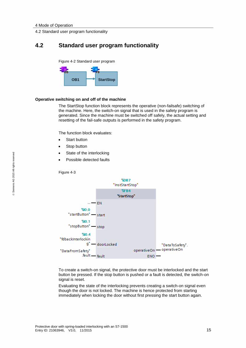
4.2 Standard user program functionality
Figure 4-2 Standard user program
OB1 StartStop
Operative switching on and off of the machine
The StartStop function block represents the operative (non-failsafe) switching of the machine. Here, the switch-on signal that is used in the safety program is generated. Since the machine must be switched off safely, the actual setting and resetting of the fail-safe outputs is performed in the safety program.
The function block evaluates:
Start button
Stop button
State of the interlocking
Possible detected faults
Figure 4-3
To create a switch-on signal, the protective door must be interlocked and the start button be pressed. If the stop button is pushed or a fault is detected, the switch-on signal is reset.
Evaluating the state of the interlocking prevents creating a switch-on signal even though the door is not locked. The machine is hence protected from starting immediately when locking the door without first pressing the start button again.
4 Mode of Operation
4.3 Functionality of the safety program
Protective door with spring-loaded interlocking with an S7-1500 Entry ID: 21063946, V3.0, 11/2015 16
S
iem
en
s A
G 2
01
5 A
ll ri
gh
ts r
ese
rve
d
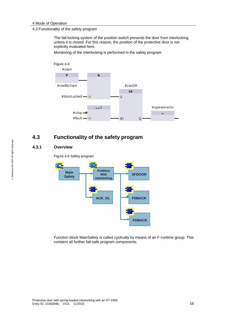
The fail-locking system of the position switch prevents the door from interlocking unless it is closed. For this reason, the position of the protective door is not explicitly evaluated here.
Monitoring of the interlocking is performed in the safety program.
Figure 4-4
4.3 Functionality of the safety program
4.3.1 Overview
Figure 4-5 Safety program
ProtDoor
With
Interlocking
ACK_GL
FDBACK
FDBACK
SFDOORMain
Safety
Function block MainSafety is called cyclically by means of an F-runtime group. This contains all further fail-safe program components.

4 Mode of Operation
4.3 Functionality of the safety program
Protective door with spring-loaded interlocking with an S7-1500 Entry ID: 21063946, V3.0, 11/2015 17
S
iem
en
s A
G 2
01
5 A
ll ri
gh
ts r
ese
rve
d
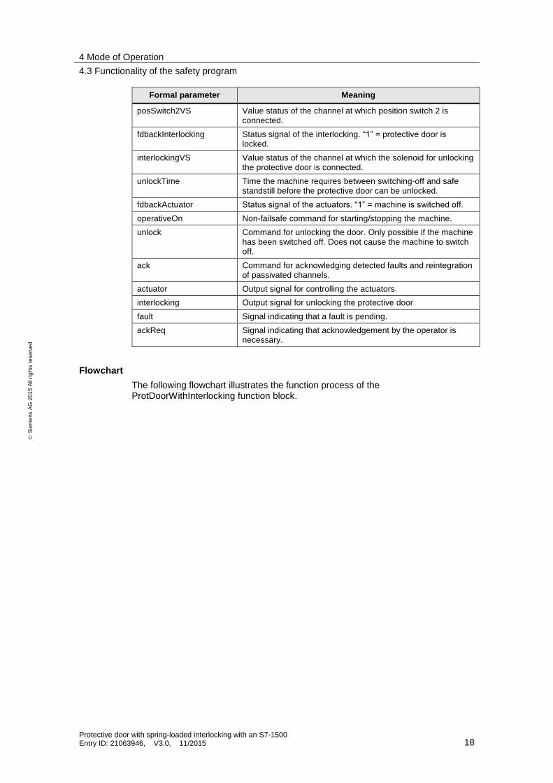
4.3.2 Program details on the ProtDoorWithInterlocking function block
Function block ProtDoorWithInterlocking realizes monitoring the position of the protective door, unlocking and monitoring of the interlocking, as well as controlling and monitoring of the actuators.
Figure 4-6
Table 4-1
Formal parameter Meaning
posSwitch1 Signal of position switch 1. “1” = door is closed.
posSwitch2 Signal of position switch 2. “1” = door is closed.
posSwitch1VS Value status of the channel at which position switch 1 is connected.
4 Mode of Operation
4.3 Functionality of the safety program
Protective door with spring-loaded interlocking with an S7-1500 Entry ID: 21063946, V3.0, 11/2015 18
S
iem
en
s A
G 2
01
5 A
ll ri
gh
ts r
ese
rve
d
Formal parameter Meaning
posSwitch2VS Value status of the channel at which position switch 2 is connected.
fdbackInterlocking Status signal of the interlocking. “1” = protective door is locked.
interlockingVS Value status of the channel at which the solenoid for unlocking the protective door is connected.
unlockTime Time the machine requires between switching-off and safe standstill before the protective door can be unlocked.
fdbackActuator Status signal of the actuators. “1” = machine is switched off.
operativeOn Non-failsafe command for starting/stopping the machine.
unlock Command for unlocking the door. Only possible if the machine has been switched off. Does not cause the machine to switch off.
ack Command for acknowledging detected faults and reintegration of passivated channels.
actuator Output signal for controlling the actuators.
interlocking Output signal for unlocking the protective door
fault Signal indicating that a fault is pending.
ackReq Signal indicating that acknowledgement by the operator is necessary.
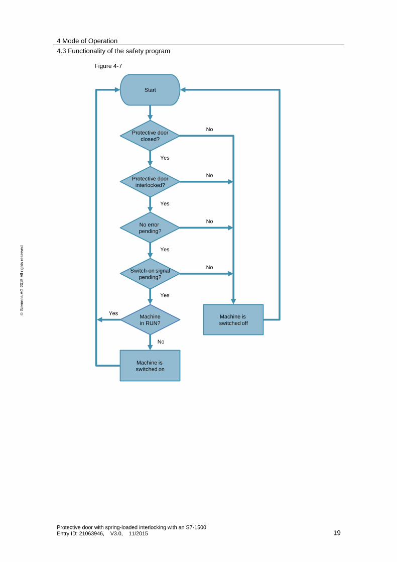
Flowchart
The following flowchart illustrates the function process of the ProtDoorWithInterlocking function block.
4 Mode of Operation
4.3 Functionality of the safety program
Protective door with spring-loaded interlocking with an S7-1500 Entry ID: 21063946, V3.0, 11/2015 19
S
iem
en
s A
G 2
01
5 A
ll ri
gh
ts r
ese
rve
d
Figure 4-7
No error
pending?
Protective door
interlocked?
Machine
in RUN?
Protective door
closed?
Switch-on signal
pending?
Yes
Machine is
switched on
Machine is
switched off
Yes
Yes
Yes
Yes
No
No
No
No
No
Start

4 Mode of Operation
4.3 Functionality of the safety program
Protective door with spring-loaded interlocking with an S7-1500 Entry ID: 21063946, V3.0, 11/2015 20
S
iem
en
s A
G 2
01
5 A
ll ri
gh
ts r
ese
rve
d
Monitoring the position of the protective door
The SFDOOR instruction contained in STEP 7 Safety is used here. Both inputs IN1 and IN2 are monitored for discrepancy so wire break is detected immediately, and a failure of both position switches (e.g. a dropped off position switch) is detected at the latest during the next opening of the protective door.
Figure 4-8
In this application example, acknowledgement after opening the protective door is not necessary, since the protective door can only be opened after the machine has been switched off.
Release and monitoring of the interlocking
The door is unlocked under the following conditions:
The actuators switched off (“1” signal at #fdbackActuator).
The configured time after switching off the actuators has elapsed.
The command for unlocking is pending (“1” signal at #unlock).
The door is locked again under the following conditions:
The protective door is closed (“1” signal at #statDoorClosed).
The command for unlocking is not pending (“0” signal at #unlock).

4 Mode of Operation
4.3 Functionality of the safety program
Protective door with spring-loaded interlocking with an S7-1500 Entry ID: 21063946, V3.0, 11/2015 21
S
iem
en
s A
G 2
01
5 A
ll ri
gh
ts r
ese
rve
d
Figure 4-9
Disengaging and monitoring the interlocking is performed using the FDBACK instruction contained in STEP 7 Safety. If “1” is pending at input ON, output Q switched on. Within the configured FDB_TIME time, the signal at the FEEDBACK input must be switched inverse to output signal Q. Otherwise, Q is switched off and a fault displayed at output ERROR. Afterwards, the fault must be acknowledged via input ACK. It is output via the ACK_REQ output that an acknowledgement is required.
Figure 4-10
A contact in the position switch (#fdbackInterlocking) is used for monitoring whether the interlocking switches correctly. In the event of a fault, the protective door is locked and the machine is switched off safely.

4 Mode of Operation
4.3 Functionality of the safety program
Protective door with spring-loaded interlocking with an S7-1500 Entry ID: 21063946, V3.0, 11/2015 22
S
iem
en
s A
G 2
01
5 A
ll ri
gh
ts r
ese
rve
d
Note In the newer controllers S7-1200 and S7-1500, the channel granular QBAD bit is replaced by the value status. The following rules apply for the value status:
FALSE: Substitute values are output.
TRUE: Process values are output.
The value status behaves inversely to the QBAD bit and is entered into the process image of the inputs (PII).
For more information on the value status, please refer to \5\.
Controlling and monitoring the actuators
The FDBACK instruction contained in STEP 7 Safety is used here. If “1” is pending at input ON, output Q switched on. Within the configured FDB_TIME time, the signal at the FEEDBACK input must be switched inverse to output signal Q. Otherwise, Q is switched off and a fault displayed at output ERROR. Afterwards, the fault must be acknowledged via input ACK. It is output via the ACK_REQ output that an acknowledgement is required.
Figure 4-11
The following requirements must be met for switching the machine on:
The protective door must be closed.
The protective door must be interlocked.
The operative switch-on signal must be pending.
No fault must be pending in the feedback circuit monitoring of the interlocking (in the event of a fault, the protective door is interlocked).
Further instructions
Furthermore, all signals of the used instructions, stating that a fault is pending or that acknowledgement by the user is necessary, are collected in function block ProtDoorWithInterlocking and written to output #fault and output #ackReq.

4 Mode of Operation
4.4 Data exchange between standard user program and safety program
Protective door with spring-loaded interlocking with an S7-1500 Entry ID: 21063946, V3.0, 11/2015 23
S
iem
en
s A
G 2
01
5 A
ll ri
gh
ts r
ese
rve
d
4.3.3 Reintegration of passivated channels
The ACK_GL instruction contained in STEP 7 Safety is used here. It generates an acknowledgement for the simultaneous reintegration of all F-I/Os/channels of the F periphery of an F-runtime group after communication faults or F-I/O/channel faults.
Figure 4-12
Examples of events that cause passivation:
Wire break on the F-DQ
Missing power supply at the F-DI
Note If a fault occurs in the hardware (e.g. due to wire break), it may take several seconds, depending on the fault type, until the module detects that the fault has been removed. Only then will acknowledgement take effect.
4.4 Data exchange between standard user program and safety program
In order to exchange data between the standard user program and the safety program, two global data blocks are used:
DataToSafety
DataFromSafety
The DataToSafety data block is written by the standard user program and read by the safety program. Data block DataFromSafety is read by the standard user program and written by the safety program.
Note For more information about the data exchange between the standard user program and the safety program, please refer to \5\.

5 Configuration and Settings
5.1 F-DI configuration
Protective door with spring-loaded interlocking with an S7-1500 Entry ID: 21063946, V3.0, 11/2015 24
S
iem
en
s A
G 2
01
5 A
ll ri
gh
ts r
ese
rve
d
5 Configuration and Settings The enclosed project does not require any further configuration. If you want to replicate the application example with other components, then the most important settings are shown in this chapter.
NOTICE The settings shown below contribute to meeting the required safety level. Changes on the settings may cause loss of the safety function.
5.1 F-DI configuration
Behavior after channel fault
In the event of channel faults, only the affected channel is passivated and not the entire module.
Figure 5-1 Behavior in the event of a channel fault
Short circuit test
The short-circuit test of the used channels has been activated.
Figure 5-2 Activating the short-circuit test

5 Configuration and Settings
5.1 F-DI configuration
Protective door with spring-loaded interlocking with an S7-1500 Entry ID: 21063946, V3.0, 11/2015 25
S
iem
en
s A
G 2
01
5 A
ll ri
gh
ts r
ese
rve
d
Channel parameters
Monitoring the position of the protective door is performed via channel pair 0, 4. The evaluation of the encoders must be set to “1oo1 evaluation” since the discrepancy evaluation is performed in function block SFDOOR.
Figure 5-3 Evaluation of the encoders
Since both position switches are often attached at different locations of the protective door (e.g. hinge switch) they might not trip simultaneously. Therefore, a high discrepancy time is required.
Evaluating discrepancies through the hardware is therefore not suitable since discrepancies are permitted as long as they do not exceed the set discrepancy time.
For discrepancy monitoring through function block SFDOOR the discrepancy time is infinite; however, any discrepancy is detected as a fault.
The table below discusses the differences when evaluating discrepancies:

5 Configuration and Settings
5.2 F-DQ configuration
Protective door with spring-loaded interlocking with an S7-1500 Entry ID: 21063946, V3.0, 11/2015 26
S
iem
en
s A
G 2
01
5 A
ll ri
gh
ts r
ese
rve
d
Table 5-1
Situation Evaluation through hardware
Evaluation through SFDOOR
1. Both channels open within the set discrepancy time.
Machine switches off, no fault.
Machine switches off, no fault.
2. Channel 1 opens, channel 2 follows after the set discrepancy time has elapsed.
Machine switches off fault; is detected and must be acknowledged.
Machine switches off, no fault.
3. Channel 1 opens, channel 2 remains closed, channel 1 closes within the set discrepancy time.
Machine switches off, no fault.
Machine switches off fault; is detected and must be acknowledged.
Note Evaluating discrepancies through the hardware as well as through the function block is not possible since for an activated 1oo2 evaluation, the access to both channels is not permitted in the program code.
Note Channels which are not used must be deactivated manually.
5.2 F-DQ configuration
Behavior after channel fault
In the event of channel faults, only the affected channel is passivated and not the entire module.
Figure 5-4 Behavior in the event of a channel fault

5 Configuration and Settings
5.2 F-DQ configuration
Protective door with spring-loaded interlocking with an S7-1500 Entry ID: 21063946, V3.0, 11/2015 27
S
iem
en
s A
G 2
01
5 A
ll ri
gh
ts r
ese
rve
d
Channel settings
Wire-break detection for controlling the contactors can be activated; for controlling the interlocking it must be deactivated.
Figure 5-5 Channel settings
Note Channels which are not used must be deactivated manually.
6 Installation and Commissioning
6.1 Installing the hardware
Protective door with spring-loaded interlocking with an S7-1500 Entry ID: 21063946, V3.0, 11/2015 28
S
iem
en
s A
G 2
01
5 A
ll ri
gh
ts r
ese
rve
d
6 Installation and Commissioning
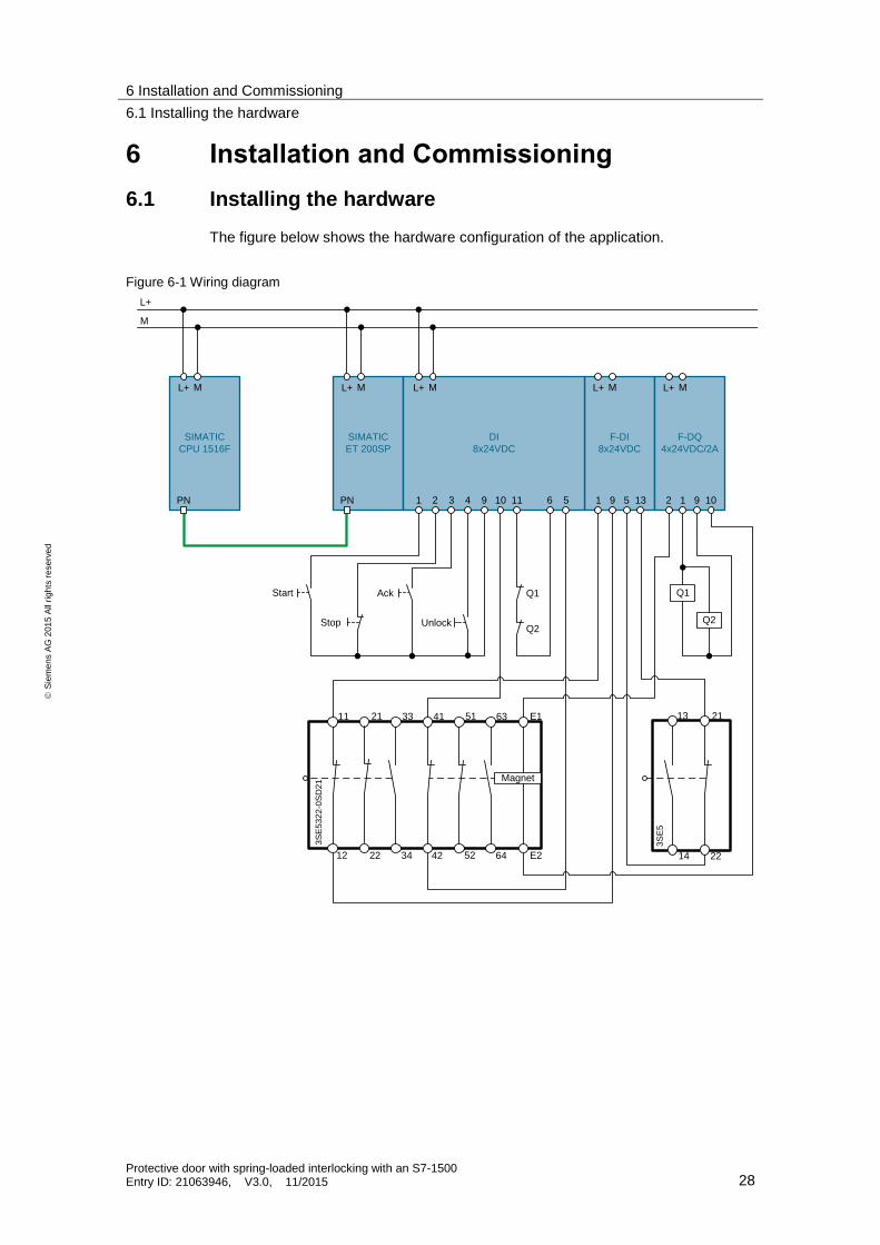
6.1 Installing the hardware
The figure below shows the hardware configuration of the application.
Figure 6-1 Wiring diagram
F-DI
8x24VDC
L+ M
1 9 135
F-DQ
4x24VDC/2A
L+ M
2 10
Q1
Q2
L+
M
SIMATIC
CPU 1516F
L+ M
PN
SIMATIC
ET 200SP
L+ M
PN
13 21
14 22
3S
E5
91
Unlock
Start Ack
Stop
Q1
Q2
11 33 41 51 63 E1
12 22 34 42 52 64 E2
21
Magnet
3S
E5
32
2-0
SD
21
DI
8x24VDC
L+ M
1 2 3 114 10 6 59
6 Installation and Commissioning
6.2 Commissioning
Protective door with spring-loaded interlocking with an S7-1500 Entry ID: 21063946, V3.0, 11/2015 29
S
iem
en
s A
G 2
01
5 A
ll ri
gh
ts r
ese
rve
d
6.2 Commissioning
6.2.1 Preparation
1. Download the “21063946_Protective_door_with_spring_interlocking_CODE_V30.zip” project file. The download can be found in \2\.
2. Save the zip file in any directory on your computer and unzip it.
3. Set the IP address of the PG/PC in a way so that the PG/PC is located in the same subnet as the CPU.
4. Use an Ethernet cable to connect the PG/PC with the Ethernet interface of CPU S7-1516F.
For this application example, the following IP addresses were used:
CPU S7-1516F IP address: 192.168.0.1 Subnet mask: 255.255.255.0
IM 155-6PN IP address: 192.168.0.2 Subnet mask: 255.255.255.0
6.2.2 Loading the S7 project into CPU S7-1516F
1. Open “TIA Portal V13”.
2. Go to the project view.
3. Click “Project > Open” in the menu bar in the TIA Portal.
4. Click “Browse” and open the unzipped project.
5. Set the CPU S7-1516F to STOP.
6. Right click “PLC_1 [CPU1516F-3 PN/DP]” and then “Download to device > Hardware and Software (only changes)”).
7. Select the respective interface and click “Start search”.

6 Installation and Commissioning
6.2 Commissioning
Protective door with spring-loaded interlocking with an S7-1500 Entry ID: 21063946, V3.0, 11/2015 30
S
iem
en
s A
G 2
01
5 A
ll ri
gh
ts r
ese
rve
d
Figure 6-2
8. Select the CPU based on the MAC address and then click “Load”.
Note The IP address and the device name are automatically assigned when downloading the project into the CPU.
Figure 6-3

6 Installation and Commissioning
6.2 Commissioning
Protective door with spring-loaded interlocking with an S7-1500 Entry ID: 21063946, V3.0, 11/2015 31
S
iem
en
s A
G 2
01
5 A
ll ri
gh
ts r
ese
rve
d
9. Confirm the dialog by clicking “Load”.
10. Click “Finish” when the loading process is completed.
6.2.3 Assigning a device name
The device name of the CPU is automatically assigned during the loading process. The device name has to be assigned manually to the ET 200SP. To do this, proceed as follows:
11. Open “Devices & networks” from the project tree.
12. Right click the ET 200SP and select “Assign device name”.
Figure 6-4 Devices & Networks
13. Click on “Update list” and select the detected ET 200SP based on the MAC address.
14. Now click “Assign name” and close the window when the status is marked with “OK”.

6 Installation and Commissioning
6.2 Commissioning
Protective door with spring-loaded interlocking with an S7-1500 Entry ID: 21063946, V3.0, 11/2015 32
S
iem
en
s A
G 2
01
5 A
ll ri
gh
ts r
ese
rve
d
Figure 6-5 Assigning a device name
6.2.4 Assigning F target address
In order to establish a secure communication between the F-CPU and the fail-safe modules of the ET 200SP, the modules have to be assigned F target addresses.
Note Since the F address is saved in the electronic coding element, the following steps are only required if the coding element has not previously been assigned an F address or another F address.
1. Open “Devices & networks” from the project tree.
2. Right click the ET 200SP station and select the “Assign F-destination address” action, see Figure 6-4.
3. Enable the checkbox of the first fail-safe module and click the “Identification” button.
4. When the LEDs of the F-DI are simultaneously flashing green every second, enable the “Confirm” checkbox.
5. Then click the “Assign F-destination address” button and confirm the dialog with “Yes”

6 Installation and Commissioning
6.2 Commissioning
Protective door with spring-loaded interlocking with an S7-1500 Entry ID: 21063946, V3.0, 11/2015 33
S
iem
en
s A
G 2
01
5 A
ll ri
gh
ts r
ese
rve
d
Figure 6-6
6. Repeat the steps for the other fail-safe modules.
7. You can then close the window.
Note All red LEDs of the ET 200SP station should go out after assigning the F-target address. If this is not the case, there may be a fault in the wiring.
8. Now set the CPU S7-1516F to RUN.

7 Operating the Application
7.1 Starting the machine
Protective door with spring-loaded interlocking with an S7-1500 Entry ID: 21063946, V3.0, 11/2015 34
S
iem
en
s A
G 2
01
5 A
ll ri
gh
ts r
ese
rve
d
7 Operating the Application
7.1 Starting the machine
Table 7-1
No. Action Notes
1. Shut the protective door.
2. Press the knob switch, to interlock the protective door.
The power supply at the magnet is interrupted and the locking mechanism engages the actuator.
3. Press the start button. The machine starts.
7.2 Opening the protective door
Table 7-2
No. Action Notes
1. Press the stop button The machine switches off and coasts down.
2. Wait until the configured delay time has elapsed and unlock the protective door.
3. Press the knob switch, to unlock the protective door.
The magnet is supplied with voltage and the locking mechanism disengages the actuator.
4. Open the protective door.
7.3 Acknowledging a discrepancy fault
If the function block for monitoring the position of the protective door detects a discrepancy fault between both position switches (e.g. due to bouncing of a contact or wire break in a channel), the machine is immediately switched off and a restart is prevented. Proceed as follows to acknowledge the fault after it has been repaired.
Table 7-3
No. Action Notes
1. Press the knob switch, to unlock the protective door.
The magnet is supplied with voltage and the locking mechanism disengages the actuator.
2. Open the protective door so both position switches can be actuated.
Both channels report “0”.
3. Shut the protective door. Both channels report “1”, the fault is acknowledged.
4. Press the knob switch, to interlock the protective door.
The power supply at the magnet is interrupted and the locking mechanism engages the actuator.
5. Press the start button The machine starts.

7 Operating the Application
7.4 Acknowledge other faults of the safety function
Protective door with spring-loaded interlocking with an S7-1500 Entry ID: 21063946, V3.0, 11/2015 35
S
iem
en
s A
G 2
01
5 A
ll ri
gh
ts r
ese
rve
d
7.4 Acknowledge other faults of the safety function
If another fault occurs in the safety function, the machine is switched off immediately and a restart is prevented. Proceed as follows to acknowledge the fault.
Possible faults that are acknowledged in this way are, amongst others:
Cross-circuit between both channels of the position switches
External voltage at the fail-safe outputs
Pulling a fail-safe module
Welding of a contactor
Table 7-4
No. Action Notes
1. Checking the LEDs at the ET 200SP. If a red LED lights, a fault in the hardware was detected. Use the online diagnostics in TIA Portal to search for faults.
2. If all LEDs light green, a fault was detected by a function block. Monitoring the tag table to find the fault.
The tags #fault and #ackReq of the instructions of the ProtDoorWithInterlocking block can help during the search.
3. Clear the fault.
4. Shut the protective door.
5. Press the knob switch, to interlock the protective door.
The power supply at the magnet is interrupted and the locking mechanism engages the actuator.
6. Press the acknowledgement button. Detected faults of the function blocks are acknowledged. Passivated channels of the fail-safe modules are reintegrated.
7. Press the start button. The machine starts.
8 Evaluation of the Safety Function
8.1 Standards
Protective door with spring-loaded interlocking with an S7-1500 Entry ID: 21063946, V3.0, 11/2015 36
S
iem
en
s A
G 2
01
5 A
ll ri
gh
ts r
ese
rve
d
8 Evaluation of the Safety Function
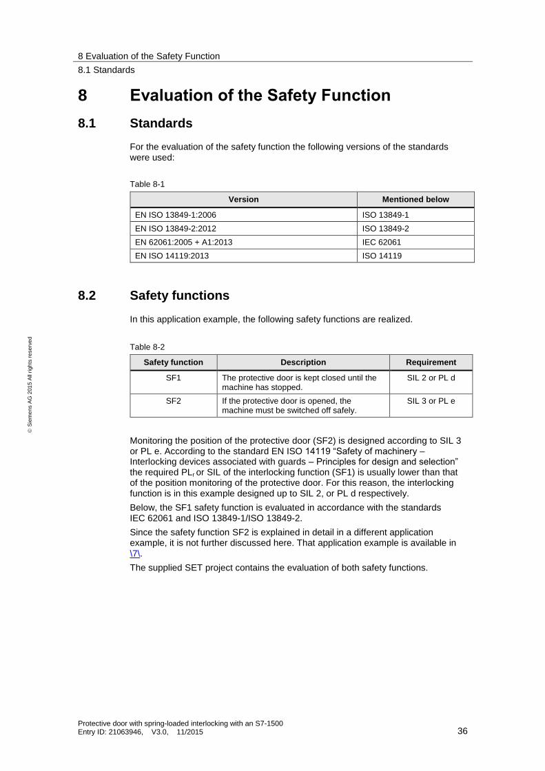
8.1 Standards
For the evaluation of the safety function the following versions of the standards were used:
Table 8-1
Version Mentioned below
EN ISO 13849-1:2006 ISO 13849-1
EN ISO 13849-2:2012 ISO 13849-2
EN 62061:2005 + A1:2013 IEC 62061
EN ISO 14119:2013 ISO 14119
8.2 Safety functions
In this application example, the following safety functions are realized.
Table 8-2
Safety function Description Requirement
SF1 The protective door is kept closed until the machine has stopped.
SIL 2 or PL d
SF2 If the protective door is opened, the machine must be switched off safely.
SIL 3 or PL e
Monitoring the position of the protective door (SF2) is designed according to SIL 3 or PL e. According to the standard EN ISO 14119 “Safety of machinery – Interlocking devices associated with guards – Principles for design and selection” the required PLr or SIL of the interlocking function (SF1) is usually lower than that of the position monitoring of the protective door. For this reason, the interlocking function is in this example designed up to SIL 2, or PL d respectively.
Below, the SF1 safety function is evaluated in accordance with the standards IEC 62061 and ISO 13849-1/ISO 13849-2.
Since the safety function SF2 is explained in detail in a different application example, it is not further discussed here. That application example is available in \7\.
The supplied SET project contains the evaluation of both safety functions.

8 Evaluation of the Safety Function
8.3 Evaluation in accordance with IEC 62061
Protective door with spring-loaded interlocking with an S7-1500 Entry ID: 21063946, V3.0, 11/2015 37
S
iem
en
s A
G 2
01
5 A
ll ri
gh
ts r
ese
rve
d
8.3 Evaluation in accordance with IEC 62061
Below, the evaluation according to safety function SF1 (interlocking function) is performed with the Safety Evaluation Tool (SET) in accordance with IEC 62061. For the link to the SET, please refer to the internet at \4\.
8.3.1 Evaluation of “Detecting”
In this application example, the safe state for enabling the protective door is not detected via sensors, but can be estimated regarding the time if the overrun of the dangerous motion is always the same. The protective door is therefore enabled via a time delay after switching off the actuators that are evaluated in the safety program. After enabling the protective door, it can be unlocked by the operator.
Subsystem “Detecting” is therefore not relevant for this safety function.
8.3.2 Evaluation of “Evaluating”
Explanation
Subsystem “Evaluating” involves the fail-safe controller and the F-DQ module for controlling the interlocking. The position of the interlocking mechanism is read back to the controller via a standard DI. However, as a mere diagnostic function, the standard DI module needs not be considered in the evaluation.
Calculation
Table 8-3
Parameter Component Value Definition
PFHD (F-CPU)
incl. PROFIsafe
CPU 1516F-3PN/DP 2.00 ∙ 10−9 SIEMENS AG
PFHD (F-I/O module) F-DQ of the ET 200SP 1.00 ∙ 10−9
Result
Table 8-4
PFHD SILCL achieved
3.00 ∙ 10−9 SILCL 3
8.3.3 Evaluation of “Reacting”
Explanation
For SF1, the SIRIUS 3SE5 position switch with interlocking represents the subsystem “Reacting”. Correct functioning of the interlocking is monitored by the controller via an NC contact in the position switch. This is a basic subsystem architecture C in accordance with IEC 62061: Zero fault tolerance with diagnostic function.
For a single channel setup (hardware fault tolerance = 0) and DC ≥ 90%, SILCL 2 or 3 can only be achieved with additional measures. That is, after fault detection, a defined safe state of the machine must be initiated with a respective fault reaction. A fault in the interlocking control is detected immediately by the dynamic feedback circuit monitoring and causes the machine to switch off.

8 Evaluation of the Safety Function
8.3 Evaluation in accordance with IEC 62061
Protective door with spring-loaded interlocking with an S7-1500 Entry ID: 21063946, V3.0, 11/2015 38
S
iem
en
s A
G 2
01
5 A
ll ri
gh
ts r
ese
rve
d
The probability that the fault occurs at the very moment the operator tries to access the hazard zone is neglectable (see also chapter 8.4 ISO 14119).
A breaking of the interlocking mechanism is also excluded (see also chapter 8.5 ISO 14119).
Calculation
The safety-relevant parameters of the component are provided by the manufacturer. The resulting probability of a dangerous failure, as well as the SILCL depends on the actual actuation cycles and the installation type of the component to be completed by the user.
Table 8-5
Parameter Value Explanation Definition
B10
Switching cycles
1.000.000 Manufacturer information SIEMENS AG
Dangerous failure fraction
0.20 (20%) Manufacturer information
T1
Lifetime
175,000 h
(20 years)
Manufacturer information
Subsystem architecture
C Zero fault tolerance with diagnostic function
User
Actuations/ test interval
3/day Assumption
Structural restriction
Yes Due to the fault exclusion, structural restrictions apply
DC
Diagnostic coverage
≥ 0.90 (90%) Dynamic monitoring of the interlocking taking into consideration the fault exclusion
Result
Table 8-6
PFHD SILCL achieved
2.50 ∙ 10−10 SILCL 2
8 Evaluation of the Safety Function
8.3 Evaluation in accordance with IEC 62061
Protective door with spring-loaded interlocking with an S7-1500 Entry ID: 21063946, V3.0, 11/2015 39
S
iem
en
s A
G 2
01
5 A
ll ri
gh
ts r
ese
rve
d
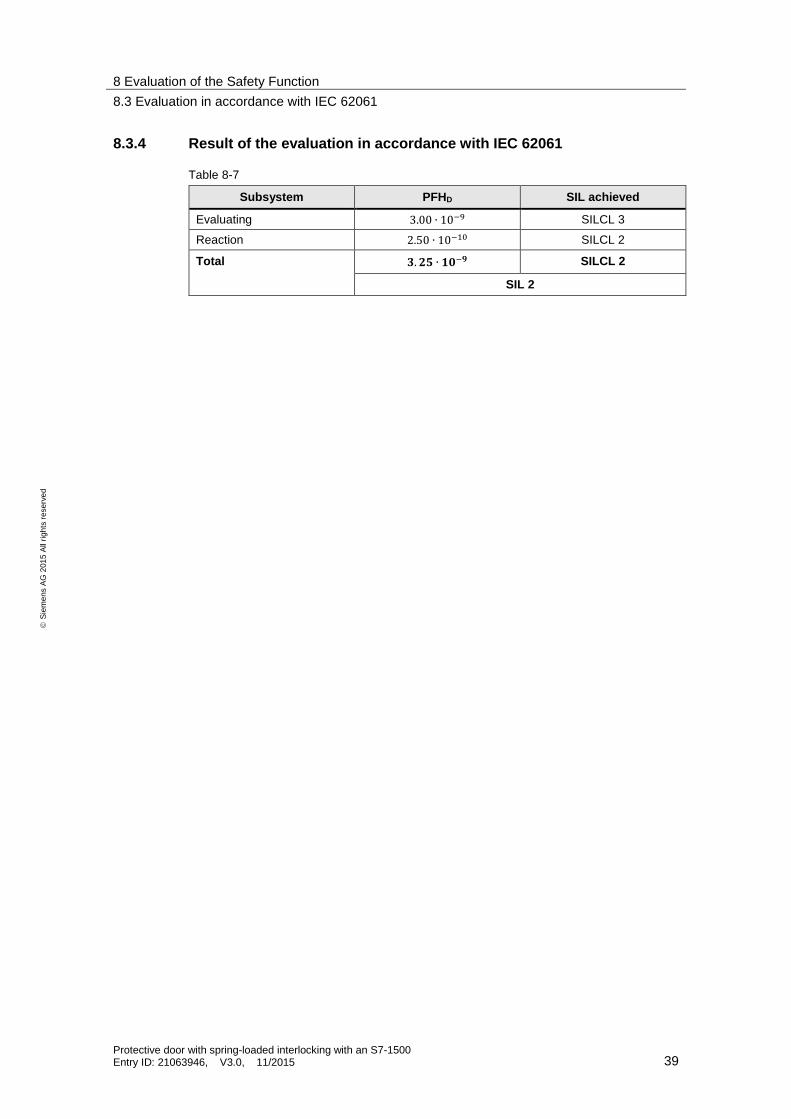
8.3.4 Result of the evaluation in accordance with IEC 62061
Table 8-7
Subsystem PFHD SIL achieved
Evaluating 3.00 ∙ 10−9 SILCL 3
Reaction 2.50 ∙ 10−10 SILCL 2
Total 𝟑. 𝟐𝟓 ∙ 𝟏𝟎−𝟗 SILCL 2
SIL 2

8 Evaluation of the Safety Function
8.4 Evaluation in accordance with ISO 13849-1
Protective door with spring-loaded interlocking with an S7-1500 Entry ID: 21063946, V3.0, 11/2015 40
S
iem
en
s A
G 2
01
5 A
ll ri
gh
ts r
ese
rve
d
8.4 Evaluation in accordance with ISO 13849-1
Below, the evaluation according to safety function SF1 (interlocking function) is performed with the Safety Evaluation Tool (SET) in accordance with ISO 13849-1. For the link to the SET, please refer to the internet at \4\.
8.4.1 Evaluation of “Detecting”
In this application example, the safe state for enabling the protective door is not detected via sensors, but can be estimated regarding the time if the overrun of the dangerous motion is always the same. The protective door is therefore enabled via a time delay after switching off the actuators that are evaluated in the safety program. After enabling the protective door, it can be unlocked by the operator.
Subsystem “Detecting” is therefore not relevant for this application example.
8.4.2 Evaluation of “Evaluating”
Explanation
Subsystem “Evaluating” involves the fail-safe controller and the F-DQ module for controlling the interlocking. The position of the interlocking magnet is read back to the controller via a standard DI. However, as a mere diagnostic function, the standard DI needs not be considered in the evaluation.
Calculation
Table 8-8
Parameter Component Value Definition
PFHD (F-CPU)
incl. PROFIsafe
CPU 1516F-3PN/DP 2.00 ∙ 10−9 SIEMENS AG
PFHD (F-I/O module) F-DQ of the ET 200SP 1.00 ∙ 10−9
Result
Table 8-9
PFHD PL achieved
3.00 ∙ 10−9 PL e
8 Evaluation of the Safety Function
8.4 Evaluation in accordance with ISO 13849-1
Protective door with spring-loaded interlocking with an S7-1500 Entry ID: 21063946, V3.0, 11/2015 41
S
iem
en
s A
G 2
01
5 A
ll ri
gh
ts r
ese
rve
d
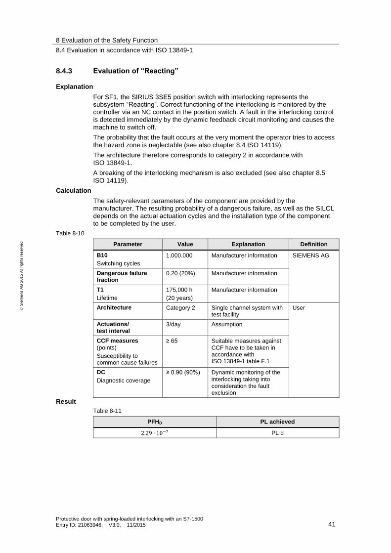
8.4.3 Evaluation of “Reacting”
Explanation
For SF1, the SIRIUS 3SE5 position switch with interlocking represents the subsystem “Reacting”. Correct functioning of the interlocking is monitored by the controller via an NC contact in the position switch. A fault in the interlocking control is detected immediately by the dynamic feedback circuit monitoring and causes the machine to switch off.
The probability that the fault occurs at the very moment the operator tries to access the hazard zone is neglectable (see also chapter 8.4 ISO 14119).
The architecture therefore corresponds to category 2 in accordance with ISO 13849-1.
A breaking of the interlocking mechanism is also excluded (see also chapter 8.5 ISO 14119).
Calculation
The safety-relevant parameters of the component are provided by the manufacturer. The resulting probability of a dangerous failure, as well as the SILCL depends on the actual actuation cycles and the installation type of the component to be completed by the user.
Table 8-10
Parameter Value Explanation Definition
B10
Switching cycles
1.000.000 Manufacturer information SIEMENS AG
Dangerous failure fraction
0.20 (20%) Manufacturer information
T1
Lifetime
175,000 h
(20 years)
Manufacturer information
Architecture Category 2 Single channel system with test facility
User
Actuations/ test interval
3/day Assumption
CCF measures
(points)
Susceptibility to common cause failures
≥ 65 Suitable measures against CCF have to be taken in accordance with ISO 13849-1 table F.1
DC
Diagnostic coverage
≥ 0.90 (90%) Dynamic monitoring of the interlocking taking into consideration the fault exclusion
Result
Table 8-11
PFHD PL achieved
2.29 ∙ 10−7 PL d
8 Evaluation of the Safety Function
8.4 Evaluation in accordance with ISO 13849-1
Protective door with spring-loaded interlocking with an S7-1500 Entry ID: 21063946, V3.0, 11/2015 42
S
iem
en
s A
G 2
01
5 A
ll ri
gh
ts r
ese
rve
d
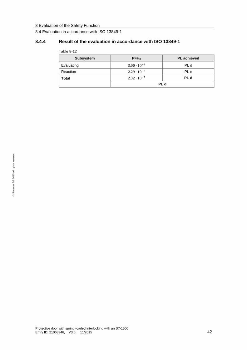
8.4.4 Result of the evaluation in accordance with ISO 13849-1
Table 8-12
Subsystem PFHD PL achieved
Evaluating 3.00 ∙ 10−9 PL d
Reaction 2.29 ∙ 10−7 PL e
Total 2.32 ∙ 10−7 PL d
PL d

9 Links & Literature
Protective door with spring-loaded interlocking with an S7-1500 Entry ID: 21063946, V3.0, 11/2015 43
S
iem
en
s A
G 2
01
5 A
ll ri
gh
ts r
ese
rve
d
9 Links & Literature Table 9-1
Topic Title
\1\ Siemens Industry Online Support
https://support.industry.siemens.com
\2\ Download page of the entry
https://support.industry.siemens.com/cs/ww/de/view/21063946
\3\ Functional Safety at Siemens
www.siemens.com/safety-integrated
\4\ Safety Evaluation Tool (SET)
http://siemens.com/safety-evaluation-tool
\5\ SIMATIC Safety - Configuring and Programming
https://support.industry.siemens.com/cs/ww/en/view/54110126
\6\ SIRIUS position switch product website
https://www.siemens.com/sirius-detecting
\7\ Monitoring the position of a protective door up to SIL 3 / PL e
https://support.industry.siemens.com/cs/ww/en/view/21331363
10 History
Table 10-1
Version Date Modifications
V1.0 02/2005 First version
V2.0 11/2007 Updating the contents regarding:
Hardware and software
Performance data
Screenshots
Evaluation of the application in accordance with new standards IEC 62061 and ISO 13849-1
V3.0 11/2015 Migration of the application example to TIA V13 SP1, S7-1500 and ET 200SP
Evaluation of the interlocking function in accordance with IEC 62061 and ISO 13849-1