Appendixes To Nutrient Reduction Technology Cost
56
Appendixes To Nutrient Reduction Technology Cost Estimation For Point Sources In The Chesapeake Bay Watershed November 2002
Transcript of Appendixes To Nutrient Reduction Technology Cost

Appendixes To Nutrient Reduction Technology Cost Estimation
For Point Sources In The Chesapeake Bay Watershed
November 2002

List of Appendixes Appendix A List of NRT Cost Task Force Members Appendix B Point Source NRT Cost Survey Part 1: Point Source Survey Part 2: Point Source Survey Results Appendix C Correspondences Used to Develop Costs for Municipalities Appendix D Description of CSO Tiers for Blue Plains Appendix E Capital Cost Data for Tier 1 for Nitrogen Removal Appendix F Statistical Analyses of Tier 2 Cost Data Appendix G Details of Cost Assumptions Used in the Tier 3 and 4 Methodology Appendix H References and Data Contacts for Industrial Costs Appendix I Communications, Decisions, and References for Cost and Load Data Compiling
Part 1: Communications and Decisions for Cost Methodology Applications Part 2: Communications and Decisions for Load Calculations by Tier Part 3: References for Section IX Summary Cost Tables
Appendix A:
List of NRT Cost Task Force Members
A - i
Appendix A: List of NRT Cost Task Force Members
NRT Cost Task Force Membership
Allison Wiedeman EPA Chesapeake Bay Program
Bob Ehrhart VA Department of Environmental Quality
Bob Steidel Hopewell Regional Wastewater Treatment Facility
Chris Pomeroy AQUALAW
Cliff Randall Virginia Tech
Dave Waltrip Hampton Roads Sanitation District
Glen Harvey Alexandria Sanitation Authority
Jerusalem Bekele DC Department of Health
John Kennedy VA Department of Environmental Quality
John Murtha PA Department of Environmental Protection
Lisa Bacon CH2M HILL
Marya Levelev MD Department of the Environment
Mike Kyle Lancaster Area Sewer Authority
Ning Zhou Virginia Tech
Tanya Spano Metropolitan Washington Council of Governments
Ta-shon Yu MD Department of the Environment
Thor Young Stearns & Wheler
Tom Sadick CH2M HILL
A - ii

Appendix B:
Point Source NRT Cost Survey
Part 1: Point Source Survey Letter and Attachment Part 2: Point Source Survey Responses (Part II is available in hard copy by contacting Ning Zhou at the Chesapeake Bay Program Office at 410-267-5727 or [email protected])
B - i

Appendix B, Part 1: The Survey Letter and Attachment
Dear Wastewater Treatment Plant Contact: Attached please find a cost estimate for implementation of nutrient reduction technology at your facility. This information was obtained either from previous correspondence with your facility, grant agreement information, or state reports. This information reflects only the incremental costs necessary to remove nitrogen. The Chesapeake Bay Program is currently performing an analysis of data to estimate costs for all municipal facilities in the Chesapeake Bay watershed to implement Nutrient Removal Technology. Nutrient Removal Technology (NRT) is considered to be any method employed to remove nitrogen from wastewaters including, but not limited to, Biological Nutrient Removal (BNR). Critical information as a part of this work is site specific cost to achieve Biological Nutrient Removal (BNR is defined for this study as: an annual average, non regulatory, final effluent nitrogen concentration of 8 mg/l Total Nitrogen). Information on cost to obtain Limit of Technology (LOT is defined for this study as an annual average, non regulatory, final effluent concentration of 3 mg/l Total Nitrogen) is also desired if available. Estimates for your facility will be a part of this analysis to determine NRT costs Bay-wide; thus, it is important the information be reviewed to ensure its accuracy. Please note, this information will be used in a Bay-wide cost analysis and is not intended to be used for other purposes such as grant applications, etc. The Bay program is required to provide these cost estimates by May of this year. In order to complete this requirement it is necessary that all cost data that will be used be finalized by March 2002. If data is not available for your facility then your cost will have to be estimated based upon typical values. In addition to the dollar amounts provided in the attachment, there are a number of assumptions that are related to the derivation of costs that need confirmation as well. Please take a look at the attachment and provide a response by March 1, 2002 to the contact provided on the attachment. Your assistance in this matter would be very much appreciated. Sincerely,
B - ii

Attachment Wastewater Treatment Facility NRT Cost Information
Name of Facility:__________________________________________________________ Facility Contact (name and phone #)_______________________________________ Design Flow ________MGD 2000 Annual Ave Flow_______________ What is your current treatment process? (circle one) BNR Activated Sludge Trickling Filter SBR RBC Other (Please specify)
______________________ I s this facility currently designed to allow year round nitrification? Yes No
Are there significant site or design constraints that influence the cost to obtain BNR at your facility? Yes No If yes provide short explanation (example: HPO plant with no available land for expansion) and an estimate of the additional costs to compensate for this constraint: ____________________________________________________________________________ ____________________________________________________________________________ Please confirm, or provide, the following information: The costs to implement BNR (around annual average 8 mg/l TN) at your facility is : $ _____________ in Capital Costs, ( in ___________(year)dollars), and $______________ per year in Operation and Maintenance Costs T
he costs to implement LOT (annual average 3 mg/l TN) at your facility would be :
$ _____________ in Capital Costs, ( in ___________(year)dollars), and $______________ per year in Operation and Maintenance Costs The items included in the derivation of these cost values include the following (please put a check by all hat apply): t
Capital Costs Operation and Maintenance Costs Tanks, Channels and Buildings Power Yard Piping Methanol Pumps and Mechanicals Other Chemicals Sitework Labor Solids Handling Solids Handling Electrical & Instrumentation Equipment Construction Phase Changes Other?____________________ Engineering Design Grant Application Legal Fees Administration Methanol Addition Systems Other? ___________________ I s this a cost value based on voluntary or regulatory implementation? (Circle one)
Please send a response by March 1, 2002 to: Ning Zhou, Point Source Database Manager, Chesapeake Bay Program, 410 Severn Ave, Annapolis, MD 21403 410-267-5727 (phone) 410-267-5777 (fax), [email protected]
B - iii

Appendix C
Correspondences used in developing costs for municipalities This Appendix is organized by state and available in hard copy only by contacting Ning Zhou at the Chesapeake Bay Program Office at 410-267-5727 or [email protected]
C - i

Appendix D
Description of CSO Tiers for Blue Plains
D - i

Appendix D: CBP's Tiered Scenarios for CS0 in DC (as 2/22/02) CSO Assumptions Tier 1 Tier 2 Tier 3 Tier 4 (E3)
Assumptions (Note: All tiers are assumed to be defined in year 2010.)
Assumes an approximately 43% reduction in CSOs, and therefore assumes an equal % reduction in TN, TP, & TSS. This scenario is based on: 1) Use of updated CSO loading figures; and 2) implementation of specific projects authorized under DC-WASA's existing CIP budget. These project are expected to be completed in approximately 8 years (i.e., 2010) and have therefore been incorporated as 'phase 1' of the DC-WASA Draft CSO LTCP currently under review by EPA.
Assumes an approximately 43% reduction in CSOs, and therefore assumes an equal % reduction in TN, TP, & TSS. This scenario is based on: 1) Use of updated CSO loading figures; 2) implementation of specific projects authorized under DC-WASA's existing CIP budget (implemented in 8 years); and 3) approval of the DC-WASA CSO LTCP by EPA.
Assumes an approximately 43% reduction in CSOs, and therefore assumes an equal % reduction in TN, TP, & TSS. This scenario is based on: 1) Use of updated CSO loading figures; 2) implementation of specific projects authorized under DC-WASA's existing CIP budget (implemented in 8 years); and 3) approval of the DC-WASA CSO LTCP by EPA.
CBP Assumed Zero Overflows. Note 1: This scenario was not supported by COG staff or DC-WASA even for the E3 scenario because: 1) Zero CSO overflows requires complete separation of sewer and stormwater flows that could only be accomplished by tearing up the majority of the District of Columbia over a 30-40 year period - regardless of political will and unlimited funding, and therefore exceeds even the 'extreme' definition of E3; and 2) The impact of the diverted stormwater would result in increased stormwater loads and which water quality modeling has shown to actually result in making water quality worse in the receiving waterbody. Note 2: The current draft of the DC-WASA CSO LTCP outlines a 20-year implementation period (i.e., year 2022) due to the physical time required to construct the significant tunnel infrastructure that is proposed and the complexity of such projects. Even the 93% reductions planned under the LTCP would exceed the Tier 4 (E3) definition.
Total Nitrogen: 70,298 lb/yr
Total Nitrogen: 70,298 lb/yr
Total Nitrogen: 70,298 lb/yr
Total Nitrogen: 0 lb/yr from CSOs (Stormwater loads increase by an unquantified amount.)
Total Phosphorus: 15,330 lb/yr
Total Phosphorus: 15,330 lb/yr
Total Phosphorus: 15,330 lb/yr
Total Phosphorus: 0 lb/yr from CSOs (Stormwater loads increase by an unquantified amount.)
Note: CSO loadings have been updated to reflect latest estimates from DC-WASA's CSO LTCP study (2001). These recalculated loads are: Total Nitrogen - 123,329 lb/yr; Total Phosphorus - 26,894 lb/yr; and Total Suspended Solids - 4.23 million lb/yr.
Calculated Load
Total Suspended Sediment: 2.41 million lb/yr
Total Suspended Sediment: 2.41 million lb/yr
Total Suspended Sediment: 2.41 million lb/yr
Total Suspended Sediment: 0 million lb/yr from CSOs (Stormwater loads increase by an unquantified amount.)
D - ii

Appendix E
Capital Cost Data for Tier 1 for Nitrogen Removal
E - i

Appendix E: Nitrogen Removal Capital Cost Data for Tier 1 Methodology
STATE FACILITY DESIGN
FLOW CC@8($)Year of Cost
Estimate Source of Estimate * CC@8 (2000$)
MD ABERDEEN 4 2,388,974 1998 CC $2,493,241 MD ANNAPOLIS 10 13,550,000 1999 CC $13,875,420 MD BALLENGER CREEK 6 2,000,000 1995 CC $2,275,153 MD BOWIE 3.3 225,532 1991 CC $290,134 MD BROADNECK 6 2,163,794 1994 CC $2,461,481 MD BROADWATER 2 5,911,212 1998 CC $6,169,207 MD CAMBRIDGE 8.1 9,934,376 2002 CC $9,817,860 MD CELANESE 1.25 5,791,500 2002 DE $5,723,574 MD CHESAPEAKE BEACH 1.18 1,360,000 1992 CC $1,698,320 MD COX CREEK 15 $9,476,780 2002 CC $9,365,631 MD CRISFIELD 1 4,052,200 2002 DE $4,004,673 MD CUMBERLAND 15 10,367,450 2001 CC $10,265,922 MD DAMASCUS 1.5 1,661,200 1998 CC $1,733,703 MD DELMAR 0.65 1,030,000 2002 DE $1,017,920 MD DENTON 0.8 3,611,714 1999 CC $3,698,454 MD DORSEY RUN 2 2,500,000 1992 CC $3,121,912 MD EASTON 2.35 5,800,000 1993 CC $6,851,202 MD ELKTON 2.7 6,360,000 2002 DE $6,285,406 MD EMMITSBURG 0.75 7,900,000 1996 CC $8,728,723 MD FREDERICK CITY 8 8,816,824 2002 CC $8,713,415 MD FREEDOM DISTRICT 3.5 1,000,000 1994 CC $1,137,576 MD HAVRE DE GRACE 1.89 6,278,550 2002 CC $6,204,912 MD INDIAN HEAD 0.5 656,000 2002 DE $648,306 MD JOPPATOWNE 0.95 1,739,998 1996 CC $1,922,527 MD KENT ISLAND 2.135 $20,742,570 2002 DE $20,499,289 MD LA PLATA 1 4,120,970 2002 CC $4,072,637 MD LEONARDTOWN 0.68 1,840,000 2002 CC $1,818,419 MD MARYLAND CITY 2.5 823,000 1990 CC $1,077,941 MD MARYLAND CORR. INST. 1.23 1,870,000 1995 CC $2,127,268 MD MATTAWOMAN 15 7,935,800 2002 DE $7,842,724 MD MOUNT AIRY 1.2 4,010,000 1999 CC $4,106,305 MD NICODEMUS 1.6 200,000 2002 CC $197,654 MD NORTHEAST RIVER 2 1,800,000 2002 DE $1,778,889 MD PARKWAY 7.5 15,500,000 1992 CC $19,355,857 MD PATUXENT 7.5 1,260,200 1990 CC $1,650,573 MD PISCATAWAY 30 19,485,416 2000 CC $19,485,416 MD SOD RUN 20 17,300,000 1999 CC $17,715,480 MD TANEYTOWN 1.1 3,166,000 2000 CC $3,166,000 MD THURMONT 1 2,216,504 1996 CC $2,449,019 MD WESTERN BRANCH 30 32,596,340 1991 CC $41,933,278 MD WESTMINSTER 5 4,231,847 2001 CC $4,190,405 PA ELIZABETHTOWN BOROUGH 3 8,400,000 2002 CC $8,301,480 PA HARRISBURG SEW. AUTH. 37.7 25,448,000 1999 DE $26,059,164 PA LANCASTER AREA SEW. AUTH. 15 4,249,333 2002 FP $4,199,494 PA LANCASTER CITY 29.73 2,500,000 2002 FP $2,470,679 PA WYOMING VALLEY 50 763,000 2002 FP $754,051
E - ii

Appendix E (continued): Nitrogen Removal Capital Cost Data for Tier 1 Methodology
STATE FACILITY DESIGN
FLOW CC@8($)Year of Cost
Estimate Source of Estimate * CC@8 (2000$)
VA ALEXANDRIA 54 40,295,000 1999, 2000 CC** $40,470,807 VA AQUIA 6.5 704,000 1990 CC $922,078 VA ARLINGTON 40 21,633,946 1999, 2000 CC** $21,710,798 VA CULPEPER 4.5 3,147,100 2000 PER/FP $3,147,100 VA DALE CITY #1 4 6,929,000 2000 CC $6,929,000 VA DALE CITY #8 4 7,122,000 2000 CC $7,122,000 VA FMC 5.4 3,800,000 2000 DE $3,800,000 VA FWSA OPEQUON 8.4 5,388,236 1998 CC $5,623,405 VA H.L. MOONEY 18 18,188,676 1999, 2000 CC/DE** $18,394,217
VA HARRISONBURG-ROCKINGHAM REG. SA 16 5,743,094 1995, 1999 CC** $6,057,948
VA HENRICO COUNTY 75 17,970,000 1994, 1999 CC** $19,108,369 VA LEESBURG 4.85 12,955,468 1998 CC $13,520,909 VA LITTLE FALLS RUN 4 3,979,981 1990, 2001 CC** $5,098,611 VA MASSAPONAX 8 8,766,902 2000 CC $8,766,902 VA MIDDLE RIVER 6.8 2,598,866 1999 CC $2,661,281
VA NOMAN M. COLE POLUTN. CONTR. PLNT. 67 20,799,000 1995, 1997 CC** $22,159,902
VA PROCTORS CREEK 21.5 1,931,120 1991 CC $2,484,273 VA PURCELLVILLE 1 3,030,059 2000 CC $3,030,059 VA REMINGTON REGIONAL 2 1,640,276 1995, 2001 CC/DE** $1,805,477 VA STUARTS DRAFT 1.4 2,730,249 2000 CC $2,730,249 VA TOTOPOTOMOY 5 4,219,540 2000 CC $4,219,540
* Sources include: Construction cost (CC), Engineering Design Estimate (DE), and Facilities Plan (FP)
Note: Other cost estimates have been eliminated from the data table. ** Project costs were estimated for phases occuring in different years. Each phase cost was converted to 2000$ and the total cost is shown.
E - iii

Appendix F
Statistical Analyses of Tier 2 Cost Data
F - i
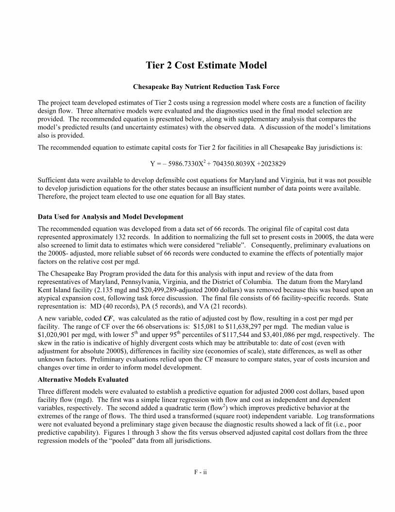
Tier 2 Cost Estimate Model
Chesapeake Bay Nutrient Reduction Task Force
The project team developed estimates of Tier 2 costs using a regression model where costs are a function of facility design flow. Three alternative models were evaluated and the diagnostics used in the final model selection are provided. The recommended equation is presented below, along with supplementary analysis that compares the model’s predicted results (and uncertainty estimates) with the observed data. A discussion of the model’s limitations also is provided.
The recommended equation to estimate capital costs for Tier 2 for facilities in all Chesapeake Bay jurisdictions is:
Y = – 5986.7330X2 + 704350.8039X +2023829
Sufficient data were available to develop defensible cost equations for Maryland and Virginia, but it was not possible to develop jurisdiction equations for the other states because an insufficient number of data points were available. Therefore, the project team elected to use one equation for all Bay states.
Data Used for Analysis and Model Development
The recommended equation was developed from a data set of 66 records. The original file of capital cost data represented approximately 132 records. In addition to normalizing the full set to present costs in 2000$, the data were also screened to limit data to estimates which were considered “reliable”. Consequently, preliminary evaluations on the 2000$- adjusted, more reliable subset of 66 records were conducted to examine the effects of potentially major factors on the relative cost per mgd.
The Chesapeake Bay Program provided the data for this analysis with input and review of the data from representatives of Maryland, Pennsylvania, Virginia, and the District of Columbia. The datum from the Maryland Kent Island facility (2.135 mgd and $20,499,289-adjusted 2000 dollars) was removed because this was based upon an atypical expansion cost, following task force discussion. The final file consists of 66 facility-specific records. State representation is: MD (40 records), PA (5 records), and VA (21 records).
A new variable, coded CF, was calculated as the ratio of adjusted cost by flow, resulting in a cost per mgd per facility. The range of CF over the 66 observations is: $15,081 to $11,638,297 per mgd. The median value is $1,020,901 per mgd, with lower 5th and upper 95th percentiles of $117,544 and $3,401,086 per mgd, respectively. The skew in the ratio is indicative of highly divergent costs which may be attributable to: date of cost (even with adjustment for absolute 2000$), differences in facility size (economies of scale), state differences, as well as other unknown factors. Preliminary evaluations relied upon the CF measure to compare states, year of costs incursion and changes over time in order to inform model development.
Alternative Models Evaluated
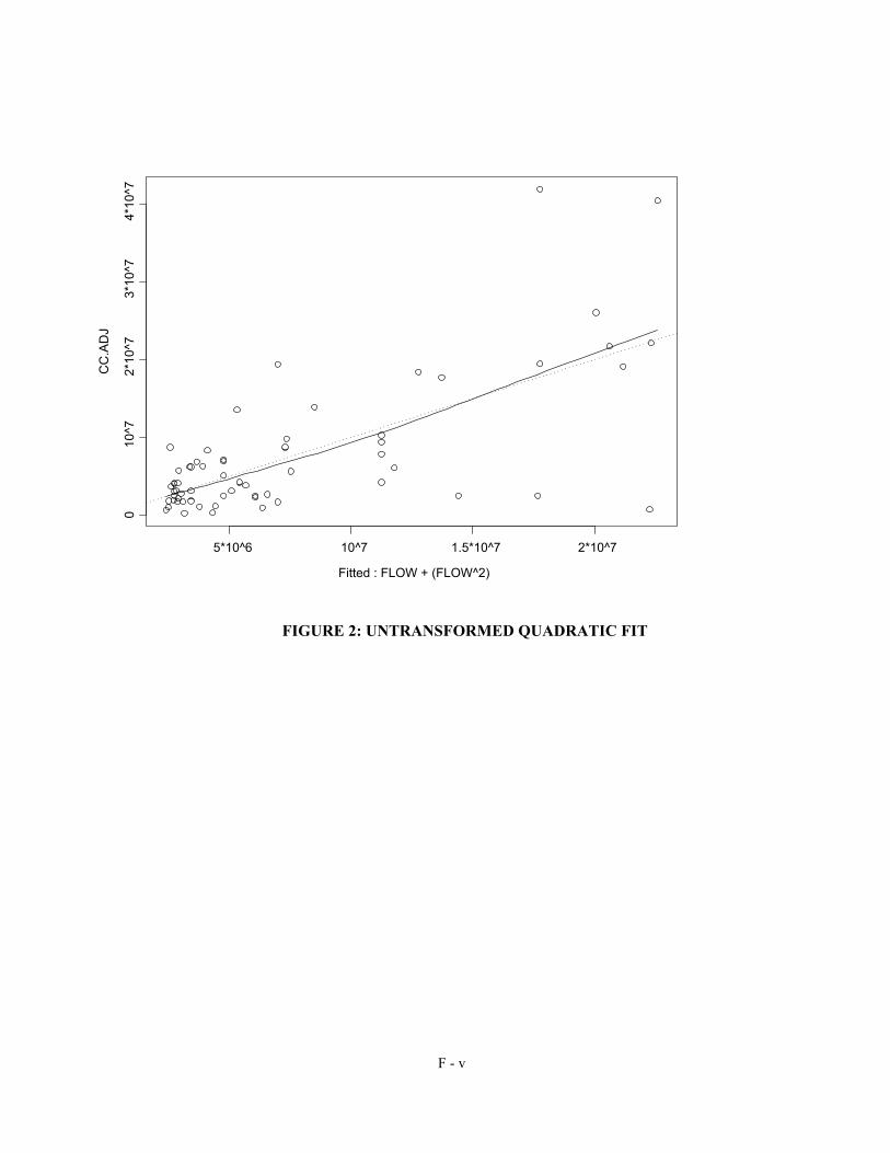
Three different models were evaluated to establish a predictive equation for adjusted 2000 cost dollars, based upon facility flow (mgd). The first was a simple linear regression with flow and cost as independent and dependent variables, respectively. The second added a quadratic term (flow2) which improves predictive behavior at the extremes of the range of flows. The third used a transformed (square root) independent variable. Log transformations were not evaluated beyond a preliminary stage given because the diagnostic results showed a lack of fit (i.e., poor predictive capability). Figures 1 through 3 show the fits versus observed adjusted capital cost dollars from the three regression models of the “pooled” data from all jurisdictions.
F - ii

Among the three models, the quadratic equation displayed the best fit overall. The following bullets summarize results from the model fitting. The equations and diagnostic information for the various models are provided in Table 1.
Most of the information in Table 1 documents model attributes which are used to compare models. While R2 - values are often cited in support of goodness of fit (the higher the value, the more useful the fit), conventional regression diagnostics focus an ANOVA which compares the mean square attributable to the regression to the mean square of the residuals. The ratio of those two values is distributed as an F-statistic, which indicates the probability of the linear function in rejecting the null hypothesis of no correlation. High F-values correspond to low probability (for fixed degrees of freedom), meaning that the relationship is “statistically significant.”
While there are increases in the cases of outliers and leverage points, behavior of the estimates suggested an overall improvement with the addition of the quadratic term. (The “leverage” measures test for the effect of individual points on the slope-intercept estimates. This relates to sufficiency and/or completeness of an equation.)
The final terms in table—SE/FIT and CI/FIT—document the relative percent that the estimated standard error of the model exhibits over the range of predicted values. A confidence interval on a regression line does not parallel the best fit. Rather, the confidence interval exhibits wider divergence from the predicted values at the upper and lower bounds of the range of the independent variable. These terms give the range (percentage) spanned for the ratio of the standard error to the predicted values on the fit line and the range (percentage) spanned by the width of a 95% confidence interval (as a portion of the predicted value) over the range of observed flows. In general, the lower the standard error, the less uncertain the predicted values derived from the regression equation.
Results of this analysis indicated a modest improvement to the linear model with addition of the quadratic term, and no improvement with the square root term.
TABLE 1. MODEL DIAGNOSTICS FOR POOLED DATA (ALL STATES, 66 DATA POINTS)
Equation Type Linear Quadratic Square Root
Equation Y = 351071.9793X + 3648055
Y = –5986.7330X2 +
704350.8039X + 2023829
Y = 3028405.129 SQRT(X) - 679550
R2 0.43 0.48 0.46
R2 ADJ 0.42 0.47 0.45
FDF 48.11,64 52.22,63 48.11,64
p[F] <0.001 <0.001 <0.001
Outlier CASES 5 & 66 Cases 5, 33, & 66 CASES 5, 33 & 66
Leverage CASES 14 & 19 Cases 14 & 19 NA
SE/FIT 8.7 => 25.1 10 => 45 8 => 77
CI/FIT 45 => 100 31 => 182 40 => 309
F - iii

Fitted : FLOW
CC
.AD
J
5*10^6 10^7 1.5*10^7 2*10^7 2.5*10^7 3*10^7
010
^72*
10^7
3*10
^74*
10^7
FIGURE 1: UNTRANSFORMED LINEAR FIT
F - iv
Fitted : FLOW + (FLOW^2)
CC
.AD
J
5*10^6 10^7 1.5*10^7 2*10^7
010
^72*
10^7
3*10
^74*
10^7
FIGURE 2: UNTRANSFORMED QUADRATIC FIT
F - v

Fitted : sqrt(FLOW)
CC
.AD
J
5*10^6 10^7 1.5*10^7 2*10^7 2.5*10^7
010
^72*
10^7
3*10
^74*
10^7
FIGURE 3: SQUARE ROOT EQUATION
Selection of Preferred Model
Overall, the quadratic equation provides a best fit for the available data. None of the models is ideally representative over the range of values. The recommended model was selected on the basis of a comparison of the predictive capabilities of the three alternative models in addition to the modest improvement of equation fit described above.
Table 2 provides comparison of predicted values from the three models (with estimates of uncertainty) to observed values for a subset of flows which span the range observed in available data: 0.5, 1, 5, 15, 30, 50/54 and 75 mgd. The table lists counts of observations, the range of reported adjusted costs, the best estimate (and standard error as a percent of the estimate at that flow), and the 95 percent confidence interval for each flow for the three models.
Figure 4 graphically compares the estimates produced by the three equations over the flow range, 0 to 30 mgd, for which the equation will be used. The quadratic equation provides the most conservative estimates over the broadest range of values for which the equation will be used. The project team used this feature, in conjunction with the statistical analysis discussed above, to help determine that this was the best equation to use for this study.
F - vi
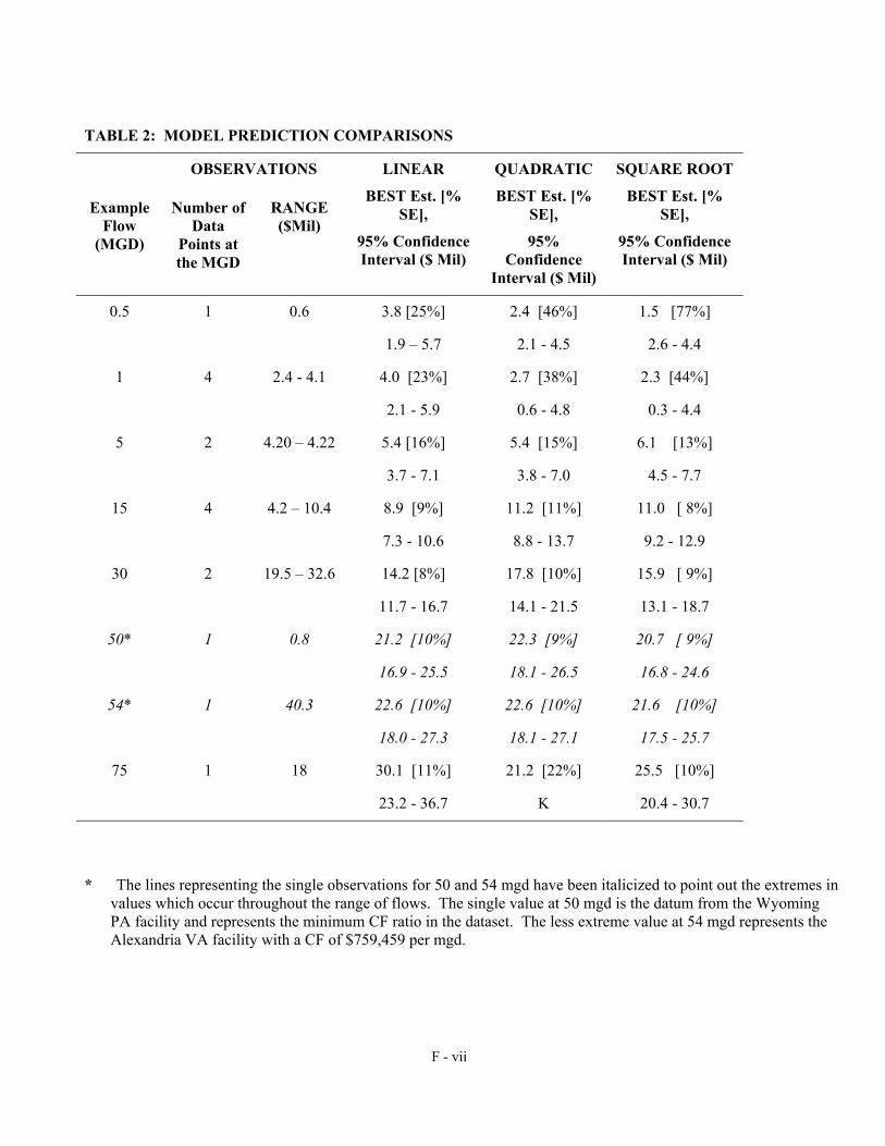
TABLE 2: MODEL PREDICTION COMPARISONS
OBSERVATIONS LINEAR QUADRATIC SQUARE ROOT
Example Flow
(MGD)
Number of Data
Points at the MGD
RANGE ($Mil)
BEST Est. [% SE],
95% Confidence Interval ($ Mil)
BEST Est. [% SE],
95% Confidence
Interval ($ Mil)
BEST Est. [% SE],
95% Confidence Interval ($ Mil)
0.5 1 0.6 3.8 [25%] 2.4 [46%] 1.5 [77%]
1.9 – 5.7 2.1 - 4.5 2.6 - 4.4
1 4 2.4 - 4.1 4.0 [23%] 2.7 [38%] 2.3 [44%]
2.1 - 5.9 0.6 - 4.8 0.3 - 4.4
5 2 4.20 – 4.22 5.4 [16%] 5.4 [15%] 6.1 [13%]
3.7 - 7.1 3.8 - 7.0 4.5 - 7.7
15 4 4.2 – 10.4 8.9 [9%] 11.2 [11%] 11.0 [ 8%]
7.3 - 10.6 8.8 - 13.7 9.2 - 12.9
30 2 19.5 – 32.6 14.2 [8%] 17.8 [10%] 15.9 [ 9%]
11.7 - 16.7 14.1 - 21.5 13.1 - 18.7
50* 1 0.8 21.2 [10%] 22.3 [9%] 20.7 [ 9%]
16.9 - 25.5 18.1 - 26.5 16.8 - 24.6
54* 1 40.3 22.6 [10%] 22.6 [10%] 21.6 [10%]
18.0 - 27.3 18.1 - 27.1 17.5 - 25.7
75 1 18 30.1 [11%] 21.2 [22%] 25.5 [10%]
23.2 - 36.7 K 20.4 - 30.7
* The lines representing the single observations for 50 and 54 mgd have been italicized to point out the extremes in values which occur throughout the range of flows. The single value at 50 mgd is the datum from the Wyoming PA facility and represents the minimum CF ratio in the dataset. The less extreme value at 54 mgd represents the Alexandria VA facility with a CF of $759,459 per mgd.
F - vii

0
5000
10000
15000
20000
25000
30000
0 5 10 15 20 25 30Flow (MGD)
Cos
t ($1
000)
Linear FitQuadratic FitSquare Root Fit
FIGURE 4: COMPARISON OF EQUATION ESTIMATES OVER THE 0 TO 30 MGD FLOW RANGE
F - viii
Appendix G
Details of Cost Assumptions Used in the Tier 3&4 Methodology
G - i

Facility/component 0.1mgd 1.0 mgd 10 mgd 30 mgd Comments/assumptions
Secondary anoxic reactor 11 105 1,040 3,125 1 hr HRT using $ 2.50 per gallon installed w/ bafflesMixing/misc mechanical 10 50 200 500 Allowance
Nitrification improvements allowance 50 250 1,000 3,000
Guesstimate based on flow per gallon - $.50 for 0.1 mgd, $.25 for 1 mgd, and $0.10 for 10 and 30 mgd for improvements to achieve more reliable nitrification for LOT. E.g., Q splits, aeration, tankage
Methanol facility 75 250 500 800Used in-house estimates and judgement. 55 Gallon drums for 0.1 mgd, bulk storage for others
Clarifier improvements 40 200 1,050 2,100
Assumed clarifiers added for 25% of flow. E.g. for 1 mgd cost use clarifier cost for 250k flow. Used EPA I/A curve for circular clarifier @ 600 gpd/sq ft includes WAS & RAS - ENR 2475
Total Construction 186 855 3,790 9,525
30 % Program Implementation Cost 56 257 1,137 2,858
Total Capital Cost $241 $1,112 $4,927 $12,383 $ x 1,000
Annual O&M Costs $7,046 $29,218 $157,469 $293,938 Actual dollars at design flow
update 4/4/02 tes
Summary of Costs for TN=5 Capital and Operating for Plant Sizes 0.1 to 30 MGD Plant annual average flow
G - ii

Facility/component 0.1mgd 1.0 mgd 10 mgd 30 mgd Comments/assumptions
Secondary anoxic reactor 11 105 1,040 3,125 1 hr HRT using $ 2.50 per gallon installed w/ bafflesMixing/misc mechanical 10 50 200 500 Allowance
Nitrification improvements allowance 50 250 1,000 3,000
Guesstimate based on flow per gallon - $.50 for 0.1 mgd, $.25 for 1 mgd, and $0.10 for 10 and 30 mgd for improvements to achieve more reliable nitrification for LOT. E.g., Q splits, aeration, tankage
Methanol facility 75 250 500 800Used in-house estimates and judgement. 55 Gallon drums for 0.1 mgd, bulk storage for others
Clarifier improvements 40 200 1,050 2,100
Assumed clarifiers added for 25% of flow. E.g. for 1 mgd cost use clarifier cost for 250k flow. Used EPA I/A curve for circular clarifier @ 600 gpd/sq ft includes WAS & RAS - ENR 2475
Total Construction 186 855 3,790 9,525
30 % Program Implementation Cost 56 257 1,137 2,858
Total Capital Cost $241 $1,112 $4,927 $12,383 $ x 1,000
$/gallon $2.41 $1.11 $0.49 $0.41
N removed lbs/ day 3 25 250 750 8 mg/L TN to 5 mg/L TNN removed lbs/ year 913 9,125 91,250 273,750Note: These are incremental costs to go from 8 to 5 mg/L TNupdated 4/4/02 tes
Capital Costs for TN=5 By Components ($000)Plant annual average flow
G - iii

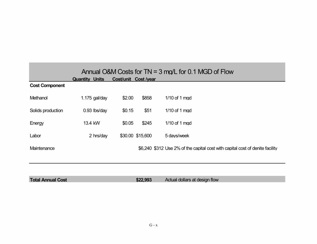
Quantity Units Cost/unit Cost /yearCost Component
Methanol 1.175 gal/day $2.00 $858 1/10 of 1 mgd - use $2 /gal for 55 gallon drums
Solids production 0.93 lbs/MG $0.15 $51 1/10 of 1 mgd
Energy 3 kW/day $0.05 $1,314 Estimate for mixing and other electrical needs
Labor 0 hrs/day $30.00 $0 No extra labor
Maintenance $4,823 $241 Use 2% of the capital cost
Total Annual Cost $7,046 Actual dollars at design flow
Updated 4/4/02
Annual O&M Costs for TN = 5 mg/L for 0.1 MGD of Flow
G - iv

Quantity Units Cost/unit Cost /yearCost Component
Methanol 11.75 gal/day 1 $4,2898 mg/L to 5 mg/L , 3 mg/L NO3 removed*3.1 mg/MeOH/mg/NO3*1*8.34 = 77.56 lbs MeOH /day / 6.6 lbs /gal = 11.75 gal/day @ $1.00/gal
Solids production 9.3 lbs/MG 0.15 $5090.12 lbs /lb MeOH: 77.5 lbs MeOH * 0.12 = 9.3 lbs /MG and use cost of $ 300/dt or $0.15 /dlb
Energy 5 kW 0.05 $2,190
use 50 HP/MG - EPA Nitrogen Control Manual - pg 216, anoxic volume of 41,667/1,000,000 x 50hp/MG = 2.1 HP*.746kW/HP = 1.56 kW say 2 also add 3 kW for clarifier mechanism, metering pumps, lights = 5
Labor 0 hrs/day 30 $0 No extra Labor
Maintenance $22,230 $1,112 Use 2% of the capital cost with capital cost
Total Annual Cost $29,218 Actual dollars at design flow
Updated 4/4/02
Annual O&M Costs for TN = 5 mg/L for 1 MGD of Flow
G - v

Quantity Units Cost/unit Cost /yearCost Component
Methanol 117.5 gal/day $1.00 $42,888 10x1mgd
Solids production 93 lbs/MG $0.15 $5,092 10x 1mgd
Energy 25 kW $0.05 $10,950 0.4 MG anoxic x 50 HP/MG = 20 HP = 15 KW + 5 for other electrical
Labor 0 hrs/day $30.00 $0 No extra labor
Maintenance $98,540 $4,927 Use 2% of the capital cost with capital cost of denite facility
Total Annual Cost $157,469 Actual dollars at design flow
updated 4/4/02
Annual O&M Costs for TN = 5 mg/L for 10 MGD of Flow
G - vi

Quantity Units Cost/unit Cost /yearCost Component
Methanol 352.5 gal/day $1.00 $353 30x1mgd
Solids production 279 lbs/MG $0.15 $15,275 30x1mgd
Energy 70 kW $0.05 $30,660 1.25 MG x 50 = 75 HP*.746= 56 use 70 with other electrical needs
Labor 0 hrs/day $30.00 $0 no extra labor
Maintenance $247,650 $12,383 Use 2% of the capital cost with capital cost of denite facility
Total Annual Cost $293,938 Actual dollars at design flow
updated 4/4/02
Annual O&M Costs for TN = 5 mg/L for 30 MGD of Flow
G - vii

Facility/component 0.1mgd 1.0 mgd 10 mgd 30 mgd Comments/assumptions
Pumping station 140 350 1,400 3,200
Using approximate average for two sets of EPA cost curves - IA manual and Construction Cost Curves for Muni WW Conveyance Systems - Used 3x ADF for costs e.g., 0.1 = 0.3 peak capacity
Denite filters 100 625 6,000 17,200
Used 2 gpm/sq ft with various redundancy (BW and O/S) based on flow. 50% for 0.1mgd, 20% for 1 mgd, 15% for 10mgd and 10% for 30mgd. Used flat $1500/sq ft
Total Construction Costs $240 $975 $7,400 $20,400
30 % Program Implementation Cost $72 $293 $2,220 $6,120 Includes administration, engineering, CM, bonding,legal
Total capital cost $312 $1,268 $9,620 $26,520 $ x 1,000
Annual O&M costs $22,993 $69,925 $311,634 $841,120 Actual $ at design flow
updated 4/4/02
Summary of Costs for TN=3 Capital and Operating for Plant Sizes 0.1 to 30 MGD Plant annual average flow
G - viii

Facility/component 0.1mgd 1.0 mgd 10 mgd 30 mgd Comments/assumptions
Pumping station 140 350 1,400 3,200
Using approximate average for two sets of EPA cost curves - IA manual and Construction Cost Curves for Muni WW Conveyance Systems - Used 3x ADF for costs
Denite filters 100 625 6,000 17,200
Used 2 gpm/sq ft with various redundancy (BW and O/S) based on flow. 50% for 0.1mgd, 20% for 1 mgd, 15% for 10mgd and 10% for 30mgd. Used flat $1500/sq ft
Total Construction Costs $240 $975 $7,400 $20,400
30 % Program Implementation Cost $72 $293 $2,220 $6,120 Includes administration, engineering, CM, bonding,legal
Total capital cost $312 $1,268 $9,620 $26,520
$/gallon $3.12 $1.27 $0.96 $0.88
N removed lbs/ day 2 17 167 500 5 to 3 mg/L TNN removed lbs/ year 621 6,096 60,955 182,500
Note: these are incremental costs to get from 5mg/L to 3 mg/L TN
Annual O&M costs
Capital Costs for TN=3 By Components ($000)Plant annual average flow
G - ix
Quantity Units Cost/unit Cost /yearCost Component
Methanol 1.175 gal/day $2.00 $858 1/10 of 1 mgd
Solids production 0.93 lbs/day $0.15 $51 1/10 of 1 mgd
Energy 13.4 kW $0.05 $245 1/10 of 1 mgd
Labor 2 hrs/day $30.00 $15,600 5 days/week
Maintenance $6,240 $312 Use 2% of the capital cost with capital cost of denite facility
Total Annual Cost $22,993 Actual dollars at design flow
Annual O&M Costs for TN = 3 mg/L for 0.1 MGD of Flow
G - x

Quantity Units Cost/unit Cost /yearCost Component
Methanol 11.75 gal/day 1 $4,289(5 to 3 mg/L TN) - assume operating at 2 therefore use 3 mg/L NO3 - 3x3.1*8.43*1mgd = 77.5 /6.6 lbs per gal=11.75 gpd
Solids production 9.3 lbs/day 0.15 $509Yield 0.12 lbs /lb MeOH: 77.5 lbs MeOH * 0.12 = 9.3 lbs /MG and use cost of $ 300/dt or $0.15 /dlb
Energy 134 kW 0.05 $8,57830 ft TDH for PS & misc elec - 1140 * 30 ft* 1 mgd/.7 eff = 48857 kW/yr or 134 kW/Day - use $ 0.05/kW hr
Labor 4 hrs/day 30 $31,200 5 days per week
Maintenance $25,350 $1,268 Use 2% of the capital cost with capital cost
Total Annual Cost $69,925 Actual dollars at design flow
Updated 4/4/02 tes
Annual O&M Costs for LOT TN=3 mg/L for 1 MGD of Flow
G - xi
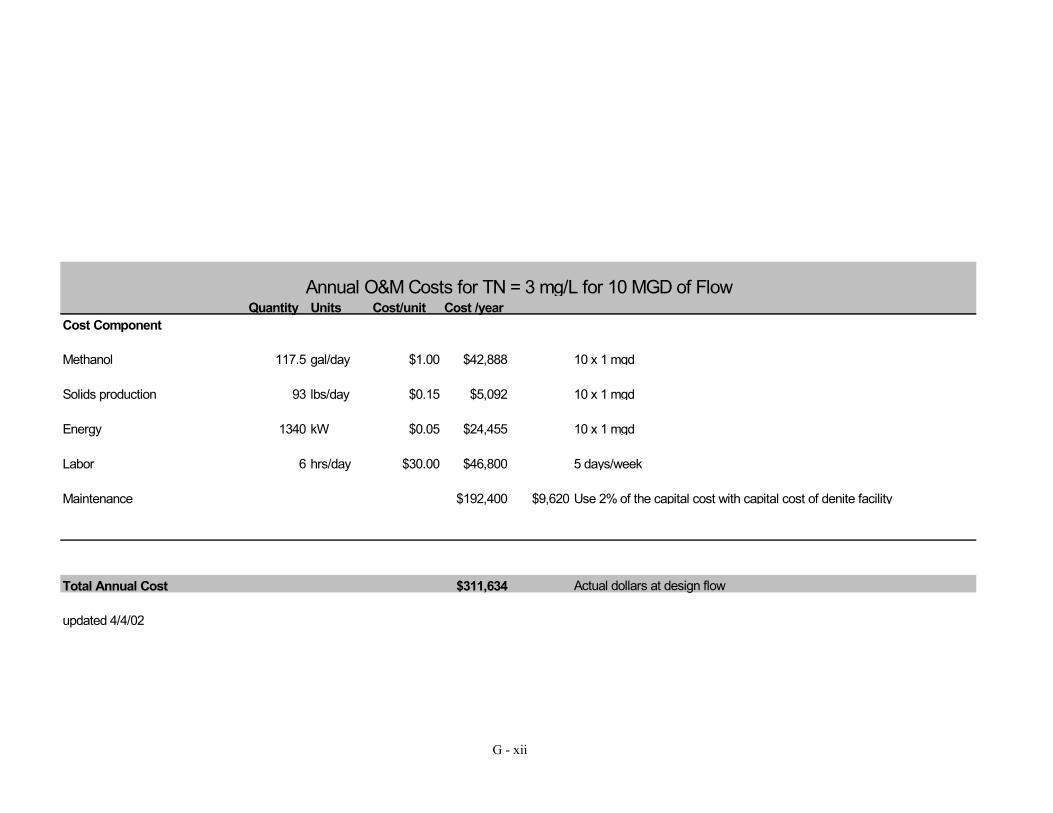
Quantity Units Cost/unit Cost /yearCost Component
Methanol 117.5 gal/day $1.00 $42,888 10 x 1 mgd
Solids production 93 lbs/day $0.15 $5,092 10 x 1 mgd
Energy 1340 kW $0.05 $24,455 10 x 1 mgd
Labor 6 hrs/day $30.00 $46,800 5 days/week
Maintenance $192,400 $9,620 Use 2% of the capital cost with capital cost of denite facility
Total Annual Cost $311,634 Actual dollars at design flow
updated 4/4/02
Annual O&M Costs for TN = 3 mg/L for 10 MGD of Flow
G - xii
Quantity Units Cost/unit Cost /yearCost Component
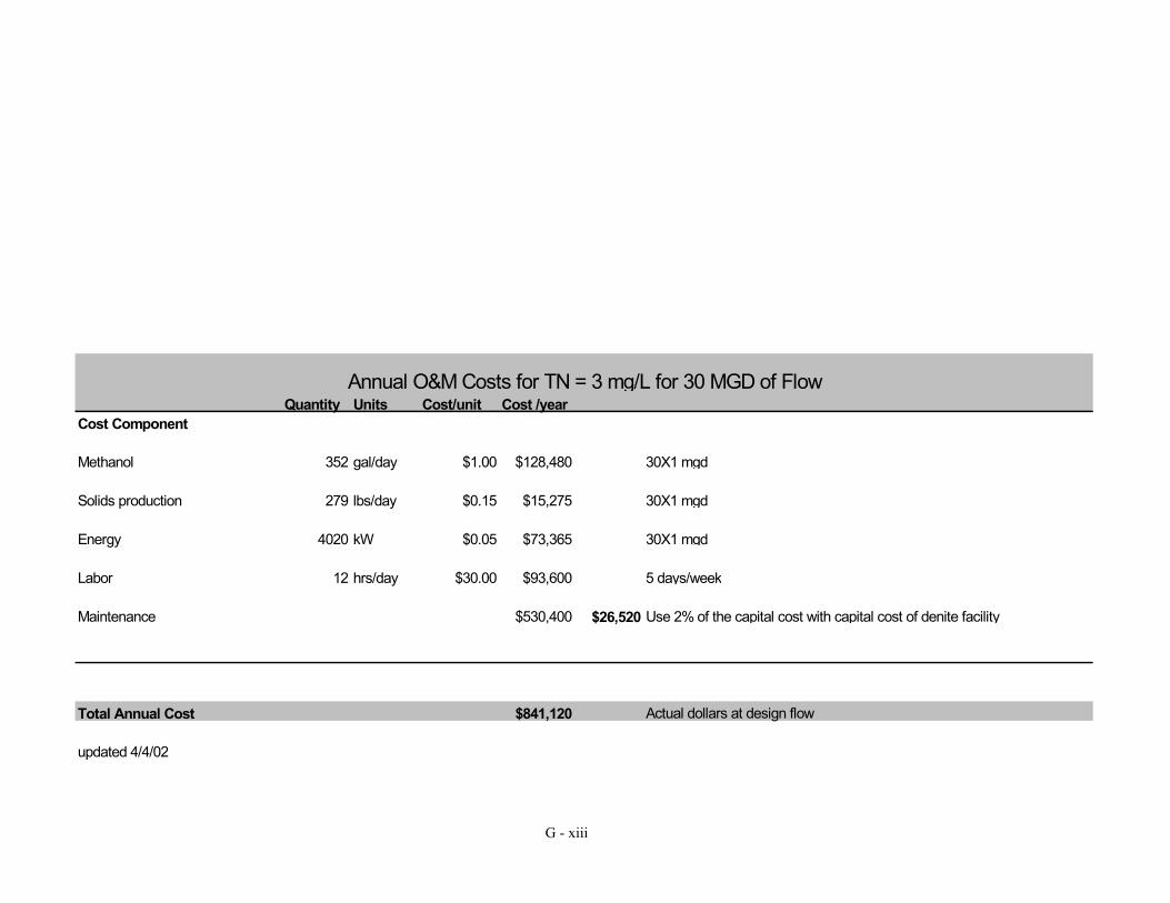
Methanol 352 gal/day $1.00 $128,480 30X1 mgd
Solids production 279 lbs/day $0.15 $15,275 30X1 mgd
Energy 4020 kW $0.05 $73,365 30X1 mgd
Labor 12 hrs/day $30.00 $93,600 5 days/week
Maintenance $530,400 $26,520 Use 2% of the capital cost with capital cost of denite facility
Total Annual Cost $841,120 Actual dollars at design flow
updated 4/4/02
Annual O&M Costs for TN = 3 mg/L for 30 MGD of Flow
G - xiii

Appendix H
References and Data Contacts for Industrial Costs: This appendix is organized by facility and available in hard copy by contacting Ning Zhou at the Bay Program Office, 410-295-6892 or [email protected]
H - i

Appendix I
Communications, Decisions, and References
for Cost and Load Data Compiling Part 1: Communications and Decisions for Cost Methodology Applications Part 2: Communications and Decisions for Load Calculations by Tier Part 3: References for Section X Summary Cost Tables
I - i

Part 1: Communications and Decisions for Cost Methodology Applications Attachment 1: Messages concerning the workgroup decision to use survey data for facilities >30MGD.
Marya Levelev
04/05/02 02:28 PM
To: [email protected], [email protected], [email protected], [email protected], [email protected], [email protected], [email protected], Allison Wiedeman/CBP/USEPA/US@EPA, Ning Zhou/CBP/USEPA/US@EPA, [email protected], [email protected], [email protected], [email protected], Ta-Shon Yu <[email protected]>, [email protected], [email protected], [email protected], [email protected]
cc: Subject: Re: facilities with design flow>30
Allison, for MD we would like to use cost curves for Back River and Patapsco. Western Branch already can achieve 3 mg/l. >>> <[email protected]> 04/05/02 12:21PM >>> hey folks - as we have agreed to in previous meetings, we will try to calculate costs for nrt for the larger facilities (= or greater than 30 MGD) individually based on site specific information where available, instead of using cost curves. Ning has assimilated a table below which lists all of the facilities in the watershed that are greater than 30, and has provided what data we have on them, whether it be the recent survey data, randall data, grant data, or info from MDE, or directly from the facility. Note that we could use info for some of them. in particular: Tashon - why did you not include a cost for western branch to go to 3 on your original cost spread sheets?? Bob E. or Tanya - can you see if you can get capital costs to go to 3 for the following facilities - we did not receive surveys from them, or they did not provide this information arlington richmond henrico county hrsd-vip hrsd nansemond hopewell - i believe that bob stiedel said that it is not feasible to even consider going to 3 for hopewell at this time. Allison Wiedeman 410-267-5733 [email protected] 410-267-5777 (f) Chesapeake Bay Program Office
I - ii
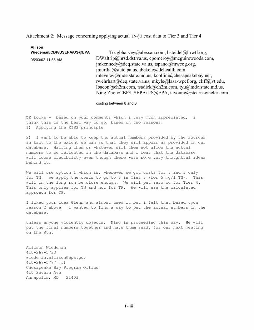
Attachment 2: Message concerning applying actual TN@3 cost data to Tier 3 and Tier 4 Allison
Wiedeman/CBP/USEPA/US@EPA
05/03/02 11:55 AM
To: [email protected], [email protected], [email protected], [email protected], [email protected], [email protected], [email protected], [email protected], [email protected], [email protected], [email protected], [email protected], [email protected], [email protected], [email protected], [email protected], Ning Zhou/CBP/USEPA/US@EPA, [email protected] costing between 8 and 3
OK folks - based on your comments which i very much appreciated, i think this is the best way to go, based on two reasons: 1) Applying the KISS principle 2) I want to be able to keep the actual numbers provided by the sources in tact to the extent we can so that they will appear as provided in our database. Halfing them or whatever will then not allow the actual numbers to be reflected in the database and i fear that the database will loose credibility even though there were some very thoughtful ideas behind it. We will use option 1 which is, wherever we got costs for 8 and 3 only for TN, we apply the costs to go to 3 in Tier 3 (for 5 mg/l TN). This will in the long run be close enough. We will put zero cc for Tier 4. This only applies for TN and not for TP. We will use the calculated approach for TP. I liked your idea Glenn and almost used it but i felt that based upon reason 2 above, i wanted to find a way to put the actual numbers in the database. unless anyone violently objects, Ning is proceeding this way. He will put the final numbers together and have them ready for our next meeting on the 8th. Allison Wiedeman 410-267-5733 [email protected] 410-267-5777 (f) Chesapeake Bay Program Office 410 Severn Ave Annapolis, MD 21403
I - iii
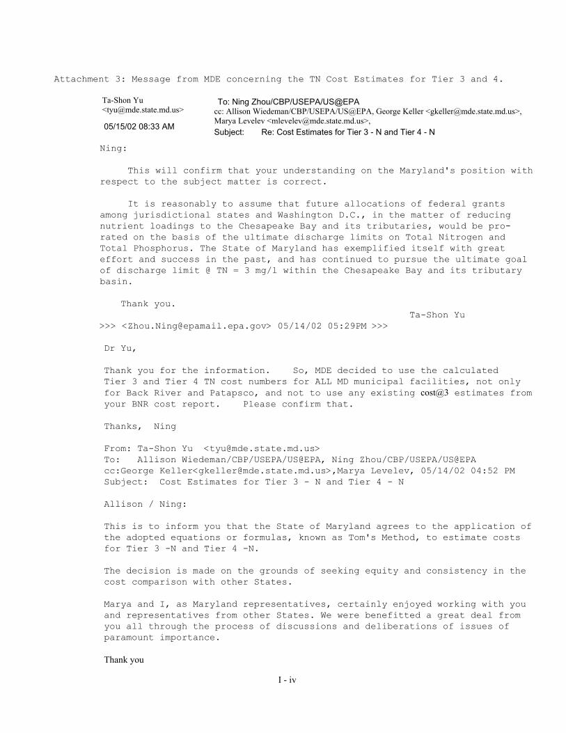
Attachment 3: Message from MDE concerning the TN Cost Estimates for Tier 3 and 4.
Ta-Shon Yu <[email protected]>
05/15/02 08:33 AM
To: Ning Zhou/CBP/USEPA/US@EPA cc: Allison Wiedeman/CBP/USEPA/US@EPA, George Keller <[email protected]>, Marya Levelev <[email protected]>, Subject: Re: Cost Estimates for Tier 3 - N and Tier 4 - N
Ning: This will confirm that your understanding on the Maryland's position with respect to the subject matter is correct. It is reasonably to assume that future allocations of federal grants among jurisdictional states and Washington D.C., in the matter of reducing nutrient loadings to the Chesapeake Bay and its tributaries, would be pro-rated on the basis of the ultimate discharge limits on Total Nitrogen and Total Phosphorus. The State of Maryland has exemplified itself with great effort and success in the past, and has continued to pursue the ultimate goal of discharge limit @ TN = 3 mg/l within the Chesapeake Bay and its tributary basin.
Thank you. Ta-Shon Yu
>>> <[email protected]> 05/14/02 05:29PM >>>
Dr Yu, Thank you for the information. So, MDE decided to use the calculated Tier 3 and Tier 4 TN cost numbers for ALL MD municipal facilities, not only for Back River and Patapsco, and not to use any existing cost@3 estimates from your BNR cost report. Please confirm that. Thanks, Ning From: Ta-Shon Yu <[email protected]> To: Allison Wiedeman/CBP/USEPA/US@EPA, Ning Zhou/CBP/USEPA/US@EPA cc:George Keller<[email protected]>,Marya Levelev, 05/14/02 04:52 PM Subject: Cost Estimates for Tier 3 - N and Tier 4 - N Allison / Ning: This is to inform you that the State of Maryland agrees to the application of the adopted equations or formulas, known as Tom's Method, to estimate costs for Tier 3 -N and Tier 4 -N. The decision is made on the grounds of seeking equity and consistency in the cost comparison with other States. Marya and I, as Maryland representatives, certainly enjoyed working with you and representatives from other States. We were benefitted a great deal from you all through the process of discussions and deliberations of issues of paramount importance. Thank you
I - iv

Appendix I. Part 2: Communications and Decisions for Load Calculations by Tier
Attachment 1: Message concerning the TN concentrations for Hopewell
Bob Steidel <[email protected]>
03/11/02 02:27 PM Please respond to Bob Steidel
To: "Ehrhart,Bob" <[email protected]>, Allison Wiedeman/CBP/USEPA/US@EPA
cc: Erika Bailey <[email protected]>, Bill M'Coy <[email protected]>, "Kennedy,John" <[email protected]>, Mark Haley <[email protected]>
Subject: Re: loads for tier 1 Allison: we will support our DEQ colleagues on this issue: 21.0 mg/ L TN performance for Tier 1 and 8.0 mg/L TN performance for Tier 2. And as Bob stated, we will provide very clear information to break out the cost for further evaluation. Bob Robert C. Steidel Environmental Manager Hopewell Regional Wastewater Treatment Facility, Virginia 231 Hummel Ross Road, P.O. Box 969 Hopewell, Virginia 23860 804-541-2210 804-541-2441 (fax) [email protected] ----- Original Message ----- From: "Ehrhart,Bob" <[email protected]> To: <[email protected]> Cc: <[email protected]>; "Kennedy,John" <[email protected]> Sent: Monday, March 11, 2002 1:43 PM Subject: loads for tier 1 Alison, I spoke w/ both John & Bob Steidel. In speaking w/ Bob Steidel, he stated that in 2004 the HRWWTF will include a written commitment to achieve 8.0 mg/l TN by 2010 either thru a voluntary or permit based action; this would seem to further align itself w/ the tier 2 definition. He also indicated cost to go from 21.0 mg/l to 8.0 mg/l could be easily broken out for which ever tier they are assigned. Given the fact the current grant and "level of effort" both reflect 21.0 mg/l, we suggest that tier one be based on 21.0 mg/l TN and that tier 2 be based on 8.0 mg/l TN, which reflects the tier 2 definition - "mix of regulatory and voluntary programs" and "motivated by incentives". Thus, assigning 21.0 mg/l for tier 1 and the current level of effort/cost, followed by the escalating cost to "reach and maintain" 8.0 mg/l for TN of tier 2 seems to be the most appropriate scenario. However, as long as it is recorded that the Bay office and the owner (HRWWTF) are comfortable/agreeable w/ 8.0 mg/l TN for tier 1, we do not object to 8.0 mg/l being assigned to tier 1.
I - v

Bob Ehrhart DEQ-Chesapeake Bay Program 804-698-4466 [email protected] http://www.deq.state.va.us/bay/wqif.html -----Original Message----- From: [email protected] [SMTP:[email protected]] Sent: Monday, March 11, 2002 10:44 AM To: Ehrhart,Bob Cc: [email protected]; Kennedy,John Subject: Re: loads for tier 1 Bob - there can be an argument for both, however, i feel compelled to go with what the facility operators say,. Can you live with 8 mg/l for tier 1?? Allison Wiedeman 410-267-5733 [email protected] 410-267-5777 (f) Chesapeake Bay Program Office 410 Severn Ave Annapolis, MD 21403 "Ehrhart,Bob" <[email protected]> To: Allison Wiedeman/CBP/USEPA/US@EPA, Bob Steidel <[email protected]>,"Kennedy,John" <[email protected]> 03/11/02 08:46 AM cc: Subject: loads for tier 1 Allison/Bob, Would it not be better and/or more reflective of the current situation to show Hopewell as 21.0 mg/l TN for tier 1 & 8.0 mg/l for tier 2? The 21.0 mg/l is consistent w/ the existing grant agreement and commitment level; the 8.0 mg/l for tier 2 is consistent and shown for other localities (such as Petersburg, Falling Creek, etc.). Thus, I suggest tier 1 be 21.0 mg/l and tier 2 be 8.0 mg/l for Hopewell. Bob Ehrhart DEQ-Chesapeake Bay Program 804-698-4466 [email protected] http://www.deq.state.va.us/bay/wqif.html
I - vi

Attachment 2: Message for 2010 Flow of Hopewell:
Allison Wiedeman
09/25/02 12:57 PM Subject:Re: Hopewell Flows
To:"Ehrhart,Bob" <[email protected]> cc: Bob Steidel <[email protected]>, "Kennedy,John" <[email protected]>, "HaleyMark (E-mail)" <[email protected]>, Ning Zhou/CBP/USEPA/US@EPA
Bob, Mark Haley and I discussed the flow issue. We determined that it is most appropriate to use a 2010 flow projection of 35.12 MGD. This flow comes from the average flow used in their 1995 - 2000 permit. Even though the current 2000 - 2005 permit uses an average flow of about 29 MGD, Mark believed it is more realistic to use a flow from the previous permit to estimate 2010 flows. WE need to note in the cost report, however, that this flow could go beyond 35.12 due to regional cooperation and economic development in the area. Remember that this flow will only be used for load estimation purposes, and the 50 MGD will be used for costing purposes.
Allison Wiedeman 410-267-5733 [email protected] 410-267-5777 (f) Chesapeake Bay Program Office 410 Severn Ave Annapolis, MD 21403
"Ehrhart,Bob" <[email protected]>
08/26/02 08:10 AM Subject: Hopewell Flows
To:Bob Steidel <[email protected]>, Allison Wiedeman/CBP/USEPA/US@EPA, Ning Zhou/CBP/USEPA/US@EPA cc: "HaleyMark (E-mail)" <[email protected]>, "Kennedy,John" <[email protected]>
Well, I hope this email will bring clarity and resolution to the aspects of flow w/ respect to the NRT cost analysis. As I see it, there are two distinct issues summarized as follows. 1) Design flow - This POTW has a design flow of 50 MGD; the current upgrade for NRT to 21.0 mg/l for TN is based on the design flow. Any future installation of NRT to meet an annual average of 8.0 mg/l would probably also be based on the current design flow (use of the design flow is consistent with other WQIF projects, such as ASA, Mooney, Noman-Cole, Henrico). 2) 2010 flow- For the purpose of determining loads, this flow is independent of the design flow and is based on flows projected to be discharging (and/or equivalent to the current industrial flow) in the year 2010 . In all municipal facilities (such as the facilities listed in item #1, UOSA, etc.), the 2010 flow used for estimating the load is considerably less than the design flow (for facilities listed in item #1, the 2010 flow ranged from 63 to 87% of the design flow w/ the larger increases generally in NoVA).
I - vii
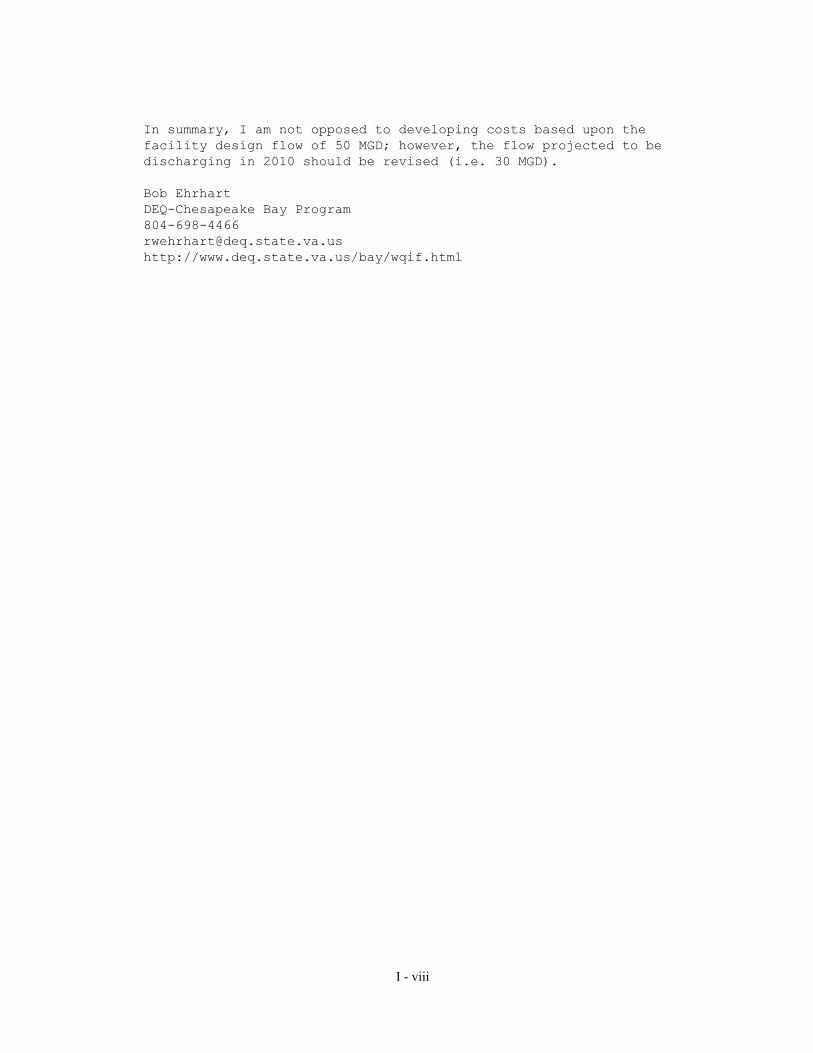
In summary, I am not opposed to developing costs based upon the facility design flow of 50 MGD; however, the flow projected to be discharging in 2010 should be revised (i.e. 30 MGD). Bob Ehrhart DEQ-Chesapeake Bay Program 804-698-4466 [email protected] http://www.deq.state.va.us/bay/wqif.html
I - viii

Attachment 3: 2010 Flows: Broad Run Water Reclamation Facility
03/07/02 01:41 PM
To:Allison Wiedeman/CBP/USEPA/US@EPA cc: [email protected], [email protected],
[email protected] Subject:2010 Flows: Broad Run Water Reclamation Facility
Allison: As we just discussed, the name of the facility to be added to "Table 2: New Facilities by 2010" of the report entitled "Data Compiling Description for Revised 2005 and 2010 Scenarios" (February 1, 2001) is the Broad Run Water Reclamation Facility in Loudoun County, Va. 2010 flow is currently projected at 2.4 mgd. Christopher D. Pomeroy McGuireWoods LLP One James Center 901 East Cary Street Richmond, Virginia 23219 804.775.1028 (Direct Line) 804.698.2246 (Direct FAX) [email protected]
I - ix

Attachment 4: 2010 flow projections for Ashland, Doswell [email protected]
03/11/02 01:59 PM
To:Allison Wiedeman/CBP/USEPA/US@EPA cc:Ning Zhou/CBP/USEPA/US@EPA,
[email protected] Subject:RE: 2010 Flows: Broad Run Water Reclamation
Facility
Allison:
For the Hanover County, VA plants:
1. Totopotomoy shows no flow for 2005. The flow should be 2.5 mgd.
2. Ashland should be 1.4 mgd in 2005 and 1.55 in 2010.
3. Doswell is a special case. It is a combined discharged point for the Doswell WWTP effluent and the Bear Island paper mill effluent. The paper mill has a right to 5.75 mgd. You may need to take this into account with planning industry controls. The flows should be 6.75 mgd for both 2005 and 2010, unless for some reason Bear Island won't be using that capacity.
Chris
I - x

Attachment 5: Message for 2010 flow of H. L. Mooney Steve Bennett
03/12/02 05:36 PM
To: Allison Wiedeman/CBP/USEPA/US@EPA, Ning Zhou/CBP/USEPA/US@EPA cc: Subject: FW: Flow Projection
Allison and Ning, Dave Waltrip and I have not connected. I need you help. Did you get flow projections for the H. L. Mooney WWTP in Prince William County? WashCOG should have forwarded them as well as Waltrip. If you don't have them, they are: Year Flow 2005 12.130 MGD 2010 14.630 MGD Please let me know if you did not get them, ok? Thanks. STEVE BENNETT
I - xi

Attachment 6: Message for Henrico 2010 Flow [email protected].
va.us (Robert W. Ehrhart)
02/06/02 04:18 PM Please respond to rwehrhart
To: Ning Zhou/CBP/USEPA/US@EPA, Allison Wiedeman/CBP/USEPA/US@EPA
cc:[email protected] (John M. Kennedy) Subject: Henrico Flows (Final)
Ning, To summarize our conversation, the facility master plan completed in 1997 projected the WWTF to be operating at about 65 MGD in 2010 (per Keith Cramer). However, the economy - including housing starts and the semiconductor industry driving the rapid growth in Eastern Henrico - have slowed drastically. Pump station flows which would have driven the high daily flows are also not materializing and they could be delayed until 2012-15. I also spoke with one of the design engineers working for the County & he does not believe the flow level of 65 MGD will occur by 2010. So in summary for the 2010 run, we suggest that a flow of 50 MGD be used as a compromise between the population projection method and the 1997 Facility Plan. With that revision in mind, I also suggest flow allocations of 89% for Henrico Co., 10% for Hanover Co., and 1% for Goochland Co. in 2010. Flow allocations of 86% for Henrico, 13% for Hanover, and 1% for Goochland were previously suggested for the 2000 run. Bob Ehrhart DEQ-Chesapeake Bay Program 804-698-4466 804-698-4116 (fax) [email protected] http://www.deq.state.va.us/bay
I - xii

Attachment 7: Message for 2010 flow of majors plants around DC area
Tanya Spano <[email protected]>
03/13/02 12:01 PM
To:Ning Zhou/CBP/USEPA/US@EPA cc:Timothy Murphy <[email protected]>, Mukhtar Ibrahim
<[email protected]> Subject:Updated Flow Projections for COG Region's Major WWTPs
Ning, Attached is an Excell table with updated flow projections for our major plants. Thanks for working with us on this. Call if you have any questions. Tanya
<<CBPvsCOGflow projections.final.031302.xls>> CBP COG CBP Jursidiction CBP Jurisdiction
FACILITY NPDES 2000 Flow 2000 Flow 2005 Flow 2005 Flow 2010 Flow 2010 FlowMGD MGD MGD MGD MGD MGD
BOWIE MD0021628 1.903 1.903 2.002 2.086
PARKWAY MD0021725 5.962 5.966 6.271 6.200 6.536 6.200
WESTERN BRANCH MD0021741 18.293 18.301 19.241 21.000 20.054 23.000
ALEXANDRIA VA0025160 36.824 36.842 37.384 37.384 37.943 37.943
AQUIA VA0060968 3.326 3.327 3.542 3.758
ARLINGTON VA0025143 27.464 27.467 27.699 33.570 27.934 35.290
BALLENGER CREEK MD0021822 3.437 3.440 3.785 4.120
BELTSVILLE USDA EAST MD0020842 0.215 0.215 0.226 0.236
BELTSVILLE USDA WEST MD0020851 0.113 0.113 0.119 0.124
BLUE PLAINS DC0021199 317.899 317.948 333.619 330.920 348.486 341.710
DALE CITY #1 VA0024724 2.561 2.546 2.811 3.061
DALE CITY #8 VA0024678 2.382 2.383 2.615 2.847
DAMASCUS MD0020982 0.881 0.892 0.927 0.840 0.974 0.860
FORT DETRICK MD0020877 0.924 0.969 1.018 1.108
H.L. MOONEY VA0025101 9.632 9.633 10.572 12.130 11.513 14.630
LEESBURG MD0066184 2.677 2.678 2.817 2.958
MATTAWOMAN MD0021865 7.058 7.052 7.612 8.172
NOMAN M. COLE JR. VA0025364 42.889 42.893 44.859 46.670 46.828 53.000
PISCATAWAY MD0021539 21.052 21.062 22.144 24.200 23.080 25.300
POOLESVILLE MD0023001 0.601 0.593 0.632 0.664
PURCELLVILLE VA0022802 0.352 0.353 0.388 0.424
QUANTICO-MAINSIDE VA0028363 1.159 1.159 1.272 1.385
SENECA CREEK MD0021491 6.494 6.492 6.835 17.100 7.177 18.800
UPPER OCCOQUAN VA0024988 24.391 24.398 25.511 29.500 26.631 34.000
TOTAL 512.330 512.455 536.388 532.314 559.423 561.533NOTE: Yellow colored raws indicate projected flow was not verifiedUse jurisdictions flow for all WWTPs except for Alexandria. ASA agreed to use of CBP projected flows.
Some wastewater flows in the Blue Plains service area are now off-loaded to the Seneca Creek wwtp. The quantity of diverted flow will increase significantly in the future as the Seneca wwtp expands. Both Blue Plains wwtp and Seneca Creek wwtp projected flows have been adjusted to reflect those changes.
I - xiii

Attachment 8: 2010 Flow Projection from HRSD revised by VADEQ
Chesapeake Bay Program
Flow Projections for HRSD Facilities
The attached table provides flow projections currently being used for treatment plants in Virginia. These projections are based upon the local planning associated with each of these facilities and provide more accurately projected 2010 flows than the existing EPA data as they take into account know industrial and residential development as well as planned service area expansion. I am most familiar with the HRSD projections and offer the following information to explain these projections.
HRSD has provided flow projection data from our 1990 development plan. All of these projections
are expected to change within the next two months with the completion of our 2002 development plan. Furthermore it should be noted that our multiple treatment facilities are tied together allowing flow to be diverted between treatment plants. As a result no single plant flow projection will ever be accurate although the total flow for HRSD should be a reasonably accurate estimate as discussed below.
HRSD currently serves seventeen localities in southeastern Virginia with thirteen regional
wastewater treatment plants. Being a regional utility, none of our facilities are necessarily intended to treat the wastewater flows from any one locality. They are all regional facilities and handle flows from several localities. In fact, one of the strengths of our system is that we can actually divert flows from one facility to another. This can even mean diverting wastewater flows from one river basin to another.
On the previous page, we laid out the projected 2005 – 2010 flows from our 1990 Development
Plan. Some of these flows are higher than those projected in the Chesapeake Bay Program figures and some are actually lower. This is due mainly to the fact discussed above, where flows can be diverted between facilities to best utilize the assets that we have available, thus delaying the need for treatment plant expansions. We are currently in the process of updating our development plan and anticipate having new flow projections within the next couple of months. When those projections are done, we will forward a copy of the most up to date projections for all of our facilities. Also note that the four treatment plants on the Middle Peninsula are currently planned to be piped into our York River Plant in the future.
Because of these diversion capabilities within HRSD’s system, we would like to suggest that a
“bubble” be created grouping the plants together that are within the different major watersheds going into the bay. We would suggest that all of our plants fall within either the James River or York River basins. The York River Basin would include our King Williams Plant, Matthews Plant, Urbana Plant, West Point Plant and York River Plant. The James River Basin would include our Army Base Plant, Boat Harbor Plant, Chesapeake-Elizabeth Plant, James River Plant, Nansemond Plant Williamsburg Plant and VIP Plant. Using our 1990 Development Plan flows and recent estimates for Middle Peninsula Plants, we would suggest that the total flows for the York River system would be 13.185 MGD, and total flows for the James River system would be 158.75 MGD. In our 1990 Development Plan, we had envisioned diverting flows
I - xiv

away from our York River Plant to the James River Plant to avoid expanding the York River Treatment Plant until a later date. We are reevaluating that as part of our current development plan work and may request that those flows be reallocated back towards the York River Wastewater Treatment Plant.
We appreciate the effort that it takes to make all the flow projections necessary for the Chesapeake
Bay Program efforts. Again, because of the strengths and the flexibility of being able to divert flows between wastewater treatment plants, it is recommended that the Chesapeake Bay Program adopt a “bubble” methodology that would allow HRSD to group our plants into these two river basins as discussed above. We recognize that the Chesapeake bay program is operating with a deadline that does not allow waiting until data updates can be completed. We would however request that EPA note that the numbers provided are based upon a 12 year old analysis and that new more accurate numbers will be available by the end of May. Both the newer numbers and the bubble approach should be used any HRSD load allocation that ultimately is developed as a result of this process.
I - xv

CBP_BASIN FACILITY NPDES 98Flow 99Flow 00Flow 05Flow 10FlowJAMES RIVER
HRSD-ARMY BASE VA0081230 12.519 13.000 12.749 17.250 17.450
JAMES RIVER
HRSD-BOAT HARBOR VA0081256 14.825 14.885 14.318 22.500 23.050
JAMES RIVER
HRSD-CHESAPEAKE/ELIZABETH VA0081264 20.112 20.265 19.056 25.530 26.300
JAMES RIVER
HRSD-JAMES RIVER VA0081272 15.475 14.436 14.467 21.280 20.00
JAMES RIVER
HRSD-NANSEMOND VA0081299 17.098 19.400 18.948 18.980 20.150
JAMES RIVER
HRSD-PINNERS POINT (PORTSMOUTH)
VA0025003
JAMES RIVER
HRSD-VIP VA0081281 33.716 33.182 31.535 35.700 35.900
JAMES RIVER
HRSD-WILLIAMSBURG VA0081302 12.261 13.077 15.344 12.700 15.900
JAMES RIVER
HENRICO COUNTY VA0063690 38.659 34.045 37.096 57.000 65.000
JAMES RIVER
LYNCHBURG VA0024970 13.609 13.012 13.216 17.400 17.400
JAMES RIVER
PETERSBURG VA0025437 12.563 12.111 12.035 11.950 12.930
RAPPAHANNOCK RIVER
LITTLE FALLS RUN VA0076392 2.475 2.271 2.618 3.300 4.160
RAPPAHANNOCK RIVER
URBANNA VA0026263 0.044 0.047 0.056 0.081 0.113
YORK RIVER HRSD-YORK VA0081311 10.663 10.868 11.329 11.980 12.700YORK RIVER MATHEWS COURTHOUSE VA0028819 0.051 0.044 0.047 0.060 0.080YORK RIVER WEST POINT VA0075434 0.605 0.543 0.623 0.644 0.600YORK RIVER KING WILLIAM VA0088102 0.042 0.050
POTOMAC RIVER
AQUIA VA0060968 3.731 3.202 3.326 4.210 5.290
POTOMAC RIVER
FISHERSVILLE VA0025291 1.294 0.717 0.798 1.520 1.710
POTOMAC RIVER
HARRISONBURG-ROCKINGHAM (NORTH RIVER REGIONAL)
VA0060640 10.671 8.973 8.571 10.630 11.650
POTOMAC RIVER
MIDDLE RIVER VA0064793 5.393 3.599 3.597 5.100 5.650
POTOMAC RIVER
NOMAN M. COLE JR. POLLUTION CONTROL PLANT
VA0025364 45.257 41.616 42.889 47.000 53.000
POTOMAC RIVER
STUARTS DRAFT VA0066877 1.187 0.767 0.836 1.150 1.500
POTOMAC RIVER
UPPER OCCOQUAN SEWAGE AUTHORITY
VA0024988 24.114 23.684 24.391 29.500 34.000
POTOMAC RIVER
WEYERS CAVE STP VA0022349 0.116 0.360 0.400
I - xvi
Attachment 9: Message concerning 2010 flow for Moores Creek.
"Waltrip, David" <[email protected]>
03/11/02 04:55 PM
To:Ning Zhou/CBP/USEPA/US@EPA cc: Subject:FW: Moores Ck WWTP flows
I just returned to my office and received the following e-mail. These are minor changes but I though I would give you the chance to incorporate these values if you have not yet started the run. If you already have started the run well change is so small it likely will not change anything. G. David Waltrip -----Original Message----- From: Potter, Eugene Sent: Monday, March 11, 2002 9:35 AM To: Waltrip, David Subject: Moores Ck WWTP flows Dave. I have reviewed subject flows and w/o knowing how DEQ made their projections, would offer the following projections for Moores Ck based on 20 years of data and least squares averaging: 2005 11.433 MGD 2010 11.888 MGD Not too different from the DEQ numbers, but probably better numbers.
I - xvii
Attachment 10: Message concerning 2010 flow for Patapsco
Marya Levelev <[email protected]>
03/13/02 04:32 PM
To: Ning Zhou/CBP/USEPA/US@EPA cc: George Keller <[email protected]>, Jeff Rein <[email protected]> Subject: Re: McKenny BNR By 2010?
Ning, Sorry. We should use 73 mgd for Patapsco. >>> <[email protected]> 03/13/02 03:04PM >>> Marya, Thank you! We will use the design flow of 63 for patapsco for 2010. Ning Marya Levelev <[email protected]> To: Ning Zhou/CBP/USEPA/US@EPA cc: Jeff Rein <[email protected]> Subject: Re: McKenny BNR By 2010? 03/13/02 02:44 PM There are currently no plans for Mckenny. We should not consider it. For Patapsco we could use as high as 70 mgd or at least 63 –design capacity. Even though Baltimore City may not show growth, Patapco serves more than one jurisdiction: Howard County, Baltimore County. Arundel County. Flow may increase as a result of growth there. Let me know if you need additional information. Thanks >>> <[email protected]> 03/12/02 05:27PM >>> Marya, We do not have BNR status for McKenny. Should we put it as BNR by 2010 for it? Thanks, Ning
I - xviii

Attachment 11: Blue Plain Flow Allocation Rate from MWCOG
Chesapeake Bay Program Bay-wide Use Attainability Analysis
Cost Allocation Methodology for the Blue Plains Wastewater Treatment Plant COG staff document (Approved by BPTC, 4/14/02) Capital Costs Allocate the estimated capital costs for each Tier based on the IMA’s 370 MGD wastewater flow allocations because that is how capital costs are allocated to the jurisdictions. However, for the non-signatory jurisdictions (i.e., Potomac Interceptor Users), their share of the capital costs would be attributed to the District rather than the individual states as DC-WASA pays those capital costs and works out payment with those non-signatory parties according to individual service agreements. O&M Costs Allocate the estimated O&M costs for each Tier based on the projected flows from each of the jurisdictions using the latest BPSA flow projections. For the non-signatory jurisdictions (i.e., Potomac Interceptor Users), use the BPSA 2010 flow projections and attribute their O&M costs to the respective state – using the same protocol used to allocate Blue Plains’ nutrient loads for the CBP and states. These wastewater flows are based on the projections from COG’s Cooperative Forecast Round 6.2 (6/25/01 run), updated to reflect known flow management impacts through 2025 (4/9/02 update).
ALLOCATIONS CAPITAL COSTS
(IMA-based Flows) O&M COSTS (2010 BPSA Adj. Flows)
JURISDICTION Flows (MGD)
% Costs Flows (MGD)
% Costs
Maryland WSSC 169.60 0.4584 129.43
Naval Ship R&D & NPS* 0.040 MD subtotal 169.60 0.4584 129.47 0.3819 Virginia
Fairfax Co. (& Arlington Co.)
31.00 0.0838 31.00
LCSA* 13.80 Vienna* 1.15
Dulles Airport* 1.05 VA subtotal 31.00 0.0838 47.00 0.1386 District
District & PI Users (*) subtotal
169.4 0.4578
District subtotal 162.54 0.4795
TOTAL 370.00 100.00 339.01 100.00
I - xix

Appendix I: Part 3: References for Section IX Summary Cost Tables The following references for the cost tables are available in hard copy by contacting Ning Zhou at the Chesapeake Bay Program Office, 410-295-6892 or [email protected] 1 = Calculated from the methodologies provided from Thor Young, Stearn & Wheler, LLC and Tom Sadick, CH2M
Hill. 2 = NRT eligible cost report from MDE,4/23/02, where cost=0, MDE has indicated funds already appropriated 2a = NRT Cost report, from MDE 3/6/2002 3 = Randall 51 Facility Report, 1999 for BNR @8 and additional 3/2001 report with 60 facilities. 4 = Paid for by Corp of Engineers 5 = From VA 2000 Annual Report and VA 2002 annual Report - Assumes that the cost share information equals
1/2 of total BNR cost to get 8, and that funds are already made available for these facilities to go to 8, except for FMC and Henrico where no funds have been spent as of 2002.
6 = Email from Bob Ehrhart to Allison Wiedeman, 3/7/02 7 = BNR funded under federal funds. 8 = No cost is applied, because TN or TP =current level for Tier 1for this facility 8a = The 2010 TP concentration of 1.5 mg/l shown for these facilities reflects the specific effluent concentration
targeted by Virginia either under WQIF Grant program and/or the Tributary Strategy Plan for the Lower River Tributaries.
9 = Cost survey from Seaford WWTP, 3/22/02 10 = From 4/2/01 letters from Eastern Snyder County Regional Authority to Senator Specter. Also, costs not
calculated to 8 because they are currently designing only to 3 (4/26/01 Telephone conversation between CBPO and Gannett Hemming)
11 = Message from WVDEP, cost=0 due to irrigation. 12 = Email message from Paul Janiga, DE DNREC, 3/28/02. 13 = Cost survey from Mike Kyle, LASA, 3/6/02 14 = C CSO & Blue Plains Cost Estimates- UAA cost analysis, from Tanya spano, WMCOG, 4/10/02 15 = Telephone conversation with Sunberry WWTP, 6/21/01 16 = Cost Summary: City of Hopewell, from Bob Steidel, Hopewell Regional Wastewater Treatment Facility.
8/7/2002. 17 = Message from Tanya Spano concerning Broad Run, 3/13/02 18 = Message from Marya Levelev, 4/5/02, Western Branch already can achieve 3 mg/l.
I - xx

19 = Message from Marya Levelev, 8/12/02, to add $10 million TN cc in Tier 2 for Back River 20 = Message from Bob Steidel, 9/17/02, to remove the Tier 1 cost for Hopewell. 21 = Message from Bob Ehrhart, 9/4/02, to remove Tier 1 costs for FMC and Hopewell. 22 = Message from Bob Ehrhart, 9/19/02, to add SIL which replaced Broadway Lagoons, Timberville, Rocco
Quality Foods and Wampler Foods-Timberville. 23 = Message from Bob Ehrhart, 11/14/02, No Tier 2 TP cost due to chemical feed facilities have been funded. A = The capital costs at TN =3 from sources other than calculation are applied to Tier 3 for TN. And, in these
cases, the Tier 4 TN capital costs are set to zero. Message from Allison Wiedeman, 5/3/02. B = The value is set to zero, because this plant's TN or TP level have been lower than the defined level in this
Tier for more than five years. C14 = Message from W. Hunley, HRSD, 10/3/02 C15 = Cost shown represent an order of magnitude planning level estimate as transmitted by HRSD on October 3,
2002. A less costly alternative, which provides for only seasonal nitrification and/or an annual average TN concentration greater than 8.0 mg/l, does potentially exist as discussed in the September 1989 Technical Memoranda C.22 and C. 25 prepared by CH2M Hill. Message from Bob Ehrhart, 11/4/02
C6 = Letter from City of Lynchburg to Allison Wiedeman, 7/14/2001 C9 = Bos, Robert E, PE, Public Utility Administrator with County of Stafford, letter to Allison Wiedeman, EPA, re:
Nitrogen Removal Costs, 7/31/01 M = For facilities with existing capital costs and no O&M costs available, the O&M costs are calculated from
exiting capital costs adjusted by the cost ratio between calculated O&M and capital cost from the methodologies provided from Thor Young, Stearn & Wheler, LLC and Tom Sadick, CH2M Hill.
N = NRT facilities that currently have or will install NRT by 2010, It is assumed that no additional cost is needed. S = From NRT cost survey results.
I - xxi