Appendix K - Mechanical Engineering · 40 000 45 000 50 000 0 2 500 5 000 7 500 10 000 12 500 15...
31
Transcript of Appendix K - Mechanical Engineering · 40 000 45 000 50 000 0 2 500 5 000 7 500 10 000 12 500 15...
Appendix K
Beckman JA-20 Data Sheet
The data sheet, including rpm vs G force graphs, for the centrifuge used for harvesting of bacteria is
found in the following pages.
234
J-TB-003AZNovember 2008
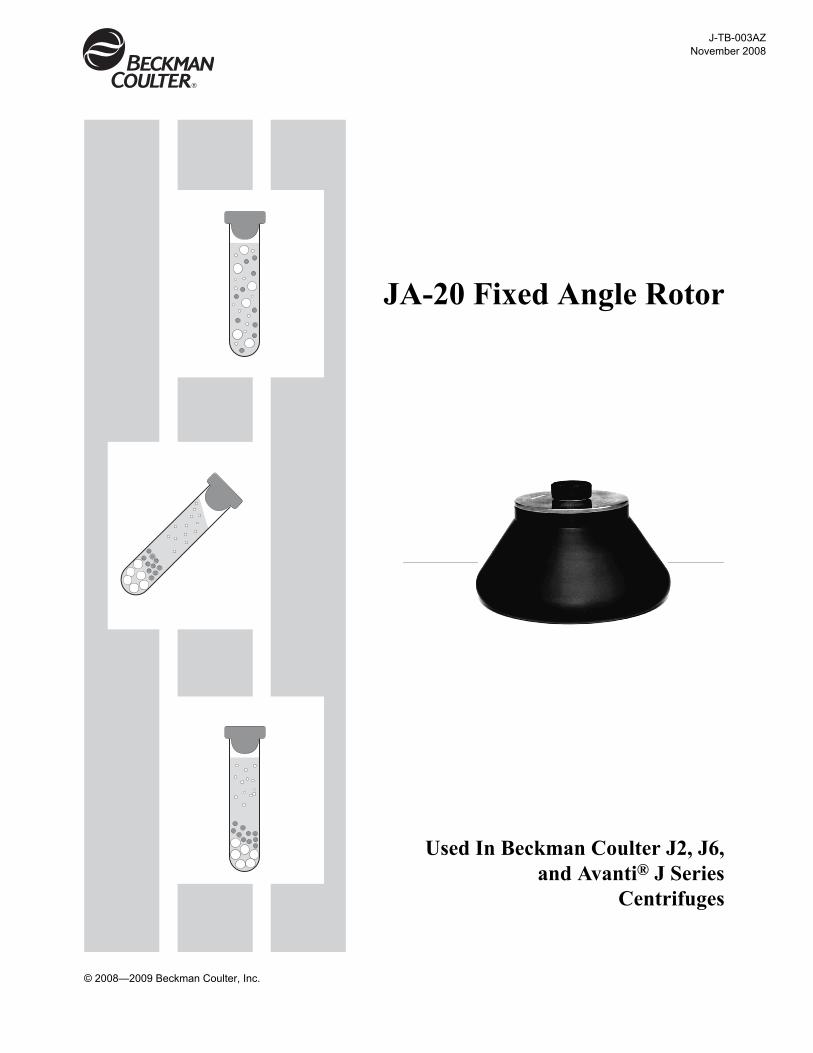
JA-20 Fixed Angle Rotor
Used In Beckman Coulter J2, J6,and Avanti® J Series
Centrifuges
© 2008—2009 Beckman Coulter, Inc.
2
JA-20 Rotor
SAFETY NOTICE
This safety notice summarizes information basic to the safe use of the rotor described in this manual. The international symbol displayed above is a reminder to the user that all safety instructions should be read and understood before operation or maintenance of this equipment is attempted. When you see the symbol on other pages throughout this publication, pay special attention to the specific safety informa-tion presented. Observance of safety precautions will also help to avoid actions that could damage or adversely affect the performance of the rotor. This rotor was developed, manufactured, and tested for safety and reliability as part of a Beckman Coulter centrifuge/rotor system. Its safety or reliability cannot be assured if used in a centrifuge not of Beckman Coulter’s manufacture or in a Beckman Coulter centrifuge that has been modified without Beckman Coulter’s approval.
Handle body fluids with care because they can transmit disease. No known test offers complete assurance that such fluids are free of micro-organisms. Some of the most virulent—Hepatitis (B and C) viruses, HIV (I–V), atypical mycobacteria, and certain systemic fungi —further emphasize the need for aerosol protection. Handle other infectious samples according to good laboratory procedures and methods to prevent spread of disease. Because spills may generate aerosols, observe proper safety precautions for aerosol contain-ment. Do not run toxic, pathogenic, or radioactive materials in this rotor without taking appropriate safety precautions. Biosafe containment should be used when Risk Group II materials (as identified in the World Health Organization Laboratory Biosafety Manual) are handled; materials of a higher group require more than one level of protection.
The rotor and accessories are not designed for use with materials capable of developing flammable or explosive vapors. Do not centrifuge such materials in nor handle or store them near the centrifuge.
Although rotor components and accessories made by other manufacturers may fit in the JA-20 rotor, their safety in this rotor cannot be ascertained by Beckman Coulter. Use of other manufacturers’ components or accessories in the JA-20 rotor may void the rotor warranty and should be prohibited by your laboratory safety officer. Only the components and accessories listed in this publication should be used in this rotor.
Make sure that filled containers are loaded symmetrically into the rotor and that opposing tubes are filled to the same level with liquid of the same density.
If disassembly reveals evidence of leakage, and pathogenic or radioactive materials are involved, you should assume that some fluid escaped the rotor. Apply appropriate decontamination procedures to the centrifuge and accessories.
Never exceed the maximum rated speed of the rotor and labware in use. Refer to the section on RUN SPEEDS.
Do not use sharp tools on the rotor that could cause scratches in the rotor surface. Corrosion begins in scratches and may open fissures in the rotor with continued use.
!
!
!
!
!
!
!
!
3
* Relative Centrifugal Field (RCF) is the ratio of the centrifugal acceleration at a specified radiusand speed (rZ2) to the standard acceleration of gravity (g) according to the following formula:
where r is the radius in millimeters, Z is the angular velocity in radians per second(2 S RPM /60), and g is the standard acceleration of gravity (9807 mm/s2). After substitution:
RCF rZ2
g---------=
RCF 1.12 r RPM1000------------© ¹§ · 2
=
JA-20 Rotor
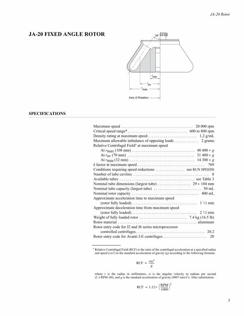
JA-20 FIXED ANGLE ROTOR
SPECIFICATIONS
Maximum speed . . . . . . . . . . . . . . . . . . . . . . . . . . . . . . . . . . . . 20 000 rpmCritical speed range*. . . . . . . . . . . . . . . . . . . . . . . . . . . . . . 600 to 800 rpmDensity rating at maximum speed. . . . . . . . . . . . . . . . . . . . . . . . . 1.2 g/mLMaximum allowable imbalance of opposing loads. . . . . . . . . . . . . 2 gramsRelative Centrifugal Field† at maximum speed
At rmax (108 mm) . . . . . . . . . . . . . . . . . . . . . . . . . . . . . . . . 48 400 u gAt rav (70 mm) . . . . . . . . . . . . . . . . . . . . . . . . . . . . . . . . . . 31 400 u gAt rmin (32 mm) . . . . . . . . . . . . . . . . . . . . . . . . . . . . . . . . . 14 300 u g
k factor at maximum speed . . . . . . . . . . . . . . . . . . . . . . . . . . . . . . . . . . 769Conditions requiring speed reductions . . . . . . . . . . . . . . . see RUN SPEEDSNumber of tube cavities . . . . . . . . . . . . . . . . . . . . . . . . . . . . . . . . . . . . . . 8Available tubes . . . . . . . . . . . . . . . . . . . . . . . . . . . . . . . . . . . . . . see Table 3Nominal tube dimensions (largest tube) . . . . . . . . . . . . . . . . . 29 u 104 mmNominal tube capacity (largest tube) . . . . . . . . . . . . . . . . . . . . . . . . 50 mLNominal rotor capacity . . . . . . . . . . . . . . . . . . . . . . . . . . . . . . . . . . 400 mLApproximate acceleration time to maximum speed
(rotor fully loaded) . . . . . . . . . . . . . . . . . . . . . . . . . . . . . . . . . 1 1/2 minApproximate deceleration time from maximum speed
(rotor fully loaded) . . . . . . . . . . . . . . . . . . . . . . . . . . . . . . . . . 2 1/2 minWeight of fully loaded rotor . . . . . . . . . . . . . . . . . . . . . . . . 7.4 kg (16.5 lb)Rotor material . . . . . . . . . . . . . . . . . . . . . . . . . . . . . . . . . . . . . . . . aluminumRotor entry code for J2 and J6 series microprocessor-
controlled centrifuges. . . . . . . . . . . . . . . . . . . . . . . . . . . . . . . . . . . 20.2Rotor entry code for Avanti J-E centrifuges . . . . . . . . . . . . . . . . . . . . . . 20
34°
rmin
ravrmax
Axis of Rotation
17
JA-20 Rotor
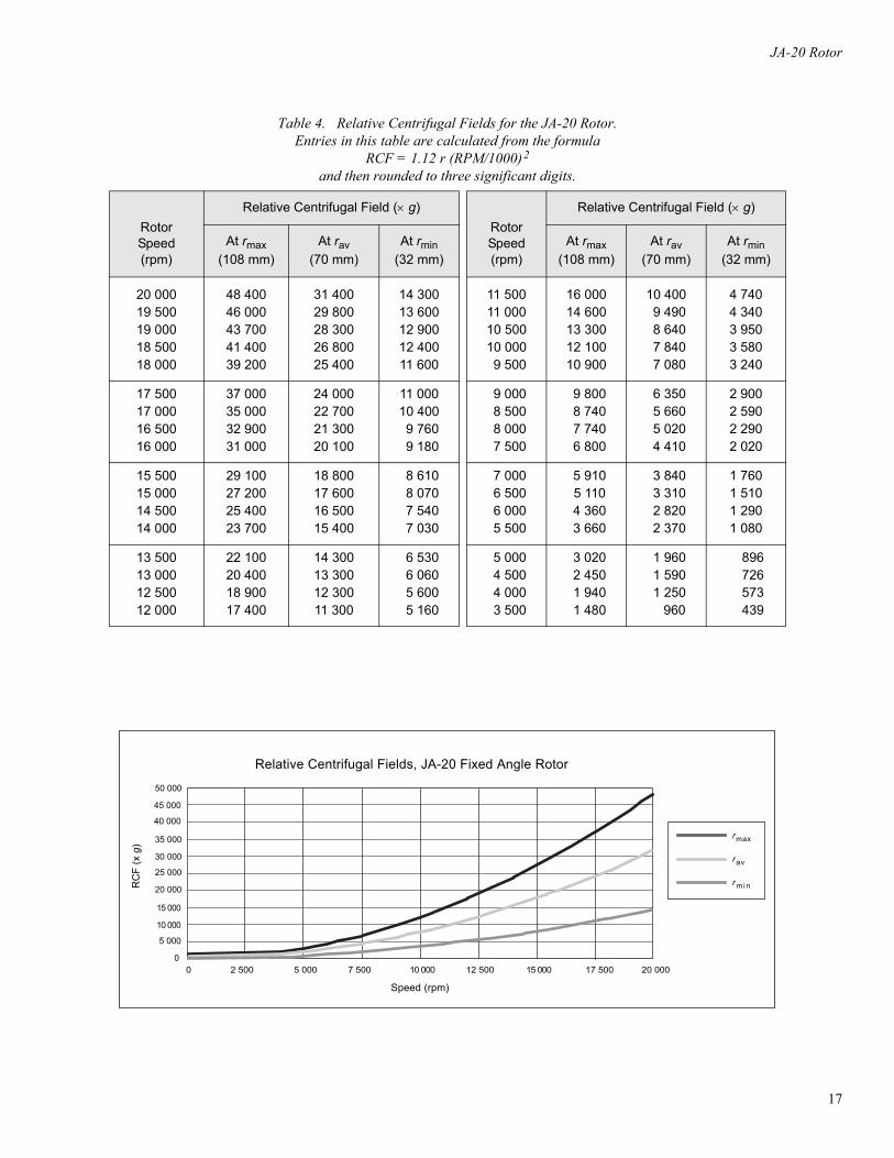
Table 4. Relative Centrifugal Fields for the JA-20 Rotor.Entries in this table are calculated from the formula
RCF = 1.12 r (RPM/1000)2
and then rounded to three significant digits.
RotorSpeed(rpm)
Relative Centrifugal Field (u g)RotorSpeed(rpm)
Relative Centrifugal Field (u g)
At rmax(108 mm)
At rav(70 mm)
At rmin(32 mm)
At rmax(108 mm)
At rav(70 mm)
At rmin(32 mm)
20 00019 50019 00018 50018 000
48 40046 00043 70041 40039 200
31 40029 80028 30026 80025 400
14 30013 60012 90012 40011 600
11 50011 00010 50010 0009 500
16 00014 60013 30012 10010 900
10 4009 4908 6407 8407 080
4 7404 3403 9503 5803 240
17 50017 00016 50016 000
37 00035 00032 90031 000
24 00022 70021 30020 100
11 00010 4009 7609 180
9 0008 5008 0007 500
9 8008 7407 7406 800
6 3505 6605 0204 410
2 9002 5902 2902 020
15 50015 00014 50014 000
29 10027 20025 40023 700
18 80017 60016 50015 400
8 6108 0707 5407 030
7 0006 5006 0005 500
5 9105 1104 3603 660
3 8403 3102 8202 370
1 7601 5101 2901 080
13 50013 00012 50012 000
22 10020 40018 90017 400
14 30013 30012 30011 300
6 5306 0605 6005 160
5 0004 5004 0003 500
3 0202 4501 9401 480
1 9601 5901 250 960
896 726 573 439
Relative Centrifugal Fields, JA-20 Fixed Angle Rotor
Speed (rpm)
RC
F (x
g)
0
5 000
10 000
15 000
20 000
25 000
30 000
35 000
40 000
45 000
50 000
0 5 000 10 000 15 000 20 0002 500 7 500 12 500 17 500
rmax
rav
rmin

Appendix L
Test Rig Microbiological Results
The raw data from the preliminary microbiological testing is included in the following pages.
239
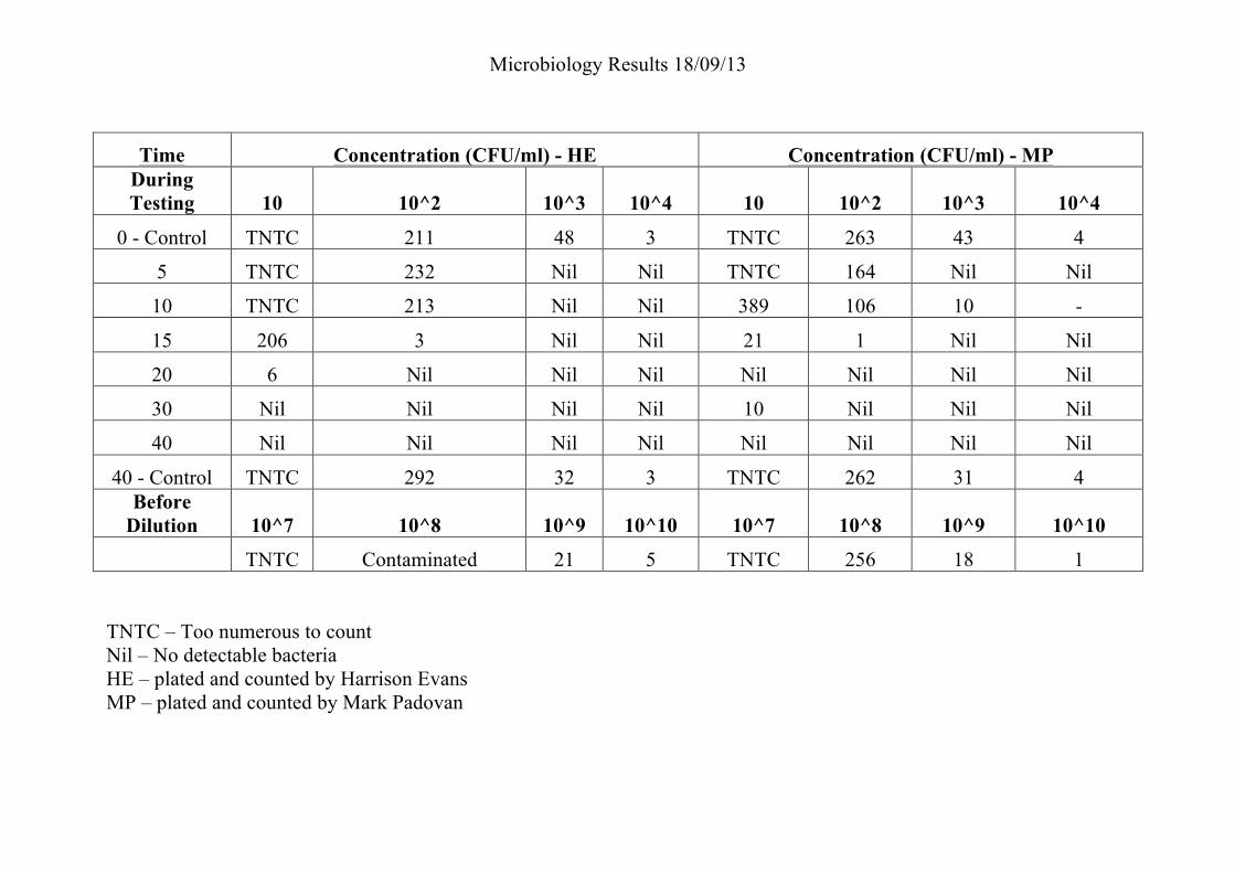
Microbiology Results 18/09/13 !
Time Concentration (CFU/ml) - HE Concentration (CFU/ml) - MP During Testing 10 10^2 10^3 10^4 10 10^2 10^3 10^4
0 - Control TNTC 211 48 3 TNTC 263 43 4
5 TNTC 232 Nil Nil TNTC 164 Nil Nil
10 TNTC 213 Nil Nil 389 106 10 -
15 206 3 Nil Nil 21 1 Nil Nil
20 6 Nil Nil Nil Nil Nil Nil Nil
30 Nil Nil Nil Nil 10 Nil Nil Nil
40 Nil Nil Nil Nil Nil Nil Nil Nil
40 - Control TNTC 292 32 3 TNTC 262 31 4 Before
Dilution 10^7 10^8 10^9 10^10 10^7 10^8 10^9 10^10
TNTC Contaminated 21 5 TNTC 256 18 1
TNTC – Too numerous to count Nil – No detectable bacteria HE – plated and counted by Harrison Evans MP – plated and counted by Mark Padovan

Microbiology Results 04/10/13
Time Concentration (CFU/ml) - HE Concentration (CFU/ml) - MP During Testing 10 10^2 10^3 10^4 10^5 10 10^2 10^3 10^4 10^5
0 - Control TNTC TNTC TNTC 283 Nil TNTC TNTC TNTC 276 Nil 4 TNTC TNTC TNTC 543 65 TNTC TNTC TNTC 612 76 8 TNTC TNTC TNTC 137 Nil TNTC TNTC TNTC 161 Nil
12 TNTC TNTC TNTC 182 22 TNTC TNTC TNTC 133 26 16 TNTC TNTC 225 Nil Nil TNTC TNTC 122 Nil Nil 20 43 Nil Nil Nil Nil 11 Nil Nil Nil Nil 24 Nil Nil Nil Nil Nil Nil Nil Nil Nil Nil 28 Nil Nil Nil Nil Nil Nil Nil Nil Nil Nil 32 Nil Nil Nil Nil Nil Nil Nil Nil Nil Nil 36 Nil Nil Nil Nil Nil Nil Nil Nil Nil Nil 40 Nil Nil Nil Nil Nil Nil Nil Nil Nil Nil
40 - Control Nil Nil Nil Nil Nil Nil Nil Nil Nil Nil SODIS 20 TNTC TNTC TNTC 49 Nil TNTC TNTC TNTC 60 Nil
Before Dilution 10^7 10^8 10^9 10^10 10^7 10^8 10^9 10^10
TNTC 189 12 0 TNTC 180 21 0 TNTC – Too numerous to count Nil – No detectable bacteria HE – plated and counted by Harrison Evans MP – plated and counted by Mark Padovan
Appendix M
Prototype Module Fabrication Breakdown
A prototype module is broken down into its main components. Material selection and construction are
detailed in the following pages.
242
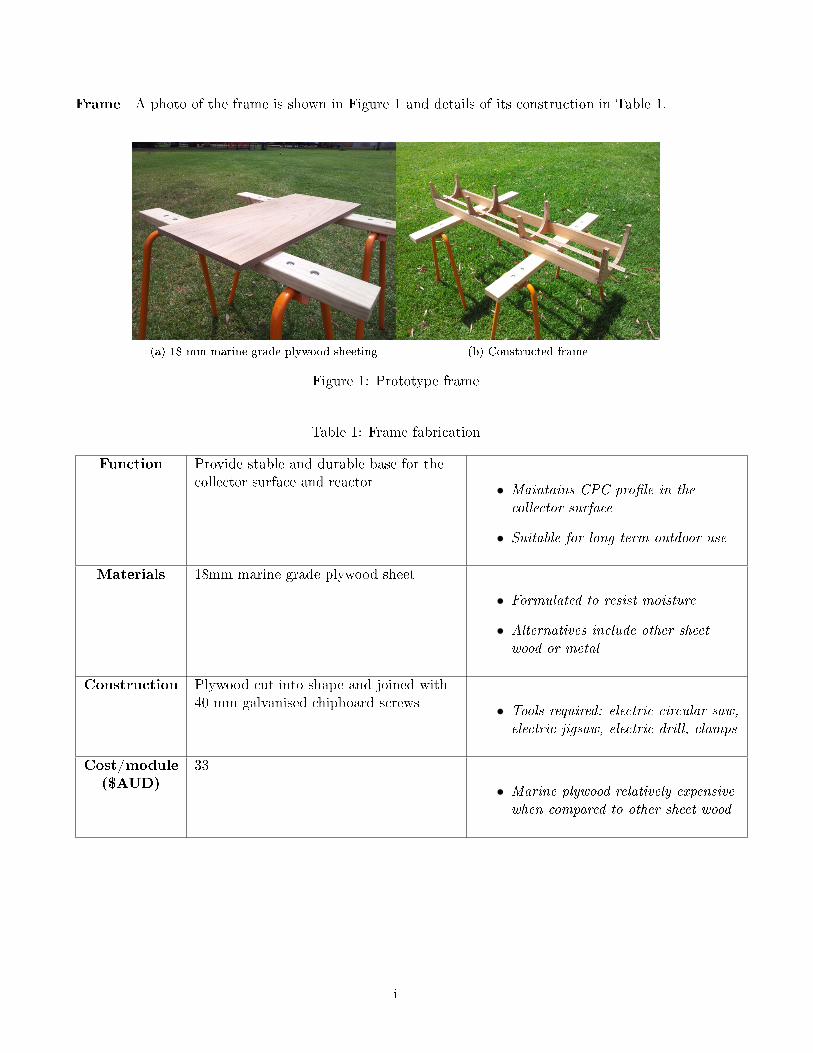
Frame A photo of the frame is shown in Figure 1 and details of its construction in Table 1.
(a) 18 mm marine grade plywood sheeting (b) Constructed frame
Figure 1: Prototype frame
Table 1: Frame fabrication
Function Provide stable and durable base for the
collector surface and reactor • Maintains CPC pro�le in thecollector surface
• Suitable for long term outdoor use
Materials 18mm marine grade plywood sheet
• Formulated to resist moisture
• Alternatives include other sheetwood or metal
Construction Plywood cut into shape and joined with
40 mm galvanised chipboard screws • Tools required: electric circular saw,electric jigsaw, electric drill, clamps
Cost/module($AUD)
33
• Marine plywood relatively expensivewhen compared to other sheet wood
i
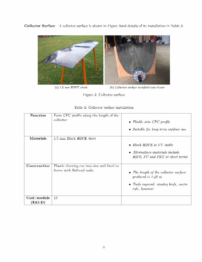
Collector Surface A collector surface is shown in Figure 2and details of its installation in Table 2.
(a) 1.5 mm HDPE sheet (b) Collector surface installed onto frame
Figure 2: Collector surface
Table 2: Collector surface installation
Function Form CPC pro�le along the length of the
collector • Pliable into CPC pro�le
• Suitable for long term outdoor use
Materials 1.5 mm Black HDPE sheet
• Black HDPE is UV stable
• Alternatives materials includeHIPS, PC and PET or sheet metal
Construction Plastic sheeting cut into size and �xed to
frame with �athead nails. • The length of the collector surfaceproduced is 1.46 m
• Tools required: stanley knife, metrerule, hammer
Cost/module($AUD)
13
ii
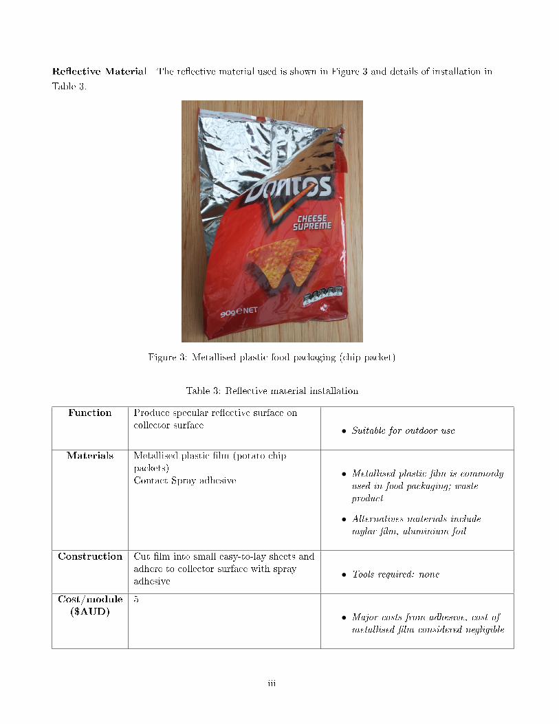
Re�ective Material The re�ective material used is shown in Figure 3 and details of installation in
Table 3.
Figure 3: Metallised plastic food packaging (chip packet)
Table 3: Re�ective material installation
Function Produce specular re�ective surface on
collector surface • Suitable for outdoor use
Materials Metallised plastic �lm (potato chip
packets)
Contact Spray adhesive• Metallised plastic �lm is commonlyused in food packaging; wasteproduct
• Alternatives materials includemylar �lm, aluminium foil
Construction Cut �lm into small easy-to-lay sheets and
adhere to collector surface with spray
adhesive• Tools required: none
Cost/module($AUD)
5
• Major costs from adhesive, cost ofmetallised �lm considered negligible
iii
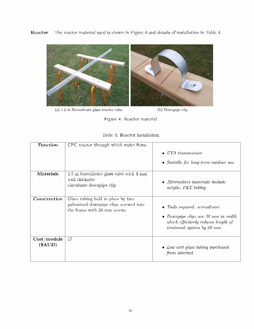
Reactor The reactor material used is shown in Figure 4 and details of installation in Table 4.
(a) 1.5 m Borosilicate glass reactor tube (b) Downpipe clip
Figure 4: Reactor material
Table 4: Reactor installation
Function CPC reactor through which water �ows
• UVA transmissive
• Suitable for long term outdoor use
Materials 1.5 m borosilicate glass tube with 4 mm
wall thickness
zincalume downpipe clip• Alternatives materials includeacrylic, PET tubing
Construction Glass tubing held in place by two
galvanised downpipe clips screwed into
the frame with 20 mm screws• Tools required: screwdriver
• Downpipe clips are 30 mm in widthwhich e�ectively reduces length oftreatment system by 60 mm
Cost/module($AUD)
17
• Low cost glass tubing purchasedfrom internet
iv
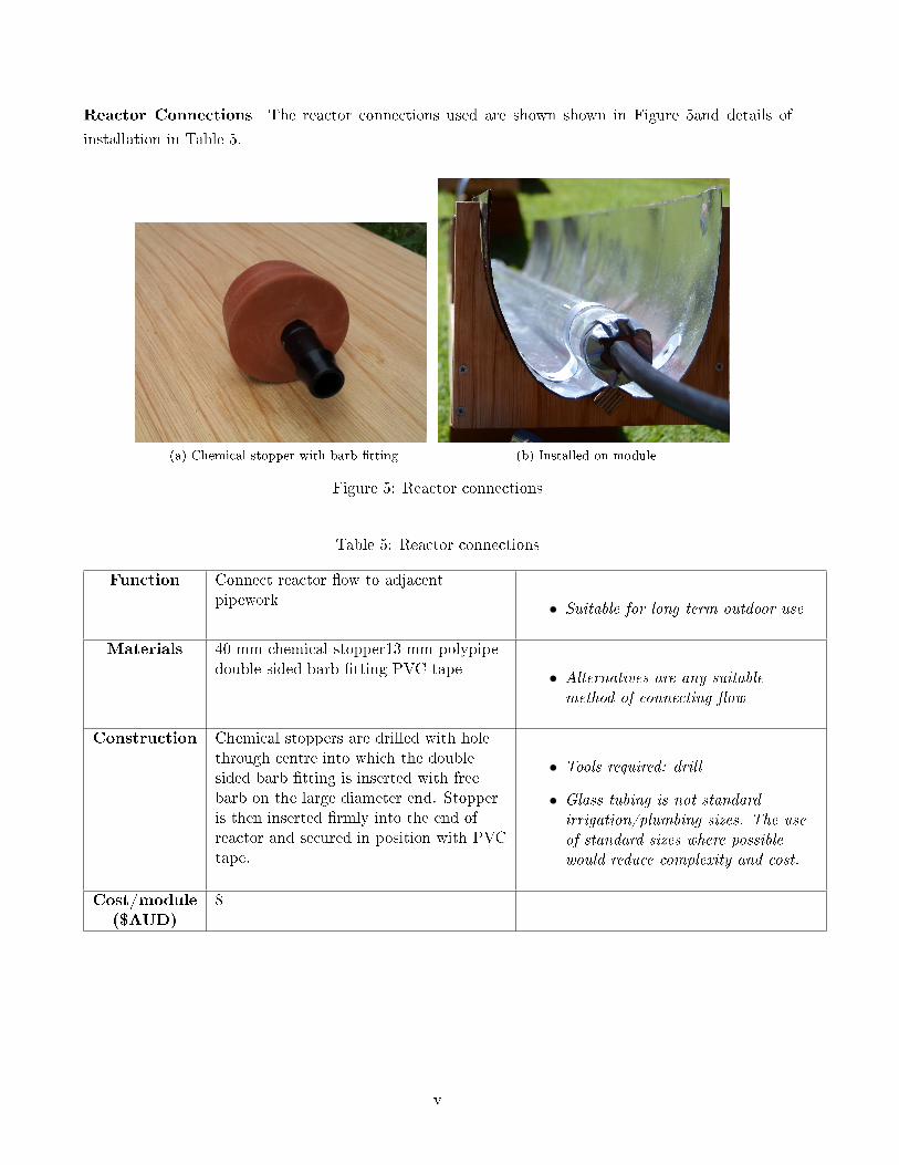
Reactor Connections The reactor connections used are shown shown in Figure 5and details of
installation in Table 5.
(a) Chemical stopper with barb �tting (b) Installed on module
Figure 5: Reactor connections
Table 5: Reactor connections
Function Connect reactor �ow to adjacent
pipework • Suitable for long term outdoor use
Materials 40 mm chemical stopper13 mm polypipe
double sided barb �tting PVC tape • Alternatives are any suitablemethod of connecting �ow
Construction Chemical stoppers are drilled with hole
through centre into which the double
sided barb �tting is inserted with free
barb on the large diameter end. Stopper
is then inserted �rmly into the end of
reactor and secured in position with PVC
tape.
• Tools required: drill
• Glass tubing is not standardirrigation/plumbing sizes. The useof standard sizes where possiblewould reduce complexity and cost.
Cost/module($AUD)
8
v
Appendix N
Bill of Purchased Materials for Prototype
A bill of all materials used in the fabrication of the prototype system is shown in the following pages.
248
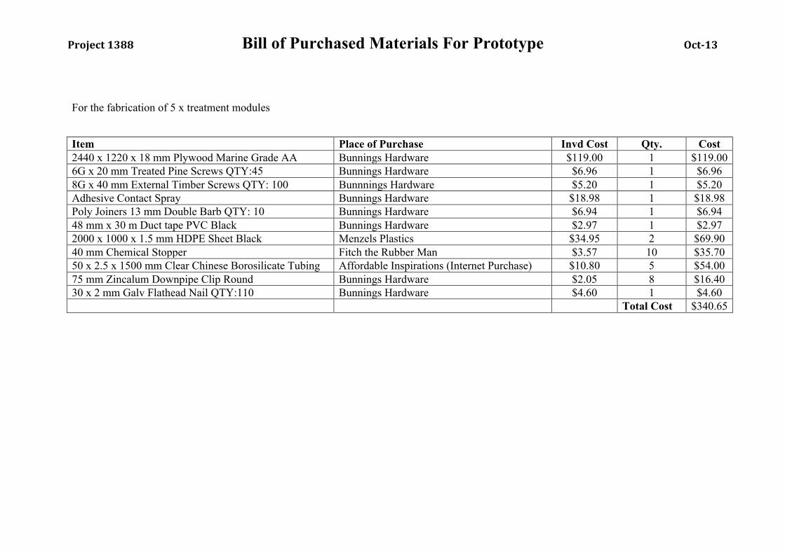
Project 1388 Bill of Purchased Materials For Prototype Oct-‐13
For the fabrication of 5 x treatment modules
Item Place of Purchase Invd Cost Qty. Cost 2440 x 1220 x 18 mm Plywood Marine Grade AA Bunnings Hardware $119.00 1 $119.00 6G x 20 mm Treated Pine Screws QTY:45 Bunnings Hardware $6.96 1 $6.96 8G x 40 mm External Timber Screws QTY: 100 Bunnnings Hardware $5.20 1 $5.20 Adhesive Contact Spray Bunnings Hardware $18.98 1 $18.98 Poly Joiners 13 mm Double Barb QTY: 10 Bunnings Hardware $6.94 1 $6.94 48 mm x 30 m Duct tape PVC Black Bunnings Hardware $2.97 1 $2.97 2000 x 1000 x 1.5 mm HDPE Sheet Black Menzels Plastics $34.95 2 $69.90 40 mm Chemical Stopper Fitch the Rubber Man $3.57 10 $35.70 50 x 2.5 x 1500 mm Clear Chinese Borosilicate Tubing Affordable Inspirations (Internet Purchase) $10.80 5 $54.00 75 mm Zincalum Downpipe Clip Round Bunnings Hardware $2.05 8 $16.40 30 x 2 mm Galv Flathead Nail QTY:110 Bunnings Hardware $4.60 1 $4.60 Total Cost $340.65

Appendix O
Prototype Microbiological results
The raw microbiological results for the full scale prototype test are given here.
250
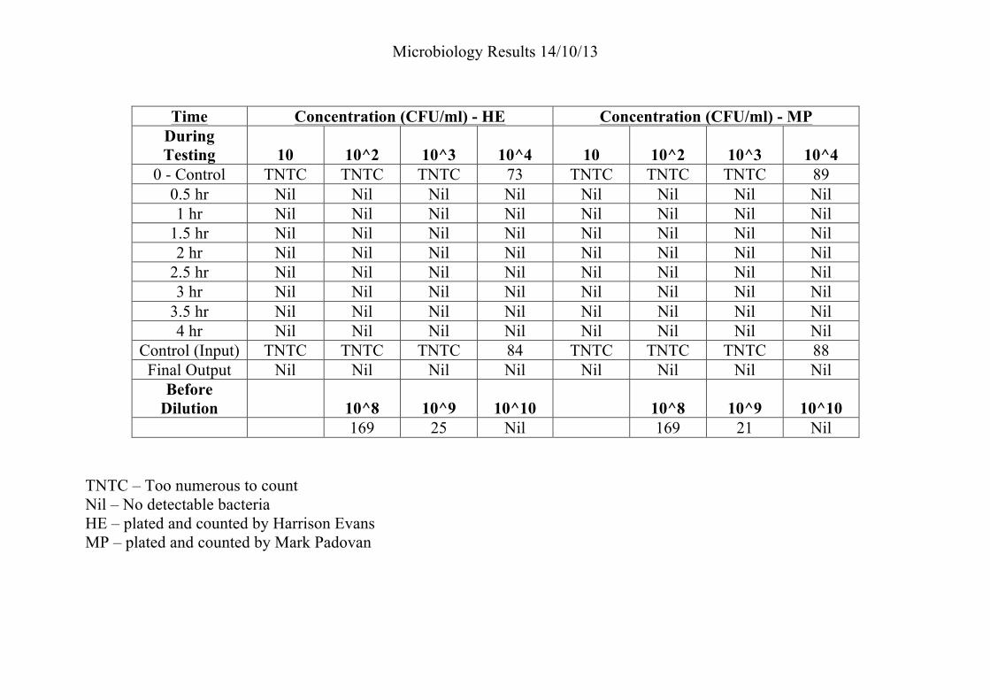
Microbiology Results 14/10/13!
! !
Time Concentration (CFU/ml) - HE Concentration (CFU/ml) - MP During Testing 10 10^2 10^3 10^4 10 10^2 10^3 10^4
0 - Control TNTC TNTC TNTC 73 TNTC TNTC TNTC 89 0.5 hr Nil Nil Nil Nil Nil Nil Nil Nil 1 hr Nil Nil Nil Nil Nil Nil Nil Nil
1.5 hr Nil Nil Nil Nil Nil Nil Nil Nil 2 hr Nil Nil Nil Nil Nil Nil Nil Nil
2.5 hr Nil Nil Nil Nil Nil Nil Nil Nil 3 hr Nil Nil Nil Nil Nil Nil Nil Nil
3.5 hr Nil Nil Nil Nil Nil Nil Nil Nil 4 hr Nil Nil Nil Nil Nil Nil Nil Nil
Control (Input) TNTC TNTC TNTC 84 TNTC TNTC TNTC 88 Final Output Nil Nil Nil Nil Nil Nil Nil Nil
Before Dilution 10^8 10^9 10^10 10^8 10^9 10^10
169 25 Nil 169 21 Nil TNTC – Too numerous to count Nil – No detectable bacteria HE – plated and counted by Harrison Evans MP – plated and counted by Mark Padovan
Appendix P
Operation Guide
An example of an operation guide that could be used for implementation is shown in the following
pages.
252

SODIS uses sunlight to kill
germs in the water!
SAFE AND TASTY
DRINKING WATER!
Two million people use SODIS
treatment every day!
Recommended by the World
Health Organisation!
“I am very happy that my children are now
drinking clean water”
“I now have time to look after my children
and earn money for their education”
Easy access to safe
drinking water
How to use your new SODIS
water treatment system
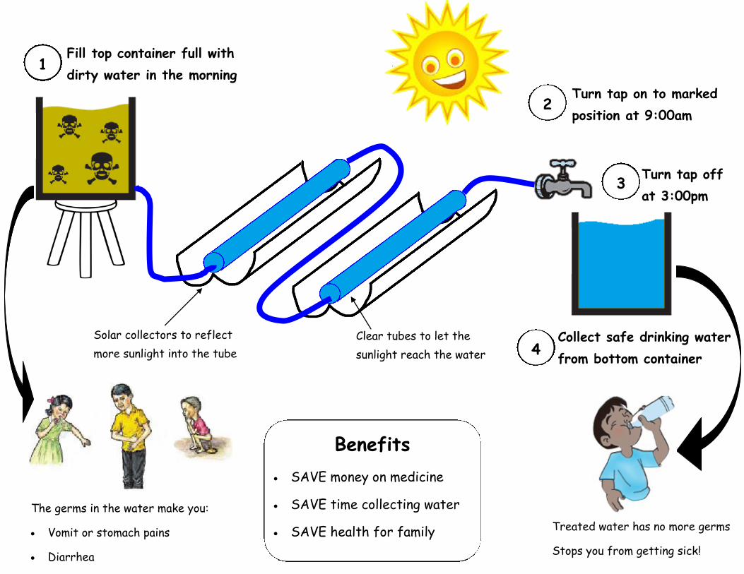
Fill top container full with
dirty water in the morning 1
Collect safe drinking water
from bottom container 4
Turn tap on to marked
position at 9:00am
Turn tap off
at 3:00pm
2
3
Solar collectors to reflect
more sunlight into the tube
Clear tubes to let the
sunlight reach the water
The germs in the water make you:
Vomit or stomach pains
Diarrhea
Treated water has no more germs
Stops you from getting sick!
Benefits
SAVE money on medicine
SAVE time collecting water
SAVE health for family
Appendix Q
Capital Expenditure List
A detailed expenditure list, including all project expenses is detailed in the following pages.
255
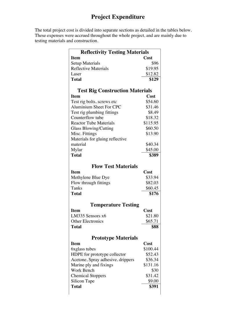
Project Expenditure
The total project cost is divided into separate sections as detailed in the tables below. These expenses were accrued throughout the whole project, and are mainly due to testing materials and construction.
Reflectivity Testing Materials Item Cost Setup Materials $96 Reflective Materials $19.95 Laser $12.82 Total $129
Test Rig Construction Materials Item Cost Test rig bolts, screws etc $54.60 Aluminium Sheet For CPC $31.46 Test rig plumbing fittings $8.49 Counterflow tube $18.32 Reactor Tube Materials $115.95 Glass Blowing/Cutting $60.50 Misc. Fittings $13.90 Materials for gluing reflective material $40.34 Mylar $45.00 Total $389
Flow Test Materials Item Cost Methylene Blue Dye $33.94 Flow through fittings $82.03 Tanks $60.45 Total $176
Temperature Testing Item Cost LM335 Sensors x6 $21.80 Other Electronics $65.71 Total $88
Prototype Materials Item Cost 6xglass tubes $100.44 HDPE for prototype collector $52.43 Acetone, Spray adhesive, drippers $36.34 Marine ply and fixings $131.16 Work Bench $30 Chemical Stoppers $31.42 Silicon Tape $9.00 Total $391
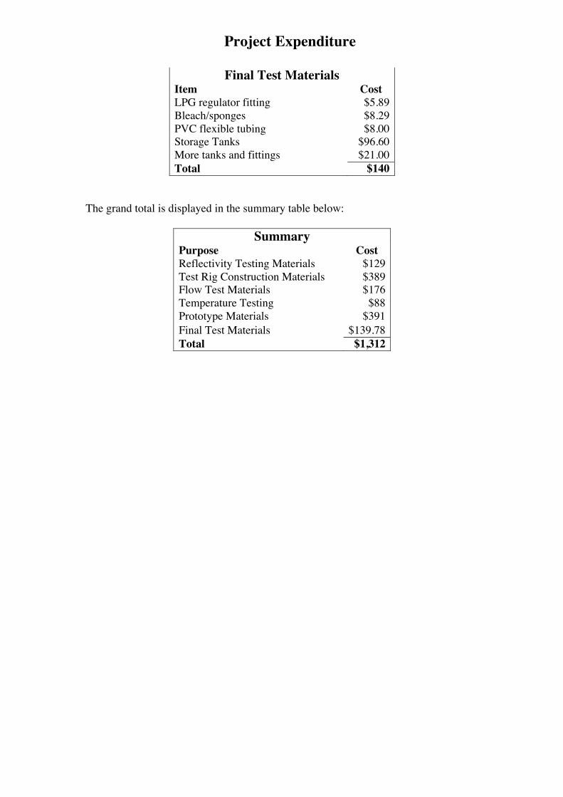
Project Expenditure
Final Test Materials Item Cost LPG regulator fitting $5.89 Bleach/sponges $8.29 PVC flexible tubing $8.00 Storage Tanks $96.60 More tanks and fittings $21.00 Total $140
The grand total is displayed in the summary table below:
Summary Purpose Cost Reflectivity Testing Materials $129 Test Rig Construction Materials $389 Flow Test Materials $176 Temperature Testing $88 Prototype Materials $391 Final Test Materials $139.78 Total $1,312
Appendix R
Work Breakdown Structure
A level three WBS for the project is detailed in the following diagram.
258
�
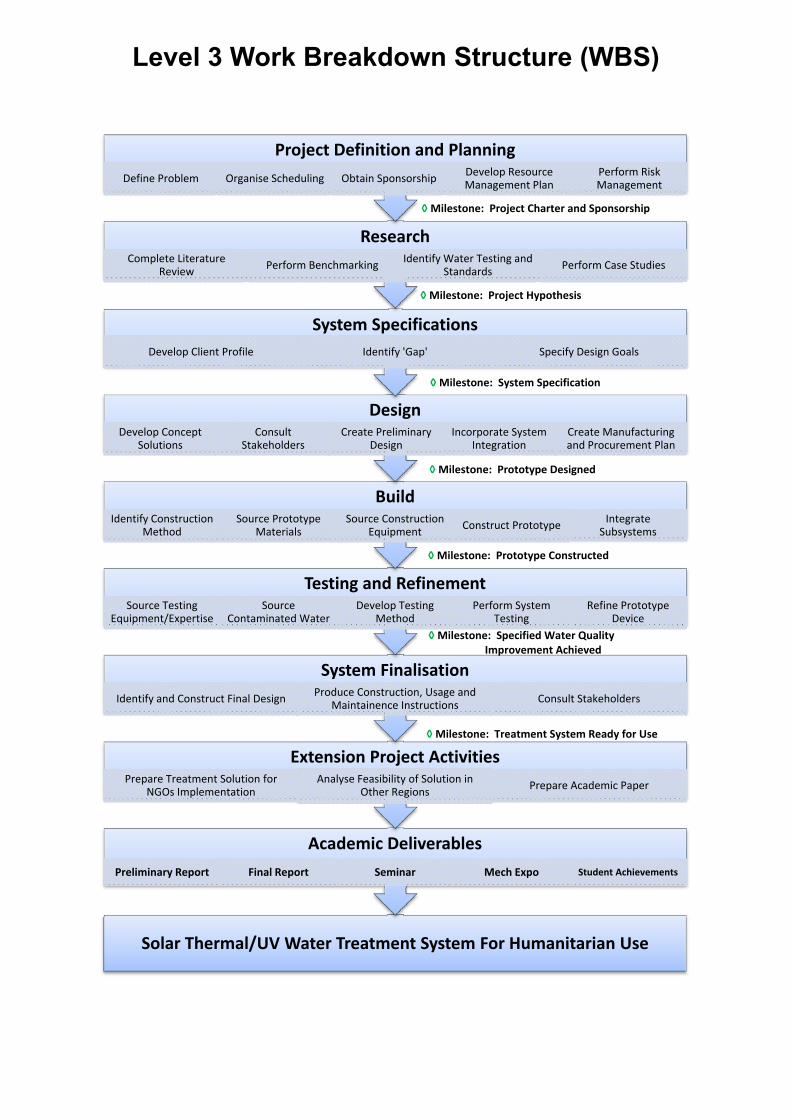
Level 3 Work Breakdown Structure (WBS)
����
Solar�Thermal/UV�Water�Treatment�System�For�Humanitarian�Use
Academic�Deliverables�Preliminary�Report Final�Report Seminar Mech�Expo Student�Achievements
Extension�Project�ActivitiesPrepare�Treatment�Solution�for�
NGOs�ImplementationAnalyse�Feasibility�of�Solution�in�
Other�Regions Prepare�Academic�Paper
System�FinalisationIdentify�and�Construct�Final�Design Produce�Construction,�Usage�and�
Maintainence�Instructions Consult�Stakeholders��
Testing�and�RefinementSource�Testing�
Equipment/ExpertiseSource�
Contaminated�WaterDevelop�Testing�
Method�Perform�System�
TestingRefine�Prototype�
Device
BuildIdentify�Construction�
MethodSource�Prototype�
MaterialsSource�Construction�
Equipment Construct�Prototype Integrate�Subsystems
DesignDevelop�Concept�
SolutionsConsult�
StakeholdersCreate�Preliminary�
DesignIncorporate�System�
IntegrationCreate�Manufacturing�and�Procurement�Plan
System�SpecificationsDevelop�Client�Profile Identify�'Gap' Specify�Design�Goals
ResearchComplete�Literature�
Review Perform�Benchmarking Identify�Water�Testing�and�Standards� Perform�Case�Studies
Project�Definition�and�PlanningDefine�Problem Organise�Scheduling Obtain�Sponsorship Develop�Resource�
Management�PlanPerform�Risk�Management
ѕMilestone:��Project�Charter�and�Sponsorship�
ѕMilestone:��Prototype�Constructed�
ѕ�Milestone:��Treatment�System�Ready�for�Use��
ѕ�Milestone:��Specified�Water�Quality�Improvement�Achieved�
ѕMilestone:��Prototype�Designed����
ѕMilestone:��Project�Hypothesis��
ѕMilestone: �System�Specification�
Appendix S
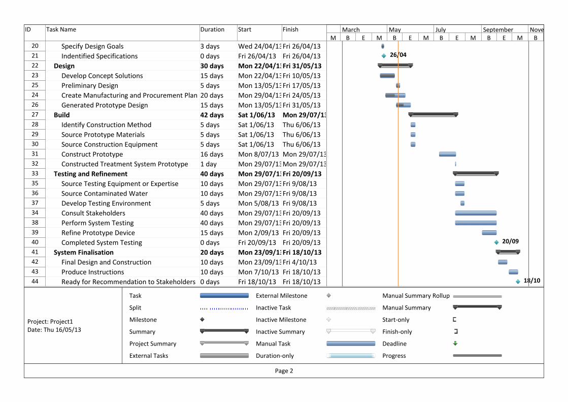
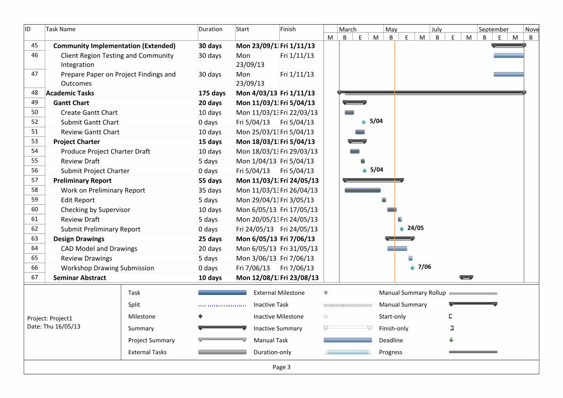
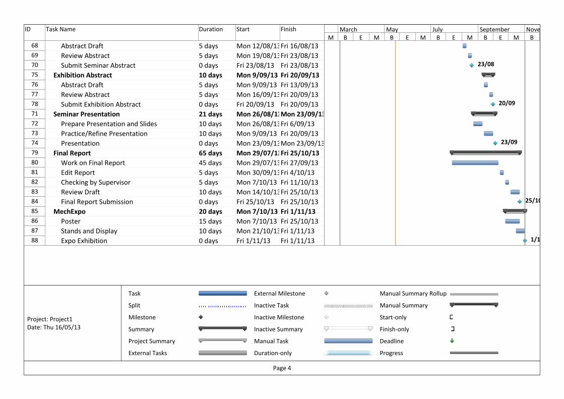
Gantt Chart
A Gantt chart outlining the full project schedule is shown can be found in the following pages.
260
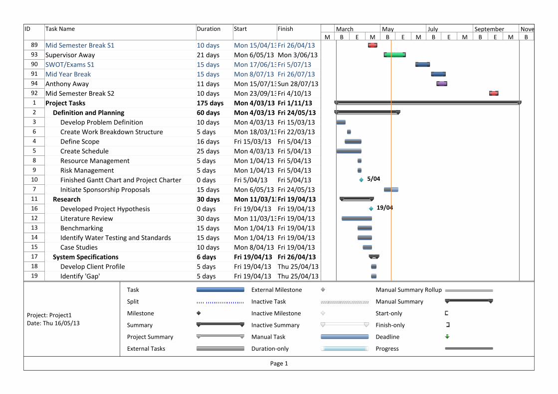
ID Task Name Duration Start Finish
89 Mid Semester Break S1 10 days Mon 15/04/13Fri 26/04/13
93 Supervisor Away 21 days Mon 6/05/13 Mon 3/06/13
90 SWOT/Exams S1 15 days Mon 17/06/13Fri 5/07/13
91 Mid Year Break 15 days Mon 8/07/13 Fri 26/07/13
94 Anthony Away 11 days Mon 15/07/13Sun 28/07/13
92 Mid Semester Break S2 10 days Mon 23/09/13Fri 4/10/13
1 Project Tasks 175 days Mon 4/03/13 Fri 1/11/13
2 Definition and Planning 60 days Mon 4/03/13 Fri 24/05/13
3 Develop Problem Definition 10 days Mon 4/03/13 Fri 15/03/13
6 Create Work Breakdown Structure 5 days Mon 18/03/13Fri 22/03/13
4 Define Scope 16 days Fri 15/03/13 Fri 5/04/13
5 Create Schedule 25 days Mon 4/03/13 Fri 5/04/13
8 Resource Management 5 days Mon 1/04/13 Fri 5/04/13
9 Risk Management 5 days Mon 1/04/13 Fri 5/04/13
10 Finished Gantt Chart and Project Charter 0 days Fri 5/04/13 Fri 5/04/13
7 Initiate Sponsorship Proposals 15 days Mon 6/05/13 Fri 24/05/13
11 Research 30 days Mon 11/03/13Fri 19/04/13
16 Developed Project Hypothesis 0 days Fri 19/04/13 Fri 19/04/13
12 Literature Review 30 days Mon 11/03/13Fri 19/04/13
13 Benchmarking 15 days Mon 1/04/13 Fri 19/04/13
14 Identify Water Testing and Standards 15 days Mon 1/04/13 Fri 19/04/13
15 Case Studies 10 days Mon 8/04/13 Fri 19/04/13
17 System Specifications 6 days Fri 19/04/13 Fri 26/04/13
18 Develop Client Profile 5 days Fri 19/04/13 Thu 25/04/13
19 Identify 'Gap' 5 days Fri 19/04/13 Thu 25/04/13
5/04
19/04
M B E M B E M B E M B E M B
March May July September November
Task
Split
Milestone
Summary
Project Summary
External Tasks
External Milestone
Inactive Task
Inactive Milestone
Inactive Summary
Manual Task
Duration-only
Manual Summary Rollup
Manual Summary
Start-only
Finish-only
Deadline
Progress
Page 1
Project: Project1
Date: Thu 16/05/13
ID Task Name Duration Start Finish
20 Specify Design Goals 3 days Wed 24/04/13Fri 26/04/13
21 Indentified Specifications 0 days Fri 26/04/13 Fri 26/04/13
22 Design 30 days Mon 22/04/13Fri 31/05/13
23 Develop Concept Solutions 15 days Mon 22/04/13Fri 10/05/13
25 Preliminary Design 5 days Mon 13/05/13Fri 17/05/13
24 Create Manufacturing and Procurement Plan 20 days Mon 29/04/13Fri 24/05/13
26 Generated Prototype Design 15 days Mon 13/05/13Fri 31/05/13
27 Build 42 days Sat 1/06/13 Mon 29/07/13
28 Identify Construction Method 5 days Sat 1/06/13 Thu 6/06/13
29 Source Prototype Materials 5 days Sat 1/06/13 Thu 6/06/13
30 Source Construction Equipment 5 days Sat 1/06/13 Thu 6/06/13
31 Construct Prototype 16 days Mon 8/07/13 Mon 29/07/13
32 Constructed Treatment System Prototype 1 day Mon 29/07/13Mon 29/07/13
33 Testing and Refinement 40 days Mon 29/07/13Fri 20/09/13
35 Source Testing Equipment or Expertise 10 days Mon 29/07/13Fri 9/08/13
36 Source Contaminated Water 10 days Mon 29/07/13Fri 9/08/13
37 Develop Testing Environment 5 days Mon 5/08/13 Fri 9/08/13
34 Consult Stakeholders 40 days Mon 29/07/13Fri 20/09/13
38 Perform System Testing 40 days Mon 29/07/13Fri 20/09/13
39 Refine Prototype Device 15 days Mon 2/09/13 Fri 20/09/13
40 Completed System Testing 0 days Fri 20/09/13 Fri 20/09/13
41 System Finalisation 20 days Mon 23/09/13Fri 18/10/13
42 Final Design and Construction 10 days Mon 23/09/13Fri 4/10/13
43 Produce Instructions 10 days Mon 7/10/13 Fri 18/10/13
44 Ready for Recommendation to Stakeholders 0 days Fri 18/10/13 Fri 18/10/13
26/04
20/09
18/10
M B E M B E M B E M B E M B
March May July September November
Task
Split
Milestone
Summary
Project Summary
External Tasks
External Milestone
Inactive Task
Inactive Milestone
Inactive Summary
Manual Task
Duration-only
Manual Summary Rollup
Manual Summary
Start-only
Finish-only
Deadline
Progress
Page 2
Project: Project1
Date: Thu 16/05/13
ID Task Name Duration Start Finish
45 Community Implementation (Extended) 30 days Mon 23/09/13Fri 1/11/13
46 Client Region Testing and Community
Integration
30 days Mon
23/09/13
Fri 1/11/13
47 Prepare Paper on Project Findings and
Outcomes
30 days Mon
23/09/13
Fri 1/11/13
48 Academic Tasks 175 days Mon 4/03/13 Fri 1/11/13
49 Gantt Chart 20 days Mon 11/03/13Fri 5/04/13
50 Create Gantt Chart 10 days Mon 11/03/13Fri 22/03/13
52 Submit Gantt Chart 0 days Fri 5/04/13 Fri 5/04/13
51 Review Gantt Chart 10 days Mon 25/03/13Fri 5/04/13
53 Project Charter 15 days Mon 18/03/13Fri 5/04/13
54 Produce Project Charter Draft 10 days Mon 18/03/13Fri 29/03/13
55 Review Draft 5 days Mon 1/04/13 Fri 5/04/13
56 Submit Project Charter 0 days Fri 5/04/13 Fri 5/04/13
57 Preliminary Report 55 days Mon 11/03/13Fri 24/05/13
58 Work on Preliminary Report 35 days Mon 11/03/13Fri 26/04/13
59 Edit Report 5 days Mon 29/04/13Fri 3/05/13
60 Checking by Supervisor 10 days Mon 6/05/13 Fri 17/05/13
61 Review Draft 5 days Mon 20/05/13Fri 24/05/13
62 Submit Preliminary Report 0 days Fri 24/05/13 Fri 24/05/13
63 Design Drawings 25 days Mon 6/05/13 Fri 7/06/13
64 CAD Model and Drawings 20 days Mon 6/05/13 Fri 31/05/13
65 Review Drawings 5 days Mon 3/06/13 Fri 7/06/13
66 Workshop Drawing Submission 0 days Fri 7/06/13 Fri 7/06/13
67 Seminar Abstract 10 days Mon 12/08/13Fri 23/08/13
5/04
5/04
24/05
7/06
M B E M B E M B E M B E M B
March May July September November
Task
Split
Milestone
Summary
Project Summary
External Tasks
External Milestone
Inactive Task
Inactive Milestone
Inactive Summary
Manual Task
Duration-only
Manual Summary Rollup
Manual Summary
Start-only
Finish-only
Deadline
Progress
Page 3
Project: Project1
Date: Thu 16/05/13
ID Task Name Duration Start Finish
68 Abstract Draft 5 days Mon 12/08/13Fri 16/08/13
69 Review Abstract 5 days Mon 19/08/13Fri 23/08/13
70 Submit Seminar Abstract 0 days Fri 23/08/13 Fri 23/08/13
75 Exhibition Abstract 10 days Mon 9/09/13 Fri 20/09/13
76 Abstract Draft 5 days Mon 9/09/13 Fri 13/09/13
77 Review Abstract 5 days Mon 16/09/13Fri 20/09/13
78 Submit Exhibition Abstract 0 days Fri 20/09/13 Fri 20/09/13
71 Seminar Presentation 21 days Mon 26/08/13Mon 23/09/13
72 Prepare Presentation and Slides 10 days Mon 26/08/13Fri 6/09/13
73 Practice/Refine Presentation 10 days Mon 9/09/13 Fri 20/09/13
74 Presentation 0 days Mon 23/09/13Mon 23/09/13
79 Final Report 65 days Mon 29/07/13Fri 25/10/13
80 Work on Final Report 45 days Mon 29/07/13Fri 27/09/13
81 Edit Report 5 days Mon 30/09/13Fri 4/10/13
82 Checking by Supervisor 5 days Mon 7/10/13 Fri 11/10/13
83 Review Draft 10 days Mon 14/10/13Fri 25/10/13
84 Final Report Submission 0 days Fri 25/10/13 Fri 25/10/13
85 MechExpo 20 days Mon 7/10/13 Fri 1/11/13
86 Poster 15 days Mon 7/10/13 Fri 25/10/13
87 Stands and Display 10 days Mon 21/10/13Fri 1/11/13
88 Expo Exhibition 0 days Fri 1/11/13 Fri 1/11/13
23/08
20/09
23/09
25/10
1/11
M B E M B E M B E M B E M B
March May July September November
Task
Split
Milestone
Summary
Project Summary
External Tasks
External Milestone
Inactive Task
Inactive Milestone
Inactive Summary
Manual Task
Duration-only
Manual Summary Rollup
Manual Summary
Start-only
Finish-only
Deadline
Progress
Page 4
Project: Project1
Date: Thu 16/05/13