
APPENDIX DA2/01/APP1 ARCHITECTURAL STUDY · Responses to Examining Authority's Second Written...
39
Responses to Examining Authority's Second Written Questions North Killingholme Power Project Traffic and Transport C.GEN Killingholme Limited APPENDIX DA2/01/APP1 ARCHITECTURAL STUDY
Transcript of APPENDIX DA2/01/APP1 ARCHITECTURAL STUDY · Responses to Examining Authority's Second Written...

Responses to Examining Authority's Second Written Questions North Killingholme Power ProjectTraffic and Transport C.GEN Killingholme Limited
APPENDIX DA2/01/APP1
ARCHITECTURAL STUDY
NORTH KILLINGHOLME POWER PROJECT:ARCHITECTURAL STUDY
JANUARY 2014
1

2
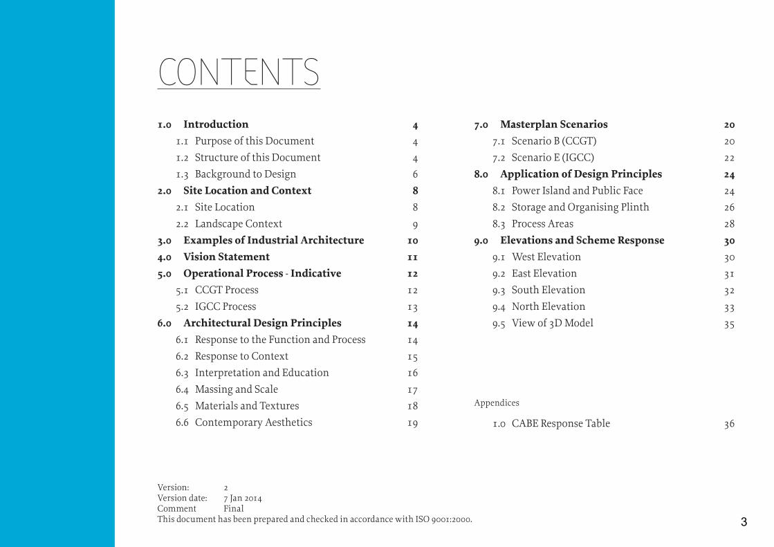
Version: 2Version date: 7 Jan 2014Comment FinalThis document has been prepared and checked in accordance with ISO 9001:2000.
CONTENTS1.0 Introduction 4
1.1 Purpose of this Document 4
1.2 Structure of this Document 4
1.3 Background to Design 6
2.0 Site Location and Context 82.1 Site Location 8
2.2 Landscape Context 9
3.0 Examples of Industrial Architecture 104.0 Vision Statement 115.0 Operational Process - Indicative 12
5.1 CCGT Process 12
5.2 IGCC Process 13
6.0 Architectural Design Principles 146.1 Response to the Function and Process 14
6.2 Response to Context 15
6.3 Interpretation and Education 16
6.4 Massing and Scale 17
6.5 Materials and Textures 18
6.6 Contemporary Aesthetics 19
7.0 Masterplan Scenarios 207.1 Scenario B (CCGT) 20
7.2 Scenario E (IGCC) 22
8.0 Application of Design Principles 248.1 Power Island and Public Face 24
8.2 Storage and Organising Plinth 26
8.3 Process Areas 28
9.0 Elevations and Scheme Response 309.1 West Elevation 30
9.2 East Elevation 31
9.3 South Elevation 32
9.4 North Elevation 33
9.5 View of 3D Model 35
Appendices
1.0 CABE Response Table 36
3

4 NORTH KILLINGHOLME | ARCHITECTURAL STUDY
1.0 INTRODUCTION
This Architectural Study document augments the Design and Access Statement included in the development consent application (“Application”) for the North Killingholme Power Project (“Project”) and bearing document reference 8.3. It has been prepared in response to the Examining Authority’s Second Written Questions, specifically:
� DA2/01 - CABE queries are addressed by the further work on design principles and their application, along with a tabulated response as requested;
� DA2/02 - architectural design is addressed by creating an enhanced set of design principles, diagrams and text showing the application of these principles through drawings and 3D modelling, precedents and materials.;
� DA2/04 - drawing specificity is addressed by new rendered elevations with notes showing the application of principles and updated planning drawings 2/15-2/28, to be provided later; and
� DA2/06 - visitor centre/educational facility is addressed by the design principle and diagrams (Interpretation and Education)
The Architectural Study should be read together with other material submitted with the Application by the applicant. The document can be read as an addendum to the Design and Access Statement (Doc Ref: 8.3).
The purpose of this document is to:
� Provide a clear design rationale, which responds to the context of the site; � Provide more clearly defined project design principles, informed by guidance
from relevant documentation; and � Provide graphical descriptions of the nature of the operational activity of the
project, and how this (and the context of the project) influences the layout of the works.
This document, which has been prepared by independent consultants LDA Design and AEW Architects.
This document has been structured as follows:
� Introduction: Brief description of the documents purpose and contents, alongside publications that are used to inform and measure C.Gen’s design intentions/proposals for the Project;
� Site Location and Context: Series of diagrams showing the geographical location and boundary of the site;
� Examples of Industrial Architecture: Images showing examples of successfully designed industrial architecture;
� Vision Statement: This is an overall mission statement expressing the design intentions for the site. The description includes how the Project’s character and identity will respond to the existing site and its surroundings;
� IGCC Process: A simplified breakdown of the IGCC process, to express its relationship with the design and layout of the Project, assisted by a detailed description to explain how the IGCC process works;
� Architectural Design Principles: A clear set of design principles that will guide the detail design and inform what will be delivered architecturally. This is also assisted by a series of diagrams illustrating the application of principles to the site design.
The six architectural design principles are:
� Response to the Function and Process � Response to Context � Interpretation and Education � Massing and Scale � Materials and Textures � Contemporary Aesthetics
1.1 PURPOSE OF THIS DOCUMENT 1.2 STRUCTURE OF THIS DOCUMENT
4

� Masterplan Scenarios: Illustrative masterplans for the two operational scenarios applicable to the Project.
� Application of Design Principles: Approach to the selection of materials informed through an understanding of operational requirement, site context and design aspirations outlined in the study;
� Elevations and Scheme Response: Site elevations in response to scheme improvements, indicating material types and colours alongside a model of the Project in 3D; and
� Appendix 1.0: Tabular response to CABE queries contained in their letter of 11 June 2013.
5
6 NORTH KILLINGHOLME | ARCHITECTURAL STUDY
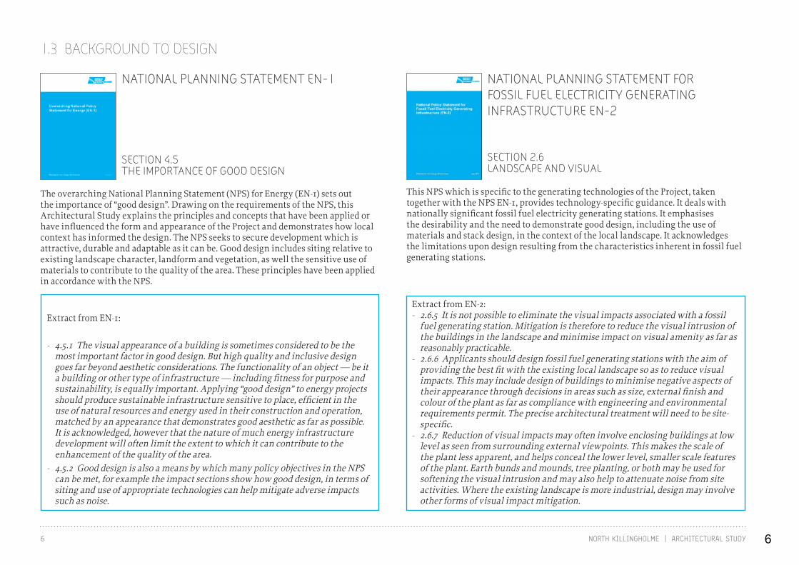
Extract from EN-1:
- 4.5.1 The visual appearance of a building is sometimes considered to be the most important factor in good design. But high quality and inclusive design goes far beyond aesthetic considerations. The functionality of an object — be it a building or other type of infrastructure — including fitness for purpose and sustainability, is equally important. Applying “good design” to energy projects should produce sustainable infrastructure sensitive to place, efficient in the use of natural resources and energy used in their construction and operation, matched by an appearance that demonstrates good aesthetic as far as possible. It is acknowledged, however that the nature of much energy infrastructure development will often limit the extent to which it can contribute to the enhancement of the quality of the area.
- 4.5.2 Good design is also a means by which many policy objectives in the NPS can be met, for example the impact sections show how good design, in terms of siting and use of appropriate technologies can help mitigate adverse impacts such as noise.
Extract from EN-2: - 2.6.5 It is not possible to eliminate the visual impacts associated with a fossil
fuel generating station. Mitigation is therefore to reduce the visual intrusion of the buildings in the landscape and minimise impact on visual amenity as far as reasonably practicable.
- 2.6.6 Applicants should design fossil fuel generating stations with the aim of providing the best fit with the existing local landscape so as to reduce visual impacts. This may include design of buildings to minimise negative aspects of their appearance through decisions in areas such as size, external finish and colour of the plant as far as compliance with engineering and environmental requirements permit. The precise architectural treatment will need to be site-specific.
- 2.6.7 Reduction of visual impacts may often involve enclosing buildings at low level as seen from surrounding external viewpoints. This makes the scale of the plant less apparent, and helps conceal the lower level, smaller scale features of the plant. Earth bunds and mounds, tree planting, or both may be used for softening the visual intrusion and may also help to attenuate noise from site activities. Where the existing landscape is more industrial, design may involve other forms of visual impact mitigation.
NATIONAL PLANNING STATEMENT EN-1
NATIONAL PLANNING STATEMENT FOR FOSSIL FUEL ELECTRICITY GENERATING INFRASTRUCTURE EN-2
SECTION 2.6LANDSCAPE AND VISUAL
The overarching National Planning Statement (NPS) for Energy (EN-1) sets out the importance of “good design”. Drawing on the requirements of the NPS, this Architectural Study explains the principles and concepts that have been applied or have influenced the form and appearance of the Project and demonstrates how local context has informed the design. The NPS seeks to secure development which is attractive, durable and adaptable as it can be. Good design includes siting relative to existing landscape character, landform and vegetation, as well the sensitive use of materials to contribute to the quality of the area. These principles have been applied in accordance with the NPS.
This NPS which is specific to the generating technologies of the Project, taken together with the NPS EN-1, provides technology-specific guidance. It deals with nationally significant fossil fuel electricity generating stations. It emphasises the desirability and the need to demonstrate good design, including the use of materials and stack design, in the context of the local landscape. It acknowledges the limitations upon design resulting from the characteristics inherent in fossil fuel generating stations.
SECTION 4.5THE IMPORTANCE OF GOOD DESIGN
1.3 BACKGROUND TO DESIGN
6
7NORTH KILLINGHOLME | ARCHITECTURAL STUDY
Extract from the DAS:
- 1.3.1 C.GEN’s DCO Application aims to establish the principle of the Project in this location, with the final design of its individual components being secured by a requirement to carry out detailed design in accordance with the principles in this DAS when a contractor is appointed. This philosophy is important because although many elements of the Project are fixed to allow EIA, there are elements of technical plant design that will be finalised in due course.
- 1.3.2 C.GEN wishes to produce a suitable and aesthetically pleasing design solution, fitted to and responding to its surroundings. Whilst the Project is governed by the highly technical processes and activities that make up a CCGT or IGCC Generating Station, so far as appropriate, the design will take into account visual impact and massing when viewed from receptors.
- 1.3.3 By following the principles set out in this DAS, the final designer of the plant, and the local planning authority may be assured of the suitability of the final design for its context. By reason of the constraints imposed by the DCO, the Requirements and this DAS, the Secretary of State may also be assured that a suitable EIA has been undertaken in relation to the Project.
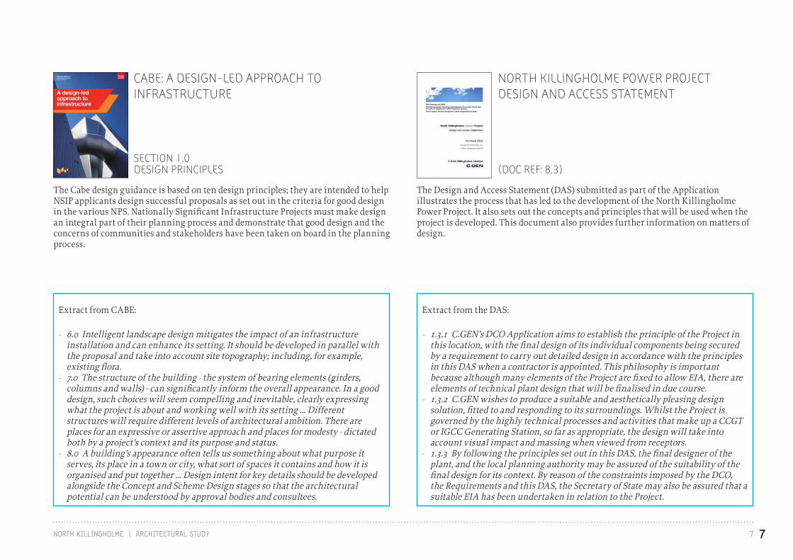
Extract from CABE:
- 6.0 Intelligent landscape design mitigates the impact of an infrastructure installation and can enhance its setting. It should be developed in parallel with the proposal and take into account site topography; including, for example, existing flora.
- 7.0 The structure of the building - the system of bearing elements (girders, columns and walls) - can significantly inform the overall appearance. In a good design, such choices will seem compelling and inevitable, clearly expressing what the project is about and working well with its setting ... Different structures will require different levels of architectural ambition. There are places for an expressive or assertive approach and places for modesty - dictated both by a project’s context and its purpose and status.
- 8.0 A building’s appearance often tells us something about what purpose it serves, its place in a town or city, what sort of spaces it contains and how it is organised and put together ... Design intent for key details should be developed alongside the Concept and Scheme Design stages so that the architectural potential can be understood by approval bodies and consultees.
CABE: A DESIGN-LED APPROACH TO INFRASTRUCTURE
NORTH KILLINGHOLME POWER PROJECTDESIGN AND ACCESS STATEMENT
The Cabe design guidance is based on ten design principles; they are intended to help NSIP applicants design successful proposals as set out in the criteria for good design in the various NPS. Nationally Significant Infrastructure Projects must make design an integral part of their planning process and demonstrate that good design and the concerns of communities and stakeholders have been taken on board in the planning process.
The Design and Access Statement (DAS) submitted as part of the Application illustrates the process that has led to the development of the North Killingholme Power Project. It also sets out the concepts and principles that will be used when the project is developed. This document also provides further information on matters of design.
SECTION 1.0DESIGN PRINCIPLES (DOC REF: 8.3)
7
8 NORTH KILLINGHOLME | ARCHITECTURAL STUDY
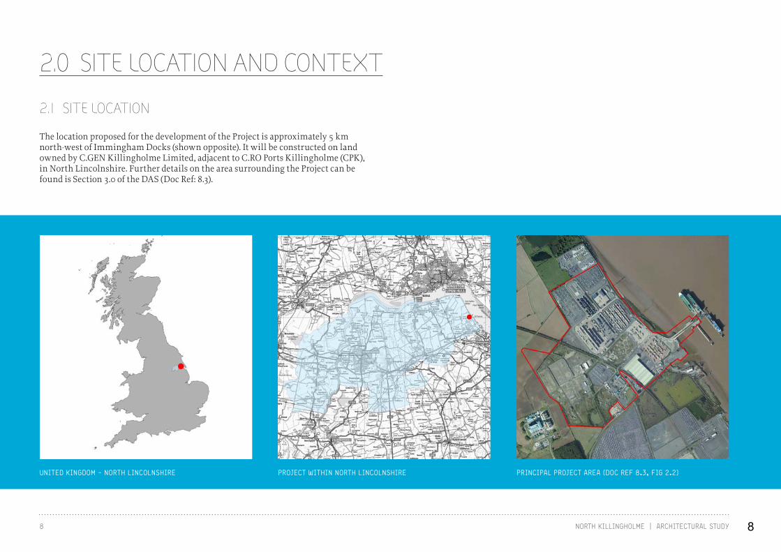
2.0 SITE LOCATION AND CONTEXT
UNITED KINGDOM - NORTH LINCOLNSHIRE PROJECT WITHIN NORTH LINCOLNSHIRE PRINCIPAL PROJECT AREA (DOC REF 8.3, FIG 2.2)
The location proposed for the development of the Project is approximately 5 km north-west of Immingham Docks (shown opposite). It will be constructed on land owned by C.GEN Killingholme Limited, adjacent to C.RO Ports Killingholme (CPK), in North Lincolnshire. Further details on the area surrounding the Project can be found is Section 3.0 of the DAS (Doc Ref: 8.3).
2.1 SITE LOCATION
8
RIVER HUMBER
LINDSEY OIL REFINERY
HUMBER OIL REFINERY
CENTRICA CCGT
EONCCGT
SOUTH KILLINGHOLME
NORTHKILLINGHOLME
EAST HALTON
C.RO PORTS KILLINGHOLME
RAILWAY
ABLE
IMMINGHAM DOCKS
PRINCIPAL PROJECT AREA
OPERATIONS AREA
ABLE LOGISTICS PARK
(ALP)
ABLE MARINE ENERGY PARK
(AMEP)
HUMBER ROAD A160 MANBY ROAD A1173EAST H
ALTON ROAD
DISUSED RAILWAY
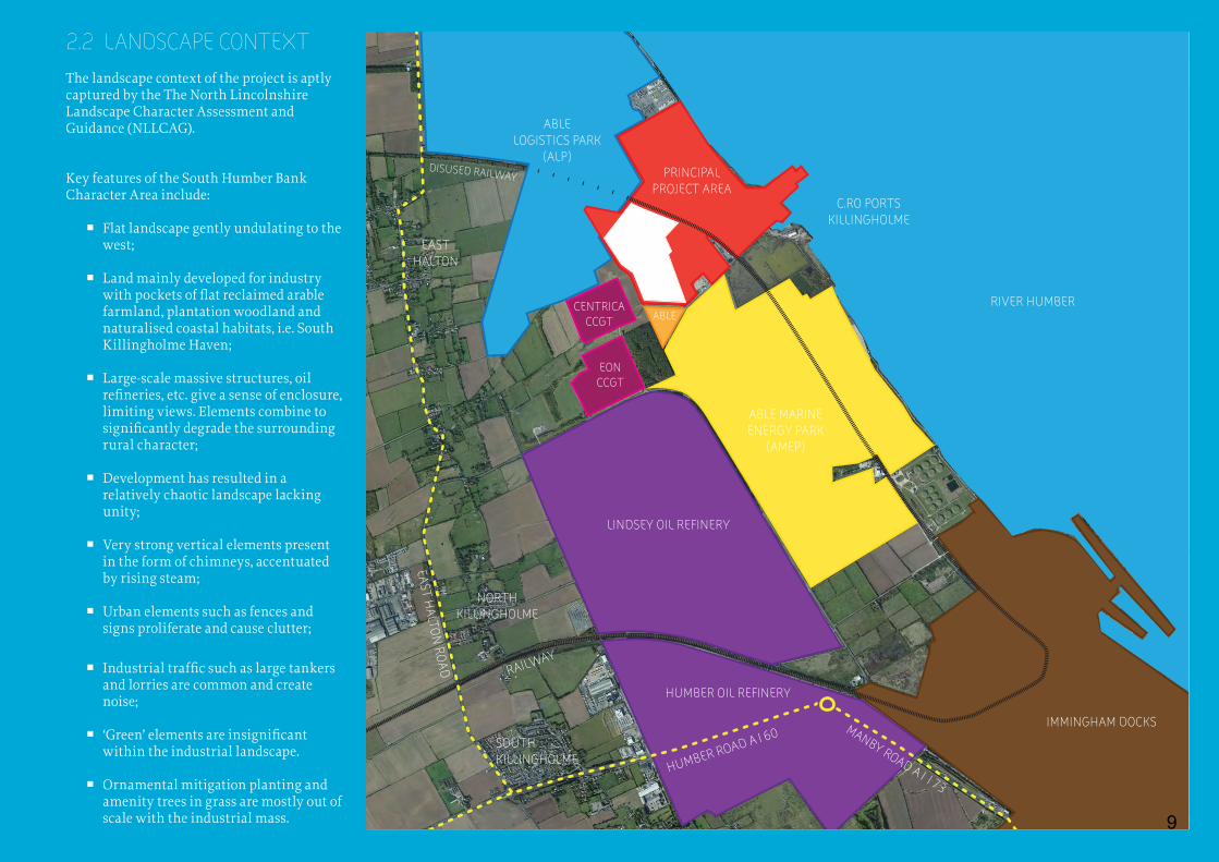
2.2 LANDSCAPE CONTEXTThe landscape context of the project is aptly captured by the The North Lincolnshire Landscape Character Assessment and Guidance (NLLCAG).
Key features of the South Humber Bank Character Area include:
� Flat landscape gently undulating to the west;
� Land mainly developed for industry with pockets of flat reclaimed arable farmland, plantation woodland and naturalised coastal habitats, i.e. South Killingholme Haven;
� Large-scale massive structures, oil refineries, etc. give a sense of enclosure, limiting views. Elements combine to significantly degrade the surrounding rural character;
� Development has resulted in a relatively chaotic landscape lacking unity;
� Very strong vertical elements present in the form of chimneys, accentuated by rising steam;
� Urban elements such as fences and signs proliferate and cause clutter;
� Industrial traffic such as large tankers and lorries are common and create noise;
� ‘Green’ elements are insignificant within the industrial landscape.
� Ornamental mitigation planting and amenity trees in grass are mostly out of scale with the industrial mass. 9
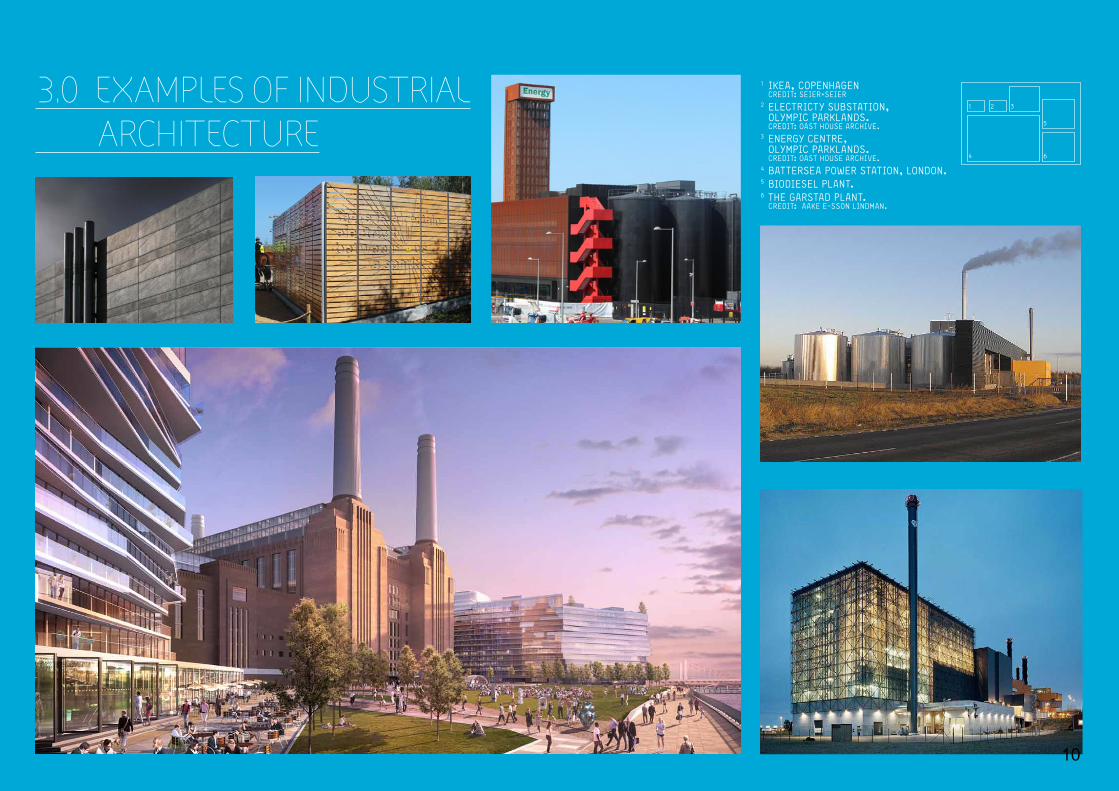
1 IKEA, COPENHAGEN CREDIT: SEIER+SEIER2 ELECTRICTY SUBSTATION, OLYMPIC PARKLANDS. CREDIT: OAST HOUSE ARCHIVE.3 ENERGY CENTRE, OLYMPIC PARKLANDS. CREDIT: OAST HOUSE ARCHIVE.4 BATTERSEA POWER STATION, LONDON.5 BIODIESEL PLANT.6 THE GARSTAD PLANT. CREDIT: AAKE E-SSON LINDMAN.
6 BATTERSEA POWER STATION DESIGN AND ACCESS STATEMENT JuLy 2011
LDA-DESIGN / EXTERIOR ARCHITECTURE1.0 INTRODuCTION
OuTLINE APPLICATION MASTERPLAN VIEW LOOkING WESTWARDS ALONG THE POWER STATION PARk
1
4 6
5
2 33.0 EXAMPLES OF INDUSTRIAL ARCHITECTURE
10
11NORTH KILLINGHOLME | ARCHITECTURAL STUDY
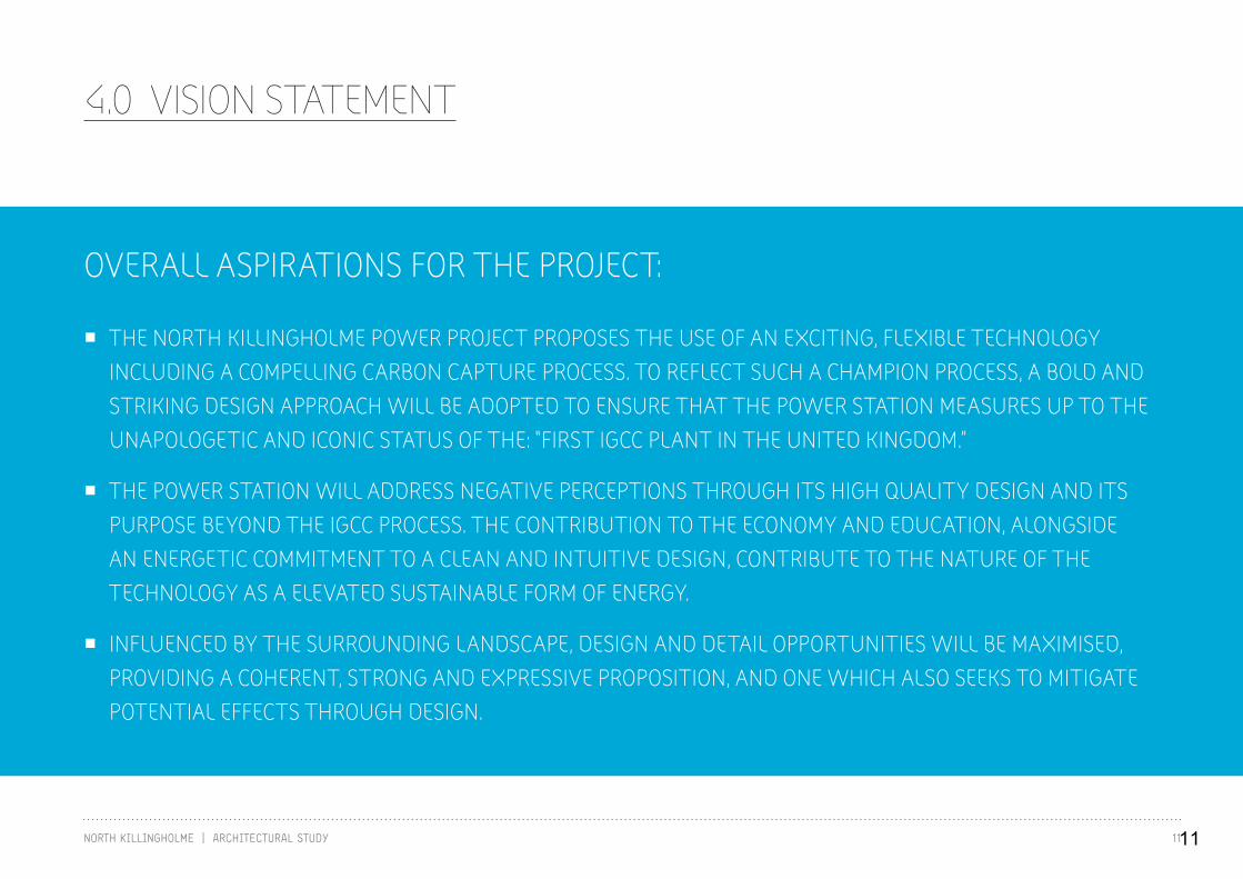
4.0 VISION STATEMENT
OVERALL ASPIRATIONS FOR THE PROJECT:
� THE NORTH KILLINGHOLME POWER PROJECT PROPOSES THE USE OF AN EXCITING, FLEXIBLE TECHNOLOGY INCLUDING A COMPELLING CARBON CAPTURE PROCESS. TO REFLECT SUCH A CHAMPION PROCESS, A BOLD AND STRIKING DESIGN APPROACH WILL BE ADOPTED TO ENSURE THAT THE POWER STATION MEASURES UP TO THE UNAPOLOGETIC AND ICONIC STATUS OF THE: “FIRST IGCC PLANT IN THE UNITED KINGDOM.”
� THE POWER STATION WILL ADDRESS NEGATIVE PERCEPTIONS THROUGH ITS HIGH QUALITY DESIGN AND ITS PURPOSE BEYOND THE IGCC PROCESS. THE CONTRIBUTION TO THE ECONOMY AND EDUCATION, ALONGSIDE AN ENERGETIC COMMITMENT TO A CLEAN AND INTUITIVE DESIGN, CONTRIBUTE TO THE NATURE OF THE TECHNOLOGY AS A ELEVATED SUSTAINABLE FORM OF ENERGY.
� INFLUENCED BY THE SURROUNDING LANDSCAPE, DESIGN AND DETAIL OPPORTUNITIES WILL BE MAXIMISED, PROVIDING A COHERENT, STRONG AND EXPRESSIVE PROPOSITION, AND ONE WHICH ALSO SEEKS TO MITIGATE POTENTIAL EFFECTS THROUGH DESIGN.
11
5.0 OPERATIONAL PROCESS
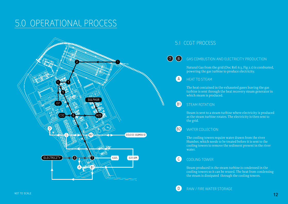
5.1 CCGT PROCESS
NOT TO SCALE
A HEAT TO STEAM
The heat contained in the exhausted gases leaving the gas turbine is sent through the heat recovery steam generator in which steam is produced.
B1 STEAM ROTATION
Steam is sent to a steam turbine where electricity is produced as the steam turbine rotates. The electricity is then sent to the grid.
C COOLING TOWER
Steam produced in the steam turbine is condensed in the cooling towers so it can be reused. The heat from condensing the steam is dissipated through the cooling towers.
D RAW / FIRE WATER STORAGE
87 GAS COMBUSTION AND ELECTRICITY PRODUCTION
Natural Gas from the grid (Doc Ref: 6.3, Fig 2.1) is combusted, powering the gas turbine to produce electricity.
WATER COLLECTION
The cooling towers require water drawn from the river Humber, which needs to be treated before it is sent to the cooling towers to remove the sediment present in the river water.
B2
12

13NORTH KILLINGHOLME | ARCHITECTURAL STUDY
5.2 IGCC PROCESS
COMBUSTION
The gasficiation process ends, and the clean syngas is sent to the gas turbine where it is combusted.
1 5TRANSPORT TO SITE
The solid fuel comes into the plant either by rail or by barge/pipe conveyor.
SYNGAS
Syngas is produced in the gasifier, which is sent to the syngas treatment block (containing the scrubber, shift reactor, the syngas coolant and condensate separator) to be cleaned.
2 6STORAGE
The solid fuel is placed inside a covered fuel storage area.
PURIFICATION
The syngas is then sent to the acid gas removal in which H2S and Carbon Dioxide (CO2) can be removed. The Hydrogen Sulfide (H2S) that is removed in the scrubbers is sent to the sulphur recovery and tail gas treatment plant, where it is transformed into pure sulphur.
3 A B1 B2 C D
7
MILLING AND PRESSURISATION
The solid fuel is sent to the coal milling and drying installation where it is milled and pressurised.
CCGT PROCESS
4 8GASFICIATION
It is then sent to the gasification vessel, which is the heart of the gasification plant. The pressurised solid fuel is injected together with compressed Oxygen (O2) from the air separation unit and the gasification process takes place in the gasifier.
ELECTRICITY PRODUCTION
Combustion makes the gas turbine rotate, producing electricity in the electrical generator.
Note: Building reference numbers can be found in Doc Ref: 6.3, Figure 3.1.
SOLID FUEL SYNGAS COMBUSTION ELECTRICITY
13
14 NORTH KILLINGHOLME | ARCHITECTURAL STUDY
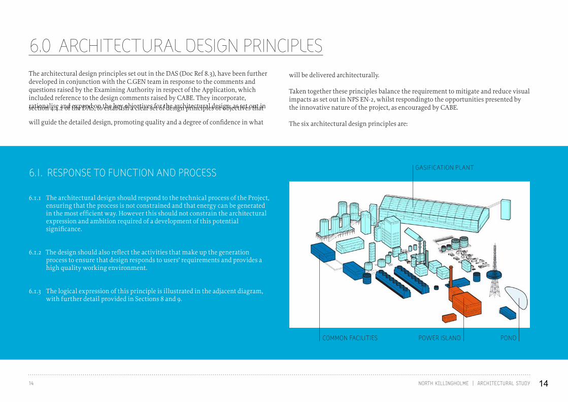
6.0 ARCHITECTURAL DESIGN PRINCIPLESThe architectural design principles set out in the DAS (Doc Ref 8.3), have been further developed in conjunction with the C.GEN team in response to the comments and questions raised by the Examining Authority in respect of the Application, which included reference to the design comments raised by CABE. They incorporate, rationalise and expand on the key objectives for the architectural design, as set out in section 4.4.2 of the DAS, to establish a clear set of design principles or objectives that
will guide the detailed design, promoting quality and a degree of confidence in what
will be delivered architecturally.
Taken together these principles balance the requirement to mitigate and reduce visual impacts as set out in NPS EN-2, whilst respondingto the opportunities presented by the innovative nature of the project, as encouraged by CABE.
The six architectural design principles are:
6.1. RESPONSE TO FUNCTION AND PROCESS
POWER ISLANDCOMMON FACILITIES
GASIFICATION PLANT
POND
6.1.1 The architectural design should respond to the technical process of the Project, ensuring that the process is not constrained and that energy can be generated in the most efficient way. However this should not constrain the architectural expression and ambition required of a development of this potential significance.
6.1.2 The design should also reflect the activities that make up the generation process to ensure that design responds to users’ requirements and provides a high quality working environment.
6.1.3 The logical expression of this principle is illustrated in the adjacent diagram, with further detail provided in Sections 8 and 9.
14
15NORTH KILLINGHOLME | ARCHITECTURAL STUDY
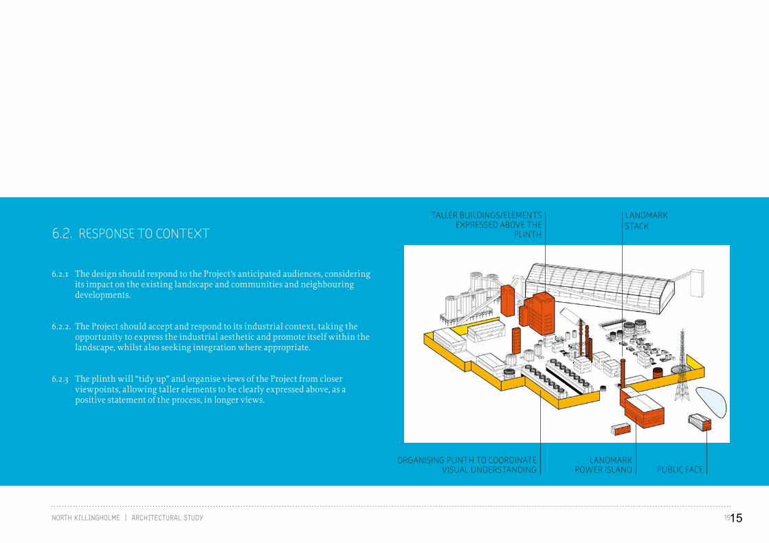
6.2. RESPONSE TO CONTEXT
6.2.1 The design should respond to the Project’s anticipated audiences, considering its impact on the existing landscape and communities and neighbouring developments.
6.2.2. The Project should accept and respond to its industrial context, taking the opportunity to express the industrial aesthetic and promote itself within the landscape, whilst also seeking integration where appropriate.
6.2.3 The plinth will “tidy up” and organise views of the Project from closer viewpoints, allowing taller elements to be clearly expressed above, as a positive statement of the process, in longer views.
PUBLIC FACELANDMARK
POWER ISLANDORGANISING PLINTH TO COORDINATE
VISUAL UNDERSTANDING
TALLER BUILDINGS/ELEMENTS EXPRESSED ABOVE THE
PLINTH
LANDMARKSTACK
15
16 NORTH KILLINGHOLME | ARCHITECTURAL STUDY
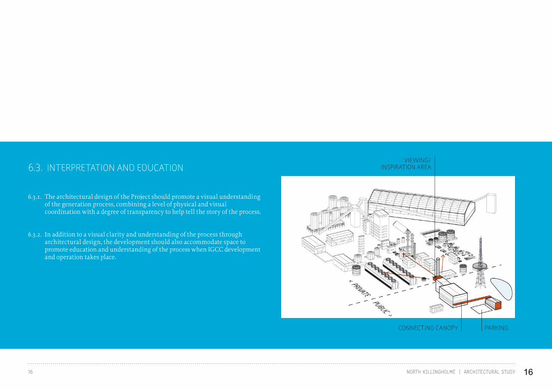
6.3. INTERPRETATION AND EDUCATION
6.3.1. The architectural design of the Project should promote a visual understanding of the generation process, combining a level of physical and visual coordination with a degree of transparency to help tell the story of the process.
6.3.2. In addition to a visual clarity and understanding of the process through architectural design, the development should also accommodate space to promote education and understanding of the process when IGCC development and operation takes place.
VIEWING/INSPIRATION AREA
PARKINGCONNECTING CANOPY
16

17NORTH KILLINGHOLME | ARCHITECTURAL STUDY
6.4. MASSING AND SCALE
6.4.1. The design should provide visual massing that supports the interpretation and visual understanding of the process, through the coordination and grouping of development.
6.4.2. The scale of development should reflect the activities and process contained within the Project whilst still enabling the visual coordination, hierarchy and grouping required to meet the other design principles.
HUMAN SCALE MASSING AND CANOPY STRUCTURE
LARGER SCULPTURAL ELEMENTS DEFINE THEMSELVES
POWER PLANT MASSING STACK TO FORM LANDMARK
PLINTH LEVEL TO COORDINATE THE ‘HEART’ OF THE DEVELOPMENT AND FRAME TALLER ELEMENTS
17
18 NORTH KILLINGHOLME | ARCHITECTURAL STUDY
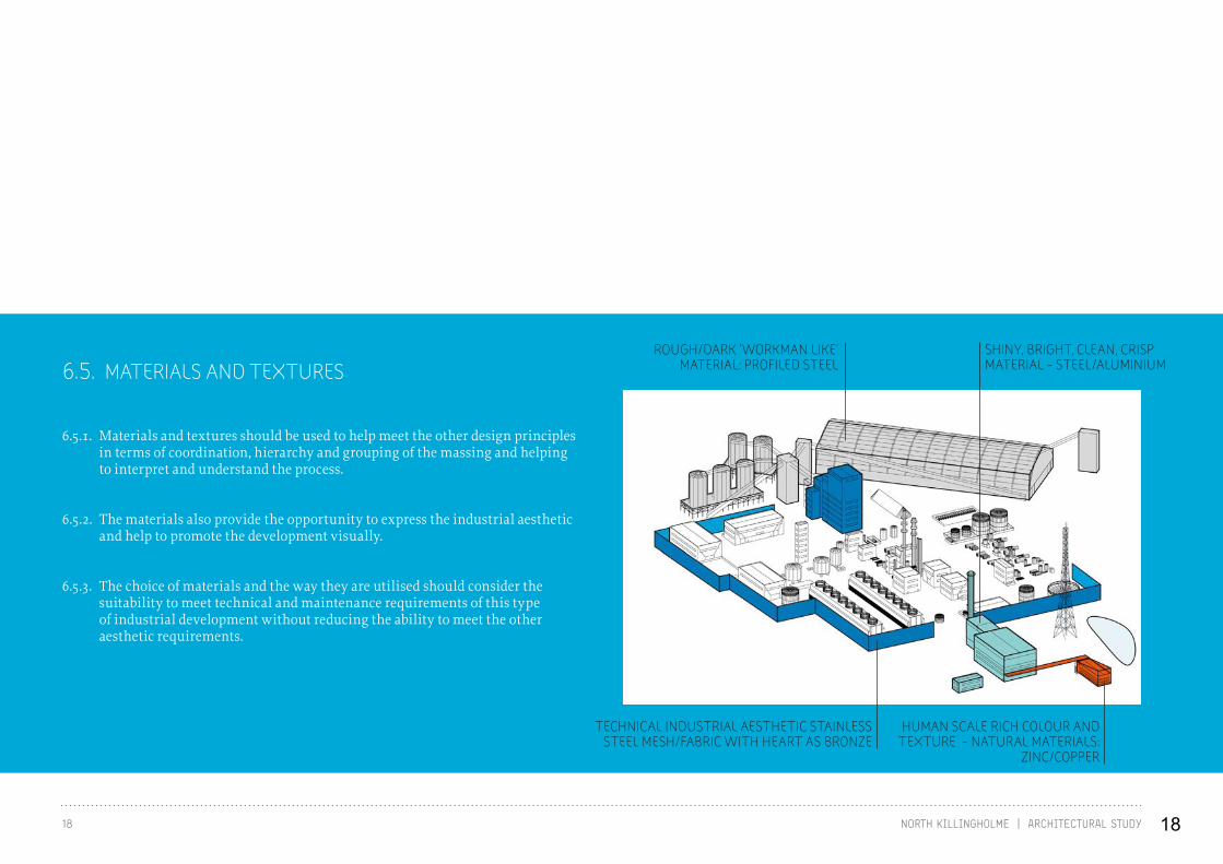
6.5. MATERIALS AND TEXTURES
6.5.1. Materials and textures should be used to help meet the other design principles in terms of coordination, hierarchy and grouping of the massing and helping to interpret and understand the process.
6.5.2. The materials also provide the opportunity to express the industrial aesthetic and help to promote the development visually.
6.5.3. The choice of materials and the way they are utilised should consider the suitability to meet technical and maintenance requirements of this type of industrial development without reducing the ability to meet the other aesthetic requirements.
HUMAN SCALE RICH COLOUR AND TEXTURE - NATURAL MATERIALS:
ZINC/COPPER
ROUGH/DARK ‘WORKMAN LIKE’ MATERIAL: PROFILED STEEL
SHINY, BRIGHT, CLEAN, CRISP MATERIAL - STEEL/ALUMINIUM
TECHNICAL INDUSTRIAL AESTHETIC STAINLESS STEEL MESH/FABRIC WITH HEART AS BRONZE
18
19NORTH KILLINGHOLME | ARCHITECTURAL STUDY
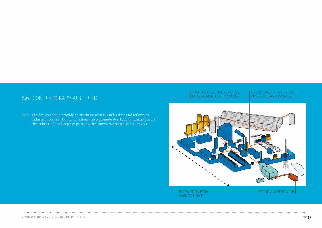
6.6. CONTEMPORARY AESTHETIC
6.6.1. The design should provide an aesthetic which is of its time and reflects its industrial context, but which should also promote itself as a landmark part of the industrial landscape, expressing the innovative nature of the Project.
STAND ALONE COLOUR
USE OF COLOUR TO HIGHLIGHT PIPE ROUTE AND PROCESS
SCULPTURAL ELEMENTS - SILOS/TANKS - STAND OUT IN COLOUR
GRADUATION FROM ‘DARK TO LIGHT’
19
20 NORTH KILLINGHOLME | ARCHITECTURAL STUDY
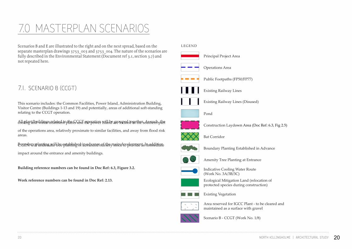
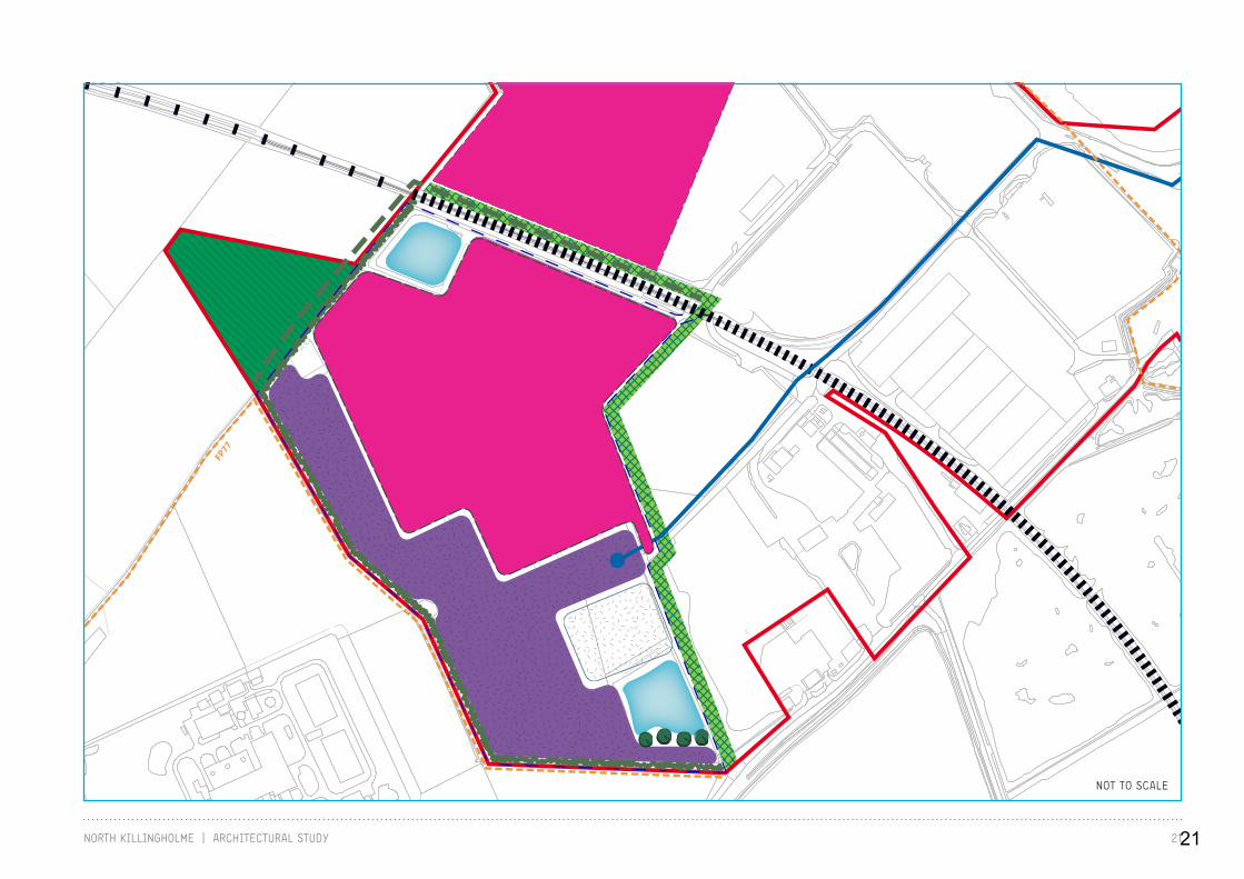
7.0 MASTERPLAN SCENARIOS
7.1. SCENARIO B (CCGT)
Scenarios B and E are illustrated to the right and on the next spread, based on the separate masterplan drawings 3753_003 and 3753_004. The nature of the scenarios are fully described in the Environmental Statement (Document ref 3.1, section 3.7) and not repeated here.
This scenario includes: the Common Facilities, Power Island, Administration Building, Visitor Centre (Buildings 1-13 and 19) and potentially, areas of additional soft-standing relating to the CCGT operation.
All plant/buildings related to the CCGT operation will be grouped together. As such, the cooling and water treatment plants and the power island are located in the southern part
of the operations area, relatively proximate to similar facilities, and away from flood risk areas.
Boundary planting will be established in advance of the main development. In addition C.GEN will undertake tree planting of advanced nursery stock to provide an immediate
impact around the entrance and amenity buildings.
Building reference numbers can be found in Doc Ref: 6.3, Figure 3.2.
Work reference numbers can be found in Doc Ref: 2.13.
LEGEND
Existing Vegetation
Area reserved for IGCC Plant - to be cleared and maintained as a surface with gravel
Scenario B - CCGT (Work No. 1/8)
Ecological Mitigation Land (relocation of protected species during construction)
Indicative Cooling Water Route (Work No. 3A/3B/3C)
Amenity Tree Planting at Entrance
Boundary Planting Established in Advance
Bat Corridor
Construction Laydown Area (Doc Ref: 6.3, Fig 2.5)
Pond
Existing Railway Lines
Existing Railway Lines (Disused)
Public Footpaths (FP50/FP77)
Operations Area
Principal Project Area
20
21NORTH KILLINGHOLME | ARCHITECTURAL STUDY
FP77
FP50
NOT TO SCALE
21
22 NORTH KILLINGHOLME | ARCHITECTURAL STUDY
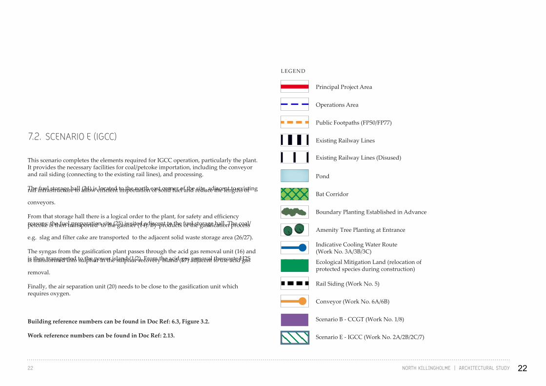
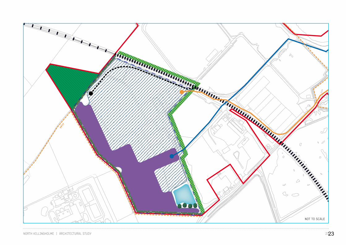
7.2. SCENARIO E (IGCC)
This scenario completes the elements required for IGCC operation, particularly the plant. It provides the necessary facilities for coal/petcoke importation, including the conveyor and rail siding (connecting to the existing rail lines), and processing.
The fuel storage hall (24) is located to the north east corner of the site, adjacent to existing rail infrastructure to allow efficient importation of solid fuel and reduce the lengths of
conveyors.
From that storage hall there is a logical order to the plant, for safety and efficiency reasons: the fuel preparation site (25) is sited adjacent to the fuel storage hall. The coal/petcoke is then transported to the gasifier (14). By-products of the gasification process
e.g. slag and filter cake are transported to the adjacent solid waste storage area (26/27).
The syngas from the gasification plant passes through the acid gas removal unit (16) and is then transported to the power island (1/2). From the acid gas removal the waste H2S is transformed into sulphur in the sulphur recovery island (17) adjacent to the acid gas
removal.
Finally, the air separation unit (20) needs to be close to the gasification unit which requires oxygen.
Building reference numbers can be found in Doc Ref: 6.3, Figure 3.2.
Work reference numbers can be found in Doc Ref: 2.13.
Ecological Mitigation Land (relocation of protected species during construction)
Rail Siding (Work No. 5)
Conveyor (Work No. 6A/6B)
Indicative Cooling Water Route (Work No. 3A/3B/3C)
Scenario B - CCGT (Work No. 1/8)
Scenario E - IGCC (Work No. 2A/2B/2C/7)
Amenity Tree Planting at Entrance
Boundary Planting Established in Advance
Bat Corridor
Pond
Existing Railway Lines
Existing Railway Lines (Disused)
Public Footpaths (FP50/FP77)
Operations Area
Principal Project Area
LEGEND
22
23NORTH KILLINGHOLME | ARCHITECTURAL STUDY
FP77
FP50
NOT TO SCALE
23

24 NORTH KILLINGHOLME | ARCHITECTURAL STUDY
8.0 APPLICATION OF DESIGN PRINCIPLES
8.1. POWER ISLAND AND PUBLIC FACEThese parts of the plant are located at the south end of the site, around the entrance, and present the public face of the Project. They are the culmination of the “dark to light” process (ie. a solid fuel such as coal is converted to gas and subsequently cleaned so that a relatively clean gas is being combusted). As described before, they would be positioned outside the organising plinth, allowing it to act as a screen between “public” and “private” parts of the plant. The key buildings in this area would be
expressed differently to one another, but unified by a clean and crisp approach to their architecture.
The Administration Building, although relatively small, would be the first building reached on entering the site. This is conceived as a “jewel-like” building, of human
scale, in a distinctive cladding (for example an anodised bronze colour, or patinated copper), with bold areas of glazing facing the site entrance and overlooking the pond. The choice of cladding finish would be repeated in a lightweight, elliptical mesh enclosure to the Power Island stack.
The cladding of the Administration Building would be extended in the form of a canopy to link to the main Power Island building. This would be also be clad in a metal, composite rainscreen system, but in silver to reflect the “clean” end of the process. Silvers, greys and bronzes are colours which can be found in the existing landscape, helping to integrate the Project in to the scene.
For IGCC operation Scenario E - this area also includes the tallest structure in the
The following pages illustrate the application of the principles, and design development of the Project. Massing, and the use of colour and materials, is illustrated. This is followed by elevational views of the project based upon figures 5.2A - 5.5A contained in the DAS, and views of the updated 3D model illustrated in Section 9.0 of this document. This material demonstrates good industrial design, reflecting the desire to achieve a project of marked quality, as well as being an appropriate response to views, from either close or mid/longer distance locations. The architectural response reflects the nature of the project which includes buildings as well as collections of process equipment, grouped together. The illustrative material included in this Study all comply with the restrictions upon building dimensions contained in
the Application for the Project.
This Architectural Study takes forward the proposals for colours and materials referred to in the DAS. The “dark to light” approach, which reflects the clean coal, gasification technology is intended as a positive statement of intent for the Project and will be reflected by the choice of materials and colours. In addition, drawing on hues in the landscape, the proposals aid the integration of the Project into the landscape, whilst also sending out clear statements relating to the innovative nature of the project by the selective use of bold colours for certain elements.
Project, the skeletal Flare Stack. Whilst this cannot be enclosed or architecturally “treated” for technical reasons, it does provide another opportunity for expression as part of a lighting scheme.
24

1 CHERRY COBB SAND ROAD - VIEWPOINT 13 / FIGURE 9.23 / DOC REF 6.3
2 SILVER ANODISED CLADDING - ODEON, TROWBRIDGE, UK 3 BRONZE MESH 4 MESH - UNIVERSITY OF LIVERPOOL, UK
25
26 NORTH KILLINGHOLME | ARCHITECTURAL STUDY
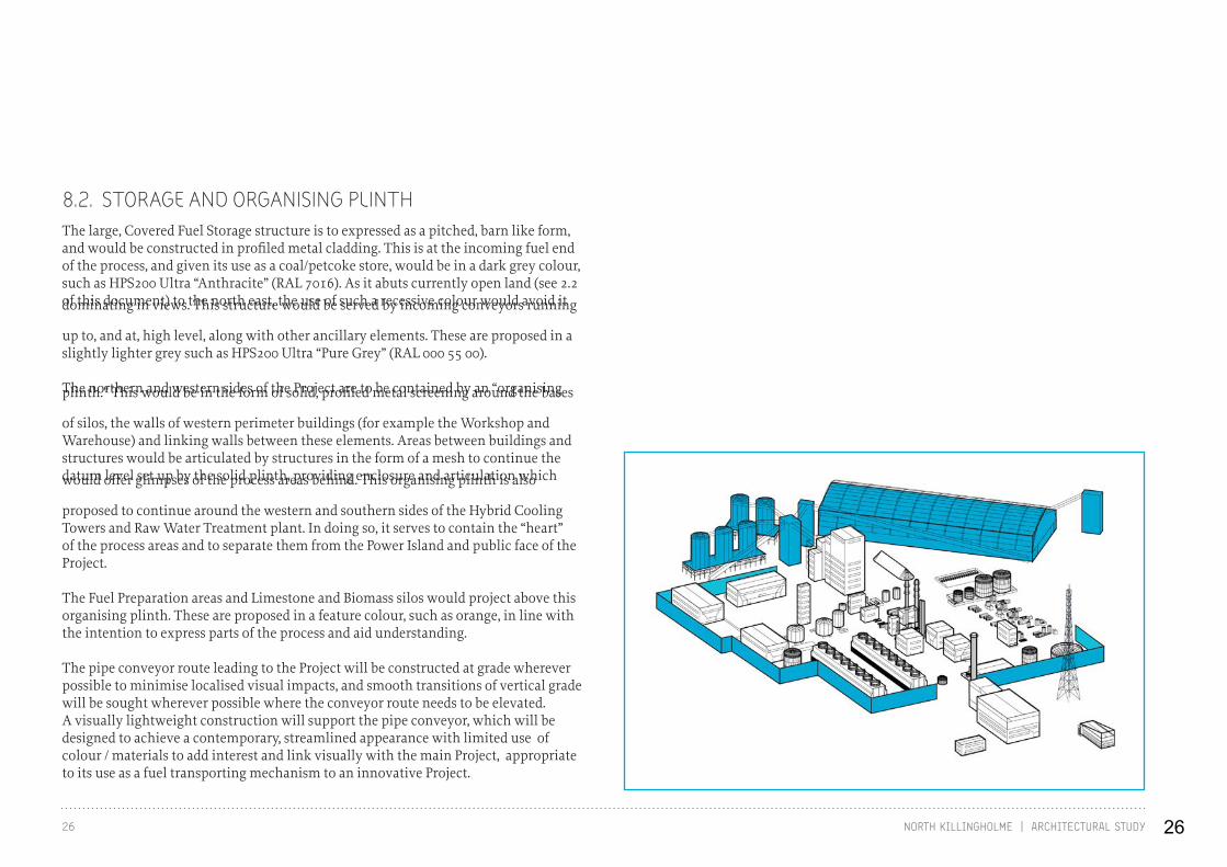
8.2. STORAGE AND ORGANISING PLINTHThe large, Covered Fuel Storage structure is to expressed as a pitched, barn like form, and would be constructed in profiled metal cladding. This is at the incoming fuel end of the process, and given its use as a coal/petcoke store, would be in a dark grey colour, such as HPS200 Ultra “Anthracite” (RAL 7016). As it abuts currently open land (see 2.2 of this document) to the north east, the use of such a recessive colour would avoid it dominating in views. This structure would be served by incoming conveyors running
up to, and at, high level, along with other ancillary elements. These are proposed in a slightly lighter grey such as HPS200 Ultra “Pure Grey” (RAL 000 55 00).
The northern and western sides of the Project are to be contained by an “organising plinth.” This would be in the form of solid, profiled metal screening around the bases
of silos, the walls of western perimeter buildings (for example the Workshop and Warehouse) and linking walls between these elements. Areas between buildings and structures would be articulated by structures in the form of a mesh to continue the datum level set up by the solid plinth, providing enclosure and articulation which would offer glimpses of the process areas behind. This organising plinth is also
proposed to continue around the western and southern sides of the Hybrid Cooling Towers and Raw Water Treatment plant. In doing so, it serves to contain the “heart” of the process areas and to separate them from the Power Island and public face of the Project.
The Fuel Preparation areas and Limestone and Biomass silos would project above this organising plinth. These are proposed in a feature colour, such as orange, in line with the intention to express parts of the process and aid understanding.
The pipe conveyor route leading to the Project will be constructed at grade wherever possible to minimise localised visual impacts, and smooth transitions of vertical grade will be sought wherever possible where the conveyor route needs to be elevated. A visually lightweight construction will support the pipe conveyor, which will be designed to achieve a contemporary, streamlined appearance with limited use of colour / materials to add interest and link visually with the main Project, appropriate to its use as a fuel transporting mechanism to an innovative Project.
26
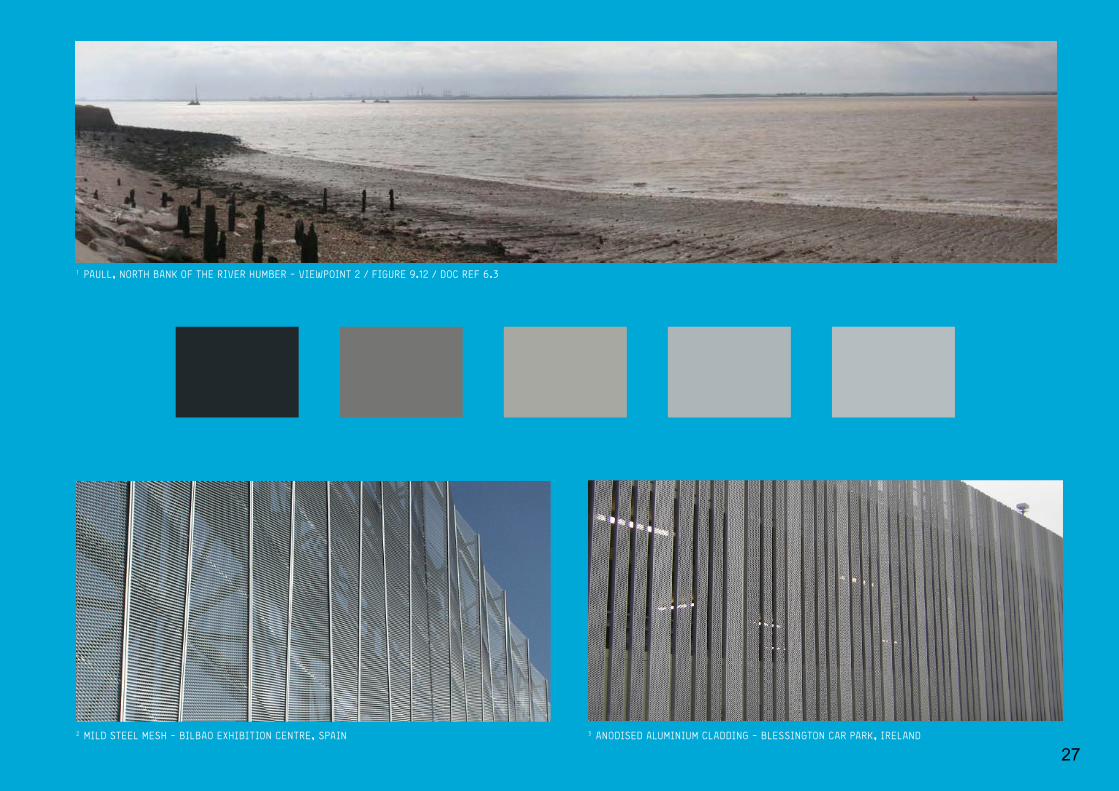
1 PAULL, NORTH BANK OF THE RIVER HUMBER - VIEWPOINT 2 / FIGURE 9.12 / DOC REF 6.3
2 MILD STEEL MESH - BILBAO EXHIBITION CENTRE, SPAIN 3 ANODISED ALUMINIUM CLADDING - BLESSINGTON CAR PARK, IRELAND
27
28 NORTH KILLINGHOLME | ARCHITECTURAL STUDY
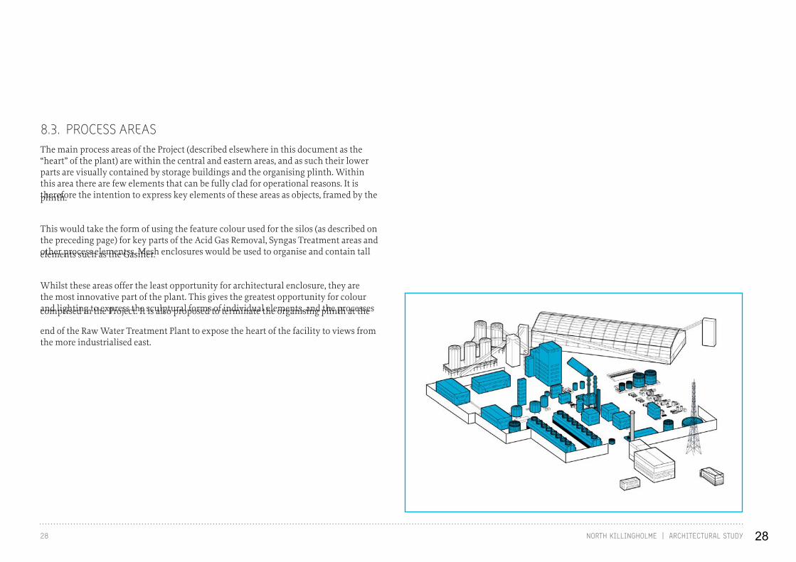
8.3. PROCESS AREASThe main process areas of the Project (described elsewhere in this document as the “heart” of the plant) are within the central and eastern areas, and as such their lower parts are visually contained by storage buildings and the organising plinth. Within this area there are few elements that can be fully clad for operational reasons. It is therefore the intention to express key elements of these areas as objects, framed by the plinth.
This would take the form of using the feature colour used for the silos (as described on the preceding page) for key parts of the Acid Gas Removal, Syngas Treatment areas and other process elementss. Mesh enclosures would be used to organise and contain tall elements such as the Gasifier.
Whilst these areas offer the least opportunity for architectural enclosure, they are the most innovative part of the plant. This gives the greatest opportunity for colour and lighting to express the sculptural forms of individual elements, and the processes comprised in the Project. It is also proposed to terminate the organising plinth at the
end of the Raw Water Treatment Plant to expose the heart of the facility to views from the more industrialised east.
28
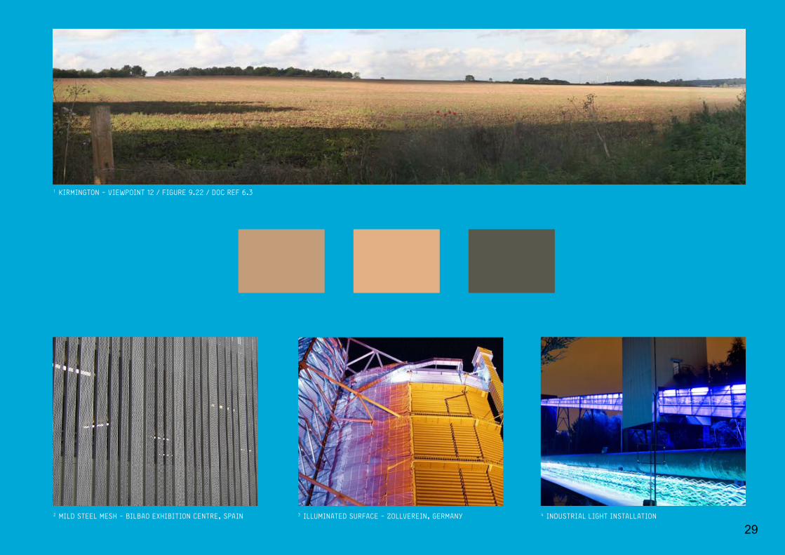
1 KIRMINGTON - VIEWPOINT 12 / FIGURE 9.22 / DOC REF 6.3
2 MILD STEEL MESH - BILBAO EXHIBITION CENTRE, SPAIN 3 ILLUMINATED SURFACE - ZOLLVEREIN, GERMANY 4 INDUSTRIAL LIGHT INSTALLATION
29
30 NORTH KILLINGHOLME | ARCHITECTURAL STUDY
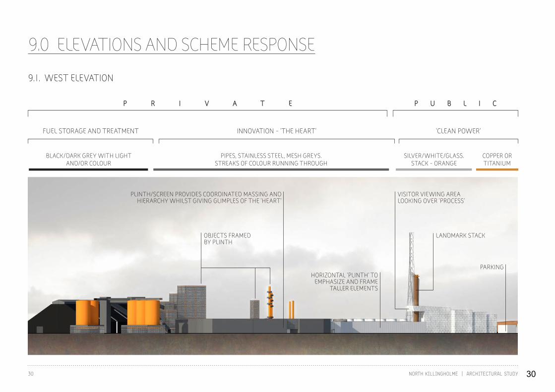
9.0 ELEVATIONS AND SCHEME RESPONSE
LANDMARK STACKOBJECTS FRAMED BY PLINTH
HORIZONTAL ‘PLINTH’ TO EMPHASIZE AND FRAME
TALLER ELEMENTS
VISITOR VIEWING AREA LOOKING OVER ‘PROCESS’
PARKING
PLINTH/SCREEN PROVIDES COORDINATED MASSING AND HIERARCHY WHILST GIVING GLIMPLES OF THE ‘HEART’
P R I V A T E P U B L I C
COPPER OR TITANIUM
SILVER/WHITE/GLASS.STACK - ORANGE
BLACK/DARK GREY WITH LIGHTAND/OR COLOUR
PIPES, STAINLESS STEEL, MESH GREYS.STREAKS OF COLOUR RUNNING THROUGH
FUEL STORAGE AND TREATMENT ‘CLEAN POWER’INNOVATION - ‘THE HEART’
9.1. WEST ELEVATION
30

31NORTH KILLINGHOLME | ARCHITECTURAL STUDY
LANDMARK STACK
SIMPLY CLAD HANGAR WITH PROCESS ARTICULATED
ALONG RIDGELINE
CANOPY STRUCTURE TO MARK VISITOR ROUTE AND TO PULL PUBLIC END TOGETHER.
VISITORS GALLERY
GLAZED FACADE OVERLOOKING LAKE/POND
ENTRY ROAD
NATURALLY CLAD BUILDING - WITH GLASS‘JEWEL LIKE’
THE ‘HEART’ - THE INNOVATIVE PART OF THE PROCESS EXPOSED FOR ALL TO SEE
RIDGELINE
P R I V A T EP U B L I C
PUBLIC FACE INNOVATION - ‘THE HEART’ FUEL STORAGE AND TREATMENT
COPPER OR TITANIUM
SILVER/WHITE/GLASS.STACK - ORANGE
PIPES, STAINLESS STEEL, MESH GREYS.STREAKS OF COLOUR RUNNING THROUGH
BLACK/DARK GREY WITH LIGHTAND/OR COLOUR
9.2. EAST ELEVATION
31

32 NORTH KILLINGHOLME | ARCHITECTURAL STUDY
CLEAN/CRISPSTYLE
MESH SCREEN PLINTH TO ‘BOOK END’ /‘WRAP AROUND HEART’
GASIFIER PARTIALLY CLAD
P R I V A T E P U B L I C
‘CLEAN POWER’
FUEL STORAGE AND TREATMENT
THE HEART (INNOVATIVE CHEMICAL PROCESS)
LANDMARK STACK
RIDGELINE
9.3. SOUTH ELEVATION
32

33NORTH KILLINGHOLME | ARCHITECTURAL STUDY
CLEAN/CRISP ARCHITECTURE
P R I V A T E
P U B L I C
‘CLEAN POWER’
FUEL STORAGE AND TREATMENT
THE HEART (INNOVATIVE CHEMICAL PROCESS)
SIMPLY CLAD HANGAR WITH PROCESS ARTICULATED
ALONG RIDGELINE
LANDMARK STACK
9.4. NORTH ELEVATION
33

34 NORTH KILLINGHOLME | ARCHITECTURAL STUDY 34

9.4. VIEW OF THE 3D MODEL
35

36 NORTH KILLINGHOLME | ARCHITECTURAL STUDY
APPENDIX 1.0
Masterplan Vision for area C.GEN supports this approach, but considers that formulating a Vision or Strategy for the area is the role of the local authority. As a major development this Project would contribute to the likely aspirations of such a vision/strategy, as C.GEN aligns itself to the suggested aims as set out by CABE. These include education; innovation; joined up thinking; sustainability; and economic growth. These factors have shaped the Project as explained in this document.
Tourist destination C.GEN recognises that the plant is of potential interest to those interested in energy and industrial projects that are innovative and of ground breaking nature. Nevertheless C.GEN would not view the facility as one which would be of significant tourist interest, but rather a niche location for a relatively small number of people. The masterplan allows for this likelihood to include public access to certain areas including a visitor centre (in IGCC operational mode) which will provide an elevated viewpoint into the innovative part of the complex, and interpretation and explanation of the plant , sustainable energy production and the company.
Educational resource/facility An educational facility can be incorporated to accommodate all ages, with interpretation of the energy generation processes and the history of the site. In CCGT mode (Scenario B) the Project represents a relatively conventional type generating station and thus the provision of a visitor facility would be disproportionate.
Address negative perceptions C.GEN is committed to a high quality, good design which will contribute positively in a number of ways- its clean credentials, the commitment to good design, education , and contribution to the economy are all positive indicators.
Bold approach to design C.GEN recognises this is an exciting Project, which is important to the UK. C.GEN agrees the design should reflect that fact and not be apologetic. This document explains the approach to be adopted, how the design reflects the context and the process in an appropriate manner reflecting the significance and innovative nature of the plant. The design is bold, clean and intuitive, reflecting the nature of the technology as a forward facing sustainable form of energy.
Tabular response to CABE queries – DA2/01.
36

37NORTH KILLINGHOLME | ARCHITECTURAL STUDY
Maximise green space;Use existing vegetation to provide a setting
The nature of the process dictates a sequential and dense development, precluding wide landscape corridors through the development. There are constraints on the layout of the Project in relation to provision of landscape corridors and the northern pond is to be removed in Scenario E. The entrance area and existing southern pond will be an important area for maximizing Green Infrastructure benefits in landscape and biodiversity terms. This, coupled with perimeter screen planting, will ensure the site landscape is integrated with the existing landscape and forms a setting for the plant.
Opportunities for art The proposals for colour and materials and lighting will be capable of providing a basis for artists to be involved in the detail design.
Appearance of plant in long distance with reference to colour and massing
The use of colour, massing and cladding provides the basis for integrating the Project into the landscape, firmly grounding it, and ensures the Project appears as a unified whole with a clear purpose. Boundary planting and existing vegetation helps to integrate the development in views, with the main structures clearly visible, with clean lines.
Design opportunity for flare stack The ecological constraints in the surrounding area and thermal/structural requirements of the Project offer little scope to change the main flare stack. It is designed as a structurally light pylon, standing away from the main plant. The main stack of the Power Island provides more scope for a strong, expressive stack to form a focus for the main built development, thereby allowing the lighter flare stack to be more recessive and separate.
Lighting proposals Exciting use of light to highlight key structures and use of coloured lighting is capable of being used to highlight and express the main built forms and to highlight key features. Aviation safety lighting of the flare stack will be required, as well as ambient lighting to the Project in any event.
37

A 17 Minster Precincts Peterborough PE1 1XX United KingdomT +44 (0) 1733 310 471F +44 (0) 1733 553 661W www.lda-design.co.uk LDA Design Consulting LLP Registered No: OC307725 17 Minster Precincts, Peterborough PE1 1XX
38