
Appendix A – WDT1552 · Appendix A – QC11 Phase I 2 The Generating Facility consists of all...
38
Appendix A – WDT1552 Queue Cluster 11 Phase I Report January 15, 2019 This study has been completed in coordination with the California Independent System Operator Corporation (ISO) per Southern California Edison Company’s Wholesale Distribution Access Tariff (WDAT), Attachment I Generator Interconnection Procedures (GIP)
Transcript of Appendix A – WDT1552 · Appendix A – QC11 Phase I 2 The Generating Facility consists of all...

Appendix A – WDT1552
Queue Cluster 11 Phase I Report
January 15, 2019
This study has been completed in coordination with the California Independent System
Operator Corporation (ISO) per Southern California Edison Company’s Wholesale Distribution Access Tariff (WDAT), Attachment I Generator Interconnection Procedures (GIP)

Appendix A – QC11 Phase I ii
Interconnection Study Document History
No. Date Document Title Description of Document
1 1/15/19 Queue Cluster 11 Phase I Appendix A Report
Final Phase I interconnection study
report
Appendix A – QC11 Phase I iii
TABLE OF CONTENTS
A. Introduction .................................................................................................................................. 1
B. Study Assumptions ........................................................................................................................ 6
C. Technical requirements ................................................................................................................. 9
D. Reliability Standards, Study Criteria and Methodology ................................................................ 11
E. Power Flow Reliability Assessment Results .................................................................................. 12
F. Transient stability Evaluation ....................................................................................................... 16
G. Short‐Circuit Duty Results ............................................................................................................ 17
H. Deliverability Assessment Results ................................................................................................ 19
I. Interconnection Facilities, Network Upgrades, and Distribution Upgrades ................................... 19
J. Cost and Construction Duration Estimate ..................................................................................... 19
K. In‐Service Date and Commercial Operation Date Assessment ...................................................... 21
L. ADDITIONAL STUDY ANNOTATIONS ............................................................................................. 23
ATTACHMENTS Attachment 1: Interconnection Facilities, Network Upgrades, and Distribution Upgrades ...................... 27
Attachment 2: Escalated Cost and Time to Construct for Interconnection Facilities, Reliability Network
Upgrades, Delivery Network Upgrades, and Distribution Upgrades .......................................................... 28
Attachment 3: Allocation of Network Upgrades for Cost Estimates and Maximum Network Upgrade Cost
Responsibility .............................................................................................................................................. 29
Attachment 4: SCE’s Interconnection Handbook ....................................................................................... 30
Attachment 5: Short‐Circuit Duty Calculation Study Results ..................................................................... 32
Attachment 6: IC Provided Generating Facility Dynamic Data .................................................................. 33
Attachment 7 Subtransmission Assessment Report ................................................................................... 35

Appendix A – QC11 Phase I 1
A. INTRODUCTION the Interconnection Customer (IC), has
submitted a completed Interconnection Request (IR) to Southern California Edison (SCE), the Distribution Provider, for its proposed (Generating Facility).
In accordance with FERC approved SCE’s WDAT Attachment I Generator Interconnection Procedures (GIP), the Generating Facility was grouped with Queue Cluster 11 (QC11) Phase I projects to determine the impacts of the group as well as impacts of the Generating Facility on SCE’s Distribution System and the ISO Grid. An Area Report and, where applicable, a Subtransmission Assessment Report have been prepared separately identifying the combined impacts of all projects on the ISO Grid and to distribution facilities served out of the Goleta 66 kV Subtransmission System, respectively. This Appendix A report focuses only on the impacts or impact contributions of the Generating Facility. This report is not intended to supersede any contractual terms or conditions specified in a forthcoming Generator Interconnection Agreement (GIA). The report provides the following:
1. Distribution and transmission system impacts allocated to the Generating Facility.
2. System reinforcements or mitigation necessary to address the adverse impacts allocated to the Generating Facility under various system conditions.
3. A list of required facilities and a good faith estimate of the Generating Facility’s cost responsibility and time to construct1 these facilities. Such information is provided in Attachment 1 and Attachment 2 as separate documents in the Appendix A report package of the Generating Facility.
4. Identification of potential short circuit duty impacts to Affected Systems served from the
Subtransmission or Distribution System.
The Generating Facility encompasses energy storage equipment that triggered the need to analyze its charging impacts on SCE’s electric system. The analyses focused on the Charging Demand2 aspects of the Generating Facility and considered varying levels of system demand with minimal generation dispatch within the local distribution system. Consequently, the report also discloses the adequacy of SCE’s electric system to support the Generating Facility when operating in charging mode, identifies system limitations that may restrict the Generating Facility when operating in charging mode during certain demand conditions, and provides a high‐level explanation of potential exposure to the Generating Facility of charging restrictions on the electric system.
1 It should be noted that construction is only part of the duration of months specified in the study, which includes detailed engineering, licensing, and other
activities required to bring such facilities into service. These durations are from the execution of the GIA, receipt of: all required information, funding, and written authorization to proceed with design and engineering, procurement, and construction from the IC as will be specified in the GIA to commence the work.
2 Charging Demand: The flow of wholesale electric energy from the Distribution System solely to charge the storage component of the Eligible Customer’s Resource
from the Distribution System for later redelivery of such energy, net of Resource losses, to the Distribution System. Charging Demand does not include the
delivery of energy for purposes that are subject to the SCE’s retail tariff.

Appendix A – QC11 Phase I 2
The Generating Facility consists of all equipment and facilities comprising the IC’s generating facility to be located in , as disclosed by the IC in its IR, as
may have been amended during the Interconnection Study process, as summarized below:
Table A.1: Generation Facility General Information per the IR
Note: Detailed loss analysis used in defining net capability at high side of main
transformer bank and net capacity at the POI
The IC has requested, and the GIA will provide for, a total net capacity of as measured at the high‐side of the main step‐transformer(s) and at the POI. If the Generating Facility is capable of exceeding these values, the IC shall be required to install, own and maintain a control limiting device or, alternatively, by means of configuring the Generating Facility’s control system, as approved by SCE that will ensure the Generating Facility complies with these restrictions.
The Interconnection Facilities of the Generating Facility are illustrated in Figure A.1. While Figure A.2 illustrates the location of the Generating Facility. Additional Generating Facility information is provided in Table A.2

Appendix A – QC11 Phase I 3
Figure A.1: Generating Facility One‐Line Diagram

Appendix A – QC11 Phase I 4
Figure A.2: Generating Facility Location Map

Appendix A – QC11 Phase I 5
Table A.2: Additional Generating Facility General Information
Generating Facility Location
SCE’s Planning Area
Interconnection Voltage
POI
Number and Types of Generators
Requested Maximum Generating Facility Delivery at POI3
Generation Tie Line
Main Step‐Up Transformer(s) Main Transformers T1
Collector Equivalent
Pad‐Mount Transformer(s) Downstream of Main Transformer Bank T1
Generator Data Downstream of Main Transformer Bank T1
3 The MW output at the POI varies under different operating conditions. The IC is reminded that this value is tied to the generation tie‐line (gen‐tie) losses. The estimated Maximum Net Output value at POI and gen‐tie losses illustrated in Section E, are contingent upon the accuracy of the technical data provided by the IC, and are subject to change should the IC change its gen‐tie parameters during the detailed engineering and design phase of the Generating Facility. Please note that the Generating Facility shall not exceed the total net output of 54 MW at the POI.

Appendix A – QC11 Phase I 6
Generator Auxiliary Load and/or Station Light and Power
Voltage Regulation Devices Downstream of Main Transformer Bank T
Dynamic Models Used Downstream of Main Transformer Bank T
Deliverability Requested
Pro
In‐Service Date (ISD)
Initial Synchronization Date/Trial Operation
Commercial Operation Date (COD)
B. STUDY ASSUMPTIONS For detailed assumptions regarding the group cluster analysis, please refer to the QC11 Phase I Area Report. Below are the assumptions specific to the Generating Facility:
1. The Generating Facility was modeled as described in Table A.1 and A.2 above.
2. The facilities that will be installed by SCE and the IC are detailed in Attachment 1.
3. Roles and Responsibilities for Environmental Activities, Permits, and Licensing.
The assumptions for the Environmental Activities, Permits, and Licensing are as follows:
i. SCE Facilities
a. SCE’s Interconnection Facilities (IF’s), Reliability Network Upgrades (RNU’s), and Distribution Upgrades (DU’s) allocated to the Generating Facility:
SCE will perform all environmental studies and monitoring of all SCE internal substation construction activities.
SCE’s scope of work will require a California Public Utilities Commission (CPUC) license.
4 Such dates are specified in the Generating Facility’s IR. Actual ISD, Initial Synchronization Date, and COD will depend on licensing, engineering, detailed design, and construction requirements to interconnect the Generating Facility after the GIA has been executed and/or filed at Federal Energy Regulatory Commission (FERC) for acceptance.
Appendix A – QC11 Phase I 7
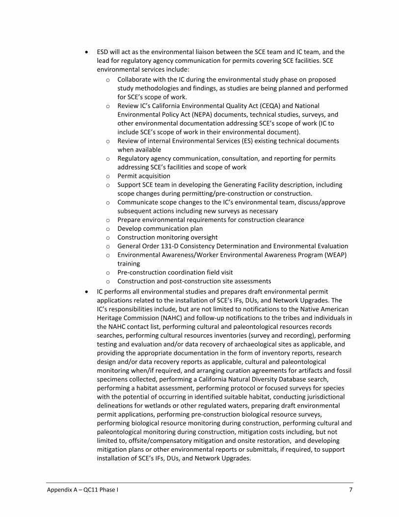
ESD will act as the environmental liaison between the SCE team and IC team, and the lead for regulatory agency communication for permits covering SCE facilities. SCE environmental services include:
o Collaborate with the IC during the environmental study phase on proposed study methodologies and findings, as studies are being planned and performed for SCE’s scope of work.
o Review IC’s California Environmental Quality Act (CEQA) and National Environmental Policy Act (NEPA) documents, technical studies, surveys, and other environmental documentation addressing SCE’s scope of work (IC to include SCE’s scope of work in their environmental document).
o Review of internal Environmental Services (ES) existing technical documents when available
o Regulatory agency communication, consultation, and reporting for permits addressing SCE’s facilities and scope of work
o Permit acquisition o Support SCE team in developing the Generating Facility description, including
scope changes during permitting/pre‐construction or construction. o Communicate scope changes to the IC’s environmental team, discuss/approve
subsequent actions including new surveys as necessary o Prepare environmental requirements for construction clearance o Develop communication plan o Construction monitoring oversight o General Order 131‐D Consistency Determination and Environmental Evaluation o Environmental Awareness/Worker Environmental Awareness Program (WEAP)
training o Pre‐construction coordination field visit o Construction and post‐construction site assessments
IC performs all environmental studies and prepares draft environmental permit applications related to the installation of SCE’s IFs, DUs, and Network Upgrades. The IC’s responsibilities include, but are not limited to notifications to the Native American Heritage Commission (NAHC) and follow‐up notifications to the tribes and individuals in the NAHC contact list, performing cultural and paleontological resources records searches, performing cultural resources inventories (survey and recording), performing testing and evaluation and/or data recovery of archaeological sites as applicable, and providing the appropriate documentation in the form of inventory reports, research design and/or data recovery reports as applicable, cultural and paleontological monitoring when/if required, and arranging curation agreements for artifacts and fossil specimens collected, performing a California Natural Diversity Database search, performing a habitat assessment, performing protocol or focused surveys for species with the potential of occurring in identified suitable habitat, conducting jurisdictional delineations for wetlands or other regulated waters, preparing draft environmental permit applications, performing pre‐construction biological resource surveys, performing biological resource monitoring during construction, performing cultural and paleontological monitoring during construction, mitigation costs including, but not limited to, offsite/compensatory mitigation and onsite restoration, and developing mitigation plans or other environmental reports or submittals, if required, to support installation of SCE’s IFs, DUs, and Network Upgrades.

Appendix A – QC11 Phase I 8
Prior to commencing work and during execution of work, the IC should collaborate and obtain ES concurrence on all work outlined above. Should the IC‐performed environmental studies, surveys, or monitoring not meet the Federal or State industry standards in accordance with Applicable Laws and Regulations, and as determined by ES, the IC shall be obligated to remedy deficiencies under SCE/ES’s direction, or ES shall undertake additional environmental studies, surveys, or monitoring at the sole expense of the IC. If these scenarios occur, the cost estimate must be updated to reflect the changes to the assumptions.
The estimated cost(s) provided in the Phase I study assumed that the IC will perform part of the environmental services scope of work (SOW) that would normally be performed by SCE for SCE‐owned IF, RNUs, and DUs, if applicable, to interconnect the Large Generating Facility. The IC shall provide SCE an itemized accounting record of the actual costs for work performed by the IC in a form acceptable to SCE. The IC acknowledges and accepts that these costs will be subject to an Interconnection Facilities Charge, a Distribution Facilities Charge, if applicable, and Income Tax Contribution Component (ITCC).
For further details on the environmental evaluation and permitting/licensing requirements for generation projects refer to Appendix K of the Area report.
4. Energy Storage Considerations:
With respect to charging, SCE currently offers “as available” service pursuant to the WDAT. Charging restrictions will be implemented through the use of Distributed Energy Resource Management System (DERMS), as applicable.
SCE’s Distribution Standards and Practices are in the process of being updated to address energy storage facilities. The proposed Plan of Service in this report may require changes to comply with SCE’s Distribution Standards and Practices.
This study assumes that the Generating Facility will include all equipment, software, appropriate controls, and other related equipment necessary to maintain the energy storage facility demand restriction per SCE’s requirements.
In order to ensure limits are communicated in a timely and reliable manner, the IC is responsible for providing reliable communication between the Generating Facility and SCE to transmit the required telemetry data as outlined in SCE’s Interconnection Handbook. Should the communication channel fail, the Generating Facility’s operating limits will automatically revert to zero (no charging allowed).
If the Generating Facility does not follow the given charging limitations, the Generating Facility will be disconnected.
Depending on the study results, the Generating Facility may need to participate in the DERMS upon COD. However, if the studies do not identify an immediate need, the Generating Facility may be required to be included in DERMS in the future. Currently, the cost to add the Generating Facility to DERMS could cost up to $160k, in 2018 dollars. The actual cost to add the Generating Facility to DERMS is subject to change depending on when the Generating Facility will be added to the program. Such determination shall be made pursuant to a technical assessment to be performed by SCE at the time such potential need is identified.
At this stage, since DERMS is conceptual and under development, it is assumed that DERMS will be available prior to the COD of the Generating Facility. Further details will be available during the detailed engineering and design phase of the Generating

Appendix A – QC11 Phase I 9
Facility. In concept, DERMS will monitor system loading conditions utilizing data from both SCE’s and IC’s facilities. DERMS will calculate the available charging capacity limits and will transmit the limits to the IC. It will be required that the IC’s control system follows the provided limits. If the IC’s control system does not comply with this requirement, SCE will mitigate this condition at its discretion including but not limited to disconnecting the Generating Facility from the grid using SCE controlled equipment.
The preliminary charging analysis discussed in this report assumed that charging demand is curtailable before wholesale and retail load, and this assumption was used to determine the charging restrictions contained in this report for the Generating Facility.
The energy storage component of the Generating Facility will need to be metered separately. The IC is required to install multiple sets of metering (i.e. separate sets of potential transformers & current transformers and supporting metering equipment) for the Generating Facility. Additionally, the Generating Facility may also need to connect the energy storage component to a dedicated transformer.
5. Other Items to Consider:
Final metering requirements will be identified as part of the detailed engineering and design of the Generating Facility and could result in modifications to the Generating Facility.
C. TECHNICAL REQUIREMENTS5
Preliminary Protection Requirements Protection requirements are designed and intended to protect SCE’s electric system only. The preliminary protection requirements were based upon the interconnection plan as shown in the one‐line diagram depicted in line item #4 in Attachment 1.
The IC is responsible for the protection of its own system and equipment and must meet the requirements in the SCE’s Interconnection Handbook.
Power Factor Requirements The Generating Facility will be required to maintain a composite power delivery at continuous rated power output at the terminals of the Electric Generating Unit at a power factor within the range of 0.95 leading to 0.90 lagging.
Operating Voltage Requirements Under real‐time operations, the Generating Facility will be required to operate under the control of automatic voltage regulator with settings as shown in the figure below. The actual values of the Vmin and Vmax will be provided once the Generating Facility executes a Generation Interconnection Agreement and detailed engineering and design is complete. The Vmin and Vmax values are to be used as the basis for setting up the automatic voltage control mode (with its automatic voltage regulator in service and controlling voltage) of the Generating Facility in order to maintain scheduled voltage at a reference point.
5 The IC is advised that there may be technical requirements in addition to those that outlined above in Section C of this report that are included in SCE’s Interconnection Handbook or that will be addressed in the Generating Facility’s GIA.

Appendix A – QC11 Phase I 10
Harmonic Requirements The harmonic impact of the subject inverter‐based generation was not part of this study. Impacts on voltage distortion levels may be significant due to the penetration level of the Generating Facility with respect to the local distribution grid strength. As with all equipment connected to SCE’s Electric System, the Generating Facility will be subject to the provisions of CPUC Rule 2.E, allowing SCE to require the IC to mitigate interference with service to other SCE customers, including harmonic impacts, if the harmonic interference is caused by the IC.
Low/High Voltage Ride‐Through (LHVRT) and Low/High Frequency Ride‐Through (LHFRT) Capability Actual fault events have demonstrated that certain asynchronous generators (i.e., inverters) from specific manufacturers may be susceptible to false tripping or temporary shutdown during fault conditions. The most severe disturbance to date resulted in the temporary loss of 1,178 MW at photovoltaic plants when inverter control systems throughout Southern California responded to a 500 kV fault by temporarily stopping the production of electric power. Based on the results of an investigation performed into this issue, several causes and contributing factors have been identified which include:
a. Apparent miscalculated frequency at many inverters when fault‐induced phase shifts occurred in the reference voltage
b. Inverter protection settings set to meet IEEE 1547 standards c. Momentary overvoltage d. Momentary under‐voltage
The NERC PRC‐024‐2 standard currently allows generators to instantaneously trip if the system conditions are outside of a defined set of bounds. Because different inverter manufacturers use different methods to calculate frequency (zero crossing, DFT, PLL, etc.), the methods used by some manufacturers have resulted in calculations of the instantaneous frequency during power

Appendix A – QC11 Phase I 11
system disturbances that do not accurately reflect actual frequency. Inaccurate frequency calculations may result in the reduction of electric power from inverter‐based resources which is an unacceptable response. In addition, voltage transients caused by capacitive switching (among other potential causes) can cause inverters to trip due to a momentary overvoltage condition which too is an unacceptable response unless the Generating Facility has reached the power factor lead (buck) limits and the voltage is still in excess of the maximum allowable voltage limit. When under‐voltage occurs during the fault, some inverters may cease operation temporarily. Such performance impacts system reliability and may not be allowed in the future reliability standards/interconnection standards. The IC should work with the inverter manufacturer to ensure that the Generating Facility’s inverters meet the requirements of NERC Standard PRC‐024 and conform to the NERC industry recommendations issued on May 01, 2018: https://www.nerc.com/pa/rrm/bpsa/Alerts%20DL/NERC_Alert_Loss_of_Solar_Resources_during_Transmission_Disturbance‐II_2018.pdf This NERC industry recommendations are required to be followed by all inverter‐based generation connected to the ISO controlled grid.
Primary Frequency Response Requirement Per FERC Order 842, the IC is required to install a governor or equivalent controls with the capability of operating: (1) with a maximum 5 percent droop and ±0.036 Hz deadband; or (2) in accordance with the relevant droop, deadband, and timely and sustained response settings from the Approved Applicable Reliability Standards providing for equivalent or more stringent parameters. The IC shall ensure that the Electric Generating Unit’s real power response to sustained frequency deviations outside of the deadband setting is automatically provided and shall begin immediately after frequency deviates outside of the deadband, and to the extent the Electric Generating Unit has operating capability in the direction needed to correct the frequency deviation. Also per FERC Order 841, nuclear generating facilities and certain Combined Heat and Power (CHP) facilities are exempt from these primary frequency response requirements. An operating range shall be identified in the GIA that specifies a minimum state of charge and a maximum state of charge between which the electric storage resource will be required to provide primary frequency response. The GIA shall also specify whether the operating range is static or dynamic; in addition, the operating range is subject to reevaluation and modification by the Distribution Provider in consultation with the IC and ISO.
D. RELIABILITY STANDARDS, STUDY CRITERIA AND METHODOLOGY
SCE Analysis The generator interconnection studies were conducted to ensure the ISO Grid is in compliance with the North American Electric Reliability Corporation (NERC) reliability standards, WECC regional criteria, and the ISO planning standards. Refer to Section C of the Area Report for

Appendix A – QC11 Phase I 12
details of the applicable reliability standards, study criteria, and methodology. In addition, the Subtransmission Assessment was performed in compliance with SCE’s Subtransmission Planning Criteria.
Coordination with Affected Systems Per GIP section 3.7, SCE will notify the Affected System Operators that are potentially affected by an IC’s IR or group of interconnection requests subject to a Group Study. The SCE will coordinate the conduct of any studies required to determine the impact of the Interconnection Request on Affected Systems with Affected System Operators and, if possible, include those results (if available) in its applicable Interconnection Study within the time frame specified in the GIP. SCE will include such Affected System Operators in all meetings held with IC as required by the GIP. IC will cooperate with SCE in all matters related to the conduct of studies and the determination of modifications to Affected Systems. A transmission provider which may be an Affected System shall cooperate with SCE with whom interconnection has been requested in all matters related to the conduct of studies and the determination of modifications to Affected Systems.
Refer to Section F for additional information.
E. POWER FLOW RELIABILITY ASSESSMENT RESULTS Discharging Analysis of the Generating Facility
Steady State Power Flow Analysis Results – Bulk Electric System
1. Thermal Overloads The group study indicated that the Generating Facility contributes to overloads on the following
facilities listed below under normal, single contingency, and/or multiple contingency conditions.
The details of the analysis and overload levels as well as the details of the recommended
mitigation to address these overloads are provided in the corresponding Northern Area Report.
I. Normal Conditions
II. Single Contingency
III. Multiple Contingency
2. Required Mitigations

Appendix A – QC11 Phase I 13
Steady State Power Flow Analysis Results – Subtransmission System
1. Thermal Overloads
ds, are provided in the corresponding Area and/or Subtransmission Assessment Report(s).
I. Normal Conditions
II. Single Contingency
2. Power Flow Non‐Convergence
3. Voltage Performance
T Facility; refer to Area Report and/or Subtransmission Assessment Report for additional details.
4. Required Mitigations
of the Project as described above are the following:
5. Line Loss Analysis for Generating Facility

Appendix A – QC11 Phase I 14
Table 1
Resource
Gross output to Achieve Desired output at POI
(MW)*
Internal Generating Facility Losses (MW)
Aux Load (MW)
Net Output (MW)
Pad‐Mount
Collector Main
Transformer
the MW value needed at the inverter terminal to achieve the desired Net Output MW in order to meet
the requested POI MW.
Table 2
Resource Net Output*
(MW)
Losses on Interconnection Facilities (MW) POI (MW) Generating Facility Gen‐Tie
MW delivery at the POI.
6. Power Factor Evaluation FERC Order 827 provides the reactive power requirements for newly interconnecting non‐synchronous generators which requires these resources to design the facility to be capable of providing reactive power to meet power factor 0.95 as measured on the high‐side of the IC’s substation or other equivalent location. This capability should be dynamic.
r requirements. A summary of the power factor evaluation is provided in the table below.
Evaluation Assumptions
Generating Facility MW Output at Terminal(MW)
Ambient Temperature for Generator Capability (⁰C)
Effective Power Factor at Generator Terminal
Generating Facility MW at High Side of Transformer (MW)
Reactive Power Requirements
Pad‐mount transformer losses (MVar)
Collector equivalent losses (Mvar)
Main transformer losses (Mvar)
PF Requirements at High Side of Transformer (Mvar)
Total VAR Requirements (Mvar)
Reactive Power Supply SMA Sunny Central 2500‐EV‐US Inverters at Pgen (Mvar)
Shunt Capacitors (Mvar)
Collector Line Charging (Mvar)
Other Dynamic VAR Devices (MVar)
Total VAR Supply (Mvar)
Total Dynamic VAR Supply (Mvar)

Appendix A – QC11 Phase I 15
Total Reactive Power (Shortage) / Surplus Total Requirements less Total Supply Dynamic Reactive Power (Shortage) / Surplus PF Requirements at High Side of Transformer less Total Dynamic VAR Supply
*Denotes Average High Temperature for Goleta, CA provide
**Denotes Record High Temperature for Goleta, CA provided from Intellicast.com website
Charging Analysis of the Generating Facility
Steady State Power Flow Analysis Results
1. Thermal Overloads The group and/or Subtransmission study indicated that the Generating Facility contributes to overloads on the following facilities listed below under normal, single contingency, and multiple contingency conditions. The details of the analysis and overload levels, as well as the details of the recommended mitigation to address these overloads, are provided in the corresponding Area and/or Subtransmission Assessment Report(s).
I. Normal Conditions
II. Single Contingency
2. Power Flow Non‐Convergence
3. Voltage Performance
T

Appendix A – QC11 Phase I 16
4. Required Mitigations
Refer to Attachment 1 and Attachment 2 for scope description and associated cost responsibility of these Distribution Upgrade(s) to the Generating Facility.
F. TRANSIENT STABILITY EVALUATION 1. Generating Facility Performance
Dynamic simulation study results illustrating the frequency and voltage performance of the

Appendix A – QC11 Phase I 17
The results indicate acceptable performance and reflect the expected performance when Generating Facility ultimately interconnects.
2. System Performance System transient stability performance was found to be acceptable. Refer to the Area Report for additional details pertaining to the Phase I transient stability evaluation criteria and assessment results, respectively.
G. SHORT‐CIRCUIT DUTY RESULTS Short‐circuit studies were performed to determine the fault duty impact of adding the Phase I projects to SCE’s electric system and to ensure system coordination. The fault duties were calculated with and without the projects to identify any equipment overstress conditions. Once overstressed circuit breakers are identified, the fault current contribution from each individual project in Phase I is determined. Each project in the cluster will be responsible for its share of the upgrade cost based on the rules set forth in Section 4 of the GIP.
1. SCE‐owned Facilities All bus locations where the Phase I projects increase the short‐circuit duty by 0.1 kA or more and
where duty was found to be in excess of 60% of the minimum breaker nameplate rating are
listed in the Area Report (Appendix H) and applicable Subtransmission Assessment Report

Appendix A – QC11 Phase I 18
(Attachment 7). These values have been used to determine if any equipment is overstressed as a
result of the inclusion of Phase I interconnections and corresponding Network Upgrades, if any.
If any equipment is found to be overstressed with the inclusion of the cluster, corresponding Area Deliverability Network Upgrade and/or corresponding Local Deliverability Network Upgrade, further analysis is performed to identify the specific projects that drive the need for the upgrade and/or mitigation. Individual project contribution at the impacted location are then used to determine which project or group of projects drives the need for the upgrade and/or mitigation.
The responsibility to finance short circuit related Distribution and Reliability Network Upgrades
identified from increases in short circuit duty through a group study shall be assigned pro rata to
all projects requiring the upgrade based on SCD contribution of each project.
Please refer to the QC11 Phase I Area Report and/or the applicable Subtransmission Assessment
report for additional details.
2. Affected Systems
The specific SCD contribution from the Generating Facility to Neighboring Utilities is outlined in Table F.1 below. Impacts on the Affected Systems with the addition of all QC11 Phase I projects, are provided in the Area Report (Section H.2), and in Attachment 7.
Table F.1: Short‐Circuit Duty Evaluation of Neighboring Utilities Impacted by the Generating Facility
Substation Voltage Entity Generating Facility Impact
3-Phase (kA)
Single Line-to-Ground (kA)
3. SCE’s Ground Grid Duty Concerns
execution once

Appendix A – QC11 Phase I 19
GIAs are in place and projects proceed forward towards interconnection. Refer to the Area
Report and/or Subtransmission Assessment Report (if applicable) for further information.
H. DELIVERABILITY ASSESSMENT RESULTS 1. On Peak Deliverability Assessment
The Generating Facility contributes to the following overloads in this Cluster Study:
Contingency Overloaded Facility Flow %
2. Off‐ Peak Deliverability Assessment
3. Required Mitigations
The following upgrades are required to mitigate overloads identified in the deliverability assessment:
a.
I. INTERCONNECTION FACILITIES, NETWORK UPGRADES, AND DISTRIBUTION UPGRADES
Please see Attachment 1 for SCE’s IF’s, RNU’s, Delivery Network Upgrades6 (DNU’s), and DU’s allocated to the Generating Facility. Please note that SCE considered current system configuration, approved SCE sponsored projects, and all queued generation in determining scope for IFs and/or Plan of Service but will not “reserve” the identified scope of upgrades for the proposed POI unless a GIA is executed per the
specified timelines shown in Table K.1.
J. COST AND CONSTRUCTION DURATION ESTIMATE
1. Cost Estimate The Generating Facility’s estimated interconnection costs, adjusted for inflation and provided in 'constant' 2018 dollars escalated to the Generating Facility’s feasible operating date (as identified below), are provided in Attachment 2 and the Generating Facility’s allocated cost for shared
6 At the IC’s discretion, the IC or parties other than SCE pursuant to Section 10.2 under GIP may construct an Option (B) Generating Facility Area Delivery Network
Upgrades (ADNUs) not allocated TP Deliverability. If SCE does not construct the ADNUs, the IC is not required to make the third Interconnection Financial Security posting to SCE pursuant to Section 4.8.4.2.1 under GIP.

Appendix A – QC11 Phase I 20
network upgrades are provided in Attachment 3. The costs will be utilized in developing the GIA. However, should there be a delay in executing the new cost estimate adjusted for inflation will be required and reflected into the GIA.
2. Construction Duration Estimate The construction duration for the identified facilities is as follows:
a. SCE’s Interconnection Facilities –
line protection. Please refer to Attachment 1 for details related to these facilities.
b. Reliability Network Upgrades
i. Remedial Action Scheme (RAS) –
fer to Attachment 1 for the detailed description of scope corresponding to this RAS.
ii. Short‐Circuit Duty (SCD) Mitigation
1.
c. Voltage Support Mitigation
d. Distribution Upgrades
i. Plan of Service Upgrades –
ii. Short‐Circuit Duty (SCD) Mitigation. –
.
iii. Line

Appendix A – QC11 Phase I 21
Please refer to Attachment 1 for details.
Note 1: It is important to note that short‐circuit duty upgrades identified as part of the QC11 Phase I interconnection studies were derived with the inclusion of all active higher‐queued generation projects without regard to corresponding desired in‐service dates or actual project status. Changes to the higher‐queued generation projects as well as changes to generation projects in QC11, such as withdrawals, downsizing, suspensions, or deferrals to proposed in‐service dates, may allow for the identified earliest in‐service to be accelerated to align with the construction timing for the Plan of Service and Interconnection Facilities needed to interconnect the project. Ultimately, SCD upgrades will be scheduled based on actual development of generation resources identified to meaningfully increase SCD on the identified overstressed circuit breakers as determined based on execution of Generation Interconnection Agreements or other agreements that commit a project towards development. Note 2: It is important to note that Distribution Upgrades (at the 66 kV voltage level) beyond the Plan of Service identified as part of the QC11 Phase I interconnection studies were derived with the inclusion of all active higher‐queued generation projects without regard to corresponding desired in‐service dates or actual project status. Changes to the earlier‐queued generation projects as well as changes to generation projects in QC11, such as withdrawals, downsizing, suspensions, or deferrals of proposed in‐service dates, may allow for the identified earliest in‐service date to be accelerated to align with the construction timing for the Plan of Service and Interconnection Facilities needed to interconnect the project. Ultimately, design/construction of Distribution Upgrades will be scheduled based on actual development of generation resources triggering the need for those upgrades as determined based on execution of Generation Interconnection Agreements or other agreements that commit a project towards development. Note 3: The IC is advised that the duration provided assumes the IC will perform environmental work related to the installation of SCE’s IF’s and/or DU’s as specified in this report, in parallel with SCE’s preliminary design and engineering. The IC is expected to engage SCE’s ES group to obtain concurrence prior to commencement of this work and during execution of the work. Since SCE will be using the IC’s environmental documents and/or work products, delays on the IC’s part to produce such documents and/or work product(s) may delay SCE’s ability to obtain required permits and/or license(s). Should delays occur, the commencement of SCE’s detailed engineering, procurement, and construction of may be deferred, which will increase the duration identified in this report and push out the feasible ISD provided in Table K.1 ISD and COD Assessment.
K. IN‐SERVICE DATE AND COMMERCIAL OPERATION DATE ASSESSMENT An ISD and COD assessment was performed for this Generating Facility to establish SCE’s estimate of the earliest achievable ISD based on the QC11 Phase I Interconnection Study process timelines and the time required for SCE to complete the facilities needed to enable physical interconnection as an Interim Deliverability or Energy Only Deliverability interconnection (as applicable) for the Generating Facility. This date may be different from the IC’s requested ISD and will be the basis for establishing the associated milestones in the draft GIA.
Appendix A – QC11 Phase I 22
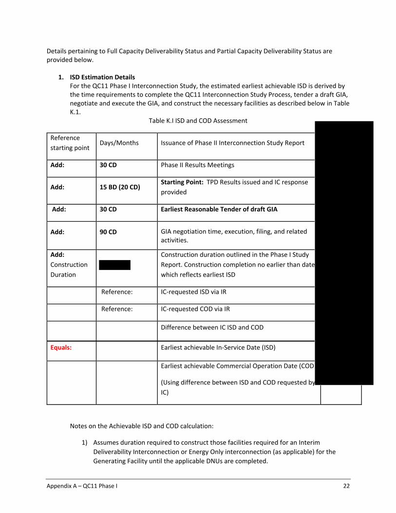
Details pertaining to Full Capacity Deliverability Status and Partial Capacity Deliverability Status are provided below.
1. ISD Estimation Details For the QC11 Phase I Interconnection Study, the estimated earliest achievable ISD is derived by the time requirements to complete the QC11 Interconnection Study Process, tender a draft GIA, negotiate and execute the GIA, and construct the necessary facilities as described below in Table K.1.
Table K.I ISD and COD Assessment
Reference
starting point Days/Months Issuance of Phase II Interconnection Study Report
Add: 30 CD Phase II Results Meetings
Add: 15 BD (20 CD) Starting Point: TPD Results issued and IC response
provided
Add: 30 CD Earliest Reasonable Tender of draft GIA
Add: 90 CD GIA negotiation time, execution, filing, and related activities.
Add:
Construction
Duration
Construction duration outlined in the Phase I Study
Report. Construction completion no earlier than date
which reflects earliest ISD
Reference: IC‐requested ISD via IR
Reference: IC‐requested COD via IR
Difference between IC ISD and COD
Equals: Earliest achievable In‐Service Date (ISD)
Earliest achievable Commercial Operation Date (COD
(Using difference between ISD and COD requested by
IC)
Notes on the Achievable ISD and COD calculation:
1) Assumes duration required to construct those facilities required for an Interim
Deliverability Interconnection or Energy Only interconnection (as applicable) for the
Generating Facility until the applicable DNUs are completed.

Appendix A – QC11 Phase I 23
2) The construction durations shown represent the estimated amount of time needed to
design, procure, and construct the facilities with the start date of the duration based on
the effective date of the GIA; and necessarily include timely receipt of all required
information and written authorizations to proceed (ATP), and timely receipt of
construction payments and financial security postings and other milestones.
3) Assumes that GIA is tendered after the TP Deliverability allocation results are disclosed.
2. ISD Conclusion
SCE can reasonably tender a draft The draft GIA should be executed and/or filed at FERC no later than and will include the earliest ISD and COD as identified in Table K.1. The ISO will perform its Annual Reassessment ( ) and Transmission Plan Deliverability (TPD) Allocation7 (due Any changes in scope, cost, or schedule requirements that come out of ISO’s Annual Reassessment and TPD Allocation will be reflected in a Reassessment Report, which will be used to revise the draft LGIA (if under negotiation) or amend the LGIA (if already executed).
L. ADDITIONAL STUDY ANNOTATIONS 1. Conceptual Plan of Service
The results provided in this study are based on conceptual engineering and a preliminary Plan of Service (POS) and are not sufficient for permitting of facilities. The POS is subject to change as part of detailed engineering and design.
2. The study does not include analysis related to the power output rate of change that may occur due to the following or other conditions:
System morning start up for solar generating facilities: That is when each morning the Generating Facility commences to generate and export electrical energy to the electric system.
Cloud Cover: Solar generating facilities have significant generation output variation (Variability) which can have an impact on electric system voltage profiles.
3. IC’s Technical Data The study accuracy and results for the QC11 Phase I Interconnection Study was contingent upon the accuracy of the IR technical data provided by each IC during the Interconnection Study Cycle. Any changes from the data provided as allowed under GIP should be submitted in the Attachment B within ten (10) Business Days following the Phase I Interconnection Study Results Meeting. Any changes in the Attachment B submission that extended beyond the modifications allowed in accordance with Section 4.5.7.2.2 of GIP would have been evaluated under a Material Modification Assessment (MMA). The MMA process would have determined if such change resulted in a material impact to queued‐behind generation. These change(s) would have been
7 The TPD Allocation Process is estimated to be completed in April 2020. The actual date may vary.
Appendix A – QC11 Phase I 24
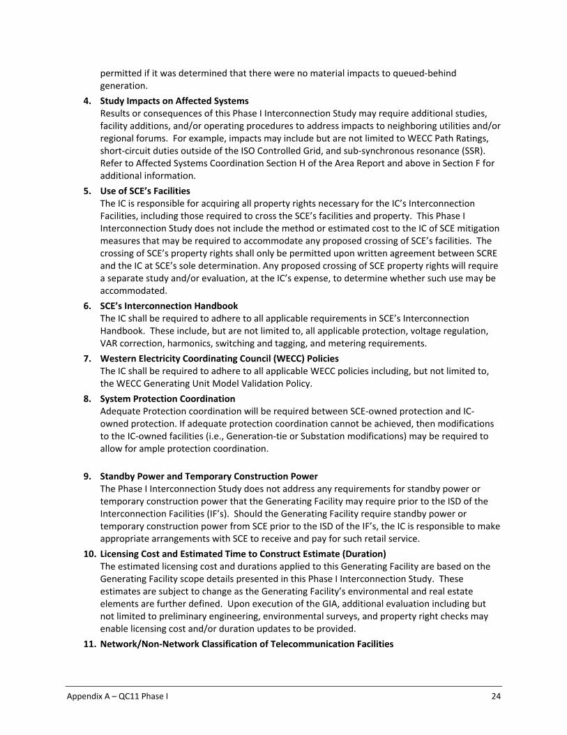
permitted if it was determined that there were no material impacts to queued‐behind generation.
4. Study Impacts on Affected Systems Results or consequences of this Phase I Interconnection Study may require additional studies, facility additions, and/or operating procedures to address impacts to neighboring utilities and/or regional forums. For example, impacts may include but are not limited to WECC Path Ratings, short‐circuit duties outside of the ISO Controlled Grid, and sub‐synchronous resonance (SSR). Refer to Affected Systems Coordination Section H of the Area Report and above in Section F for additional information.
5. Use of SCE’s Facilities The IC is responsible for acquiring all property rights necessary for the IC’s Interconnection Facilities, including those required to cross the SCE’s facilities and property. This Phase I Interconnection Study does not include the method or estimated cost to the IC of SCE mitigation measures that may be required to accommodate any proposed crossing of SCE’s facilities. The crossing of SCE’s property rights shall only be permitted upon written agreement between SCRE and the IC at SCE’s sole determination. Any proposed crossing of SCE property rights will require a separate study and/or evaluation, at the IC’s expense, to determine whether such use may be accommodated.
6. SCE’s Interconnection Handbook The IC shall be required to adhere to all applicable requirements in SCE’s Interconnection Handbook. These include, but are not limited to, all applicable protection, voltage regulation, VAR correction, harmonics, switching and tagging, and metering requirements.
7. Western Electricity Coordinating Council (WECC) Policies The IC shall be required to adhere to all applicable WECC policies including, but not limited to, the WECC Generating Unit Model Validation Policy.
8. System Protection Coordination Adequate Protection coordination will be required between SCE‐owned protection and IC‐owned protection. If adequate protection coordination cannot be achieved, then modifications to the IC‐owned facilities (i.e., Generation‐tie or Substation modifications) may be required to allow for ample protection coordination.
9. Standby Power and Temporary Construction Power The Phase I Interconnection Study does not address any requirements for standby power or temporary construction power that the Generating Facility may require prior to the ISD of the Interconnection Facilities (IF’s). Should the Generating Facility require standby power or temporary construction power from SCE prior to the ISD of the IF’s, the IC is responsible to make appropriate arrangements with SCE to receive and pay for such retail service.
10. Licensing Cost and Estimated Time to Construct Estimate (Duration) The estimated licensing cost and durations applied to this Generating Facility are based on the Generating Facility scope details presented in this Phase I Interconnection Study. These estimates are subject to change as the Generating Facility’s environmental and real estate elements are further defined. Upon execution of the GIA, additional evaluation including but not limited to preliminary engineering, environmental surveys, and property right checks may enable licensing cost and/or duration updates to be provided.
11. Network/Non‐Network Classification of Telecommunication Facilities

Appendix A – QC11 Phase I 25
a. Non‐Network (Interconnection Facilities) Telecommunications Facilities: The cost for telecommunication facilities that were identified as part of the IC’s Interconnection Facilities was based on an assumption that these facilities would be sited, licensed, and constructed by the IC. The IC will own, operate, maintain, and construct main and diverse telecommunication paths associated with the IC’s generation tie line, excluding terminal equipment at both ends. In addition, the telecommunication requirements for the RAS were assumed based on tripping of the generator’s breaker in lieu of tripping the circuit breakers and opening the IC’s gen‐tie at SCE’s substation.
b. Network (Network Upgrades) Telecommunications Upgrades: Due to uncertainties related to telecommunication upgrades for the numerous projects in queues ahead of this Generating Facility, telecommunication upgrades for earlier queued projects without a signed GIA which upgrades have not been constructed were not considered in this study. Depending on the scope of these earlier queued projects, the cost of telecommunication upgrades identified for Phase I may be reduced. Any changes in these assumptions may affect the cost and schedule for the identified telecommunication upgrades.
12. Ground Grid Analysis A detailed ground grid analysis will be required as part of the detailed engineering for the Generating Facility at the SCE substations whose ground grids were flagged with duty concerns.
13. SCE Technical Requirements The IC is advised that there may be technical requirements in addition to those that outlined above in Section C of this report that will be addressed in the Generating Facility GIA.
14. Applicability This document has been prepared to identify the impact(s) of the Generating Facility on the SCE’s electric system; as well as establish the technical requirements to interconnect the Generating Facility to the POI that was evaluated in the final Phase I Interconnection Study for the Generating Facility. Nothing in this report is intended to supersede or establish terms/conditions specified in GIAs agreed to by the SCE, ISO, and the IC.
15. Process for Initial Synchronization Date/Trial Operation Date and COD of the Generating Facility The IC is reminded that the ISO has implemented a New Resource Implementation (NRI) process that ensures that a generation resource meets all requirements before Initial Synchronization Date/Trial Operation Date and COD. The NRI uses a bucket system for deliverables from the IC that are required to be approved by the ISO. The first step of this process is to submit an “ISO Initial Contact Information Request form” at least seven (7) months in advance of the planned Initial Synchronization Date. Subsequently an NRI project number will be assigned to the Generating Facility for all future communications with the ISO. SCE has no involvement in this NRI process except to inform the IC of this process requirement. Further information on the NRI process can be obtained from the ISO Website using the following links: New Resource Implementation webpage: http://www.caiso.com/participate/Pages/NewResourceImplementation/Default.aspx
NRI Checklist: http://www.caiso.com/Documents/NewResourceImplementationChecklist.xls
NRI Guide:

Appendix A – QC11 Phase I 26
http://www.caiso.com/Documents/NewResourceImplementationGuide.doc
16. ISO Market Dispatch This study did not evaluate any potential limitations that may be driven by the ISO market under real‐time operating conditions.
17. Interconnection Request to Third‐Party Owned Facilities Generating Facility’s requesting to interconnect to a Third party owned facility will need to obtain written approval from the owner(s) of the facility prior to execution of the GIA.
18. Future Charging Restrictions Charging restrictions not identified in this study may occur in the future if the underlying operating assumptions prove to be different from the conditions evaluated in this study.

Appendix A – QC11 Phase I 27
Attachment 1: Interconnection Facilities, Network Upgrades, and Distribution Upgrades
Please refer to separate document

Appendix A – QC11 Phase I 28
Attachment 2: Escalated Cost and Time to Construct for Interconnection Facilities, Reliability Network Upgrades,
Delivery Network Upgrades, and Distribution Upgrades Please refer to separate document
Appendix A – QC11 Phase I 29
Attachment 3: Allocation of Network Upgrades for Cost Estimates and Maximum Network
Upgrade Cost Responsibility
Phase I Network Upgrade Cost Allocation
Notes:

Appendix A – QC11 Phase I 30
Attachment 4: SCE’s Interconnection Handbook
Preliminary Protection Requirements for Interconnection Facilities are outlined in SCE’s Interconnection Handbook at the following link:

Appendix A – QC11 Phase I 31
https://www.sce.com/wps/wcm/connect/348e4d71‐5c2a‐431f‐bf78‐
16267486fdc9/Interconnection%2BHandbook_1483725988_1485215238.pdf?MOD=AJPERES

Appendix A – QC11 Phase I 32
Attachment 5: Short‐Circuit Duty Calculation Study Results
Please refer to the Appendix H of the Area Report

Appendix A – QC11 Phase I 33
Attachment 6: IC Provided Generating Facility Dynamic Data
#BLUE SANDS STORAGE #1 54 MW Project #Battery Models models regc_a 698281 "WDT1552_G1" 0.48 "1 " : #9 mvab=30.80 "lvplsw" 1. "rrpwr" 10.0 "brkpt" 0.9 "zerox" 0.4 "lvpl1" 1.22 "vtmax" 1.2 "lvpnt1" 0.8 "lvpnt0" 0.4 "qmin" ‐1.3 "accel" 0.7 "tg" 0.02 "tfltr" 0.02 "iqrmax" 999. "iqrmin" ‐999. "xe" 0 reec_c 698281 "WDT1552_G1" 0.48 "1 " : #9 mvab=0 "vdip" ‐99 "vup" 99 "trv" 0.0 "dbd1" ‐0.05 "dbd2" 0.05 "kqv" 0 "iqh1" 1.05 "iql1" ‐1.05 "vref0" 0 "SOCini" 0.5 "SOCmax" 1 / "SOCmin" 0 "T" 14400 "tp" 0.05 "qmax" 0.62 "qmin" ‐0.62 "vmax" 1.1 "vmin" 0.5 "kqp" 0 "kqi" 0.1 "kvp" 0 "kvi" 120 "tiq" 0.02 "dpmax" 1 "dpmin" ‐1 "pmax" 1 "pmin" ‐1 / "imax" 1.25 "tpord" 0.04 "pfflag" 0 "vflag" 1 "qflag" 1 "pqflag" 1 "vq1" 0 "iq1" 1.45 "vq2" 2 "iq2" 1.45 "vq3" 0 "iq3" 0 "vq4" 0 "iq4" 0 "vp1" 0 "ip1" 1.15 "vp2" 2 "ip2" 1.15 / "vp3" 0 "ip3" 0 "vp4" 0 "ip4" 0 repc_a 698281 "WDT1552_G1" 0.48 "1 " 2 "HV " 69.0 : #9 "mvab" 0. "tfltr" 0.2 "kp" 18. "ki" 5. "tft" 0. "tfv" 0.15 "refflg" 1. "vfrz" ‐1. "rc" 0. "xc" 0. "kc" 0. "vcmpflg" 1. "emax" 999. "emin" ‐999. "dbd" 0. "qmax" 0.44 "qmin" ‐0.44 "kpg" 0.1 "kig" 0.0 "tp" 0.25 "fdbd1" 0. "fdbd2" 0. "femax" 999. "femin" ‐999. "pmax" 999. "pmin" ‐999. "tlag" 0.1 "ddn" 20. "dup" 20.0 "frqflg" 1 "outflag" 0 "puflag" 0 # lhvrt 698281 "WDT1552_G1" 0.48 "1 " 2 "HV " 69.0 : #9 / "vref" 1.00 / "dvtrp1" ‐1.0 "dvtrp2" ‐0.57 "dvtrp3" ‐0.37 "dvtrp4" ‐0.27 "dvtrp5" ‐0.11 / "dvtrp6" 0.24 "dvtrp7" 0.20 "dvtrp8" 0.18 "dvtrp9" 0.11 "dvtrp10" 0.00 / "dttrp1" 0.20 "dttrp2" 0.40 "dttrp3" 2.10 "dttrp4" 3.10 "dttrp5" 100.0 / "dttrp6" 0.25 "dttrp7" 0.60 "dttrp8" 1.10 "dttrp9" 100.0 "dttrp10" 0.00 # lhfrt 698281 "WDT1552_G1" 0.48 "1 " 2 "HV " 69.0 : #9 / "fref" 60.0 / "dftrp1" ‐3.00 "dftrp2" 2.00 "dftrp3" 0.00 "dftrp4" 0.00 "dftrp5" 0.00 / "dftrp6" 0.00 "dftrp7" 0.0 "dftrp8" 0.0 "dftrp9" 0.0 "dftrp10" 0.00 / "dttrp1" 0.20 "dttrp2" 0.20 "dttrp3" 0.00 "dttrp4" 0.00 "dttrp5" 0.00 / "dttrp6" 0.00 "dttrp7" 0.00 "dttrp8" 0.00 "dttrp9" 0.00 "dttrp10" 0.00 # regc_a 698282 "WDT1552_G2" 0.48 "1 " : #9 mvab=30.80 "lvplsw" 1. "rrpwr" 10.0 "brkpt" 0.9 "zerox" 0.4 "lvpl1" 1.22 "vtmax" 1.2 "lvpnt1" 0.8 "lvpnt0" 0.4 "qmin" ‐1.3 "accel" 0.7 "tg" 0.02 "tfltr" 0.02 "iqrmax" 999. "iqrmin" ‐999. "xe" 0 reec_c 698282 "WDT1552_G2" 0.48 "1 " : #9 mvab=0 "vdip" ‐99 "vup" 99 "trv" 0.0 "dbd1" ‐0.05 "dbd2" 0.05 "kqv" 0 "iqh1" 1.05 "iql1" ‐1.05 "vref0" 0 "SOCini" 0.5 "SOCmax" 1 / "SOCmin" 0 "T" 14400 "tp" 0.05 "qmax" 0.62 "qmin" ‐0.62 "vmax" 1.1 "vmin" 0.5 "kqp" 0 "kqi" 0.1 "kvp" 0 "kvi" 120 "tiq" 0.02 "dpmax" 1 "dpmin" ‐1 "pmax" 1 "pmin" ‐1 / "imax" 1.25 "tpord" 0.04 "pfflag" 0 "vflag" 1 "qflag" 1 "pqflag" 1 "vq1" 0 "iq1" 1.45 "vq2" 2 "iq2" 1.45 "vq3" 0 "iq3" 0 "vq4" 0 "iq4" 0 "vp1" 0 "ip1" 1.15 "vp2" 2 "ip2" 1.15 / "vp3" 0 "ip3" 0 "vp4" 0 "ip4" 0 repc_a 698282 "WDT1552_G2" 0.48 "1 " 2 "HV " 69.0 : #9 "mvab" 0. "tfltr" 0.2 "kp" 18. "ki" 5. "tft" 0. "tfv" 0.15 "refflg" 1. "vfrz" ‐1. "rc" 0. "xc" 0. "kc" 0. "vcmpflg" 1. "emax" 999. "emin" ‐999. "dbd" 0. "qmax" 0.44 "qmin" ‐0.44 "kpg" 0.1 "kig" 0.5 "tp" 0.25 "fdbd1" 0. "fdbd2" 0. "femax" 999. "femin" ‐999. "pmax" 999. "pmin" ‐999. "tlag" 0.1 "ddn" 20. "dup" 20.0 "frqflg" 1 "outflag" 0 "puflag" 0 # lhvrt 698282 "WDT1552_G2" 0.48 "1 " 2 "HV " 69.0 : #9 / "vref" 1.00 / "dvtrp1" ‐1.0 "dvtrp2" ‐0.57 "dvtrp3" ‐0.37 "dvtrp4" ‐0.27 "dvtrp5" ‐0.11 / "dvtrp6" 0.24 "dvtrp7" 0.20 "dvtrp8" 0.18 "dvtrp9" 0.11 "dvtrp10" 0.00 / "dttrp1" 0.20 "dttrp2" 0.40 "dttrp3" 2.10 "dttrp4" 3.10 "dttrp5" 100.0 / "dttrp6" 0.25 "dttrp7" 0.60 "dttrp8" 1.10 "dttrp9" 100.0 "dttrp10" 0.00 # lhfrt 698282 "WDT1552_G2" 0.48 "1 " 2 "HV " 69.0 : #9 /

Appendix A – QC11 Phase I 34
"fref" 60.0 / "dftrp1" ‐3.00 "dftrp2" 2.00 "dftrp3" 0.00 "dftrp4" 0.00 "dftrp5" 0.00 / "dftrp6" 0.00 "dftrp7" 0.0 "dftrp8" 0.0 "dftrp9" 0.0 "dftrp10" 0.00 / "dttrp1" 0.20 "dttrp2" 0.20 "dttrp3" 0.00 "dttrp4" 0.00 "dttrp5" 0.00 / "dttrp6" 0.00 "dttrp7" 0.00 "dttrp8" 0.00 "dttrp9" 0.00 "dttrp10" 0.00 # # Infinite bus data gencls 1 "POI" 69.000 "1 " : #5 mva=5000.0000 999999.0000 0.0000 0.0000 1.0000 0.0000 0.0000 0.0000
Appendix A – QC11 Phase I 35
Attachment 7 Subtransmission Assessment Report Please refer to separate document


