Document name WECC Generating Facility Data, … Gen Fac Testing and...Document name WECC Generating...
38
Document name WECC Generating Facility Data, Testing and Model Validation Requirements Category ( ) Regional Reliability Standard ( ) Regional Criteria ( ) Policy (X) Guideline ( ) Report or other ( ) Charter Document date July 13, 2012 Adopted/approved by PCC Date adopted/approved October 10-11, 2012 Custodian (entity responsible for maintenance and upkeep) M&VWG Stored/filed Physical location: Web URL: Previous name/number GTTF_2005- 12_Generating_Facility_Model_Validation_Requirements.doc GTTF 2005-12 Generating Unit Baseline Test Requirements.doc GTTF_2005-12_Generating_Facility_Data_Requirements.doc Over Excitation Limiter and Over Excitation Protection Test Guidelines.doc Generator Test Exemption Guideline.doc Status (X) in effect ( ) usable, minor formatting/editing required ( ) modification needed ( ) superseded by _____________________ ( ) other _____________________________ ( ) obsolete/archived)
-
Upload
phungtuong -
Category
Documents
-
view
221 -
download
3
Transcript of Document name WECC Generating Facility Data, … Gen Fac Testing and...Document name WECC Generating...

Document name WECC Generating Facility Data, Testing and Model Validation Requirements
Category ( ) Regional Reliability Standard ( ) Regional Criteria ( ) Policy (X) Guideline ( ) Report or other ( ) Charter
Document date July 13, 2012 Adopted/approved by PCC Date adopted/approved
October 10-11, 2012
Custodian (entity responsible for maintenance and upkeep)
M&VWG
Stored/filed Physical location: Web URL:
Previous name/number
GTTF_2005- 12_Generating_Facility_Model_Validation_Requirements.doc GTTF 2005-12 Generating Unit Baseline Test Requirements.doc GTTF_2005-12_Generating_Facility_Data_Requirements.doc Over Excitation Limiter and Over Excitation Protection Test Guidelines.doc Generator Test Exemption Guideline.doc
Status (X) in effect ( ) usable, minor formatting/editing required ( ) modification needed ( ) superseded by _____________________ ( ) other _____________________________ ( ) obsolete/archived)

Page 2 of 38
WECC Guideline: Generating Facility Data, Testing and Model Validation Requirements
Date: July 13, 2012 Introduction This guideline provides information regarding facility data needed by transmission planning entities, methods for verifying dynamics data, and validation of dynamics models for generating units and variable generation plants. It was written to provide guidance on data requirements, how to do the baseline tests, and how to perform model validation required by the WECC Generating Unit Model Validation Policy. This document combines and supersedes the previous versions of the following documents:
• WECC Guideline: Generating Facility Model Validation Requirements (10/21/2005)
• WECC Guideline: Generating Unit Baseline Test Requirements (10/21/2005)
• WECC Guideline: Generating Facility Data Requirements (10/21/2005) • Guidelines for Over Excitation System Limiter (OEL) and Over Excitation
Protection (OEP) Testing (2/11/2000) • Procedure for Handling Requests for Exemption Regarding the WECC
Generator Test Policy (4/12/2011) Please reference the following modeling guidelines for more information:
• WECC Wind Power Plant Power Flow Modeling Guidelines (May 2008) • WECC Wind Power Plant Dynamic Modeling Guidelines (November 2010) • WECC Photovoltaic Plant Power Flow Modeling Guidelines (November
2010) • Generic Static Var System Models for WECC (August 2011) • WSCC 1997 Generator Test Request Letter and Guidelines for
Synchronous Unit Dynamic Testing and Model Validation (February 1997) Approved By:
Approving Committee, Entity or Person Date
WECC Modeling and Validation Work Group July 13, 2012
WECC Planning Coordination Committee October 10-11, 2012

Page 3 of 38
Table of Contents Background Appendix A. Generating Facility Model Validation Requirements Appendix B. Generating Unit Baseline Test Requirements Appendix C. Generating Facility Data Requirements Appendix D. Guidelines for Over Excitation System Limiter (OEL) and Over
Excitation Protection (OEP) Testing Appendix E. Procedure for Handling Requests for Exemption Regarding the
WECC Generator Test Policy

Page 4 of 38
Western Electricity Coordinating Council
Background
As described in the March 21, 1997 letter1, the disturbances on July 2 and August 10, 1996 had a considerable impact on the Western Interconnection as well as the electric industry as a whole. Detailed system disturbance reports were prepared following these incidents to comply with WSCC's policies and to address questions raised by The President of the United States, the Department of Energy, and the North American Electric Reliability Council (NERC). Over 140 recommendations were adopted to address specific problem areas identified in the analysis of these events.
The testing of generating units is an extremely important issue which is addressed by the disturbance report recommendations. Therefore, following the disturbances of July 2 and August 10, 1996, the WSCC Control Work Group (CWG) and the Modeling and Validation Work Group (M&VWG) were tasked with developing guidelines for testing generators, excitation systems, power system stabilizers (PSS) and turbine governors for all units greater than 10 MW for verification of reactive limits, proper performance of the dynamic control systems, and validation of the computer models used for stability analysis.
The data obtained from the field testing of the generator exciters, governors and power system stabilizers are to be validated for use in the models of these devices by conducting dynamic simulations of the tests. A good match between the test results and the dynamic simulation of the tests should be established.
It is evident that test guidelines to cover such a wide range of unit types and ratings cannot incorporate in detail what is ideally required for testing each particular unit. Consequently, the enclosed guidelines for dynamic testing are general in scope and content. Typical test methods and guidelines are suggested, but the final selection of the tests to be performed should be made by the test engineer after discussing with the plant test personnel and the analytical modeling engineer the most appropriate tests for the particular type and rating of the unit to be tested.
Since 1997, additional documents have been created to support the ongoing testing and model validation of generators. This document is to consolidate testing requirements to support the WECC Generating Unit Model Validation Policy. The modeling guidelines were intentionally not included in this document, but instead are referenced.
1 The WSCC 1997 Generator Test Request Letter and Guidelines for Synchronous Unit Dynamic Testing and Model Validation can be found posted on the WECC website [www.wecc.biz].

Page 5 of 38
Guidelines and industry experience have been specific to conventional generation with synchronous machines. The installed capacity of variable generation (wind and solar plants) has increased rapidly, and significant growth is expected in the future. However, representation of variable generation in WECC base cases remains problematic due to the lack of suitable models and limited industry experience. To address this gap, the WECC Modeling and Validation Working Group, through the Renewable Energy Modeling Task Force (REMTF), has been developing modeling guidelines and generic models for wind and solar plants. Going forward, the WECC model data and model validation requirements contain specific provisions for application of model data and model validation requirements to variable generation, in accordance to NERC MOD standards.
Page 6 of 38
Western Electricity Coordinating Council Appendix A. Generating Facility Model Validation Requirements Dynamic response validation The essential principle of dynamic response validation is that the model submitted to WECC to represent the generating facility must reproduce the results of tests or reproduce recorded disturbances within reasonable levels of accuracy. This principle must be met by executing simulations of the tests or recorded system events in the PSS/E or PSLF program so as to demonstrate that:
- signals from the tests or recorded events are used as reference data - clearly identifiable variations of input variables are presented to the model
to impose the test or recorded disturbance on the model - the result signals obtained from the simulation are compared to and agree
with the reference data The measure of success of the validation a demonstration of reasonable agreement between the recorded and simulated results. Important characteristics used to determine reasonable agreement include the following:
- general shape of the measured and simulated curves, including magnitude and rate of the response
- rise time, overshoot and bandwidth - dead-bands and delays - initial and final values
Validation results should be discussed in a validation report submitted to WECC. There are several acceptable ways to conduct model validation, as described below.

Page 7 of 38
Option 1. Validation using Recordings taken at the Point of Interconnection of the Generating Facility. Validation is performed using disturbance recordings taken at the Point Of Interconnection (POI) of the Generating Facility (see Figure 1). The dynamic response of the Generating Facility is driven by the voltage and frequency at the POI and the control inputs (e.g. due to voltage and power schedules from the Control Area Operator). During the model validation process, the POI voltage (V), POI frequency (f), and the unit control signals are used as the model inputs. The real power (P) and reactive power (Q) response of the model is compared to the corresponding measured data to determine the model performance. The validation should be done for events of voltage and frequency deviations and oscillations at the point of interconnection. The minimum sampling rate is 20 samples per second. The minimum disturbance record length is 30 seconds.
Figure 1: Validation performed using disturbance recordings taken at the Generating Facility POI
~Unit #1
~Unit #N
P,Q PlantController
PNQN
Power Schedule (AGC) Voltage Schedule
V1refP1ref
VNrefPNref
P1Q1
V1f1
VNfN
Generating Facility
Station Service
PLQL
V, f

Page 8 of 38
Acceptable validation methods for generator excitation or volt/var control models: Event Input to Model Validation Signal (i) Sudden change in voltage at POI due to a grid-side disturbance
- Voltage at POI - Frequency at POI - Control signals
- Power at POI - Reactive power at POI
(ii) Sudden change in Generator reactive power output (greater than 10% of rated MVA) due to a grid-side disturbance or change in voltage reference
- Voltage at POI - Frequency at POI - Control signals
- Power at POI - Reactive power at POI
Acceptable validation methods for governor-turbine models: Event Input to Model Validation Signal (i) Sudden frequency changes (greater than 0.1 Hz) due to a grid-side disturbance or change in load/speed reference
- Frequency at POI - Control signals
- Power at POI
In addition to the data above, the validation exercise should include a reasonable effort to verify reactive power limits, protection settings and other critical model aspects that could not be fully characterized using the disturbance data. This option is appropriate for conventional generators and is best suited for wind and solar plants.

Page 9 of 38
Option 2. Validation using Recordings taken at the Generating Unit. Validation is performed using disturbance and/or test recordings taken at the Generator (see Figure 2). This should be done for every Generator in the Generating Facility. The dynamic response of the Generator is driven by the stator voltage and frequency (or real and reactive load). The response can be also initiated by the control inputs such as voltage reference and speed reference. Validation should be done for the following events: a) disturbances or tests that result in generator stator voltage and reactive power changes. b) disturbances that result in generator frequency changes or tests that result in generator real power changes.
Figure 2: Validation is performed using disturbance and test recordings taken at the Generator
VoltageReferenceReal and
ReactivePower
StatorVoltage andFrequency
~ Exciter
FieldVoltage,FieldCurrent
VoltageRegulator
PSS
Limiters:OEL, MEL
Turbine
Governor
Control Valveor Gate Opening Speed
Reference
Page 10 of 38
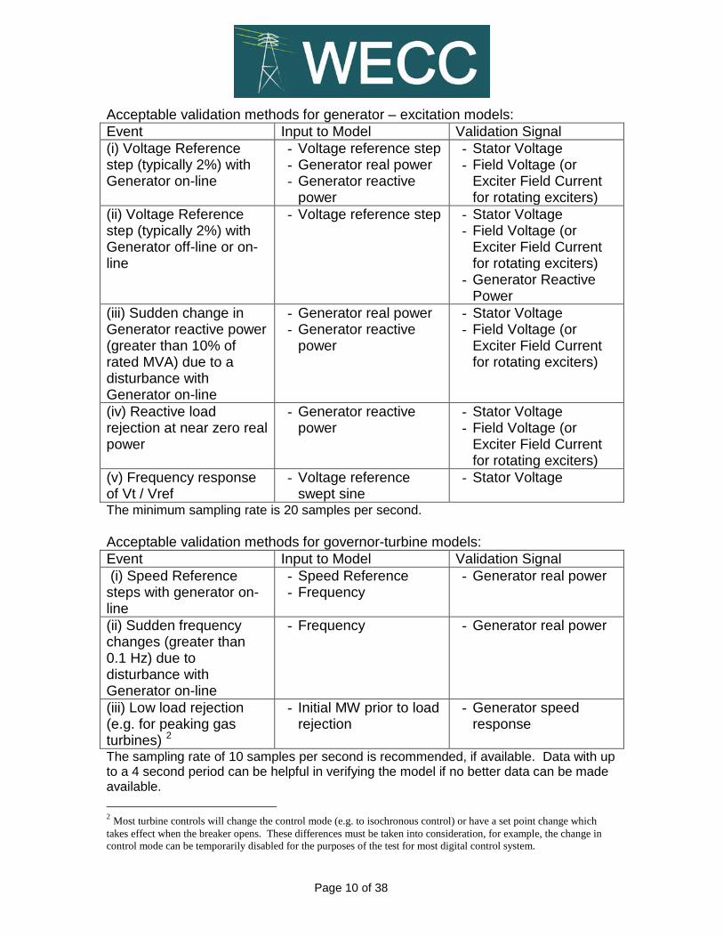
Acceptable validation methods for generator – excitation models: Event Input to Model Validation Signal (i) Voltage Reference step (typically 2%) with Generator on-line
- Voltage reference step - Generator real power - Generator reactive
power
- Stator Voltage - Field Voltage (or
Exciter Field Current for rotating exciters)
(ii) Voltage Reference step (typically 2%) with Generator off-line or on-line
- Voltage reference step
- Stator Voltage - Field Voltage (or
Exciter Field Current for rotating exciters)
- Generator Reactive Power
(iii) Sudden change in Generator reactive power (greater than 10% of rated MVA) due to a disturbance with Generator on-line
- Generator real power - Generator reactive
power
- Stator Voltage - Field Voltage (or
Exciter Field Current for rotating exciters)
(iv) Reactive load rejection at near zero real power
- Generator reactive power
- Stator Voltage - Field Voltage (or
Exciter Field Current for rotating exciters)
(v) Frequency response of Vt / Vref
- Voltage reference swept sine
- Stator Voltage
The minimum sampling rate is 20 samples per second. Acceptable validation methods for governor-turbine models: Event Input to Model Validation Signal (i) Speed Reference steps with generator on-line
- Speed Reference - Frequency
- Generator real power
(ii) Sudden frequency changes (greater than 0.1 Hz) due to disturbance with Generator on-line
- Frequency - Generator real power
(iii) Low load rejection (e.g. for peaking gas turbines) 2
- Initial MW prior to load rejection
- Generator speed response
The sampling rate of 10 samples per second is recommended, if available. Data with up to a 4 second period can be helpful in verifying the model if no better data can be made available. 2 Most turbine controls will change the control mode (e.g. to isochronous control) or have a set point change which takes effect when the breaker opens. These differences must be taken into consideration, for example, the change in control mode can be temporarily disabled for the purposes of the test for most digital control system.

Page 11 of 38
Validation examples are described in the following IEEE papers:
1) “Guidelines for Generator Stability Model Validation Testing”, The Power Engineering Society General Meeting, June 2007, pp. 1-16.
2) Les Pereira, John Undrill, Dmitry Kosterev, Donald Davies and Shawn
Patterson, “A New Thermal Governor Modeling in WECC,” IEEE Transactions on Power Systems, vol.18, no.2, pp.819-829, May 2003.
3) Les Pereira, Dmitry Kosterev, Donald Davies and Shawn Patterson, “New
Thermal Governor Model Selection and Validation in the WECC,” IEEE Transactions on Power Systems, vol.19, no.1, pp.517-523, February 2004.
4) Dmitry Kosterev, “Hydro Turbine-Governor Model Validation in Pacific
Northwest,” IEEE Transactions on Power Systems, vol.19, no.2, pp.1144-1149, May 2004.

Page 12 of 38
Western Electricity Coordinating Council Appendix B. Generating Unit Baseline Test Requirements A great amount of technical information on methods of synchronous generator testing is provided in WSCC 1997 Generator Test Request Letter and Guidelines posted on the WECC website [www.wecc.biz]. 1. Synchronous Generators The following tests should be done:
a. Open Circuit Saturation. Measurement of the steady state variation of generator field current versus generator stator voltage from the minimum achievable generator stator voltage to at least 105 percent of the rated stator voltage with the generator circuit breaker open. For machines with brushless exciters the field current measurement should be the field current of the exciter.
b. Inertia. A test that reasonably confirms the inertia constant of the turbine-generator.
For example, recording of the rotor speed following opening of the generator circuit breaker with the generator running at a moderate real power output.
c. Synchronous Machine Impedances and Time Constants. Tests that reasonably confirm the d-axis reactances (Xd, X’d, X”d) and time constants (T’do and T”do) of the synchronous generator.
For example, recording of terminal voltage and field current following opening of the generator circuit breaker with the generator running at near-zero real power and under-excited so as to absorb substantial reactive power with the excitation system in manual field voltage control.
d. V-curve data. Measurements of steady state real and reactive power, terminal voltage, field current and field voltage at various load points (as low and high real power as possible with multiple reactive power levels that are monotonically taken) at both leading and lagging power factors to provide a basis for the estimation of the steady state reactances and saturation characteristics (Xd, Xq, Kis) of the synchronous generator under loaded conditions. For machines with brushless exciters the field current measurement should be the field current of the exciter.

Page 13 of 38
2. Excitation Systems Tests of the excitation system should be such that they reasonably confirm the characteristics of the voltage regulator and the exciter from dc to 5 Hz. The test recordings should include generator terminal voltage, field voltage or exciter field current for brushless excitation systems. These tests should be done with the excitation system in automatic voltage control. One or more of the following tests can meet the above requirement:
a. VAR Rejection Test. Recording of stator voltage, field voltage (exciter field current for brushless exciters) following opening of the generator circuit breaker with the generator running at near-zero real power and under-excited so as to absorb substantial reactive power.
b. Open Circuit Voltage Reference Step. Recording of stator voltage, field voltage (exciter field current for brushless exciters) following a clearly identifiable step change of voltage regulator reference with the generator circuit breaker open.
c. On-Line Voltage Reference Step. Recording of stator voltage, field voltage (exciter field current for brushless exciters) following a clearly identifiable step change of voltage regulator reference with the generator circuit breaker closed and the generator at normal real power output.
d. Open Circuit Frequency Response Test. Gain and phase angle measurement of stator voltage / voltage reference using a swept sign input from 0.05 Hz to 10 Hz.
3. Power System Stabilizer (PSS) Tests of the PSS should be such that they identify the PSS transfer function up to 10 Hz. Approaches for PSS testing are described in WECC Power System Stabilizer Tuning Guidelines and WECC Power System Stabilizer Design and Performance Criteria. 4. Over-Excitation Limiter (OEL) Update OEL model data as necessary. Approaches for OEL testing are described in Guidelines for Over-Excitation Limiter (OEL) and Over-Excitation Protection (OEP) Testing.

Page 14 of 38
5. Turbine Control
a. Hydro Unit Tests of the governor and turbine should be such that they reasonably confirm the characteristics from dc to 1 Hz. The following test is acceptable: On-Line Speed Reference Step: Recording of generator speed, generator speed reference, gate (valve) position, blade angle if applicable, and generator power following a clearly identifiable step change in speed reference with the generator circuit breaker closed and the generator at normal real power output. The following measurements should also be made: i. Measurement of turbine-governor steady-state droop. ii. Measurement of steady-state generator power versus gate position (and
blade angle versus gate position for Kaplan turbines) at typical operating heads.
b. Steam Turbine Units and Gas Turbine Units The turbine-governor model should be representative of the actual behavior of the unit the majority of the time. Provide recordings of generator power (resolution of 0.5% or better and 4 second sampling time or shorter; sampling rate of 10 samples per second is recommended, if available) for events including frequency deviations. Sources of the data include, but not limited to, plant DCS, SCADA, digital event recorders. Simulated behavior should reasonably match the recorded data. The methodology for thermal governor response validation is described in IEEE papers prepared by the members of WECC Governor Modeling Task Force: 1) Les Pereira, John Undrill, Dmitry Kosterev, Donald Davies and Shawn
Patterson, “A New Thermal Governor Modeling in WECC,” IEEE Transactions on Power Systems, vol.18, no.2, pp.819-829, May 2003.
2) Les Pereira, Dmitry Kosterev, Donald Davies and Shawn Patterson, “New Thermal Governor Model Selection and Validation in the WECC,” IEEE Transactions on Power Systems, vol.19, no.1, pp.517-523, February 2004.

Page 15 of 38
6. Variable Generation Plants The methodology for validation of wind and solar power plant models is similar to that of conventional generators. Some differentiation is needed to account for the nature of PV and wind plants. Wind and solar generating plants consist of a large number of wind turbine-generator (WTG) units or PV inverters with local controls that respond dynamically to system disturbances. Large plants commonly have a slower plant-level supervisory control that coordinates the response of WTGs/inverters based on control objectives at the POI. The plant controller may also coordinate the operation of reactive support devices that may be present within the plant. The following baseline testing guidelines are applicable to variable generation plants.
a. Baseline type validation of WTGs and PV inverters models It is not necessary (nor practical) to test every WTG or PV inverter installed in the plant to conduct a baseline model validation. Type testing is acceptable. A type test is a test conducted on the make and model of WTG or PV inverter installed in a plant. Baseline validation of the model provided to WECC (WECC model) should be against Reference Data, which can be factory tests, field tests, field disturbances, or simulated response obtained from manufacturer-validated reference models. The validation should be with respect to active and reactive power injection at the machine terminals, with emphasis on steady-state levels pre and post event, as well as post-event recovery dynamics. • Machine dynamic response to a fault or voltage dip event. The
baseline type validation for WTGs and PV inverters should demonstrate a reasonable match of the WECC model against Reference Data for a fault or voltage dip event that results in residual voltage of 60% or lower at the high-side of the step-up transformer of the WTG or inverter.
• Machine dynamic response to a frequency event. The baseline type validation should demonstrate a reasonable match of the WECC model with respect to a frequency event.
The tests described above should be relevant with respect to control settings and capabilities deployed in the plant of interest. Evidence of validation should be provided for output level of partial (40-60%) and near full (75-100%) of MW rating.

Page 16 of 38
b. Plant-level baseline test
Baseline tests should be conducted to reasonably confirm the effect of plant controls. The validation should be with respect to active and reactive power injection at the Point of Interconnection, with emphasis on pre and post event levels, and recovery dynamics. The test can involve a change in control set points, such as a change of volt/var reference, or capacitor/reactor switching. At a minimum, the validation should be demonstrated for the following output ranges (1) 40% to 60% of rated output and (2) 75% to 100% of rated output. • Plant volt/var response to a system event. The baseline validation
should demonstrate a reasonable match between the WECC approved model and measured data with respect to reactive power response. For the purposes of this baseline test, the dynamic response should involve a voltage change of typically 2% or a reactive power change of at least 10% rated MVA.
• Plant steady-state reactive output and control capability. The baseline
validation should demonstrate reasonable match with respect to steady-state reactive power injection between the equivalent model provided to WECC and measured data at the Point of Interconnection.
• Plant dynamic response to a frequency event. The baseline validation
should demonstrate a reasonable match of the WECC plant controller model with respect to a frequency event. Only an over-frequency response would typically be expected for wind and PV plants.
• Model validation against measured data is also acceptable, provided
that the disturbance is sufficiently large to validate the model.

Page 17 of 38
Western Electricity Coordinating Council Appendix C. Generating Facility Data Requirements
The following table summarizes the sections in this Appendix that apply to synchronous and/or non-synchronous generating facilities. Section Synchronous Non-Synch 1 Principal one-line electrical diagram of the generating facility x x 2 Generator Data x x 2.1 Synchronous Generator Data x 2.2 Non-Synchronous Generator Data x
2.3 Generator Excitation System or Reactive Power Control Data x x
2.3.1 Synchronous Exciter and Voltage Regulator x 2.3.2 Non-Synchronous Generator Reactive Power Control Data x 2.3.3 Line Drop Compensation/Reactive Current Compensation x x 2.3.4 Power System Stabilizer x 2.3.5 Over-Excitation Limiter (OEL) x x 2.3.6 Under-Excitation Limiter (UEL) x x 2.3.7 Stator Current Limiter x
2.3.8 High Voltage Bus Controllers, VAR limiters and Power factor controllers x x
2.4 Synchronous Generator Reactive Capability and ‘V’ Curves x 2.5 Non-Synchronous Generator Reactive Capability Curves x 3 Turbine-Governor (or Frequency Control) Data x x 3.1 Hydro-Turbine Generators x 3.2 Steam-Turbine x 3.3 Gas Turbines x 3.4 For Combined Cycle Plants x 3.5 Wind Turbines x 3.6 Photovoltaic Generators x 3.7 Generators without WECC-approved models x x 4 Power Plant Controls x x 4.1 Load or MW controller x x 4.2 Reactive Power Controller x x 5 Transformers x x 5.1 Transformer Data x x 5.2 Transformer(s) between Collector and Generator x 6 Line Data x x 6.1 Transmission Line Data x x 6.2 Collector System Equivalence x 7 Auxiliary Load x x

Page 18 of 38
Submit the facility data, ascii dynamic data file (GE PSLF dyd), and a copy of the test report to [email protected]. Provide contact name and information for generator owner, transmission planner, and test report submitter. 1. Principal one-line electrical diagram of the generating facility Provide a principal one-line diagram of the generating facility with adequate representation for power flow modeling of the plant. The one-line diagram should identify generating units, transformers (main step-up, unit auxiliaries, excitation source), transmission lines associated with the generation facility, station service loads, and any other relevant electrical equipment (e.g. capacitors, static var compensators). For variable generation plants, provide the equivalent one-line diagram consistent with the wind and solar powerflow modeling guide. 2. Generating Unit Data
Label the generating unit number or identifier in the plant diagram.
2.1. Synchronous Generator Data • Provide synchronous generator nameplate data, including rated MVA,
kV, stator Amps, power factor, RPM, exciter voltage, rotor Amps. • Provide a completed data form for the corresponding WECC-approved
model (document “WECC Approved Models”), which includes but not limited to the following generator parameters:
Impedance Data in per unit on machine rated MVA and kV Synchronous direct axis reactance – unsaturated Xdi Synchronous quadrature axis reactance– unsaturated Xqi Transient direct axis reactance – unsaturated X’di Transient quadrature axis reactance – unsaturated (*) X’qi Subtransient direct axis reactance – unsaturated X”di Subtransient quadrature axis reactance – unsaturated (*) X”qi Leakage reactance Xl Positive sequence resistance Ra
Field Time Constants Open circuit transient time constant – direct axis T’do Open circuit transient time constant – quadrature axis (*) T’qo Open circuit subtransient time constant – direct axis T”do Open circuit subtransient time constant– quadrature axis T”qo
Combined Turbine-Generator(-Exciter) Inertia Inertia Constant H
Open-Circuit Saturation Saturation at 1.0 pu generator voltage S1.0 Saturation at 1.2 pu generator voltage S1.2 (*) not required for salient pole generators

Page 19 of 38
• Provide generator open circuit saturation curve with air-gap line. • Air gap field current at rated generator voltage _______________ Amps • Measured field winding resistance _________ Ohms • Field winding temperature or generator hot air/gas temperature at which
the field winding resistance was measured _________ ºC
2.2. Non-Synchronous Generator Data (e.g. Wind, Photovoltaic) • Provide generator type and manufacturer. • Provide generator nameplate data, including rated MVA, kV, power
factor. • Provide generator plant equivalent model (see power flow modeling
guidelines). • Provide a completed data form for the corresponding WECC-approved
model (document “WECC Approved Models”).
2.3. Generator Excitation System or Reactive Power Control Data
2.3.1 Synchronous Exciter and Voltage Regulator • Excitation system type (static, ac rotating, brushless, dc generator,
etc) and manufacturer. • Provide nameplate information on excitation equipment (such as
excitation transformer in static exciters, dc generator and amplidyne in dc rotating exciters, main and pilot ac generators in ac rotating exciters).
• Voltage regulator type and manufacturer (e.g., GE EX 2100, ABB Unitrol-F, etc).
• Provide a completed data form for the corresponding WECC-approved model (document “WECC Approved Models”).
2.3.2 Non-Synchronous Generator Reactive Power Control Data (e.g.
Wind, Photovoltaic) • Provide a completed data form for the corresponding WECC-
approved model (document “WECC Approved Models”).
2.3.3 Line Drop Compensation/Reactive Current Compensation • Indicate whether the voltage regulator has a line drop compensation
or reactive current compensation, and provide settings in per unit on machine rated MVA and kV.
Page 20 of 38
2.3.4 Power System Stabilizer (Synchronous only) • PSS type and manufacturer (e.g., GE EX2000, Basler) • Provide a completed data form for the corresponding WECC-
approved model (document “WECC Approved Models”).
2.3.5 Over-Excitation Limiter (OEL) • Indicate OEL type and manufacturer. • Describe OEL time characteristic (definite time, inverse time). • Provide pickup vs. time characteristic curve. • Describe OEL actions (e.g., reduce field current below continuous
current rating, trip voltage regulator into manual field current control, trip the generator.)
• Provide a completed data form for the corresponding WECC-approved model (document “WECC Approved Models”).
2.3.6 Under-Excitation Limiter (UEL)
• Provide fullest available information on UEL. • UEL type (conventional or voltage sensitive, PQ-limiter, etc). • Describe UEL actions. • Provide limit settings as a curve of real and reactive power.
2.3.7 Stator Current Limiter (Synchronous only) • Is a stator current limiter incorporated into the excitation system? • Provide fullest available information on stator current limiter.
2.3.8 High Voltage Bus Controllers, VAR limiters and Power factor controllers • Provide fullest available information on these controllers. • Indicate which of these controllers are active in normal operation.
2.4. Synchronous Generator Reactive Capability and ‘V’ Curves • Continuous field current rating ____________ Amps • For hydrogen-cooled generators, indicate hydrogen pressure during
normal operating conditions ______ psi. • Provide machine reactive capability curves at rated voltage and nominal
hydrogen pressure). • Superimpose generator control, limiter and protection curves on the
machine reactive capability curve.

Page 21 of 38
• Define the operating reactive capability of the generator. • Provide information on reactive power limits implemented by plant or unit
supervisory controls (e.g. plant DCS, GE Mark V/ Mark VI / Ovation, GDACS).
2.5. Non-Synchronous Generator Reactive Capability Curves (e.g. Wind, Photovoltaic) • Provide machine reactive capability curves. • Define the operating reactive capability of the generator equivalent. • Provide information on reactive power limits implemented by plant or
unit supervisory controls.
3. Turbine-Governor (or Frequency Control) Data
3.1. Hydro-Turbine Generators • Turbine type (e.g., Francis, Kaplan, Pelton). • Nominal head _______ ft • Typical range of operating heads ______ ft. • Turbine capacity at full gate opening, nominal head ___________ MW. • Turbine capacity at full gate opening, minimum head ___________ MW. • Turbine capacity at full gate opening, maximum head ___________ MW. • Provide the “Power versus Gate Position” characteristic at expected
operating heads (for Kaplan turbines with blade on the cam). For Kaplan turbines, provide the “Blade angle versus Gate Position” characteristic at expected operating heads.
• Provide contact information for a person for reference regarding hydraulic profile of the plant.
• Water inertia starting time Tw __________ sec. • Hydro governor type (e.g. Asea analog electronic, Woodward dash-pot,
Woodward 505H, Voest Alpine electronic). • Provide a completed data form for the corresponding WECC-approved
models (document “WECC Approved Models”). • For Kaplan turbines, provide block diagram with relevant data for a blade
controller.
3.2. Steam-Turbine • Boiler type (drum-type or once through) ___________________ • Normal fuel type (coal, oil, gas, other) _____________________

Page 22 of 38
• Indicate whether the turbine is tandem-compound or cross-compound. • Turbine capacity at rated steam throttle pressure, full valve opening
____________ MW • Rated steam pressure (HP) ____________________ psi • Governor type and manufacturer • Boiler controller type and manufacturer • Describe the normal turbine control and operating practice (base loaded,
turbine follow, boiler follow, coordinated controller, sliding pressure, etc).
• Provide a completed data form for the corresponding WECC-approved models (document “WECC Approved Models”).
3.3. Gas Turbines
• Gas turbine type and manufacturer (e.g. GE Frame 7, W-501, GE LM6000, etc)
• Provide the maximum turbine output as a function of ambient temperature.
3.4. For Combined Cycle Plants
• If the plant has a steam cycle, describe how steam is used from a heat recovery steam generator (HRSG), e.g. - all steam is used by a steam-turbine generator, or - 40% of steam is for industrial use, or - the project is using supplementary duct firing, all steam is used by a
steam-turbine generator • Provide a completed data form for the WECC-approved models
(document “WECC Approved Models.”).
3.5. Wind Turbines • Provide a completed data form for the corresponding WECC-approved
model (document “WECC Approved Models”).
3.6. Photovoltaic Generators • Provide a completed data form for the corresponding WECC-approved
model (document “WECC Approved Models”). 3.7. Generators without WECC-approved models
• Provide a description of the operational characteristics.

Page 23 of 38
4. Power Plant Controls
4.1. Load or MW controller • Indicate whether the plant has an active load controller (e.g. Process
Coordinated Controller). • Describe load controller functions:
- Does it keep the MW output of the plant at a specified set-point? - Does it have a frequency bias and dead-band?
• Provide recordings of plant response to system frequency excursions, if available.
• Provide information on AGC capability, maximum ramp rates (up and down), and ranges (low and high). Provide ramp rate recordings, if available.
4.2. Reactive Power Controller
• Indicate whether the plant has any reactive power controller (high-side voltage controller, reactive power balancing among units, etc).
• Describe the reactive power controller functions: - Does the controller balance reactive power among generators in the
plant? - Does the controller perform high-side voltage control automatically
and how fast it starts and completes response? - Does the controller limit generator terminal voltage (e.g. +/- 5% of
nominal)? - Shunt devices with automatic control schemes. Provide pickup level
and time delays. • Provide SCADA recordings of plant response to system voltage
deviations, if available, showing the effect of the plant reactive power controller.
5. Transformers
5.1. Transformer Data • Provide the following information for each of the transformers identified
in the principal one-line diagram of the generating facility, and provide a picture of each nameplate.
• Application (GSU/CSU/LT): _________________ • Transformer Type (three 1-phase or one 3-phase): ________________ • Number of Windings (2 or 3): ________________ • Indicate whether the unit is an autotransformer: __________

Page 24 of 38
Note: Subsequent data in rows identified with asterisk (*) are required only for 3-winding transformers.
Winding Data:
Winding Nominal Configuration Transformer Type
Nameplate MVA Ratings (for single-phase, provide individual
transformer rating)
[kV] [Δ, Y, Ygrd ] Single or 3-
phase Above each column also indicate cooling
type (e.g. OA, FA, FO, FOA, ONAN)
Primary – H
Secondary – X (*) Tertiary or (Secondary2) – Y
Impedance Data (base MVA= ______, base kV= _____ ): Windings R1 X1 R0 X0
H to X
(*) H to Y
(*) X to Y
No-Load Taps (put "X" in the "Operating Tap" column next to the operating tap):
Primary - H Operating Tap
Primary – H in kV
Secondary - X Operating Tap
Secondary – X in kV
Secondary – Y Operating Tap
Secondary – Y in kV
1 2 3 4 5
Load-Tap Changer:
Tap Changer winding
(H, X, or Y)
Tap Range [kV or Percent]
Taps Down Taps Up
Step size No. of Steps Step size No. of Steps
For on-load tap changers, specify the following: • Regulated voltage: ____________ percent, or Volts • Controlled bus: ____________ • Dead-band: ____________ percent, or Volts • Tap changer time constant: _____________ sec

Page 25 of 38
5.2. Transformer(s) between Collector and Generator (e.g. Wind,
Photovoltaic) • Provide the following information for the transformer(s) identified in the
principal one-line diagram of the generating facility between the collector system and the generators, and that are being reduced to an equivalent transformer, and provide a picture of the nameplate for one of each unique transformer.
Winding Data: Winding Nominal Configuration Nameplate MVA Ratings
[kV] [Δ, Y, Ygrd ] Above each column also indicate cooling
type (e.g. OA, FA, FO, FOA)
Primary – H
Secondary – X Impedance Data (base MVA= _________, base kV= __________): Windings R1 X1 R0 X0
H to X
• Provide the equivalent transformer data of the generating facility between the collector system and the generators.
• Number of transformers in the equivalence: ________________
Equivalent Transformer Winding Data: Winding Nominal Configuration Nameplate MVA Ratings
[kV] [Δ, Y, Ygrd ] Above each column also indicate cooling
type (e.g. OA, FA, FO, FOA)
Primary – H
Secondary – X Equivalent Transformer Impedance Data (base MVA= _________, base kV= __________): Windings R1 X1 R0 X0
H to X

Page 26 of 38
6. Line Data
6.1. Transmission Line Data Provide the following data for each of the transmission lines identified in the principal one-line diagram of the generating facility: Nominal operating voltage, kV Line length, mi Positive sequence line resistance, pu Positive sequence line reactance, pu Positive sequence line susceptance, pu MVA Base for pu values kV Base for pu values
Please indicate whether the line is overhead or underground.
6.2. Collector System Equivalence (e.g. Wind, Photovoltaic) Provide the following data for each of the collector system equivalent circuits identified in the principal one-line diagram of the generating facility: Nominal operating voltage, kV Percent of line Overhead, % Percent of line Underground, % Equivalent Positive sequence line resistance, pu Equivalent Positive sequence line reactance, pu Positive sequence line susceptance, pu MVA Base for pu values kV Base for pu values
7. Auxiliary Load • Provide auxiliary load MW and MVAR at minimum stable and maximum
power output. • Auxiliary load may be identified as any load at utilization voltage less than
the transmission system interconnection voltage, including station service load and unit service load.
• Provide a description of where the loads are connected to the system.

Page 27 of 38
Western Electricity Coordinating Council Appendix D. Guidelines for Over Excitation System Limiter (OEL) and Over Excitation Protection (OEP) Testing Introduction This guideline provides detailed information regarding the data necessary for modeling overexcitation limiters in stability programs and test methods. The purpose of the Overexcitation Limiter (OEL) is to insure that the thermal capability of the field winding is not exceeded while the automatic voltage regulator is in control. It is important to distinguish between an Overexcitation Limiter and an Overexcitation Protection Device (OEP). While an OEL acts through the voltage regulator to reduce and maintain field current within the capability of the field winding, an OEP serves to remove the voltage regulator from service or trip the generator off line. Data submitted for these devices (OEL or OEP) should include the following:
1. Minimum Pickup Value in per unit. This is the minimum value of field current for which the device will operate (begin timing).
2. Maximum Field Current Limit in per unit (if applicable). This is the maximum field current allowable by the device. This is an instantaneous limit or trip.
3. Timed Field Current Limit in per unit. This is the field current level after the limiter has taken control or transferred to manual control.
4. Time Delay between pickup and limit or trip in seconds for at least 3 different current levels. For a fixed time delay (no inverse-time characteristic), only one value is necessary.
5. Whether or not the voltage regulator remains in service, control is transferred to manual, or the unit is tripped when the device operates.
Test Methods: Test methods are briefly described below. More details and sample test guidelines, OEL model description and the Per Unit System Description can be found in the program manuals..
• Limits and trips related to overexcited operation should be field checked by tests in which changes are applied to the voltage regulator to drive it to a high or low output within prudence. The high or low output should be allowed to remain in effect until corrected by limiters or trips.

Page 28 of 38
• The pickup levels, time delays, and levels at which the limiters or trips operate should be recorded.
• Limiter and/or trip settings may need to be temporarily changed during testing in order to avoid excessive currents and or voltages.
• Alternatively, limiter or trips can be calibrated while the unit is shut down using conventional relay test techniques. This method is likely to be the preferred method for steam units, since any testing of this sort carries with it the possibility of an unexpected unit trip. However, where practical, limits and trip settings should be determined by challenging the limits in loaded operation. Where appropriate, the limiter and trip elements can be described by graphs and/or tables.
Example Test Methods: More details and sample test guidelines are included in the following.

Page 29 of 38
Example Test Guidelines for Overexcitation Limiters (OEL) and Overexcitation Protection Devices (OEP)
Introduction The purpose of the Overexcitation Limiter (OEL) is to insure that the thermal capability of the field circuit is not exceeded while the automatic voltage regulator is in control. The ANSI C 50.13 field winding short time thermal capability curve should be used as the guideline for protecting the machine field winding. Although it is noted that this standard addresses only round rotor machines, it is to be assumed that it applies also to salient pole machines, since currently there is no standard that specifically addresses them. Other portions of the field circuit, such as thyristor bridges, also have a thermal capability limit (current rating) and need to be considered when applying overexcitation limiters and protection. It is important to distinguish between an Overexcitation Limiter and an Overexcitation Protection Device (OEP). While an OEL acts through the voltage regulator to reduce and maintain field current within the capability of the field winding, an OEP serves to remove the voltage regulator from service or trip the generator off line. When employed with an OEL, the OEP serves as a backup to the OEL, and should be set to coordinate with the OEL and the ANSI capability curve. For the purpose of computer modeling, it is necessary to model the first line of defense only. In the case where both an OEL and an OEP are present, this means that only the OEL is modeled. However, to insure that the OEL and OEP characteristics coordinate properly (i.e., do not cross each other), it is desirable that each device be tested. This will guarantee that there are no operating points that would result in the unit tripping rather than limiting field current. Older systems may not have an OEL or OEP, while most modern systems offer both at least as an option. There are numerous variations on the design of OEL and OEP devices, but they all operate upon the same principles: Monitor the machine excitation level (field current or perhaps field voltage), allow the excitation to be raised above a determined level (the continuous field current rating) for a short period of time, and reduce or remove excitation after the time period is exceeded. This allows a machine to support a stressed power system as much as possible without incurring thermal damage to its field circuit or stator core. Since the capability of the field winding and other elements of the field circuit are of a thermal nature, as illustrated by the referenced ANSI curve, most modern OEL and OEP devices have an inverse time functionality, along with an instantaneous unit which sets the maximum allowable field current. However, there are also simpler devices, which operate after a fixed time delay when the minimum pickup value is exceeded.

Page 30 of 38
There is also some variation among limiters with respect to how the output signal is used. The limiter output signal may be used to lower the reference of the voltage regulator, or it may be a take-over limiter, which bypasses the voltage regulator and directly controls the level of excitation. In order to determine the structure of the OEL and identify any filtering and gain stages and variable parameters, it is advantageous to have access to the circuit diagrams in the manufacturer's operation manual. The input signal used for the OEL and OEP circuits is usually the output of an isolated field current transducer, which provides a small dc signal representing field current. In some cases, field voltage is the quantity represented by the input signal. If the input signal is derived from field voltage, the results of the test will be dependent upon the temperature of the field winding, since the field resistance, and therefore the field voltage vary with temperature. It is therefore important in this case to maintain a constant field temperature while conducting the tests. The characteristics of the OEL and OEP will become slightly more conservative as the field temperature increases. Since there are so many different variations of overexcitation devices, it is not possible to develop a detailed test procedure that will be appropriate for all systems. Therefore, the simplest and most reliable approach to testing these devices is by challenging the devices while in service with their normal settings. This method is preferred since it not only ensures that the devices function properly, but that the machine responds as desired and there are no coordination conflicts with other devices, such as a field overvoltage or overcurrent relay. In most cases, performing an on-line, functional test of the OEL will not be practical, and testing will have to be performed by temporarily lowering the settings, or while the unit is shut down. The preferred test method will be described first, followed by alternate methods. It is recognized that the first method will generally only be appropriate for units that share a common bus with another unit that can help buffer the resulting voltage changes (hydro units), while other units will probably require an alternate method. The following test guidelines are general enough to be applicable to most system designs for any vintage of excitation system. Digital control equipment is likely to lend itself to monitoring and setting the necessary machine and controller quantities and result in a simpler, more streamlined effort than for older systems.
A. Testing under loaded, overexcited conditions (Typically Hydro Units Only) It is first necessary to establish the value for rated field current. This is the field current required to obtain the full load, rated megawatts at the rated power factor.

Page 31 of 38
Alternately, this may be the maximum continuous field current allowed due to an operating restriction. Testing of the devices will require the unit to be forced into an overexcited condition. The quicker the field current is raised to the test value, the more accurate the timing data. Therefore, it is preferable to make a step change in the voltage regulator reference. This can be accomplished by connecting a power supply through a switch into the summing junction of the voltage regulator. Some systems include a spare input for this purpose. It will be necessary to examine the voltage regulator circuit schematic to determine the location to insert the signal, and the magnitude of the input required. Digital systems may include a provision for entering the change in the voltage reference via the software interface. Alternately, a step input may be achieved by making an unbalanced transfer from manual field control to voltage regulator control, with the voltage regulator reference adjusted to produce the desired test excitation level. A third, less exact, alternative is to raise excitation through normal means using the voltage adjust control. This method should only be used if both of the first two methods are impractical.
To perform a test of an OEL 1. Load the machine to at least 80 percent rated load. At all times during the
testing, monitor the stator current and terminal voltage. If it is apparent that the test cannot be conducted without exceeding prudent levels of terminal voltage or stator current, another method of testing should be substituted.
2. Increase excitation until rated field current is reached. Make sure that the
OEL has not picked up. Measure or note the input signal into the limiter circuit. This will be a signal representing field current or field voltage. Record this value.
3. Slowly increase excitation to determine the minimum level of field current at
which the limiter picks up and begins timing. A typical level of pickup is around 105 percent of rated field current. Some systems have some sort of indication when the limiter has picked up or an output signal that can be monitored. Often there is an extra output signal, which can be used to alarm when the pickup value is exceeded. It may be required to monitor the output of the pickup circuit with a voltmeter. Record the value of field current at which the limiter picks up as the MINIMUM PICKUP VALUE. Also record the value of the input signal at this point. Reduce the field current to a point below the pickup value.
4. Prepare to insert a step input into the voltage regulator by determining the
magnitude of change in reference signal necessary to increase the field current to a value about 5 percent above the pickup value. It is prudent to test

Page 32 of 38
the step input at very small signal levels and slowly increase the step size until the desired field current level is obtained.
5. Before inserting the step, ensure that the field current is below the pickup
point and the timing circuit of the limiter is completely reset. Insert the step and record the level of actual field current, the input signal into the limiter, the time it takes until the limiter reduces the excitation (record as TIME DELAY), and the final value of field current when the limiter is in control. A chart recorder will facilitate the measurement of this data. Once a steady state value of field current has been reached with the OEL in control, remove the step signal. The final steady state field current is the TIMED FIELD CURRENT LIMIT. NOTE: The final value of field current when the limiter is in control should be slightly higher than the pickup value. If not, limit cycling will occur, and the limiter will repeatedly drop out and then pick up, unless an alternate method of hysteresis is employed within the limiter.
6. If the OEL has a fixed time delay, the testing of the timing portion of the limiter
is complete. If the OEL is an inverse-time type of device, at least two more data points should be taken by inserting successively larger step signals. The number and location of data points will determine how accurate the characteristic curve can be drawn. Data should be taken to the highest field current level as practicable, keeping within other machine ratings and operating restrictions. For each step input, record the maximum value of field current reached and the time until the limiter acts to reduce excitation.
7. If the limiter has an instantaneous, maximum field current function, it will
probably not be practical to challenge the limit, since it is usually set between 150 and 200 percent of rated current. Therefore, it will be necessary to measure the value of the set point in the circuit. Then using the measured values of the OEL input signal and the field current from steps 2, 3, and 5 above, calculate the approximate field current corresponding to the measured set point value. This value of current is the MAXIMUM FIELD CURRENT LIMIT. The measurement of the set point for the maximum field current limit can usually be made with the unit shut down, provided that the regulator circuits remain powered up.
To test an OEP If an overexcitation protection device is to be tested, the above guidelines for the testing of the OEL should be followed with the following exceptions and notes: 1. If the excitation system incorporates both an OEL and an OEP, it will be
necessary to temporarily disable the OEL or adjust the pickup setting to a value above the OEP. If this is done, it is important to record all set point data so the settings can be accurately restored.

Page 33 of 38
2. It is the function of the OEP to either trip the unit after a sustained level of overexcitation, or to transfer control of the exciter to a redundant AVR system or manual control after the manual field current set point has been automatically readjusted to a safe level. If the OEP initiates a transfer to manual control, it is necessary to measure the value of field current after this transfer has occurred. Record this value of current as the OEP CURRENT LIMIT. If a trip of the unit is initiated, there will be no value for OEP CURRENT LIMIT. The time to transfer or trip should be recorded as in the OEL test guidelines. NOTE: If it is undesirable to trip the unit during the test, it will be necessary to defeat the trip signal before performing this test.
3. The OEP may not have an instantaneous maximum current limit setting. If it
does, it can be tested as in the OEL guidelines. If not, this function may be provided by an external relay, which can be tested with standard relay test methods with the unit shut down.
4. If testing both an OEL and an OEP, it is important to note that the input
signals to these devices are often supplied from separate sources. If this is so, it is important to measure input signals for both devices, as the signal calibration for each device is likely to be different.
B. Testing under load at reduced excitation levels It is also possible to perform functional tests of the OEL or OEP at reduced excitation levels by reducing the pickup set points of the OEL or OEP and performing the tests in the same fashion as under full excitation levels. This method reduces the stress to the machine and the system, but requires a more detailed knowledge of the OEL circuit. This method will test whether the devices will operate as desired, but will not guarantee against miscoordination with other devices. If this method is chosen, it is necessary to record the calibration of the input signals to actual generator excitation levels, so that the actual limiter characteristics can be calculated, and so that the original settings can be restored after testing. In most cases there is a linear relationship between the input signal and the excitation level, but this is not always true. A possible alternative, in this method, to placing a step input into the voltage regulator, is to place a step input signal into the OEL/OEP input circuit. Different size steps may be used to simulate various levels of overexcitation, without actually increasing the level of excitation of the machine. The calibration between input signal and excitation level must be calculated in advance from actual measurements. If this method is chosen, it is particularly important to know how the excitation system responds to the overexcitation condition. A strong negative forcing signal to a nonexistent, simulated overexcitation condition can result in very low excitation levels, which may incur a loss-of-field relay trip.

Page 34 of 38
To perform the test of the OEL 1. Load the machine to about 50 percent of rated load. This loading will provide
some margin for overshoot when the limiter reduces excitation, thereby avoiding interaction with underexcitation limiters or protective devices. This is particularly a concern for limiters that take over control of the voltage regulator, as the corrective signal is designed to overcome a large voltage reference, i.e., a reference causing sustained overexcitation. When the limiter takes control, it may result in a large negative forcing signal, which will momentarily cause a large dip in terminal voltage. At all times during the testing, monitor the stator current and terminal voltage. If it is apparent that the test cannot be conducted without exceeding prudent levels of terminal voltage or stator current, another method of testing should be substituted.
2. Measure or note the input signal into the OEL and the corresponding field quantity (current or voltage), at least two different levels of excitation and calibrate the relationship between the two. If possible, a measurement of the input signal should be taken with the machine at rated field current. If not possible, the input signal corresponding to rated field current will have to be calculated using the relationship calculated in this step.
3. Measure and record the set point for the minimum pickup of the OEL. Using the relationship calculated in step 2, calculate the field current corresponding to this set point value and record it as the MINIMUM PICKUP VALUE.
4. Adjust the field current to obtain zero MVARS. Measure the input signal to the OEL at this level of field current.
5. Lower the set point for the minimum pickup for the OEL to a level 5 percent above the input signal level.
6. Prepare to insert a step input into the voltage regulator by determining the magnitude of the change in reference signal necessary to increase the field current to a value about 5 percent above the pickup value. It is prudent to test the step input at very small signal levels and slowly increase the step size until the desired field current level is obtained.
7. Before inserting the step, ensure that the field current is below the pickup point and the timing circuit of the limiter is completely reset. Insert the step and record the level of field current, the input signal into the limiter, the time it takes until the limiter reduces the excitation (record as TIME DELAY), and the final value of the input signal to the OEL when the limiter is in control. A chart recorder will facilitate the measurement of this data. Once a steady state value of field current has been reached with the OEL in control, remove the step signal. Using the final steady state value of the input signal into the OEL and the relationship between the original pickup setting and the adjusted
Page 35 of 38
pickup setting, calculate the actual final steady state value of field current an record it as the TIMED FIELD CURRENT LIMIT. NOTE: The final value of field current when the limiter is in control should be higher than the pickup value. If not, limit cycling may occur, where the limiter will repeatedly drop out and then pick up.
8. It is possible that the circuit that resets the excitation level is independent of the pickup setting of the OEL. Therefore, in this case, it will be necessary to monitor the output of the circuit that initiates the control action. Since there is no actual overexcitation condition to overcome, the limiting signal may not be high enough to override the regulator signal.
9. If the OEL has a fixed time delay, the testing of the timing portion of the limiter is complete. If the OEL is an inverse-time type of device, at least two more data points should be taken by inserting successively larger step signals. The number and location of data points will determine how accurate the characteristic curve can be drawn. Data should be taken to the highest field current level as practicable, keeping within other machine ratings and operating restrictions. At each data point, record the value of the input signal and the time it takes for the limiter to reduce excitation.
10. If the limiter has an instantaneous, maximum field current function, it will probably not be practical to challenge the limit, since it is usually set between 150 and 200 percent of rated current. Therefore, it will be necessary to measure the value of the set point in the circuit. Then using the measured values of the OEL input signal and the field current levels from above, calculate the approximate field current corresponding to the measured set point value. This value of current is the MAXIMUM FIELD CURRENT LIMIT. The measurement of the set point for the maximum field current limit can usually be made with the unit shut down.
To test an OEP If an overexcitation protection device is to be tested, the above guidelines for the testing of the OEL should be followed with the following exceptions and notes: 1. If the excitation system incorporates both an OEL and an OEP, it may be
necessary to temporarily disable the OEL or adjust the pickup setting to a value above the OEP. If this is done, it is important to record all set point data so the settings can be accurately restored.
2. It is the function of the OEP to either trip the unit after a sustained level of overexcitation, or to transfer control of the exciter to a redundant AVR system or manual control after the manual field current set point has been automatically readjusted to a safe level. With the machine at reduced excitation, if the OEP initiates a transfer to manual control, it is probable that

Page 36 of 38
the set point of the manual reference adjuster will be high enough to result in the field current being much higher than the test level. In this case, it is not a good idea to allow this transfer to occur. Therefore, the value for the OEP CURRENT LIMIT will have to be obtained using the above guidelines for overexcited test conditions, or by examining the manual reference adjuster to determine what the set point will be for a runback after the OEP picks up. If a trip of the unit is initiated, there will be no value for OEP CURRENT LIMIT. The time to transfer or trip should be recorded as in the OEL test guidelines. NOTE: If it is undesirable to trip the unit or transfer to manual during the test, it will be necessary to defeat the trip signal before performing this test.
3. It is possible that the OEP will not have an instantaneous maximum current limit setting. If it does, it can be tested as in the OEL guidelines. If not, this function may be provided by an external relay, which can be tested with standard relay test methods with the unit shut down.
4. If testing both an OEL and an OEP, it is important to note that the input signals to these devices are often supplied from separate sources. If this is so, it is important to measure input signals for both devices, as the signal calibration for each device is likely to be different.
C. Testing while the unit is shut down If the OEL and/or OEP can be powered up while the machine is shut down, tests similar to those above can be performed by monitoring appropriate pickup points and feeding input signals as appropriate. Alternatively, if the circuits can be removed from the excitation system, similar tests can be performed on a bench with the circuits suitably energized by bench top power supplies. It is essential that complete calibration data be taken with the machine running under load, so that a relationship between OEL/OEP input and output signals and actual machine quantities can be calculated. Very detailed knowledge of the voltage regulator system will also be necessary in order to calculate the effects of the OEL on the excitation level. This test method poses the least amount of risk to the machine and the power system. However, it is the most complicated, and requires the most detailed knowledge of the circuits to be tested. It will result in characteristic data of the tested devices being obtained, but will not guarantee their actual functionality. Therefore, if the devices are tested in this manner, in-service functionality should be verified by testing at one operating point using one of the in-service methods described above.

Page 37 of 38
Western Electricity Coordinating Council Appendix E. Procedure for Handling Requests for Exemption Regarding the WECC Generator Test Policy Introduction The WECC Generating Unit Model Validation Policy (policy) includes the following in section B.4.
"B.4. Exemptions B.4.1. WECC may grant exemptions to the Generator Owners in rare situations where a unique condition or equipment configuration exists that would preclude or delay testing and model data validation. B.4.2. The Generator Owner may request an exemption by submittal to WECC through the Transmission Planner. The request shall include justification for the exemption. WECC shall respond to the request within 90 days after receipt."
The policy does not define a procedure for WECC to follow in addressing requests for exemption. This document provides a procedure to address future requests for exemption.
Guideline This guideline applies to Generator Owners seeking an exemption to the generator test policy, to their Transmission Planner, to the WECC M&VWG, and to the WECC Staff.
Procedure 1) The Generator Owner requesting an exemption from the WECC Generator Unit Model Validation Policy should document their request and provide it to their Transmission Planner. The Generator Owner should provide specific information regarding the request including, but not limited to, the date of their last test, their reasons for making the request, potential benefits to the owner and to the transmission system of granting the exemption. If the request is for a time extension past the dates required by the policy, provide a proposed schedule with a not-to-exceed date. The request should also provide specific arguments for granting the exemption to the generator test policy. If the Generator Owner is aware of any reliability issues that may be created by granting the exemption, the request should include proposed mitigation efforts.

Page 38 of 38
2) Upon receipt of a request for exemption, the Transmission Planner should develop a summary with their perspective regarding arguments for or against granting the request for exemption, and may include additional reasoning for or against granting the exemption. The Transmission Planner can make a recommendation, or leave the summary document without a recommendation regarding granting the request for exemption. The Transmission Planner should forward the request for exemption to the WECC staff member representative of the M&VWG within 15 days of receiving the request from the Generator Owner.
3) The M&VWG WECC Staff representative should draft a summary document including any additional arguments for or against granting the request for exemption and forward the request to the members of the M&VWG within 15 days of receiving the request from the Transmission Planner.
4) The members of the M&VWG will have 15 days to provide any additional arguments for or against granting the request and to provide their vote on granting the request.
5) Based upon the input received, the WECC Staff should make a decision regarding granting the request. WECC Staff should document the reasoning, including the arguments made both for and against granting the request. WECC Staff should provide a response to the Generator Owner with a copy to the Transmission Planner and file the documentation in a generator policy exemption file within 45 days of the end of the voting period or within 90 days after the initial request by the Generator Owner, whichever is later.