Identification: A Suggested Procedure for the Identification of ...

Revision 3A
A-i
Appendix AProcedure for Identificationof Safe Shutdown Equipment

Revision 3A
A-ii
Contents
Section Page
Contents ................................................................................................................ A-iiA.1 Introduction ....................................................................................................................... A-1
A.2 Detailed Description of Safe Shutdown Alternatives for PWRs....................................... A-1
A.2.1 Reactor Reactivity Control (PWR) ..................................................................... A-1
A.2.2 Reactor Coolant Pressure Control (PWR) .......................................................... A-5
A.2.3 Reactor Coolant Inventory Control (PWR) ........................................................ A-8
A.2.4 Decay Heat Removal (PWR)............................................................................ A-11
A.3 Detailed Description of Safe Shutdown Alternatives for BWRs .................................... A-13
A.3.1 Reactor Reactivity Control (BWR)................................................................... A-14
A.3.2 Reactor Coolant Pressure Control (BWR)........................................................ A-16
A.3.3 Reactor Coolant Inventory Control (BWR)...................................................... A-18
A.3.4 Decay Heat Removal (BWR)............................................................................ A-21
A.4 Step-by-Step Procedure for Identifying Safe Shutdown Equipment............................... A-24
Step 1 - Pick a Safe Shutdown Function ......................................................................... A-26
Step 2 - Identify Paths Available..................................................................................... A-27
Step 3 - Pick a Primary/Backup Path .............................................................................. A-28
Step 4 - Identify an Item of Equipment ........................................................................... A-30
Step 5 - Determine Location in Plant .............................................................................. A-31
Step 6 - Determine Normal State .................................................................................... A-32
Step 7- Determine Desired State ..................................................................................... A-33
Step 8 - Is Power Needed? .............................................................................................. A-33
Step 9 - Identify Power Sources ...................................................................................... A-36
Step 10 - Identify Supporting Systems and Components................................................ A-36
Step 11 - Identify Instruments for Function .................................................................... A-37
Step 12 - Identify Instruments For Control ..................................................................... A-39
Step 13 - Is All Equipment Identified?............................................................................ A-40
Revision 3A
Contents (cont’d)
Section Page
A-iii
Step 14 - Are All Power/Support Systems Identified?.................................................... A-40
Step 15 - Are Primary and Backup Paths Considered?................................................... A-41
Step 16 - Are All Four Functions Evaluated? ................................................................. A-42
Step 17 - Develop Seismic Review SSEL....................................................................... A-42
Step 18 - Develop Relay Review SSEL .......................................................................... A-43
Exhibits A-1 to A-6 of Safe Shutdown Equipment Lists (SSELs)............................. A-46
Reasons for Changes to GIP, Part II, Appendix A ...............................................A-53

Revision 3A
A-1
Appendix A Procedure forIdentification of Safe Shutdown Equipment
A.1 INTRODUCTION
The purpose of this appendix is to amplify the method described in Section 3 for identifying safe
shutdown equipment. This is done by: (1) describing typical alternative methods for
accomplishing a safe shutdown for a pressurized water reactor (PWR) (Section A.2) and for a
boiling water reactor (BWR) (Section A.3), and by (2) describing a step-by-step procedure for
identifying the individual items of equipment and documenting the results (Section A.4).
A.2 DETAILED DESCRIPTION OF SAFE SHUTDOWN ALTERNATIVES FOR PWRS
Pressurized water reactors (PWRs) typically have several paths or methods which can be used to
bring the plant to a safe shutdown condition. Typical alternative methods for accomplishing the
four safe shutdown functions (reactor reactivity control, reactor coolant pressure control, reactor
coolant inventory control, and decay heat removal) are described in detail for PWRs in this
section.
A.2.1 Reactor Reactivity Control (PWR)
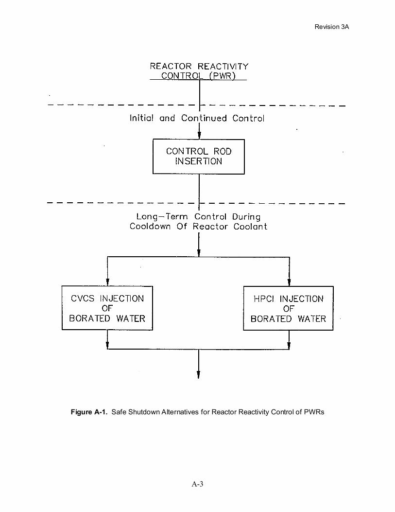
The safe shutdown alternatives for accomplishing the reactor reactivity control function for
PWRs are illustrated in the block diagram shown in Figure A-l; these alternatives are described
below.
Generally, nuclear plants have two methods for controlling reactivity. The primary method for
shutting down the nuclear reaction (inserting negative reactivity) is by control rod insertion
(SCRAM). A second method is the rapid addition of liquid neutron poison, typically boron, to
the reactor coolant; this method requires a minimum of 10 to 15 seconds to inject sufficient
Revision 3A
A-2
neutron poison into the reactor coolant system to make the core subcritical without control rod
insertion. While both methods are available for emergency shutdown, it is considered that, from
a practical standpoint, fast control rod insertion (SCRAM) should be available for initial reactor
shutdown during and after an earthquake; therefore, the control rods and associated control rod
insertion mechanisms and systems are considered essential for safe shutdown. Since reactors are
designed to shut down with one control rod not inserted, this method meets the single failure
criteria.
In addition to control rod insertion, reactors also typically require supplemental long-term
reactivity control by the addition of liquid poison to the reactor coolant system. This long-term
control is needed to compensate for the combined effects of positive reactivity increases
resulting from Xenon-135 decay and reduction of the reactor coolant temperature. Note that
some plants may need to compensate for significant reactor coolant temperature decreases to get
to the hot shutdown mode. Two methods are typically available for injection of borated water
into the reactor coolant system to compensate for these long-term, positive reactivity effects.
These safe shutdown alternatives include injection via the:
• Chemical and Volume Control System (CVCS), or
• High Pressure Coolant Injection (HPCI) system.
Revision 3A
A-3
Figure A-1. Safe Shutdown Alternatives for Reactor Reactivity Control of PWRs

Revision 3A
A-4
Figure A-2. Safe Shutdown Alternatives for Reactor Coolant Pressure Control of PWRs
Revision 3A
A-5
A.2.2 Reactor Coolant Pressure Control (PWR)
The safe shutdown alternatives for accomplishing the reactor coolant pressure control function
for PWRs are illustrated in the block diagram shown in Figure A-2; these alternatives are
described below along with the conditions under which they can be used. There are various
pressure-temperature limits which should not be exceeded in the reactor coolant system of
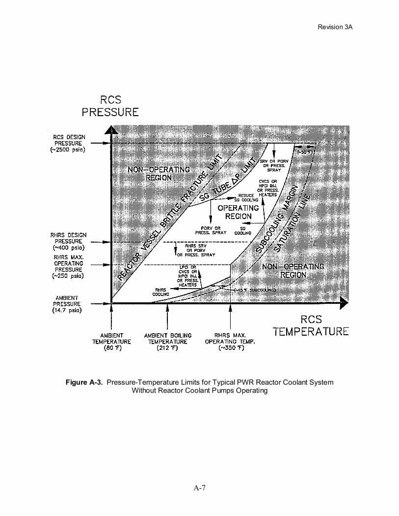
PWRs. These are illustrated in Figure A-3 where the unshaded area in the center of the figure is
the Operating Region for the reactor coolant system during and following an earthquake while
the reactor coolant pumps are not operating (loss of offsite power is assumed). The shape of the
curves and the values of pressure and temperature are approximate. Actual plant limits may be
different.
The methods which can be used to avoid exceeding the pressure-temperature limits are
illustrated in Figure A-3 by arrows within the Operating Region. These arrows indicate the
direction of change of the pressure and temperature when one of the indicated systems or
methods is used to avoid exceeding the limits.
The discussion below explains the various pressure-temperature limits and the methods which
can be used to avoid them:
The reactor coolant system design pressure (about 2500 psia) is the upper limit on pressure. The
pressurizer safety relief valves (SRVs) have the capability to prevent this limit from being
exceeded. Also, the power-operated relief valves (PORVs) on the pressurizer can be used to
lower the pressure throughout the Operating Region from 2500 psia down to ambient pressure.
In addition, reactor coolant system pressure can be reduced by spraying water into the steam
space of the pressurizer using an auxiliary spray system. (Normal spray is not available since the
reactor coolant pumps are not running due to the assumed loss of offsite power.)
The subcooling margin is another limit on the reactor coolant system pressure (and temperature).
It is required to avoid formation of a steam bubble within the reactor vessel. This limit, shown in
Figure A-3, is typically about 50°F of subcooling from the saturation line; this amount of
subcooling margin is used during natural circulation decay heat removal with the steam

Revision 3A
A-6
generators at secondary side pressures above about 250 psia. Less subcooling margin (about
15°F) is needed below this pressure to maintain sufficient net positive suction head (NPSH) on
the low pressure residual heat removal pumps.
The subcooling margins can be maintained by increasing the pressure of the reactor coolant
system. Above the maximum operating pressure of the residual heat removal system (RHRS)
(about 250 psia), the chemical and volume control system (CVCS) or the high pressure coolant
injection (HPCI) system can be used to inject water into the reactor coolant system and thereby
compress the steam bubble in the pressurizer and increase the system pressure. As an
alternative, the saturation temperature of the reactor coolant in the pressurizer can be increased
via pressurizer heaters and thereby raise the pressure. At lower pressures, the low pressure
coolant injection (LPCI) system also can be used. Note that injection of cool water into the
reactor coolant system also slightly reduces the overall bulk temperature of the reactor coolant.
As the water is cooled, it contracts slightly; this is shown by the leftward leaning arrows pointing
upward from the subcooling margin line.
Another method of maintaining adequate subcooling margin is to decrease the temperature of the
reactor coolant system by increasing the rate of decay heat removal as described in Section
A.2.4, Decay Heat Removal (PWR). For pressures above about 250 psia, natural circulation
decay heat removal via the steam generators (SGs) can be used. For pressures lower than this,
the residual heat removal system (RHRS) can be used.
The reactor vessel brittle fracture limit is another limit on reactor coolant system pressure (and
temperature). This limit can be avoided by lowering the reactor coolant system pressure by the
same methods described earlier.
Revision 3A
A-7
Figure A-3. Pressure-Temperature Limits for Typical PWR Reactor Coolant SystemWithout Reactor Coolant Pumps Operating

Revision 3A
A-8
Steam generator (SG) tube differential pressure (delta P) limit is another limit on reactor coolant
system pressure (and temperature). This limit can be exceeded by overpressurizing the ID of the
SG tube with the reactor coolant system without sufficient balancing pressure on the OD of the
tube for a given temperature. This limit can be avoided by lowering the reactor coolant system
pressure using the same methods described in the previous paragraphs.
One other method of avoiding the reactor vessel brittle fracture limit and the SG tube delta P
limit is to allow the temperature of the reactor coolant to rise by reducing the steam generator
(SG) cooling. This method is illustrated by the dashed arrow pointing to the right in the
operating region of Figure A-3; this arrow is sloping upward to show that as the reactor coolant
gets hotter, it also expands and increases the system pressure slightly.
The residual heat removal system (RHRS) design pressure (about 400 psia) should not be
exceeded after the residual heat removal system has been connected to the reactor coolant
system. In addition to all of the methods described above for lowering the reactor coolant
system pressure, the safety relief valves (SRVs) on the RHRS also can be used when the RHRS
is connected to the reactor coolant system. Note that it is not necessary to use the RHRS unless
the plant elects to go to cold shutdown.
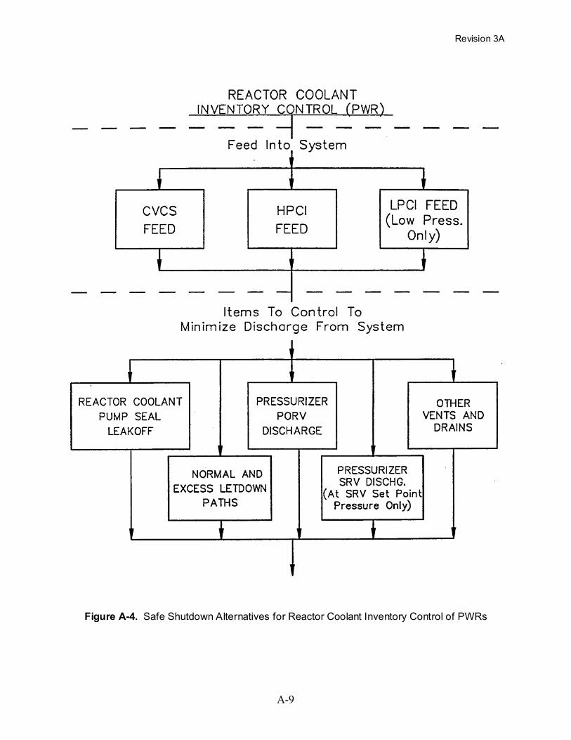
A.2.3 Reactor Coolant Inventory Control (PWR)
The safe shutdown alternatives for accomplishing the reactor coolant inventory control function
for PWRs are illustrated in the block diagram shown in Figure A-4; these alternatives are
described below.
The inventory of the reactor coolant system is controlled by feeding water into the system and by
minimizing the loss of water from the various openings in the system. Note that the alternatives
for reactor coolant inventory control are directly related to some of the alternatives for reactor
coolant pressure control, e.g., adding water to the reactor coolant system increases the system
pressure while removing steam (decreasing inventory) decreases the pressure. Therefore many
of the same alternatives are used for both of these safe shutdown functions.
Revision 3A
A-9
Figure A-4. Safe Shutdown Alternatives for Reactor Coolant Inventory Control of PWRs

Revision 3A
A-10
Feed Into the Reactor Coolant System (PWR). Typically, there are three safe shutdown
alternatives available for feeding the reactor coolant system:
• Chemical and Volume Control System (CVCS),
• High Pressure Coolant Injection (HPCI) system, or
• Low Pressure Coolant Injection (LPCI) system (at low pressure only).
The CVCS and HPCI systems can be used to control the reactor coolant inventory at both high
and low system pressure. The HPCI system in some plants does not have the capability to inject
reactor coolant at normal system pressure (about 2250 psia) but can do so at a somewhat lower
pressure (about 1600 psia). The LPCI system can only inject reactor coolant into the system at
pressures below about 250 psia, depending upon the plant-specific design.
Discharge From the Reactor Coolant System (PWR). There are several paths through which
reactor coolant can leave the reactor coolant system. Listed below are typical discharge paths
which should be controlled to minimize loss of inventory:
• Reactor Coolant Pump Seal1 Leakoff,
• Normal and Excess Letdown Paths,
• Pressurizer Power-Operated Relief Valves (PORVs),
• Pressurizer Safety Relief Valves (SRVs) (only at pressures at or above the SRV set point),and
• Other Vents and Drains.
1 Note that the reactor coolant pump seals may need a supply of water for cooling (closed cooling,
injection, or both) to maintain their integrity while the reactor coolant system is at elevated pressure. Ifthese services are not included in the selected safe shutdown approach, the consequences of seal failureleakage should also be addressed with adequate makeup capacity.

Revision 3A
A-11
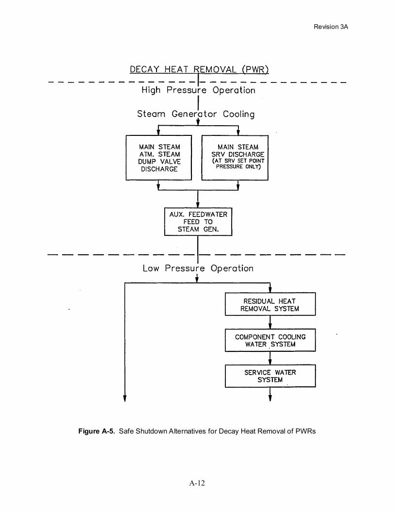
A.2.4 Decay Heat Removal (PWR)
The safe shutdown alternatives for accomplishing the decay heat removal function for PWRs are
illustrated in the block diagram shown in Figure A-5; these alternatives are described below.
While the reactor coolant system is at high pressure the steam generators can be used for
removing decay heat from PWRs. After the reactor coolant system pressure is lowered
sufficiently, the residual heat removal system can also be used.
To remove decay heat via the steam generators, it is necessary to establish natural circulation of
reactor coolant between the core (heat source) and the steam generators (heat sink). It is
assumed that the reactor coolant pumps are unavailable since they rely upon the use of offsite
power. Natural circulation normally requires the reactor coolant to be subcooled to minimize
void formation within the reactor vessel (as described in Section A.2.2, Reactor Coolant Pressure
Control). After natural circulation is established, heat can be removed from the reactor coolant
by boiling the feedwater on the secondary side of the steam generators. The steam generated
from this boiling can be discharged to the atmosphere through the main steam atmospheric steam
dump valves. The main steam safety valves (SRV) also can be used to discharge steam if the
secondary side pressure is allowed to go up to the SRV set point. Condenser steam dumps are
not available due to the assumed loss of condenser circulating water pumps, which are driven
from offsite power.
Makeup feedwater can be supplied to the secondary side of the steam generator via the
emergency/auxiliary feedwater (AFW) system. The condensate storage tank (CST) is the
preferred source of auxiliary feedwater with the service water system (SW) typically available as
a backup.
Revision 3A
A-12
Figure A-5. Safe Shutdown Alternatives for Decay Heat Removal of PWRs
Revision 3A
A-13
The reactor coolant temperature and pressure can be lowered by manually lowering the steam
generator secondary side pressure using the atmospheric steam dump valve. In some plants,
decay heat removal via the steam generators can continue at low reactor coolant system pressure
and temperature; however, in other plants, it is difficult to continue this natural circulation mode
of decay heat removal after the reactor coolant system pressure and temperature have dropped
below about 250 psia and 350°F. In these cases a low pressure decay heat removal system can
be used.
If it is preferred (or required due to certain plant limitations) to bring the plant to a cold
shutdown condition, the residual heat removal system (RHRS) can be used to remove decay heat
from the core after the reactor coolant system pressure and temperature are typically below about
250 psia and 350°F. There is considerable variation in the design of this system both among
reactor vendors and as a result of evolution of each vendor's design; however, this system
typically consists of pumps which take suction from the reactor coolant system, circulate the
water through heat exchangers, and inject the water back into the reactor coolant system. Heat is
transferred from the RHRS heat exchangers to the closed loop, component cooling water (CCW)
system which has its own set of pumps for circulating water. Heat is transferred from the CCW
system to the service water (SW) system in another heat exchanger and from there to the ultimate
heat sink (e.g., lake, river, or atmosphere).
A.3 DETAILED DESCRIPTION OF SAFE SHUTDOWN ALTERNATIVES FOR BWRS
Boiling water reactors (BWRs) typically have several paths or methods which can be used to
bring the plant to a safe shutdown condition. Typical alternative methods for accomplishing the
four safe shutdown functions (reactor reactivity control, reactor coolant pressure control, reactor
coolant inventory control, and decay heat removal) are described in detail in this section for
BWRs.

Revision 3A
A-14
A.3.1 Reactor Reactivity Control (BWR)
The safe shutdown alternative for accomplishing the reactor reactivity control function for
BWRs is illustrated in the block diagram shown in Figure A-6. Although two independent
methods are available for reactivity control during reactor shutdown conditions, control rod drive
system and standby liquid control system, the control rod drive system is the preferred method.
Control Rod Drive System (BWR). The control rod drive (CRD) system is the primary method
of reactivity control and is the only method capable of rapid shutdown (SCRAM) of the reactor
or operational control of fast reactivity transients. For this reason, the CRD system is considered
an essential safe shutdown system. The CRD system is used to manually position neutron
absorbing control rods in the reactor core and acts automatically to rapidly insert the control rods
when required.
The CRD mechanism consists of a double-acting, mechanically latched, hydraulic cylinder
which uses demineralized water from the condensate storage tank or condenser hotwell as the
operating fluid. A separate hydraulic control unit is provided for each individual control rod.
The CRD hydraulic system supplies and controls the pressure and flow requirements to the drive
mechanisms.
Each CRD drive mechanism is connected to a SCRAM accumulator tank pressurized with
nitrogen. The SCRAM accumulator tank stores sufficient energy to fully insert the control rod
independent of any other source of energy; i.e., pneumatic, AC, or DC power. During SCRAM,
accumulator pressure is admitted below the drive piston and the volume over the drive piston is
vented to the SCRAM discharge volume tank. The large differential pressure across the drive
piston produces a large upward force on the control rod to insert the control rod into the core.

Revision 3A
A-15
Figure A-6. Safe Shutdown Alternatives for Reactor Reactivity Control of BWRs

Revision 3A
A-16
Standby Liquid Control System (BWR). The standby liquid control (SLC) system provides a
backup method of reactivity control. The SLC system will shut down the reactor from full
power to cold shutdown in the event the control rods are inoperable. The SLC system is
manually initiated from the control room and pumps a neutron absorbing solution (sodium
pentaborate) into the reactor vessel. The injection time is approximately 1 to 2 hours, depending
on the pump capacity and the amount of solution in the tank. The SLC system is only required to
shut down the reactor at a steady state within the capacity of the normal shutdown cooling
systems. The SLC system is not capable of rapid shutdown (SCRAM) of the reactor or
operational control of fast reactivity transients. Since the CRD system is required and is
sufficient to achieve and maintain reactor shutdown in BWRs during and after an earthquake, the
SLC system is not considered an essential safe shutdown system in BWRs.
A.3.2 Reactor Coolant Pressure Control (BWR)
The safe shutdown alternatives for accomplishing the reactor coolant pressure control function
for BWRs are illustrated in the block diagram shown in Figure A-7; these alternatives are
described below.
Overpressure protection of the reactor coolant system is provided by safety relief valves and
safety valves located on the main steam lines in the drywell. The safety relief valves are self-
actuated by the reactor coolant system pressure to open at their set relieving pressure. Typically,
the safety relief valves are set to open at a lower pressure than the safety valves. The safety
relief valves discharge steam directly to the suppression pool. Also, they may be actuated
remotely from the control room to open at lower pressures to depressurize the reactor coolant
system so that low pressure systems can be used for reactor coolant inventory control and decay
heat removal. In addition, some of the safety relief valves open automatically during certain
LOCAs in the event the high pressure core cooling systems are unavailable or are unable to
maintain acceptable reactor water level above the core.

Revision 3A
A-17
Figure A-7. Safe Shutdown Alternatives for Reactor Coolant Pressure Control of BWRs

Revision 3A
A-18
The safety valves are spring-loaded valves which are self-actuated by the reactor coolant system
pressure to open at the set relieving pressure. The safety valves are set to open at a higher
pressure than the safety relief valves, and, in conjunction with the safety relief valves, protect the
reactor coolant system from severe pressure transients. The safety valves generally discharge to
the drywell.
Safety valves on the low pressure residual heat removal system also can be used during low
pressure decay heat removal to prevent the reactor coolant system pressure from exceeding the
design pressure of the low pressure system.
A.3.3 Reactor Coolant Inventory Control (BWR)
The safe shutdown alternatives for accomplishing the reactor coolant inventory control function
for BWRs are illustrated in the block diagram shown in Figure A-8; these alternatives are
described below.
During reactor shutdown conditions, makeup water to the reactor coolant system is required to
replace steam released through the safety relief valves and safety valves, to make up for leakage
from the reactor coolant system (i.e., recirculation pump seals, normal unidentified leakage, etc.),
and to compensate for the contraction of the reactor coolant system volume due to cooldown.
The following high and low pressure systems are available for supplying makeup water to the
reactor vessel.
High Pressure Systems (BWR). Available high pressure systems consist of the following:
1. High Pressure Coolant Injection (HPCI) System, or High Pressure Core Spray (HPCS)System (BWR). BWRs will have only one of these two high pressure injection systems.Most older BWRs have HPCI systems while the newer BWRs have HPCS systems.
The HPCI system uses a steam turbine-driven pump to pump water the condensate storagetank into the feedwater system. Water is injected into the reactor vessel through thefeedwater sparger. On low condensate storage tank level or high suppression pool level,the pump suction is automatically transferred to the suppression pool. Manual transfermay also be made from the control room.

Revision 3A
A-19
Figure A-8. Safe Shutdown Alternatives for Reactor Coolant Inventory Control of BWRs

Revision 3A
A-20
The HPCS system uses a motor-driven pump to pump water from the condensate storagetank into the reactor vessel through a spray header located inside the reactor vessel. Onlow condensate storage tank level or high suppression pool level, the pump suction isautomatically transferred to the suppression pool. Manual transfer may also be made fromthe control room.
2. Reactor Core Isolation Cooling System (BWR). The reactor core isolation cooling (RCIC)system uses a steam turbine-driven pump to pump water from the condensate storage tankinto the feedwater system. Water is injected into the reactor vessel through the feedwaterAnother source of water is the suppression pool in the event the condensate storage tankbecomes depleted. The RCIC system is provided on older BWRs with isolation condensersystems.
3. Control Rod Drive Hydraulic System (BWR). Another source of high pressure water isfrom the control rod drive (CRD) hydraulic system. The CRD hydraulic system isrelatively limited in capacity (approximately 100 gpm), but can provide sufficient makeupto maintain reactor vessel water level after the reactor has been shutdown for several hours.In some plants, the CRD hydraulic system may not be available to-perform safe shutdownfunctions due to reliance on offsite AC power to operate the electric-driven CRD pumps.
The earliest BWRs (e.g., Oyster Creek, Nine Mile Point 1, and Millstone 1) have feedwatercoolant injection (FWCI) systems instead of HPCI or HPCS systems. The FWCI systemuses the electric-driven main feedwater pumps to pump water into the reactor vessel via themain feedwater system; however, the FWCI system is considered unavailable forperforming safe shutdown functions due to its reliance on offsite AC power for the mainfeedwater pumps. Thus, these plants must use the CRD hydraulic system or the reactorcoolant system must be depressurized so that low pressure systems can be used for reactorcoolant inventory control.
Low Pressure Systems (BWR). The Automatic Depressurization System (ADS) may be used in
conjunction with low pressure systems to supply makeup water to the reactor vessel. The ADS
may be remotely manually actuated from the control room. The ADS depressurizes the reactor
vessel by releasing steam to the suppression pool through the safety relief valves. Available low
pressure systems consist of the following:
1. Low Pressure Coolant Injection System (BWR). The low pressure coolant injection(LPCI) system uses the electric-driven residual heat removal (RHR) pumps to pump waterfrom the suppression pool to the reactor vessel through a recirculation line. The LPCIsystem is not provided on some of the early BWRs.
2. Low Pressure Core Spray System (BWR). The low pressure core spray (LPCS) systemuses electric-driven pumps to pump water from the suppression pool to the reactor vesselthrough a spray header located inside the reactor vessel.
Revision 3A
A-21
Discharge From Reactor Coolant System (BWR). There are several paths through which reactor
coolant can leave the reactor coolant system. Listed below are typical discharge paths which
should be controlled to minimize loss of inventory:
• Safety Relief Valves (SRV),
• Letdown Paths, and
• Other Vents and Drains.
A.3.4 Decay Heat Removal (BWR)
The safe shutdown alternatives for accomplishing the decay heat removal function for BWRs are
illustrated in the block diagram shown in Figure A-9; these alternatives are described below.
The following high and low pressure systems are available to remove reactor core decay heat
following reactor shutdown.
High Pressure Systems (BWR). The high pressure systems typically available to remove reactor
core decay heat are as follows:
1. Isolation Condenser (IC) System or Reactor Core Isolation Cooling (RCIC) System(BWR). Early BWRs have an IC system to remove decay heat in the event the reactorbecomes isolated from the main condenser. Later BWRs have the RCIC system.
The IC system consists of a large vessel filled with water with an internal U-tube bundlewhich is connected by piping to the reactor vessel. Isolation valves (one AC powered andone DC powered) are provided on the steam supply and condensate return lines.Normally, the isolation valves on the steam supply lines are open so that the steam supplyline, condenser tubes, and condensate return line are pressurized at reactor pressure. TheAC isolation valve in the condensate return line normally is open and the DC valvenormally is closed. The system is placed in operation by opening the normally closed DCisolation valve in the condensate return line. Thus, AC power is not required to place thissystem in operation. Steam flows by natural circulation from the reactor vessel to theisolation condenser where it is condensed and cooled by boil-off of water on the shell sideof the condenser to the atmosphere. The condensate returns to the reactor vessel throughthe condensate return line which connects with the reactor recirculation system. Makeupto the shell side of the isolation condenser is normally from the condensate storage tank ora dedicated makeup storage tank. In addition, most plants can also supply makeup water tothe shell side of the isolation condenser by alternate methods (e.g., from the fire protectionsystem, suppression pool, etc.).

Revision 3A
A-22
Figure A-9. Safe Shutdown Alternatives for Decay Heat Removal of BWRs
Revision 3A
A-23
The RCIC system consists of a steam turbine-driven injection pump and associated piping,valves, and controls. Core decay heat is removed by releasing steam through the safetyrelief valves to the suppression pool. Suppression pool cooling is provided via the residualheat removal (RHR) heat exchangers. The RHR heat exchangers are cooled by the reactorbuilding closed cooling water (RBCCW) system which is cooled by the emergency servicewater (ESW) system. Makeup to the reactor vessel is provided by the RCIC pump whichuses steam produced in the reactor vessel to pump demineralized water from thecondensate storage tank to the feedwater system. The feedwater system provides a directflow path to the reactor vessel. Another source of water is the suppression pool in theevent the condensate storage tank becomes depleted.
In newer BWRs, the steam condensing mode of the RHR system may be manually initiatedapproximately 1.5 hours after reactor shutdown. In this mode, steam is routed through oneof the RHR heat exchangers where it is condensed and cooled, then returned to the reactorvessel by an interconnection with the RCIC pump, providing closed loop cooling.
2. High Pressure Coolant Injection (HPCI) System or High Pressure Core Spray (HPCS)System (BWR). Early BWRs used the HPCI system. In later BWRs, the HPCI systemwas replaced with the HPCS system. The HPCI and HPCS systems are designed to protectthe core in the event of a LOCA. The HPCI and HPCS systems also may be used for long-term decay heat removal following reactor shutdown. Core decay heat is removed byreleasing steam through the safety relief valves to the suppression pool. Suppression poolcooling is provided via the RHR heat exchangers. The RHR heat exchangers are cooled bythe RBCCW system which is cooled by the ESW system. Makeup to the reactor vessel isprovided by the HPCI or HPCS injection pumps. The HPCI pumps are steam turbine-driven and pump demineralized water from the condensate storage tank to the feedwatersystem. The feedwater system provides a direct flow path to the reactor vessel. The HPCSpumps are electric-driven and pump demineralized water from the condensate storage tankto a spray header located inside the reactor vessel. On low condensate storage tank level,the HPCI and HPCS pump suctions are automatically transferred to the suppression pool.
Low Pressure Systems (BWR). If desired, the reactor coolant system may be depressurized
manually by using the Automatic Depressurization System (ADS) to release steam through the
safety relief valves to the suppression pool. This will allow the use of the following low pressure
systems for long-term decay heat removal.
1. Shutdown Cooling (SC) System or Residual Heat Removal (RHR) System (BWR). EarlyBWRs contained a separate low pressure SC system for removal of core decay heatfollowing reactor shutdown. In later BWRs, the SC system was replaced with the RHRsystem which can be operated in several different modes to accomplish the following:
• Shutdown cooling
• Low pressure coolant injection
Revision 3A
A-24
• Vessel head spray cooling
• Suppression pool cooling
• Containment cooling
The SC system uses electric-driven pumps to circulate reactor coolant from the reactorrecirculation system to the SC heat exchangers and back to the recirculation system. Theshutdown cooling heat exchangers are cooled by the RBCCW system which is, cooled bythe ESW system.
The shutdown cooling mode of the RHR system operates in a similar manner; i.e., reactorcoolant is circulated from the recirculation system through the RHR heat exchangers andback to the recirculation system using electric-driven RHR pumps. The RHR heatexchangers are cooled by the RBCCW system which is cooled by the ESW system.
2. Low Pressure Coolant Injection System (BWR). The low pressure coolant injection(LPCI) mode of the RHR system also can be used for long-term decay heat removal at lowpressure following reactor shutdown. Core decay heat is removed by releasing steamthrough the safety relief valves to the suppression pool. Suppression pool cooling is viathe RHR heat exchanger. The RHR heat exchangers are cooled by the RBCCW systemwhich is cooled by the ESW system. Makeup to the reactor vessel is provided by theelectric-driven LPCI injection pumps (which are actually RHR pumps). In the LPCI mode,water is pumped by the RHR pumps from the suppression pool to the reactor recirculationsystem.
3. Low Pressure Core Spray System (BWR). The low pressure core spray (LPCS) systemprovides another redundant method of removing core decay heat at low pressure followingreactor shutdown. Core decay heat is removed by releasing steam through the safety reliefvalves to the suppression pool. On early BWRs with a separate shutdown cooling systeminstead of the multi-purpose RHR system, the suppression pool is cooled via thecontainment spray heat exchangers. The containment spray heat exchangers are cooled bythe RBCCW system which is cooled by the ESW system. On later BWRs with the multi-purpose RHR system, the suppression pool is cooled via the RHR heat exchangers. TheRHR heat exchangers are cooled by the RBCCW system which is cooled by the ESWsystem. Makeup to the reactor vessel is provided by the LPCS electric-driven pumpswhich pump water from the suppression pool to a spray header inside the reactor vessel.
A.4 STEP-BY-STEP PROCEDURE FOR IDENTIFYING SAFE SHUTDOWNEQUIPMENT
This section describes a step-by-step procedure for:
• Identifying the major system alternatives available for achieving and maintaining safeshutdown conditions at a nuclear power plant,

Revision 3A
A-25
• Selecting preferred safe shutdown alternatives for the primary and backup means of safeshutdown, and
• Identifying all the equipment required by the preferred safe shutdown alternatives.
The approach taken in this procedure is to identify the major system alternatives and then select a
preferred major system alternative or shutdown train for the primary and backup means of safe
shutdown. Only the equipment in these preferred alternatives need to be identified prior to the
seismic walkdown. The decision as to which alternatives should be selected can be made from a
high-level engineering evaluation conducted by a team of engineers with experience in the
mechanical and electrical systems of the plant and with background in seismic areas. Also, plant
operations and management should review the selection of the preferred safe shutdown
alternatives.
If desired, the equipment associated with other major system alternatives also can be identified
prior to the walkdown. This would provide additional flexibility during the walkdown in case
the seismic adequacy of certain equipment in the preferred paths cannot be easily verified.
The flow diagram in Figure A-10 (located at the end of this appendix) shows all the steps to be
taken in identifying the safe shutdown equipment in the plant. It is suggested that this figure be
referred to while reading this section. The steps in this procedure can be divided into three major
tasks.
• Identification of the primary and backup safe shutdown alternatives for each of the foursafe shutdown functions described in Section 3.4. The generic safe shutdown alternativesdescribed in Sections A.2 and A.3 of this appendix can be used as a guide. This major taskis shown in Steps 1 through 3 in Figure A-10.
• Identification of the equipment needed for each of the four safe shutdown functions andgeneration of a safe shutdown equipment list (SSEL) for each function. This major task isshown in Steps 4 through 16 in Figure A-10.
• Generation of a safe shutdown equipment list (SSEL) for the seismic evaluation and anSSEL for the relay evaluation from the SSELs generated above. This major task is shownin Steps 17 and 18 in Figure A-10.
Revision 3A
A-26
The sequence of steps in this procedure is to: (1) select one of the safe shutdown functions, (2)
identify the preferred safe shutdown alternative, and (3) identify the equipment in that
alternative. However, the user may wish to identify all the preferred alternatives for all four
functions prior to identifying the specific equipment in any of these alternatives; i.e., perform the
first major task (Steps 1 through 3) for all four functions prior to performing the remainder of the
procedure. Then, the results of this overall system selection process can be reviewed by utility
operations and management before proceeding with the detailed (and time consuming) process of
identifying the individual items of equipment.
The steps in this procedure include a description of how to document its implementation. Note
that the purpose of documenting these steps is to provide a systematic method of identifying all
the equipment needed for safe shutdown. The documentation identified by this procedure
includes: (1) a description of the plant-specific, preferred safe shutdown alternative and the
procedures which would be used for each safe shutdown function, (2) marked-up schematic
diagrams (fluid system P&IDs, electrical one-line diagrams, instrumentation block diagrams,
etc.), (3) safe shutdown equipment lists (SSELs) for each safe shutdown function and any other
SSELs for support systems, (4) an SSEL for seismic evaluation, and (5) an SSEL for relay
evaluation. Blank forms are provided in Exhibits A-l, A-3, and A-5 at the end of this appendix
for documenting the identification of equipment on SSELs; the discussion below describes how
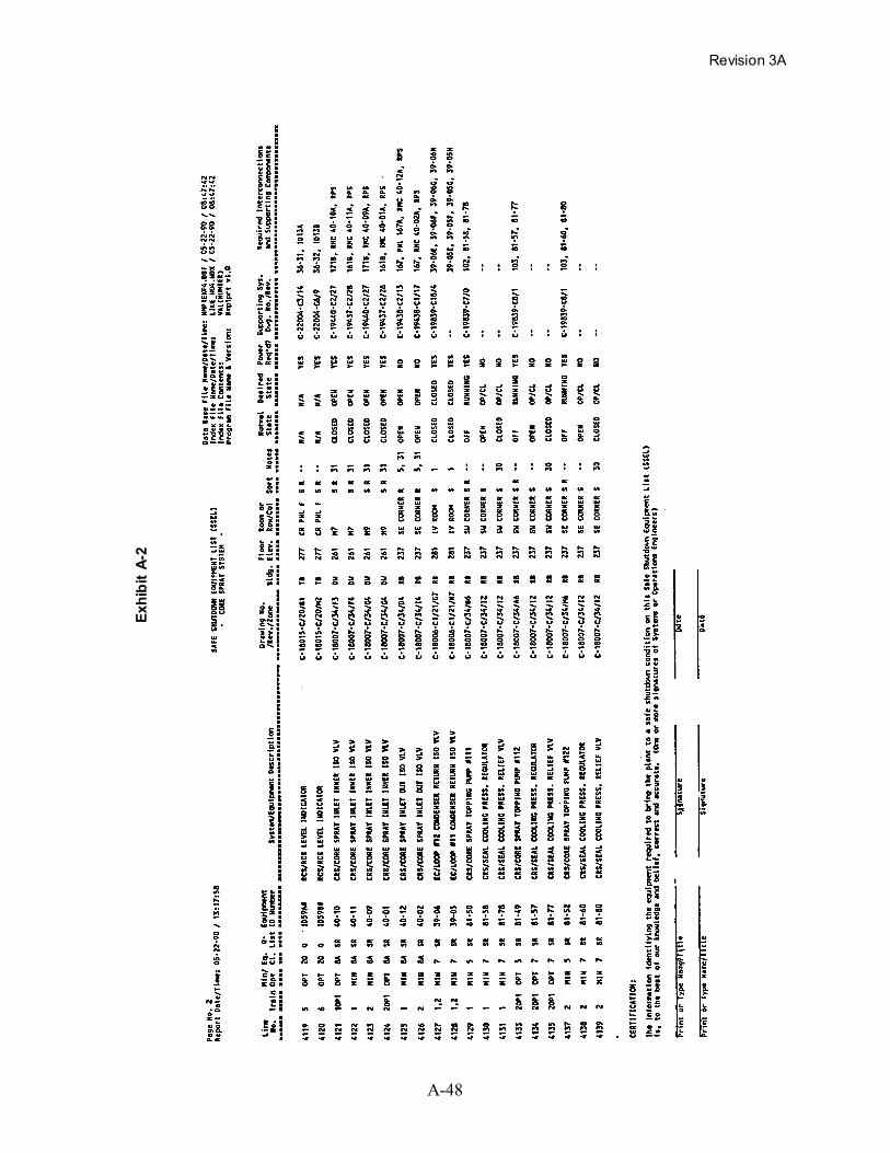
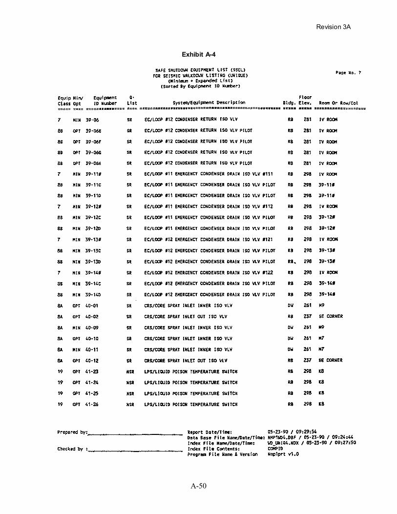
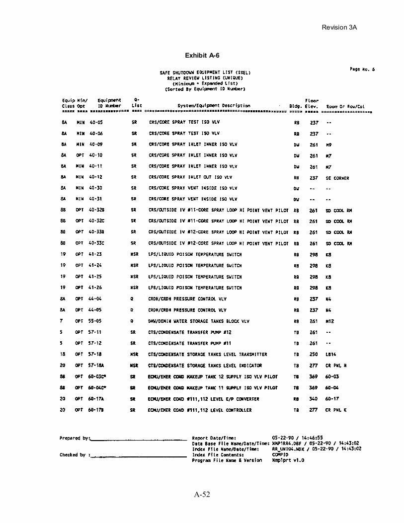
to fill out these forms. Exhibits A-2, A-4, and A-6 show these forms filled out with a database
management system.
The details for performing each of the steps shown in Figure A-10 are provided below. The
number and description within each box of the flow diagram in Figure A-10 correspond to the
step number and section title in the description below.
Step 1 - Pick a Safe Shutdown Function
The four safe shutdown functions which should be accomplished during and following a safe
shutdown earthquake are:
Revision 3A
A-27
• Reactor Reactivity Control
• Reactor Coolant Pressure Control
• Reactor Coolant Inventory Control
• Decay Heat Removal
One of these four functions should be selected on the first pass through this procedure.
Succeeding passes through this procedure should pick up the other three functions. A separate
SSEL should be generated for each of these four functions. In some cases a separate SSEL can
be generated for the primary and backup trains of equipment. Also, additional tables can be
generated for supporting systems which are common to several functions so that the same
equipment does not need to be duplicated on several tables. The form shown in Exhibit A-l can
be used for each of these SSELs.
Step 2 - Identify Paths Available
There are normally several alternatives for accomplishing each of the safe shutdown functions
selected in Step 1, above. In this step, various major system alternatives should be identified and
documented.
The description of each safe shutdown alternative should be similar to the descriptions of the
generic safe shutdown alternatives contained in Section A.2 or A.3 of this appendix. Plant-
unique equivalents to these generic alternatives also may be identified. These descriptions
should address how the systems used for each alternative can be put into operation including any
automatic controls and operator initiated actions using the plant procedures. Note that manual
initiation and verification of operation at a local station is an acceptable alternative to automatic
initiation and remote indication, provided time, manpower, and appropriate procedures are
available to use the local station.
Revision 3A
A-28
It should be noted that for each of the four safe shutdown functions, a backup or redundant item
of equipment or alternate method should be available for each active item of equipment in the
system being used.
Backup equipment need not necessarily be installed spares. Alternative means of providing
backup capability can include manual operation of power-operated equipment, substitution of a
temporary item of equipment (if enough time and procedures are available to bring it into
operation), or use of another safe shutdown alternative.
Completion of this step should result in the following:
• Descriptions of the safe shutdown alternatives for accomplishing the safe shutdownfunction.
• Descriptions of how the alternatives can be put into operation using the plant procedures.
The above results should be documented in a format similar to the descriptions shown in
Sections A.2 and A.3 of this appendix.
Step 3 - Pick a Primary/Backup Path
The purpose of this step is to review the various alternative methods for achieving safe shutdown
defined in Step 2 and to select a preferred method for either the primary or backup means of
shutdown. This selection can be based on one or a combination of the following considerations:
• The systems and equipment selected for shutting down the plant following a fire. It shouldbe noted, however, that the safe shutdown equipment identified for this procedure will notnecessarily be the same as equipment identified for 10 C.F.R. Part 50, Appendix R, for thesame general shutdown method.
• The alternatives which rely on the systems and equipment to operate in their normal mode.
• The alternatives which are straightforward and present the least challenge to the operators.
• The status of the seismic classification, design, and documentation for the equipment in thesafe shutdown alternative.

Revision 3A
A-29
• The results of previous seismic reviews and walkdowns.
• The location (elevation) of the equipment within the plant (the lower the elevation, thelower the seismic excitation).
• The operating procedures (normal or emergency) used to achieve and maintain safeshutdown conditions.
In addition, the following factors may also be considered:
• The practicality/difficulty and cost of returning the plant to normal operation after a SSE.
• The alternatives which minimize the amount of effort, expense, and radiation exposure toverify the seismic adequacy of the equipment.
Selection of the preferred safe shutdown alternatives requires a broad understanding of the
systems, equipment, and procedures used in the plant. This high-level selection process should
be reviewed by plant operations and management. Specific items of equipment within the
selected systems can then be identified by the systems engineer in the remaining steps of this
procedure.
Completion of this step will result in the following:
• Completed headings beneath the title on the SSEL (Exhibit A-l) with the followinginformation:
− Name of safe shutdown function for which equipment will be identified, forexample:
FUNCTION: Decay Heat Removal
− Description of alternative for accomplishing the safe shutdown function, forexample:
ALTERNATIVE: SG Cooling/AFW and Steam Dump Valves
• Description of the safe shutdown alternatives selected for accomplishing each of the foursafe shutdown functions. This summary should also identify the major steps in the
Revision 3A
A-30
procedures which would be used in bringing the selected safe shutdown equipment intooperation and continuing to operate it.
Step 4 - Identify an Item of Equipment
The preferred safe shutdown alternative identified in Step 3, above, typically will require several
different systems or parts of systems to operate. The purpose of this step is to trace the path of
fluid (or power, or cooling, etc.) from its source to its destination and identify one item of
equipment. The schematic diagram (fluid system P&ID, electrical system one-line diagram,
instrument block diagram, etc.) can be marked up with see-through markers or highlighters to
illustrate the path selected and to ensure that all branches and alternate paths are accounted for.
The equipment to be identified for safe shutdown should be one of the Equipment Classes #0
through #21 described in Table 3-l of Section 3. Equipment to be included in the safe shutdown
equipment list are those items of active mechanical and electrical equipment which should
operate or change state to accomplish the safe shutdown function selected in Step 1. It should
also include electrical equipment which should not inadvertently operate or change state due to
relay (contact) chatter. The equipment needed for supporting the safe shutdown equipment
should also be identified, such as, electrical power and control, pneumatic power and control,
cooling, lubrication, etc.; this is done in Steps 9, 10, 11, and 12.
The marked-up areas on the schematic diagram should extend up to, and include the isolation
valves in the main and branch lines which form the boundary of the system. The configuration
of the system used during normal operation of the plant should be used when marking the
diagram and identifying the boundary. It is optional whether passive items of equipment (other
than those for which a relay review is needed) are listed on the SSEL.
If the identified system is used differently by another safe shutdown alternative, a separate SSEL
should be generated and a separate schematic diagram should be marked up for that alternative.
Completion of this step should result in the following:

Revision 3A
A-31
• Marked-up schematic diagram (e.g., fluid system P&IDs, electrical system one-linediagrams, instrument block diagrams, etc.) for the identified system for one of the safeshutdown alternatives.
• Completed columns (1) through (6) and columns (10) and (11) of the SSEL with thefollowing information for the item of equipment:
Column No. Column Description 1 Table Line Number
2 Train or Backup Component Designation
3 Equipment Class (from Table 3-1)4 Equipment Identification Number (Plant Unique)
5 System Designation and Equipment Description6 Schematic Drawing Number and Zone. The schematic drawing number
and zone is optional. It can be used to help retrace the steps used inidentifying the safe shutdown equipment.
10 Type of Evaluation Needed, i.e., Seismic and/or Relay Review
11 Note Number. The note number is optional. Notes can be used todocument the reason why certain equipment was or was not included inthe safe shutdown equipment list.
Step 5 - Determine Location in Plant
The location of the item of equipment should be identified in this step. In some cases it may be
necessary to walkdown the plant to find where the equipment is located. The floor elevation
from which the equipment can be seen should be identified.
Completion of this step should result in the following:
Revision 3A
A-32
• Completed columns (7) through (9) of the SSEL with the following information for theitem of equipment.
Column No. Column Description
7 Building in Which Equipment is Located
8 Floor Elevation in Building From Which Equipment Can Be Seen. It issuggested that the floor elevation from which the equipment can be seenbe entered into this column for use in sorting equipment for laterwalkdown. The seismic review team should determine the actual plantelevation from which the equipment receives its seismic input (demand)during the plant walkdown (for input into the SVDS shown in Exhibit4-1, Column 7, Base Elevation).
9 Room or Row and Column Number Designation Where Equipment isLocated
Step 6 - Determine Normal State
The purpose of this step is to identify the normal operating state of the item of equipment
identified in Step 4 during normal operation of the plant. This information is often given on the
fluid system schematic diagrams (P&IDs); however, this information should be confirmed by an
operator familiar with the specific plant being evaluated.
Completion of this step should result in the following:
• Completed column (12), “Normal State,” of the SSEL with one of the followingconditions:
OPEN (Equipment is normally open)
CLOSED (Equipment is normally closed)
OP/CL (Equipment normally changes state from open to closed or from closedto open)
ON (Equipment is on and normally operating)
OFF (Equipment is off and normally not operating)
N/A (Not Applicable)
Revision 3A
A-33
Step 7- Determine Desired State
The purpose of this step is to identify the desired operating state of the equipment identified in
Step 4 to accomplish the safe shutdown function selected in Step 1. This operating state should
be confirmed by an operator familiar with the specific plant being evaluated.
Completion of this step should result in the following:
• Completed column (13), “Desired State,” in the SSEL with one of the followingconditions:
OPEN (Equipment should be open)
CLOSED (Equipment should be closed)
OP/CL (Equipment should change state from open to closed or from closed toopen)
ON (Equipment should be on and operating)
OFF (Equipment should be off and not operating)
N/A (Not applicable)
Step 8 - Is Power Needed?
This step asks whether the equipment identified in Step 4 needs an external source of power
(hydraulic, pneumatic, electrical) to operate, or if power is needed to control its operation so that
it can accomplish the safe shutdown function selected in Step 1. This information is used in
Step 9 to identify a power source and to decide whether a Seismic and/or Relay review is needed
(Column 10).
The answer to whether power is needed depends upon which of the following four categories the
equipment falls into. These categories depend upon whether the equipment is in the desired
operating state while the plant is at normal operation and whether the equipment will achieve the
desired operating state upon loss of operating or control power. These four categories and the
Revision 3A
A-34
answer as to whether operating or control power is needed are given below. The table at the end
of this description summarizes these categories.
1. The equipment is in the desired state to achieve the safe shutdown function, and upon lossof operating and/or control power, the equipment stays in the desired state. This wouldinclude valves which normally are open and fail open, valves which normally are closedand fail closed, and other active equipment (e.g., pumps, compressors, M-G sets, etc.)which normally are not running and fail in the not running state. Equipment in thiscategory does not need operating or control power to maintain the desired operating state;therefore, this equipment is not considered active and does not need to be seismicallyevaluated. However, to be sure that this equipment does not inadvertently becomeenergized and change state, this equipment should be identified for Relay review (Column10) and included as a line item on the SSEL if it is electrically-powered or -controlled sothat it can later (Step 18) be included on the SSEL for relay evaluation. For this categoryof equipment, skip Step 9 and proceed to Step 10.
2. The equipment is in the desired state to achieve the safe shutdown function, but upon lossof operating and/or control power, the equipment does not stay in the desired state. Thiswould include valves which normally are open and fail closed, valves which normally areclosed and fail open, and other active equipment which normally is running and fails in thenot running state. Equipment in this category does need operating power and perhaps alsocontrol power to maintain the desired operating state. This equipment is considered activeand should be seismically evaluated. Also, this equipment should be identified for Relayreview (Column 10) if it is electrically powered or controlled so that it can later (Step 18)be included on the SSEL for relay evaluation. For this category of equipment, proceed toStep 9.
3. The equipment is not in the desired state to achieve the safe shutdown function, but uponloss of operating and/or control power, the equipment will go to the desired state. Thiswould include valves which normally are open and fail closed, valves which normally areclosed and fail open, and other active equipment which normally is running and fails in thenot running state. Equipment in this category does need control power to assure thatoperating power will be cut off from the equipment to obtain the desired operating state.This equipment is considered active and should be seismically evaluated. Also, thisequipment should be identified for Relay review (Column 10) and included as a line itemon the SSEL if it is electrically-powered or -controlled so that it can later (Step 18) beincluded on the SSEL for relay evaluation. For this category of equipment, proceed toStep 9.
4. The equipment is not in the desired state to achieve the safe shutdown function, and uponloss of operating and/or control power, the equipment will not go to the desired state. Thiswould include valves which normally are open and fail open, valves which normally areclosed and fail closed, and other active equipment which normally is not running and failsin the not running state. Equipment in this category does need operating power andpossibly also needs control power to obtain the desired operating state. This equipment is
Revision 3A
A-35
considered active and should be seismically evaluated. Also, this equipment should beidentified for Relay review (Column 10) and included as a line item on the SSEL if it iselectrically-powered or -controlled so that it can later (Step 18) be included on the SSELfor relay evaluation. For this category of equipment, proceed to Step 9.
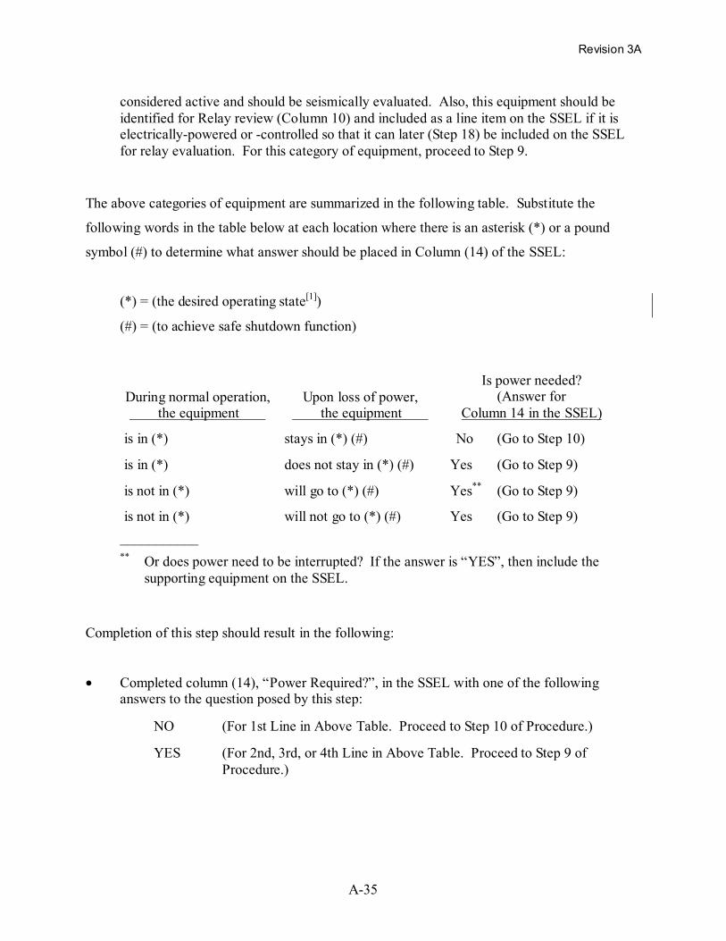
The above categories of equipment are summarized in the following table. Substitute the
following words in the table below at each location where there is an asterisk (*) or a pound
symbol (#) to determine what answer should be placed in Column (14) of the SSEL:
(*) = (the desired operating state[1])
(#) = (to achieve safe shutdown function)
During normal operation, the equipment
Upon loss of power, the equipment
Is power needed?(Answer for
Column 14 in the SSEL)
is in (*) stays in (*) (#) No (Go to Step 10)
is in (*) does not stay in (*) (#) Yes (Go to Step 9)
is not in (*) will go to (*) (#) Yes** (Go to Step 9)
is not in (*) will not go to (*) (#) Yes (Go to Step 9)___________** Or does power need to be interrupted? If the answer is “YES”, then include the
supporting equipment on the SSEL.
Completion of this step should result in the following:
• Completed column (14), “Power Required?”, in the SSEL with one of the followinganswers to the question posed by this step:
NO (For 1st Line in Above Table. Proceed to Step 10 of Procedure.)
YES (For 2nd, 3rd, or 4th Line in Above Table. Proceed to Step 9 ofProcedure.)
Revision 3A
A-36
Step 9 - Identify Power Sources
The purpose of this step is to identify the sources of power which are used to power and control
the equipment identified in Step 4. The main motive source of power to operate the equipment
or hold it in position and the control power for controlling this main motive force should be
identified. It is necessary to identify only the immediate source of power for the subject item of
equipment in this step. Subsequent passes through this section of the procedure will identify all
the items of equipment included in these sources of power; each one of these individual power
train items of equipment will later be included as a separate line item in the SSEL.
Completion of this step should result in the following:
• Completed column (15), “Supporting System Drawing Number,” in the SSEL with anyreference drawing number which identifies the power sources.
• Completed column (16) “Required Supporting Systems or Components,” in the SSEL withthe identification name and/or number of the power sources. For example, entries in thiscolumn could be:
AC BUS 622
DC BUS 212
PNEUMATIC
INSTR. BUS 211
MANUAL
-- (Equipment does not require power)
N/A (Not applicable)
Step 10 - Identify Supporting Systems and Components
The purpose of this step is to identify the supporting systems or components needed by the
equipment identified in Step 4 so that subsequent passes through this procedure can identify all
the equipment in these supporting systems. Supporting systems include such services as cooling,
lubrication, HVAC, etc.

Revision 3A
A-37
It is only necessary to identify the systems or components supporting the equipment in this step;
subsequent passes through this section of the procedure will identify all the equipment included
in a supporting system. Each of these individual items of equipment in a supporting system will
be included later as separate line items in the SSEL.
Completion of this step should result in the following:
• Completed column (15), “Supporting System Drawing Number,” in the SSEL with anyreference drawing number which identifies the supporting system.
• Completed column (16), “Required Supporting Systems or Components,” in the SSELwith the name of each system or component supporting the equipment identified in Step 4.For example, entries in this column could be:
PNEUMATIC
INST. AIR
SERV. AIR
MANUAL
CCW (Component Cooling Water System)
HVAC (Heating, Ventilating and Air Conditioning System)
-- (Equipment does not require any supporting system)
N/A (Not Applicable)
Step 11 - Identify Instruments for Function
To assure that the safe shutdown function selected in Step 1 is being accomplished, a number of
process variables should be measured. The purpose of this step is to identify the primary process
variables and instruments associated with the safe shutdown function defined in Step 1. For
example, to control the inventory in the reactor coolant system, the water level instrumentation
for the pressurizer (PWR), or the reactor vessel (BWR), should be identified as an essential
instrument. Note that other process variables and instruments, needed to control the individual
items of equipment, are identified in Step 12 of this procedure.

Revision 3A
A-38
For each process variable identified, a transmitter and its indicator (or recorder) should be listed
as line items on the SSEL (Exhibit A-l). For example, transmitters can be identified as either
Equipment Class 18 (Instrument Racks) or Class 19 (Temperature Sensors), while indicators (or
recorders) can be identified as Equipment Class 20 (Instrumentation and Control Cabinets) on
the SSEL.
Completion of this step should result in the following:
• Completed columns (1) through (11) and columns (14) through (16) of the SSEL with thefollowing information for the transmitters and indicators (or recorders):
Column No. Column Description
1 Table Line Number
2 Train or Backup Component Designation
3 Equipment Class (from Table 3-1)
4 Equipment Identification Number (Plant Unique)
5 System Designation and Equipment Description
6 Schematic Drawing Number and Zone. The schematic drawing numberand zone is optional. It can be used to help retrace the steps used inidentifying the safe shutdown equipment.
7 Building in Which Equipment is Located
8 Floor Elevation in Building From Which Equipment Can Be Seen. It issuggested that the floor elevation from which the equipment can be seenbe entered into this column for use in sorting equipment for laterwalkdown. The Seismic Review Team should determine, during theplant walkdown, the actual plant elevation from which the equipmentreceives its seismic input (demand).
9 Room or Row and Column Number Designation Where Equipment isLocated
10 Type of Evaluation Needed, i.e., Seismic and/or Relay Review
11 Note Number. The note number is optional. Notes can be used todocument the reason why certain equipment was or was not included inthe safe shutdown equipment list.

Revision 3A
A-39
Column No. Column Description
14 Is Power Required to Attain or Maintain the Desired Operating State orCondition? (Yes or No)
15 Reference Drawing Number for Supporting Power
16 Power Source Identification Number for the Instrument
Step 12 - Identify Instruments For Control
The purpose of this step is to identify the essential process variables which should be measured
to control the operation of the equipment identified in Step 4. It is necessary to measure these
equipment-related process variables in addition to the primary process variables identified in
Step 11 for the reactor and reactor coolant system.
Note that only those process variables needed for controlling the subject item of equipment need
be identified. For example, it may be necessary to measure the level of water in a tank so that
the operator (or an automatic control system) knows when the suction should be transferred to
another tank. In this case, the tank level measurement is needed for the operation of a set of
valves which connect the two tanks to the pump suction; tank level should be identified as an
essential process variable for the operation of these valves.
Note that this step only identifies the process variables to be measured; identification of the
transmitters and indicators (or recorders) will be done during subsequent passes through this
procedure. It is necessary, however, to have an understanding of the available instruments in the
plant so that appropriate process variables can be identified.
Completion of this step should result in the following:
• Completed column (15), “Supporting System Drawing Number,” in the SSEL with anyreference drawing number which identifies the instruments which can be used to measurethe process variables.
Revision 3A
A-40
• Completed column (16), “Supporting Systems or Components,” in the SSEL with thename of each process variable to be measured for controlling the change in operating stateof the equipment identified in Step 4. For example, entries in this column could be:
RC P (Reactor coolant pressure)
SG A LVL (Steam generator A level)
-- (Equipment does not require any process variables to be measured tocontrol its operation)
N/A (Not Applicable)
Step 13 - Is All Equipment Identified?
This step asks whether all the equipment (mechanical equipment, electrical equipment,
instrumentation, controls, tanks, and heat exchangers) have been identified which are needed to
accomplish the safe shutdown function selected in Step 1. To answer this question, the
schematic diagrams, being marked up in Step 4, should be reviewed to determine whether all the
equipment has been identified.
Step 14 - Are All Power/Support Systems Identified?
This step asks whether all the individual items of equipment for power, control, instrumentation,
and other supporting systems have been identified which are needed to accomplish the safe
shutdown function selected in Step 1.
One approach for systematically identifying all the equipment is to first identify all the
equipment on the fluid system schematic diagrams and enter them as line items in the SSEL.
Next, trace all the operating and control power equipment listed in column (16) using the
electrical one-line diagrams and enter these as separate line items in the SSEL. Then, the
transmitters and indicators (or recorders) should be identified from the list of process variables
listed in column (16) of the SSEL. Finally, the equipment contained in any supporting systems
listed in column (16) of the SSEL should be added as additional line entries in the SSEL. This

Revision 3A
A-41
process of adding equipment to the SSEL should continue until all the equipment contained in
the systems listed in column (16) are entered as line items.
Note that it may be convenient to use separate tables for some of the supporting systems since
they support several safe shutdown functions. For example, the emergency diesel generators
could be needed for both the decay heat removal function and the inventory control function.
Using a separate SSEL for the supporting systems would eliminate the need for repeating these
entries in several different tables.
If additional equipment should be added to the SSEL, then go back to Step 4, identify another
item of equipment, and add it to the list. However, if all equipment and instruments have been
identified for accomplishing the safe shutdown function selected in Step 1, then continue on to
Step 15.
Step 15 - Are Primary and Backup Paths Considered?
This step asks whether both the primary and the backup equipment or trains have been identified
to accomplish the safe shutdown function selected in Step 1. To answer this question, each item
of equipment in the primary SSEL should be reviewed to determine whether another backup item
of equipment or another backup train of equipment has been identified.
If the backup equipment and instruments have not been identified, then go back to Step 3 and
select a backup safe shutdown alternative. Note that it may be convenient to use a separate
SSEL for the backup equipment or train and to mark the schematic drawings with a different
color highlighter to distinguish between primary and backup.
If the backup equipment and instruments have been identified for each item of equipment in the
primary safe shutdown alternative, then continue on to Step 16.
Revision 3A
A-42
Step 16 - Are All Four Functions Evaluated?
This step asks whether all four of the safe shutdown functions have been evaluated for safe
shutdown equipment. If they have not all been evaluated, then go back to Step 1 and select
another safe shutdown function to evaluate. A new SSEL should be generated for this new
function.
When the equipment for all four safe shutdown functions has been identified, then proceed to
Step 17.
Step 17 - Develop Seismic Review SSEL
The purpose of this step is to combine the various safe shutdown equipment lists, generated by
repeated application of Steps 1 through 16, into a single safe shutdown equipment list which can
be used as the basis for the seismic evaluation to be done in Section 4. This seismic review
SSEL should have only one line entry for each unique item of equipment. The SSELs generated
in Steps 1 through 16 typically contain some of the same equipment; this seismic review SSEL
should eliminate this duplication.
This seismic review SSEL should contain only equipment for which a Seismic review(s) or a
Seismic and a Relay review (S, R) is identified in column (10).
The seismic review SSEL contains the following columns of information, as shown in
Exhibit A-3:

Revision 3A
A-43
Column No. Column Description
1 Equipment Class (from Table 3-1)
2 Train or Backup Component Designation
3 Equipment Identification Number (Plant Unique)
4 System Designation and Equipment Description
5 Building in Which Equipment is Located
6 Floor Elevation in Building from Which Equipment Can Be Seen
7 Room or Row and Column Number Designation Where Equipment isLocated
Generating this seismic review SSEL can be done rather easily by using a computerized database
management program. A database program can also be used to generate subsets of this SSEL in
which the equipment can be sorted by equipment class, by equipment ID number, by location in
the plant, etc.
Step 18 - Develop Relay Review SSEL
The purpose of this step is to combine the various safe shutdown equipment lists (SSELs),
generated by repeated application of Steps 1 through 16, into a single safe shutdown equipment
list which can be used as the basis for the relay evaluation described in Section 6.
This relay review SSEL should contain the items of active equipment from the various earlier
SSELs which use electricity for power, control, or instrumentation and passive equipment which,
if they change state or inadvertently operate, could prevent one of the safe shutdown functions
from being accomplished. This SSEL should contain only equipment for which a Relay review
(R) or a Seismic and a Relay review (S, R) is identified in Column (10).
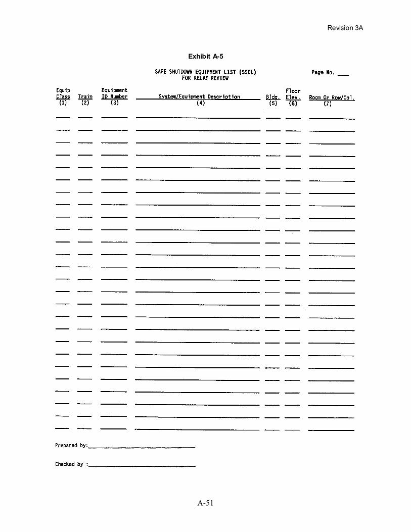
The relay review SSEL contains the following columns of information, as shown in Exhibit A-5:

Revision 3A
A-44
Column No. Column Description
1 Equipment Class (from Table 3-1)
2 Train or Backup Component Designation
3 Equipment Identification Number (Plant Unique)
4 System Designation and Equipment Description
5 Building in Which Equipment is Located
6 Floor Elevation in Building from Which Equipment Can Be Seen
7 Room or Row and Column Number Designation Where Equipment isLocated
Generating the relay review SSEL can be done rather easily by using a computer-based database
management program. A database program can also be used to generate subsets of this relay
evaluation SSEL in which the equipment can be sorted by equipment class, by equipment ID
number, by location in the plant, etc.

Revision 3A
A-45
Figure A-10. Steps for Identifying Safe Shutdown Equipment

Revision 3A
A-46
Exhibits A-1 to A-6 of Safe Shutdown Equipment Lists (SSELs)

Revision 3A
A-47
Exhi
bit A
-1
Revision 3A
A-48
Exhi
bit A
-2

Revision 3A
A-49
Exhibit A-3
Revision 3A
A-50
Exhibit A-4
Revision 3A
A-51
Exhibit A-5
Revision 3A
A-52
Exhibit A-6

Revision 3A
A-53
REASONS FOR CHANGES TO GIP, PART II, APPENDIX AListed below are the specific reasons for making the changes marked with a vertical line in the
margin of this appendix to create GIP-3A from GIP-3, Updated 5/16/97. The endnote numbers
listed below correspond to the bracketed numbers (e.g., [1]) located in the text of this appendix
where the changes are made.
1 Typographical error corrected.