
APPENDIX A ANNEX 10 — AERONAUTICAL ... working groups library...AMCP/7-WP/81 Appendix A to the...
41
AMCP/7-WP/81 Appendix A to the Report on Agenda Item 1 1A-1 APPENDIX A ANNEX 10 — AERONAUTICAL TELECOMMUNICATIONS VOLUME III (PART I — DIGITAL DATA COMMUNICATION SYSTEMS) NOTES ON THE PRESENTATION OF THE PROPOSED AMENDMENT TO ANNEX 10, VOLUME III, PART I The text of the amendment is arranged to show deleted text with a line through it and new text highlighted with grey shading, as shown below: 1. Text to be deleted is shown with a line through it. text to be deleted 2. New text to be inserted is highlighted with grey shading. new text to be inserted 3. Text to be deleted is shown with a line through it followed by the replacement text which is highlighted with grey shading. new text to replace existing text
Transcript of APPENDIX A ANNEX 10 — AERONAUTICAL ... working groups library...AMCP/7-WP/81 Appendix A to the...

AMCP/7-WP/81
Appendix A to the Report on Agenda Item 1 1A-1
APPENDIX A
ANNEX 10 — AERONAUTICAL TELECOMMUNICATIONS
VOLUME III
(PART I — DIGITAL DATA COMMUNICATION SYSTEMS)
NOTES ON THE PRESENTATION OF THE PROPOSED AMENDMENT TOANNEX 10, VOLUME III, PART I
The text of the amendment is arranged to show deleted text with a line through it and new text highlightedwith grey shading, as shown below:
1. Text to be deleted is shown with a line through it. text to be deleted
2. New text to be inserted is highlighted with grey shading. new text to be inserted
3. Text to be deleted is shown with a line through it followedby the replacement text which is highlighted with greyshading.
new text to replace existing text
AMCP/7-WP/81
1A-2 Appendix A to the Report on Agenda Item 1
CHAPTER 6. VHF AIR-GROUND DIGITAL LINK (VDL)
6.1 DEFINITIONS ANDSYSTEM CAPABILITIES
Note 1.— The very high frequency (VHF) digital link (VDL). Mode 2 and the VDL Mode 4 providedata service capabilities. The VDL Mode 3 provides both voice and data service capabilities. The datacapability is a constituent mobile subnetwork of the aeronautical telecommunication network (ATN),operating in the aeronautical mobile VHF frequency band. In addition, the VDL may provide non-ATNfunctions such as, for instance, digitized voice. The very high frequency (VHF) digital link (VDL)Standards and Recommended Practices (SARPs) for the VDL are defined and referenced below applyto aeronautical VHF digital communications systems operating within the aeronauticaltelecommunication network (ATN).
Note 2.— Additional information on VDL is contained in the Manuals on VDL Mode 2, VDL Mode3 and VDL Mode 4 Technical Specifications.
Note 3.— Sections 6.1.2 to 6.8.2 contain Standards and Recommended Practices for VDL Modes 2and 3. Section 6.9 contains Standards and Recommended Practices for VDL Mode 4.
Note 4.— VDL Mode 4 SARPs apply to surveillance applications (e.g. ADS-B and ADS-C).6.1.1 Definitions
Aeronautical telecommunications network. An internetwork architecture that allows ground, air-ground,and aircraft data subnetworks to interoperate by adopting common interface services and protocols basedon the International Organization for Standardization (ISO) Open Systems Interconnection (OSI)Reference Model.
Aircraft address. A unique combination of 24 bits available for assignment to an aircraft for the purpose ofair-ground communications, navigation and surveillance.
Asynchronous balanced mode. A balanced operational mode in which a data link connection has beenestablished between two service access points. Either data link entity can send commands at any timeand initiate responses without receiving permission from the peer data link entity on the connection.
Asynchronous disconnected mode. A balanced non-operational mode in which no logical data linkconnection exists between two link layer entities. A connection must be established before data can besent.
ATN router. An intermediate system used to interconnect subnetworks conforming to the lower three layersof the OSI reference model.
Automatic Dependent Surveillance-Broadcast (ADS-B). A surveillance application transmittingparameters, such as position, track and ground speed, via a broadcast mode data link for use by any airand/or ground users requiring it.

AMCP/7-WP/81
Appendix A to the Report on Agenda Item 1 1A-3
Note.— ADS-B is a surveillance service based on aircraft self-determination ofposition/velocity/time and automatic, periodic or random, broadcast of this information along withauxiliary data such as aircraft identity (ID), communications control parameters, etc. ADS-B isintended to support multiple high-level applications and associated services such as cockpit displayof traffic information, traffic alert and collision avoidance functionality, enhanced traffic managementin the air and on the ground, search and rescue support and others.
Autotune function. The function, performed by the link management entity, allows a ground station tocommand an aircraft to change frequencies.
Broadcast. A transmission intended to be received by all stations.
Broadcast handoff. The process by which a ground LME commands certain aircraft to execute a linkhandoff and optionally maintain its current subnetwork connections, without the need to explicitly confirmthe link handoff or optionally the subnetwork connection maintenance.
Broadcast link handoff. The process by which a ground LME commands certain aircraft to execute a linkhandoff to a specific ground station without the need to explicitly confirm the link handoff.
Broadcast subnetwork connection handoff. The process by which a ground LME commands certainaircraft to execute a link handoff to a specific ground station and maintain its current subnetworkconnections without the need to explicitly confirm the link handoff or the subnetwork connectionmaintenance.
Burst. A time-defined, contiguous set of one or more related signal units which may convey user informationand protocols, signalling, and any necessary preamble.
Current link (or current ground station). Either the ground-to-aircraft link or the active link when in theprocess of a handoff.
Current slot. The slot in which a received transmission begins.
Data circuit-terminating equipment (DCE). A DCE is a network provider equipment used to facilitatecommunications between DTEs.
Data link entity (DLE). A protocol state machine capable of setting up and managing a single data linkconnection.
Data link service (DLS) sub-layer. The sub-layer that resides above the MAC sub-layer. For VDL Mode 4,the DLS sub-layer resides above the VSS sub-layer. The DLS manages the transmit queue, creates anddestroys DLEs for connection-oriented communications, provides facilities for the LME to manage theDLS, and provides facilities for connectionless communications.
Data terminal equipment (DTE). A DTE is an endpoint of a subnetwork connection.

AMCP/7-WP/81
1A-4 Appendix A to the Report on Agenda Item 1
Effective data rate. The actual instantaneous data throughput realized after overheads imposed by bitstuffing and by any forward error correction encoding, but not retransmissions.
Expedited subnetwork connection establishment. The process by which an aircraft DTE establishes asubnetwork connection with a ground DTE with which it does not have a subnetwork connection duringlink establishment (or aircraft-initiated handoff) by inserting the CALL REQUEST packet and itsresponse in the link establishment (or aircraft-initiated handoff) frame and its response.
Expedited subnetwork connection maintenance. The process by which an aircraft or ground DTEmaintains a subnetwork connection with a DTE with which it has a subnetwork connection during linkhandoff by inserting the CALL REQUEST packet and its response in the link handoff frame and itsresponse.
Explicit subnetwork connection establishment. The process by which an aircraft DTE establishes asubnetwork connection with a ground DTE with which it does not have a subnetwork connection onlyafter completing the link establishment (or handoff).
Explicit subnetwork connection maintenance. The process by which an aircraft DTE maintains asubnetwork connection with a ground DTE with which it has a subnetwork connection only aftercompleting the link handoff.
Extended Golay Code. An error correction code capable of correcting multiple bit errors.
Frame. The link layer frame is composed of a sequence of address, control, FCS and information fields,. ForVDL Mode 2, these fields are bracketed by opening and closing flag sequences. A valid frame is at least11 octets in length and contains an address field (8 octets), a link control field (1 octet) and a frame checksequence (2 octets). A and a frame may or may not include a variable-length information field.
Gaussian filtered frequency shift keying (GFSK). A continuous-phase, frequency shift keying techniqueusing two tones and a Gaussian pulse shape filter.
Global signalling channel (GSC). A channel available on a world wide basis which provides forcommunication control.
Initiated handoff. The transmission process by which a station initiates link handoff.
Internetworking protocol. A protocol that transfers data packets between intermediate systems and endsystems interconnected by subnetworks and that is supported by the routing protocols and addressingplan.
Link. A link connects an aircraft DLE and a ground DLE and is uniquely specified by the combination ofaircraft DLS address and the ground DLS address. A different subnetwork entity resides above everylink endpoint.

AMCP/7-WP/81
Appendix A to the Report on Agenda Item 1 1A-5
Link establishment. The process by which an aircraft and a ground LME discover each other, determineto communicate with each other, decide upon the communication parameters, create a link and initializeits state before beginning communications.
Link handoff. The process by which peer LMEs, already in communication with each other, create a linkbetween an aircraft and a new ground station before disconnecting the old link between the aircraft andthe current ground station.
Link layer. The layer that lies immediately above the physical layer in the Open Systems Interconnectionprotocol model. The link layer provides for the reliable transfer of information across the physical media.It is subdivided into the data link sub-layer and the media access control sub-layer.
Link management entity (LME). A protocol state machine capable of acquiring, establishing, andmaintaining a connection to a single peer system. An LME establishes data link and subnetworkconnections, “hands-off” those connections, and manages the media access control sub-layer andphysical layer. An aircraft LME tracks how well it can communicate with the ground stations of a singleground system. An aircraft VME instantiates an LME for each ground station that it monitors. Similarly,the ground VME instantiates an LME for each aircraft that it monitors. An LME is deleted whencommunication with the peer system is no longer viable.
M burst. A management channel data block of bits used in VDL Mode 3. This burst contains signallinginformation needed for media access and link status monitoring.
Media access control (MAC). The sub-layer that acquires the data path and controls the movement of bitsover the data path.
Mode 2. A data-only VDL mode that uses D8PSK modulation and a Carrier Sense Multiple Access (CSMA)control scheme.
Mode 3. A voice and data VDL mode that uses D8PSK modulation and a TDMA media access controlscheme.
Mode 4. A data link using a gaussian-filtered frequency shift keying modulation scheme and self organizingtime division multiple access.
Multicast. A transmission intended to be received by multiple stations.
Network layer. The layer that provides the upper layers with independence from the data transmission androuting functions used to connect systems. The network layer is responsible for routing and relayingfunctions both within any subnetwork and throughout the aeronautical internetworking domain.
New link (or new ground station). After successful completion of handoff (or link establishment), the new“current” link.

AMCP/7-WP/81
1A-6 Appendix A to the Report on Agenda Item 1
N(r). The receive sequence number at the link layer, which indicates the sequence number of the nextexpected frame (and explicitly acknowledges all lesser numbered frames).
N(s). The send sequence number at the link layer, which indicates the sequence number associated with atransmitted frame.
Old link (or old ground station). Following link establishment during a handoff, the link that was previouslythe “current” link becomes the “old” link.
Physical layer. The lowest level layer in the Open Systems Interconnection protocol model. The physicallayer is concerned with the transmission of binary information over the physical medium (e.g. VHFradio).
Private parameters. The parameters that are contained in exchange identity (XID) frames and that areunique to the VHF digital link environment.
Proposed link (or proposed ground station). The link being negotiated (in a handoff) to replace the currentlink.
Quality of service. The information relating to data transfer characteristics used by various communicationprotocols to achieve various levels of performance for network users.
Reed-Solomon code. An error correction code capable of correcting symbol errors. Since symbol errors arecollections of bits, these codes provide good burst error correction capabilities.
Requested handoff. The one-transmission process by which a station requests its peer entity to initiate a linkhandoff.
Service primitives. The status and control information that must be available to the receiving entity toproperly process incoming information. A service primitive may contain parameters. If parameters exist,they describe information that is defined either as mandatory (M) or optional (O) for conformance to aparticular communications standard.
Service provider. An entity at a layer that provides services to the layer above. These services are providedat service access points through the use of service primitives.
Service user. An entity at a layer that makes use of the services that are provided at service access pointsby the layer below through the use of service primitives.
Self-organizing time division multiple access (STDMA). A multiple access scheme based on time-shareduse of a radio frequency (RF) channel employing: (1) discrete contiguous time slots as the fundamentalshared resource; and (2) a set of operating protocols that allows users to mediate access to these timeslots without reliance on a master control station.

AMCP/7-WP/81
Appendix A to the Report on Agenda Item 1 1A-7
Slot. One of a series of consecutive time intervals of equal duration. Each burst transmission starts at thebeginning of a slot.
Subnetwork connection. A long-term association between an aircraft DUE DTE and a ground DUE DTEusing successive virtual calls to maintain context across link handoff.
Subnetwork connection maintenance. The process by which the VDL SNDCF maintains subnetworkcontext from one subnetwork connection to the next during handoffs.
Subnetwork connection management. The process by which the VDL SNDCF initially establishes aconnection and then maintains it during handoffs.
Subnetwork dependent convergence facility function (SNDCF). A facility function that matches thecharacteristics and services of a particular subnetwork to those characteristics and services required bythe internetwork facility.
Subnetwork entity. In this document, the phrase “ground DCE” will be used for the subnetwork entity in aground station communicating with an aircraft; the phrase “ground DTE” will be used for the subnetworkentity in a ground router communicating with an aircraft station; and, the phrase “aircraft DTE” will beused for the subnetwork entity in an aircraft communicating with the station. A subnetwork entity is apacket layer entity as defined in ISO 8208.
Subnetwork layer. The layer that establishes, manages, and terminates connections across a subnetwork.
System. A VDL-capable entity. A system comprises one or more stations and the associated VDLmanagement entity. A system may either be an aircraft system or a ground system.
T. The baud period or 1/baud rate.
Unicast. A transmission addressed to a single station.
Time division multiple access (TDMA). A multiple access scheme based on time-shared use of an RFchannel employing: (1) discrete contiguous time slots as the fundamental shared resource; and (2) a setof operating protocols that allows users to interact with a master control station to mediate access to thechannel.
User group. A group of ground and/or aircraft stations which share voice and/or data connectivity. For voicecommunications, all members of a user group can access all communications. For data, communicationsinclude point-to-point connectivity for air-to-ground messages, and point-to-point and broadcastconnectivity for ground-to-air messages.
VDL management entity (VME). A VDL-specific entity that provides the quality of service requested bythe ATN-defined SN_SME. A VME uses the LMEs (that it creates and destroys) to enquire the qualityof service available from peer systems.

AMCP/7-WP/81
1A-8 Appendix A to the Report on Agenda Item 1
VDL station. A VDL-capable entity. A VDL station may either be an aircraft station or a ground station.A VDL station is a physical entity that transmits and receives frames over the air-ground interface andcomprises, at a minimum: a physical layer, media access control sub-layer, and a unique DLS address.The particular initiating process (i.e. DLE or LME) in the VDL station cannot be determined by thesource DLS address. The particular destination process cannot be determined by the destination DLSaddress. These can only be determined by the context of these frames as well as the current operationalstate of the DLEs.
VDL Mode 4 burst. A VHF digital link (VDL) Mode 4 burst is composed of a sequence of source address,burst ID, information, slot reservation, and frame check sequence (FCS) fields, bracketed by opening andclosing flag sequences.
Note.— The start of a burst may occur only at quantized time intervals and this constraint allowsthe propagation delay between the transmission and reception to be derived.
VDL Mode 4 DLS system. A VDL system that implements the VDL Mode 4 DLS and subnetwork protocolsto carry ATN packets or other packets.
VDL Mode 4 specific services (VSS) sublayer. The sublayer that resides above the MAC sublayer andprovides VDL Mode 4 specific access protocols including reserved, random and fixed protocols.
VDL Mode 4 station. A physical entity that transmits and receives VDL Mode 4 bursts over the RFinterface and comprises, as a minimum: a physical layer, media access control sublayer and a VSSsublayer. A VDL Mode 4 station may either be a mobile VDL Mode 4 station or a ground VDL Mode 4station.
Vocoder. A low bit rate voice encoder/decoder.
Voice unit. A device that provides a simplex audio and signalling interface between the user and VDL.
VSS user. A user of the VDL Mode 4 specific services. The VSS user could be higher layers in the VDLMode 4 SARPs or an external application using VDL Mode 4.
6.1.2 Radio channels and functional channels
6.1.2.1 Aircraft station radio frequency range. An aircraft station shall be capable of tuning to anyof the 760 25-kHz channels from 118.000 MHz through 136.975 Mhzin the range specified in Section 6.1.4.1within 100 milliseconds of after the receipt of thean autotune command. In addition, for VDL Mode 3, anaircraft shall be able to tune to any channel in the range specified in Section 6.1.4.1 within 100 millisecondsafter the receipt of any tuning command.
6.1.2.2 Ground station radio frequency range. A ground station shall be capable of operating on itsassigned channel within the spectrum detailed in 6.1.2.16.1.4.1.

AMCP/7-WP/81
Appendix A to the Report on Agenda Item 1 1A-9
6.1.2.3 Common signalling channel. Frequency 136.975 MHz shall be usedreserved as a world-widecommon signalling channel (CSC) for VDL Mode 2 to announce the availability of any VDL services.
6.1.3 System capabilities
The VDL communications functions shall meet the general requirements in 6.1.3.1 through 6.1.3.4 below.
6.1.3.1 Data transparency. The VDL system shall provide code-independent, byte-independenttransfer of data.
6.1.3.2 Broadcast. The VDL system shall provide link layer data broadcast services (Mode 2) and/orvoice and data broadcast services (Mode 3). For VDL Mode 3, the data broadcast service shall supportnetwork multicasting capability originating from the ground.
6.1.3.3 Connection management. The VDL system shall establish and maintain a reliablecommunications path between the aircraft and the ground system while allowing but not requiring manualintervention.
Note.— In this context “reliable” is defined by the BER requirement specified in 6.3.5.1.
6.1.3.4 Ground network transition. A VDL-equipped aircraft shall transition from one ground stationto another when circumstances dictate.
6.1.3.5 Voice capability. The VDL Mode 3 system shall support a transparent, simplex voice operationbased on a “Listen-Before-Push-To-Talk” channel access.
6.1.4 Air-ground VHF digitallink communications
system characteristics
6.1.4.1 The characteristics of the air-ground VHF digital link (VDL) communications system used inthe international aeronautical mobile service shall be in conformity with the following specifications:
6.1.4.1.1 The radio frequencies used shall be selected from the radio frequencies in the band 117.975- 137 MHz in accordance with the conditions of Radio Regulation 595 . The lowest assignable frequency shallbe 118.000 MHz and the highest assignable frequency shall be 136.975 MHz. The separation betweenassignable frequencies (channel spacing) shall be 25 kHz.
Note.— Volume V specifies that the block of frequencies from 136.9 - 136.975 MHz inclusive isreserved for VHF air-ground digital communications.
6.1.4.1.2 The design polarization of emissions shall be vertical.

AMCP/7-WP/81
1A-10 Appendix A to the Report on Agenda Item 1
* These amendments have been reviewed at AMCP/6 and are presented to adopted by theCouncil for adoptionon 13 March 2000.
6.2 SYSTEM CHARACTERISTICS OFTHE GROUND INSTALLATION
6.2.1 Ground stationtransmitting function
6.2.1.1 Frequency stability . The radio frequency of VDL ground station equipment operation shall notvary more than plus or minus 0.0002 per cent (2 parts per million) from the assigned frequency.
Note.— The frequency stability for VDL ground stations using DSB-AM modulation is specifiedin Volume III, Part II, Chapter 2 for 25 kHz channel spacing.
6.2.2 Power
Recommendation.— The effective radiated power should be such as to provide a field strengthof at least 75 microvolts per metre (minus 109 dBW/m2) within the defined operational coverage of thefacility, on the basis of free-space propagation.
6.2.3 Spurious emissions
6.2.3.1 Spurious emissions shall be kept at the lowest value which the state of the technique and thenature of the service permit.
Note.— Appendix 8 S3 to the Radio Regulations specifies contains the tolerances for the levels ofspurious emissions to which transmitters must conform in accordance with Radio Regulation 304.
6.2.4 Adjacent channel emissions
6.2.4.1 The amount of power from a VDL ground transmitter under all operating conditions whenmeasured over the 25 kHz channel bandwidth of the first adjacent channel shall not exceed 0 dBm.
*6.2.4.1.1 After 1 January 2002, the amount of power from all new installations of a VDL groundtransmitter under all operating conditions when measured over the 25 kHz channel bandwidth of the firstadjacent channel shall not exceed 2 dBm.

AMCP/7-WP/81
Appendix A to the Report on Agenda Item 1 1A-11
6.2.4.2 The amount of power from a VDL ground transmitter under all operating conditions whenmeasured over the 25 kHz channel bandwidth of the second adjacent channel shall be less than minus 25 dBmand from thereon it shall monotonically decrease at the minimum rate of 5 dB per octave to a maximum valueof minus 52 dBm.
*6.2.4.2.1 After 1 January 2002, the amount of power from all new installations of a VDL groundtransmitter under all operating conditions when measured over the 25 kHz channel bandwidth of the secondadjacent channel shall be less than minus 28 dBm.
*6.2.4.2.2 After 1 January 2002, the amount of power from all new installations of a VDL groundtransmitter under all operating conditions when measured over the 25 kHz channel bandwidth of the fourthadjacent channel shall be less than minus 38 dBm, and from thereon it shall monotonically decrease at theminimum rate of 5 dB per octave to a maximum value of minus 53 dBm.
6.2.4.3 The amount of power from a VDL ground transmitter under all operating conditions whenmeasured over a 16 kHz channel bandwidth centered on the first adjacent channel shall not exceed minus 20dBm.
*6.2.4.3.1 After 1 January 2002, the amount of power from all new installations of a VDL groundtransmitter under all operating conditions when measured over a 16 kHz channel bandwidth centred on thefirst adjacent channel shall not exceed minus 18 dBm.
*6.2.4.4 After 1 January 2005, all VDL ground transmitters shall meet the provisions of 6.2.4.1.1,6.2.4.2.1, 6.2.4.2.2 and 6.2.4.3.1 above, subject to the conditions of 6.2.4.5 below.
*6.2.4.5 Requirements of mandatory compliance of the provisions of 6.2.4.4 above shall be made onthe basis of regional air navigation agreements which specify the airspace of operation and the implementationtimescales. The agreements shall provide at least two years’ notice of mandatory compliance of groundsystems.
6.3 SYSTEM CHARACTERISTICS OFTHE AIRBORNE AIRCRAFT INSTALLATION
6.3.1 Frequency stability. The radio frequency of VDL airborne aircraft equipment shall not varymore than plus or minus 0.0005 per cent (5 parts per million) from the assigned frequency.
Note.— The frequency stability for VDL airborne aircraft stations using DSB-AM modulation isspecified in Volume III, Part II, Chapter 2 for 25 kHz channel spacing.
6.3.2 Power. The effective radiated power shall be such as to provide a field strength of at least 20microvolts per metre (minus 120 dBW/m2) (minus 87 dBm) on the basis of free space propagation, at rangesand altitudes appropriate to the operational conditions pertaining to the areas over which the aircraft isoperated.

AMCP/7-WP/81
1A-12 Appendix A to the Report on Agenda Item 1
* These amendments have been reviewed at AMCP/6 and are presented to adopted by theCouncil for adoptionon 13 March 2000.
6.3.3 Spurious emissions
6.3.3.1 Spurious emissions shall be kept at the lowest value which the state of the technique and thenature of service permit.
Note.— Appendix 8 to the Radio Regulations contains the tolerances for the levels of spuriousemission to which transmitters must conform in accordance with Radio Regulation 304.
6.3.4 Adjacent channel emissions
6.3.4.1 The amount of power from a VDL airborne aircraft transmitter under all operating conditionswhen measured over the 25 kHz channel bandwidth of the first adjacent channel shall not exceed 0 dBm.
*6.3.4.1.1 After 1 January 2002, the amount of power from all new installations of a VDL aircrafttransmitter under all operating conditions when measured over the 25 kHz channel bandwidth of the firstadjacent channel shall not exceed 2 dBm.
6.3.4.2 The amount of power from a VDL airborne aircraft transmitter under all operatingconditions when measured over the 25 kHz channel bandwidth of the second adjacent channel shall beless than minus 25 dBm and from thereon it shall monotonically decrease at the minimum rate of 5 dB peroctave to a maximum value of minus 52 dBm.
*6.3.4.2.1 After 1 January 2002, the amount of power from all new installations of a VDL aircrafttransmitter under all operating conditions when measured over the 25 kHz channel bandwidth of the secondadjacent channel shall be less than minus 28 dBm.
*6.3.4.2.2 After 1 January 2002, the amount of power from all new installations of a VDL aircrafttransmitter under all operating conditions when measured over the 25 kHz channel bandwidth of the fourthadjacent channel shall be less than minus 38 dBm, and from thereon it shall monotonically decrease at theminimum rate of 5 dB per octave to a maximum value of minus 53 dBm.
6.3.4.3 The amount of power from a VDL airborne aircraft transmitter under all operating conditionswhen measured over a 16 kHz channel bandwidth centred on the first adjacent channel shall not exceedminus 20 dBm.
*6.3.4.3.1 After 1 January 2002, the amount of power from all new installations of a VDL aircrafttransmitter under all operating conditions when measured over a 16 kHz channel bandwidth centred on thefirst adjacent channel shall not exceed minus 18 dBm.
*6.3.4.4 After 1 January 2005, all VDL aircraft transmitters shall meet the provisions of 6.3.4.1.1,6.3.4.2.1, 6.3.4.2.2 and 6.3.4.3.1 above, subject to the conditions of 6.3.4.5 below.

AMCP/7-WP/81
Appendix A to the Report on Agenda Item 1 1A-13
*6.3.4.5 Requirements of mandatory compliance of the provisions of 6.3.4.4 above shall be made onthe basis of regional air navigation agreements which specify the airspace of operation and the implementationtimescales. The agreements shall provide at least two years notice of mandatory compliance of aircraftsystems.
6.3.5 Receiving function
6.3.5.1 Specified error rate . The specified error rate for Mode 2 operation shall be the maximumcorrected Bit Error Rate (BER) of 1 in 104. The specified error rate for Mode 3 operation shall be themaximum uncorrected BER of 1 in 103.
Note.— The above physical layer BER requirements are derived from the BER requirement imposedby ATN at the subnetwork interface.
6.3.5.2 Sensitivity. The receiving function shall satisfy the specified error rate with a desired signalstrength of not more than 20 microvolts per metre (minus 120 dBW/m2) (minus 87 dBm).
Note.— The required signal strength at the edge of the service volume takes into account therequirements of the system and signal losses within the system, and considers environmental noisesources.
6.3.5.3 Undesired signal rejectionInterference immunity performance. The receiving function shallsatisfy the specified error rate with a desired signal field strength of not more than 40 microvolts per metre(minus 114 dBW/m2) (minus 81 dBm) and with an undesired DSB-AM or D8PSK signal on the adjacent orany other assignable channel being at least 40 dB higher than the desired signal.
*6.3.5.3.1 Recommendation.— The receiving function should satisfy the specified error rate witha desired signal field strength of not more than 40 microvolts per metre (minus 114 dBW/m2) (minus81 dBm) and with an undesired signal on the adjacent or any other assignable channel at least 60 dBhigher than the desired signal.
*6.3.5.3.1 After 1 January 2002, the receiving function of all new installations of VDL shall satisfy thespecified error rate with a desired signal field strength of not more than 40 microvolts per metre (minus 114dBW/m2) and with an undesired VHF DSB-AM or D8PSK signal at least 60 dB higher than the desiredsignal on any assignable channel 100 kHz or more away from the assigned channel of the desired signal.
*Note.— This level of interference immunity performance provides a receiver performanceconsistent with the influence of the VDL RF spectrum mask as specified in Volume III, Part I, 6.3.4 withan effective isolation transmitter/receiver isolation of 69 dB. Better transmitter and receiverperformance could result in less isolation required. Guidance material on the measurement techniqueis included in Annex 10, Volume V, Attachment A, section 7.

AMCP/7-WP/81
1A-14 Appendix A to the Report on Agenda Item 1
* These amendments have been reviewed at AMCP/6 and are presented to adopted by theCouncil for adoptionon 13 March 2000.
*6.3.5.3.2 After 1 January 2005, the receiving function of all installations of VDL shall meet theprovisions of 6.3.5.3.1 above, subject to the conditions of 6.3.5.3.3 below.
*6.3.5.3.3 Requirements of mandatory compliance of the provisions of 6.3.5.3.2 above shall be madeon the basis of regional air navigation agreements which specify the airspace of operation and theimplementation timescales. The agreement shall provide for at least two years notice of mandatorycompliance of aircraft system.
. . .
6.4 PHYSICAL LAYERPROTOCOLS AND SERVICES
The aircraft and ground stations shall access the physical medium operating in simplex mode.
6.4.1 Functions
6.4.1.1 The physical layer shall provide the following functions:
a) transmitter and receiver frequency control;
b) data digital reception by the receiver;
c) data digital transmission by the transmitter; and
d) notification services.
6.4.1.1.1 Transmitter/receiver frequency control. The VDL physical layer shall set the transmitteror receiver frequency as commanded by the link management entity (LME).
Note.— The LME is a Link layer entity specified as contained in the Manuals on VDL Mode 2 andVDL Mode 3 Technical Specifications6.5.
6.4.1.1.2 Data Digital reception by the receiver. Signals received shall be decoded so that they maybe accurately read at the higher layers. The receiver shall decode input signals and forward them to the higherlayers for processing.
6.4.1.1.3 Digital transmission. The VDL physical layer shall appropriately encode and transmitinformation received from higher layers over the RF channel.

AMCP/7-WP/81
Appendix A to the Report on Agenda Item 1 1A-15
* All tables are located at the end of this chapter.
6.4.1.1.4 Notification services. The operational parameters of the equipment shall be monitored at thephysical layer. Signal quality analysis shall be performed on the demodulator evaluation process and on thereceive evaluation process; this analysis shall be normalized between a scale of 0 and 15, where 0 to 3 isconsidered poor, 4 to 12 is adequate, and 13 to 15 is excellent.
Note.— Processes that may be evaluated in the demodulator include BER, SNR, and timing jitter.Processes that may be evaluated in the receiver include received signal level and group delay.
6.4.1.1.4.1 Recommendation.— The signal quality analysis should be based on received signalstrength.
Editorial Note.— Delete Section 6.4.2 in its entirety and renumber subsequent paragraphsaccordingly.
6.4.3 Mode s 2 framesand 3 common physical layer
6.4.3.1 To transmit a sequence of frames, a station shall insert the bit numbers and flags (per 6.5.3.3.1),compute the FEC (per 6.4.3.1.4), interleave (per 6.4.3.1.5), prepend the training sequence (per 6.4.3.1.3),carry out bit scrambling (per 6.4.3.1.6) and finally encode and modulate the RF signal (per 6.4.3. 1.1).
6.4.3.1.1 Modulation scheme. Modes 2 and 3 shall use differentially encoded 8 phase shift keying(D8PSK), using a raised cosine filter with á = 0.6 (nominal value). The information to be transmitted shall bedifferentially encoded with 3 bits per symbol (baud) transmitted as changes in phase rather than absolutephase. The data stream to be transmitted shall be divided into groups of 3 consecutive data bits, leastsignificant bit first. Zeros shall be padded to the end of the transmissions if needed for the final channelsymbol.
6.4.3.1.1.1 Data encoding. A binary data stream entering a differential data encoder shall beconverted into three separate binary streams X, Y, and Z so that bits 3n form X, bits 3n + 1 form Y, and bits3n + 2 form Z. The triplet at time k (Xk, Yk, Zk) shall be converted to a change in phase as shown in Table6-26-1*, and the absolute phase ö k is the accumulated series of ªö k, that is:
ö k = ö k-1 + ªö k

AMCP/7-WP/81
1A-16 Appendix A to the Report on Agenda Item 1
( ) ( )∑ +∞=
−∞=−= k
k sk kTthts ,φ
6.4.3.1.1.2 Transmitted signal form. The phase-modulated baseband signal as defined in 6.4.3.1.1.1shall excite the pulse shape filter.
where:
h is the complex impulse response of the pulse shape filter;k is defined in 6.4.3.1.1.1;Ö is defined by the equation in 6.4.3.1.1.1;t is time;Ts is time duration of each symbol.
The output (function of time) of the pulse shape filter (S(t)) shall modulate the carrier frequency. The pulseshape filter shall have a nominal complex frequency response of a raised-cosine filter with á=0.6. Thespectral mask and the phase mask tolerance are given in Tables 6-2 and 6-3.
6.4.3.1.2 Modulation rate. The Mode 2 symbol rate shall be 10 500 symbols/second ± 0.005 per cent,resulting in a nominal bit rate of 31 500 bits/s. The modulation stability requirements for Modes 2 and 3 areprovided in Table 6-2.
6.4.4 Mode 2 specific physical layer
The Mode 2 specific specification includes a description of the Mode 2 training sequence, forward errorcorrection (FEC), interleaving, bit scrambling, channel sensing, and physical layer system parameters.
6.4.4.1 To transmit a sequence of frames, a station shall insert the bit numbers and flags (per the Data LinkService description for Mode 2 as contained in the Manual on VDL Mode 2 Technical Specifications),compute the FEC (per 6.4.4.1.2), interleave (per 6.4.4.1.3), prepend the training sequence (per 6.4.4.1.1),carry out bit scrambling (per 6.4.4.1.4) and finally encode and modulate the RF signal (per 6.4.3.1).
6.4.3.1.36.4.4.1.1 Training sequence. Data transmission shall begin with a demodulator trainingsequence consisting of five segments:
a) transmitter ramp-up and power stabilization and receiver automatic gain control (AGC) setting;
b) synchronization and ambiguity resolution;
c) reserved symbol;
d) transmission length; and

AMCP/7-WP/81
Appendix A to the Report on Agenda Item 1 1A-17
e) header FEC.
Note.— Immediately after these segments, an AVLC frame with the format specified in 6.5.3.3.1 ascontained in the Data Link Service description in the Manual on VDL Mode 2 Technical Specifications follows.
6.4.4.1.1.1 Transmitter ramp-up and power stabilization. The purpose of the first segment of thetraining sequence, called the ramp-up, is to provide for transmitter power stabilization and receiver AGCsettling and it shall immediately precede the first symbol of the unique word. The duration of the ramp-up shallbe five symbol periods. The time reference point (t), for the following specification is the center of the firstunique word symbol, a point that occurs ½ a symbol period after the end of the ramp-up. Conversely stated,the beginning of the ramp-up starts at t = -5.5 symbol periods. The transmitted power shall be less than -60dBc prior to time t = -5.5 symbol periods. The ramp-up shall provide that at time t = -3.0 symbol periods thetransmitted power is 90 per cent of the manufacturers stated output power or greater (see Figure 6-1).Regardless of the method used to implement (or truncate) the raised cosine filter, the output of the transmitterbetween times t = -3.0 and t = -0.5 will appear as if ‘000’ symbols were transmitted during the ramp-upperiod.
Note. 1.— For Mode 3, the timing reference point is the same as the “Power Reference Point”.
Note 2.— It is desirable to maximize the time allowed for the AGC settling time. Efforts should bemade to have power above 90 per cent of nominal output power at t - 3.5 symbol periods.
6.4.3.1.3.1 Transmitter power stabilization and receiver AGC setting. The first segment of thetraining sequence is the transmitter power stabilization and receiver AGC setting, which shall consist of foursymbols each representing 000. The transmitter shall be within 90 per cent of the steady state power levelby the end of the transmitter power stabilization segment.
6.4.3.1.3.1.1 Recommendation.— Although it is necessary to transmit all symbols, it is preferablefor transmitters to ramp-up to 90 per cent of steady state in no more than two symbols.
6.4.3.1.3.26.4.4.1.1.2 Synchronization and ambiguity resolution. The second segment of the trainingsequence shall consist of the unique word:
000 010 011 110 000 001 101 110 001 100 011111 101 111 100 010
and shall be transmitted from left to right.
6.4.3.1.3.36.4.4.1.1.3 Reserved symbol. The third segment of the training sequence shall consist of thesingle symbol representing 000.
Note.— This field is reserved for future definition.

AMCP/7-WP/81
1A-18 Appendix A to the Report on Agenda Item 1
=
10101010011110010110
11001100101011011011
11110000110011100011
11111111000011111100
11111111111100000000
H
6.4.3.1.3.46.4.4.1.1.4 Transmission length. To allow the receiver to determine the length of the finalReed-Solomon block, the transmitter shall send a 17-bit word, from least significant bit (lsb) to most significantbit (msb), indicating the total number of data bits that follow the header FEC.
Note.— The length does not include those bits transmitted for: the Reed Solomon FEC, extra bitspadded to ensure that the interleaver generates an integral number of 8-bit words, or the extra bitspadded to ensure that the data encoder generates an integral number of 3-bit symbols.
6.4.3.1.3.56.4.4.1.1.5 Header FEC. To correct bit errors in the header, a (25, 20) block code shall becomputed over the reserved symbol and the transmission length segments. The block code shall be transmittedas the fifth segment. The encoder shall accept the header in the bit sequence that is being transmitted. Thefive parity bits to be transmitted shall be generated using the following equation:
[P1 , ... , P5] = [R1 , ... , R3 , TL1 , ... , TL17] HT
where:
P is the parity symbol (P1 shall be transmitted first);
R is the reserved symbol;
TL is the transmission Length symbol;
T is the matrix transpose function; and
H is the parity matrix defined below:
6.4.3.1.3.66.4.4.1.1.6 Bit transmission order. The five parity bits of the resultant vector product shallbe transmitted from the left bit first.
6.4.3.1.46.4.4.1.2 Forward error correction. In order to improve the effective channel throughput byreducing the number of required retransmissions, FEC shall be applied after the training sequence, regardlessof frame boundaries.
6.4.3.1.4.16.4.4.1.2.1 FEC calculation. The FEC coding shall be accomplished by means of asystematic fixed-length Reed-Solomon (RS)(255,249) 28-ary code.

AMCP/7-WP/81
Appendix A to the Report on Agenda Item 1 1A-19
( ) ( )1278 ++++= xxxxxp
( )∏=
−125
120i
ix α
Note 1.— This code is capable of correcting up to three octets for data blocks of 249 octets (1992bits). Longer transmissions must be divided up into 1992 bit transmissions and shorter transmissionsmust be extended by virtual fill with trailing zeros. Six RS-check octets are appended for a total blockof 255 octets.
The field defining the primitive polynomial of the code shall be as follows:
The generator polynomial shall be as follows:
where:
á is a primitive element of GF(256);GF(256) is a Galois field (GF) of size 256.
Note 2.— The Reed-Solomon codes are described in the Recommendation for Space Data SystemStandards Telemetry Channel Coding, by the Consultative Committee for Space Data Systems (see theAppendix A).
6.4.3.1.4.26.4.4.1.2.2 Block lengths. The six RS-check octets shall be calculated on blocks of 249octets. Longer transmissions shall be split into blocks of 249 octets, per 6.4.3.1.5 Blocks of shorter length shallbe extended to 249 octets by a virtual fill of trailing zeros. The virtual fill shall not be transmitted. Blocks shallbe coded according to 6.4.3.1.4.3 through 6.4.3.1.4.3.3.
6.4.3.1.4.36.4.4.1.2.3 No error correction. For blocks with 2 or fewer non-fill octets, no errorcorrection shall be used.
6.4.3.1.4.3.16.4.4.1.2.3.1 Single-byte error correction. For blocks with 3 to 30 non-fill octets, all sixRS-check octets shall be generated, but only the first two shall be transmitted. The last four RS-check octetsshall be treated as erasures at the decoder.
6.4.3.1.4.3.26.4.4.1.2.3.2 Two-byte error correction. For blocks with 31 to 67 non-fill octets, all sixRS-check octets shall be generated, but only the first four shall be transmitted. The last two RS-check octetsshall be treated as erasures at the decoder.
6.4.3.1.4.3.36.4.4.1.2.3.3 Three-byte error correction. For blocks with 68 or more non-fill octets, allsix RS-check octets shall be generated and transmitted.
AMCP/7-WP/81
1A-20 Appendix A to the Report on Agenda Item 1
1 All tables are located at the end of this chapter.** All figures are located at the end of this chapter.
c t ransmis s ion l eng th (b i t s )1992 (bi ts )=
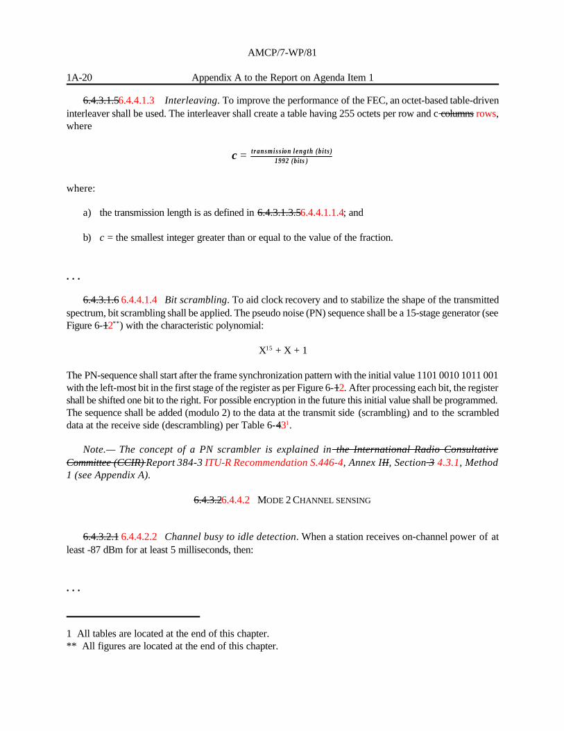
6.4.3.1.56.4.4.1.3 Interleaving. To improve the performance of the FEC, an octet-based table-driveninterleaver shall be used. The interleaver shall create a table having 255 octets per row and c columns rows,where
where:
a) the transmission length is as defined in 6.4.3.1.3.56.4.4.1.1.4; and
b) c = the smallest integer greater than or equal to the value of the fraction.
. . .
6.4.3.1.6 6.4.4.1.4 Bit scrambling. To aid clock recovery and to stabilize the shape of the transmittedspectrum, bit scrambling shall be applied. The pseudo noise (PN) sequence shall be a 15-stage generator (seeFigure 6-12**) with the characteristic polynomial:
X15 + X + 1
The PN-sequence shall start after the frame synchronization pattern with the initial value 1101 0010 1011 001with the left-most bit in the first stage of the register as per Figure 6-12. After processing each bit, the registershall be shifted one bit to the right. For possible encryption in the future this initial value shall be programmed.The sequence shall be added (modulo 2) to the data at the transmit side (scrambling) and to the scrambleddata at the receive side (descrambling) per Table 6-431.
Note.— The concept of a PN scrambler is explained in the International Radio ConsultativeCommittee (CCIR) Report 384-3 ITU-R Recommendation S.446-4, Annex III, Section 3 4.3.1, Method1 (see Appendix A).
6.4.3.26.4.4.2 MODE 2 CHANNEL SENSING
6.4.3.2.1 6.4.4.2.2 Channel busy to idle detection. When a station receives on-channel power of atleast -87 dBm for at least 5 milliseconds, then:
. . .

AMCP/7-WP/81
Appendix A to the Report on Agenda Item 1 1A-21
6.4.3.2.2 6.4.4.2.2.1 Channel idle to busy detection. With a likelihood of at least 0.9, a station shallconsider the channel occupied within 1 millisecond after on-channel power rises to at least -90 dBm.
6.4.3.2.3 6.4.4.2.3 Recommendation.— The detection of an occupied channel should occur within0.5 milliseconds.
Note.— A higher probability of false alarm is acceptable on the idle to busy detection than the busyto idle detection because of the effects of the two different errors.
6.4.3.36.4.4.3 MODE 2 RECEIVER/TRANSMITTER
INTERACTION
6.4.3.3.1 6.4.4.3.1 Receiver to transmitter turnaround time. A station shall begin the transmission ofthe unique word portion of the training sequence within 1 millisecond after terminating the receiver function.The total frequency change during the transmission of the unique word shall be less than 10 Hz. Aftertransmission of the unique word, the phase acceleration shall be less than 500 Hz per second. A station shalltransmit the training sequence such that the center of the first symbol of the unique word will be transmittedwithin 1.25 millisecond after the result of an access attempt is successful (see Figure 6-3). The totalfrequency change during the transmission of the unique word shall be less than 10 Hz. After transmission ofthe unique word, the phase acceleration shall be less than 500 Hz per second.
6.4.3.3.2 6.4.4.3.2 Transmitter to receiver turnaround time. The transmitted power level shall decayat least by 20 dB within 0.3 milliseconds after completing a transmission. A station shall be capable ofreceiving and demodulating with nominal performance, an incoming signal within 1.5 milliseconds aftertransmission of the final information symbol.
6.4.46.4.4.4 MODE 2 PHYSICAL LAYER SYSTEM
PARAMETERS
6.4.4.1 6.4.4.4.1 The physical layer shall implement the system parameters as defined in Table 6-54.
6.4.4.1.16.4.4.4.1.1 Parameter P1 (minimum transmission length). Parameter P1 defines theminimum transmission length that a receiver shall be capable of demodulating without degradation of BER.
Insert new text as follows:
6.4.5 Mode 3 specific physical layer
The Mode 3 specific specification includes a description of Mode 3 management (M) burst and handoff checkmessage (H) burst uplink, M burst downlink, voice/data (V/D) burst, and bit scrambling.

AMCP/7-WP/81
1A-22 Appendix A to the Report on Agenda Item 1
6.4.5.1 Management (M) Burst and Handoff Check Message (H) burst uplink . The M uplink burst(as contained in the Manual on VDL Mode 3 Technical Specifications) shall consist of three segments, theTraining Sequence followed by the System Data and the Transmitter Ramp Down. The H uplink burst (ascontained in the Manual on VDL Mode 3 Technical Specifications) shall consist of three segments, theTraining Sequence followed by the Handoff Check Message and the Transmitter Ramp Down.
6.4.5.1.1 Training sequence. Uplink M burst and H burst training sequences shall consist of twocomponents as follows:
— Transmitter ramp up and power stabilization
— Synchronization and Ambiguity resolution
6.4.5.1.1.1 Transmitter ramp-up and power stabilization. This shall be defined in Section 6.4.4.1.1.1.
6.4.5.1.1.2 Synchronization and ambiguity resolution. The second component of the trainingsequence shall consist of the synchronization sequence-known as S2*-as follows:
000 001 101 100 110 010 111 100 010 011 101 000 111 000 011 001
and shall be transmitted from left to right.
Note.— The sequence S2* is very closely related to the sequence S2 (Section 6.4.2.3.2.3.1.2) . The15 phase changes between the 16 symbols of S2* are each exactly 180o out of phase from the 15 phasechanges associated with S2 . This relationship can be used to simplify the process of simultaneouslysearching for both sequences.
6.4.5.1.2 System Data and Handoff Check Message. The non-3T configuration (as contained in theManual on VDL Mode 3 Technical Specifications) System Data shall consist of 32 transmitted symbols.The 96 transmitted bits shall include 48 bits of information and 48 parity bits, generated as 4 Golay (24, 12)codewords. The 3T configuration as contained in the Manual on VDL Mode 3 Technical Specificationsshall consist of 128 transmitted symbols. The 384 transmitted bits shall include 192 bits of information and 192parity bits, generated as 16 Golay (24, 12) codewords. The 3T configuration handoff check message shallconsist of 40 transmitted symbols. The 120 transmitted bits shall include 60 bits of information and 60 paritybits, generated as 5 Golay (24,12) codewords.
The specific definition of the Golay encoder shall be as follows:
If the 12 bit input bit sequence is written as a row vector x, then the 24 bit output sequence can be writtenas the row vector y, where y = x G, and the matrix G shall be given by
1 1 0 1 0 1 1 1 0 0 0 1 1 0 0 0 0 0 0 0 0 0 0 0
0 1 1 1 1 1 0 0 1 0 0 1 0 1 0 0 0 0 0 0 0 0 0 0
1 1 1 0 1 0 0 1 0 1 0 1 0 0 1 0 0 0 0 0 0 0 0 0

AMCP/7-WP/81
Appendix A to the Report on Agenda Item 1 1A-23
0 1 1 0 0 0 1 1 1 0 1 1 0 0 0 1 0 0 0 0 0 0 0 0
1 1 1 0 0 1 1 0 1 1 0 0 0 0 0 0 1 0 0 0 0 0 0 0
G = 1 0 1 1 0 0 1 1 0 1 1 0 0 0 0 0 0 1 0 0 0 0 0 0
1 0 0 1 1 0 0 1 1 0 1 1 0 0 0 0 0 0 1 0 0 0 0 0
0 1 0 1 1 0 1 1 1 1 0 0 0 0 0 0 0 0 0 1 0 0 0 0
0 0 1 0 1 1 0 1 1 1 1 0 0 0 0 0 0 0 0 0 1 0 0 0
0 0 0 1 0 1 1 0 1 1 1 1 0 0 0 0 0 0 0 0 0 1 0 0
1 1 0 1 1 1 0 0 0 1 1 0 0 0 0 0 0 0 0 0 0 0 1 0
1 0 1 0 1 1 1 0 0 0 1 1 0 0 0 0 0 0 0 0 0 0 0 1
Note.— The extended Golay code allows for the correction of any error pattern with 3 or fewerbit errors and the detection of any 4-bit error pattern.
6.4.5.1.3 Transmitter ramp-down. Following the end of the final symbol, the transmitter power shallbe below -20 dBc within 2 symbol periods. The transmitter power leakage when the transmitter is in the “off”state shall be less than -83 dBm.
Note.— Reference RTCA/DO-160D section 21, category H for antenna radiated signals.
6.4.5.2 Management (M) burst downlink . The M downlink burst (as contained in the Manual on VDLMode 3 Technical Specifications) shall consist of three segments, the Training Sequence followed by theSystem Data and the Transmitter Ramp Down.
6.4.5.2.1 Training sequence. The M downlink burst training sequence shall consist of two componentsas follows:
— Transmitter ramp up and power stabilization
— Synchronization and Ambiguity resolution
6.4.5.2.1.1 Transmitter ramp-up and power stabilization. This shall be as defined inSection 6.4.5.1.1.1.
6.4.5.2.1.2 Synchronization and ambiguity resolution. Three separate synchronization sequencesshall be used for this burst type. The standard sequence - known as S1 - shall be as follows:
000 111 001 001 010 110 000 011 100 110 011 111 010 101 100 101
and shall be transmitted from left to right. The special sequence used to identify poll responses shall be asdefined in Section 6.4.5.1.1.2.

AMCP/7-WP/81
1A-24 Appendix A to the Report on Agenda Item 1
The special sequence used to identify Net Entry Requests (S1*) shall use the following sequence:
000 001 111 111 100 000 110 101 010 000 101 001 100 011 010 011
and shall be transmitted from left to right.
Note.— The sequence S1* is very closely related to the sequence S1. The 15 phase changes betweenthe 16 symbols of S1* are each exactly 180o out of phase from the 15 phase changes associated withS1 . This relationship can be used to simplify the process of simultaneously searching for bothsequences.
6.4.5.2.2 System data. The System Data segment shall consist of 16 transmitted symbols. The 48transmitted bits shall be encoded as 24 bits of System Data and 24 bits of parity bits generated as twoconsecutive (24, 12) Golay code words. The encoding of the (24, 12) Golay code words should be as definedin Section 6.4.5.1.2.
6.4.5.2.3 Transmitter ramp-down. This shall be as defined in Section 6.4.5.1.3.
6.4.5.3 Voice or data (V/D) burst. The V/D burst (as contained in the Manual on VDL Mode 3Technical Specifications) shall consist of four segments: the Training Sequence followed by the Header, theUser Information segment and the Transmitter Ramp Down. The same V/D burst format shall be used forboth uplink and downlink.
6.4.5.3.1 Training sequence. V/D burst training sequence shall consist of two components as follows:
— Transmitter ramp-up and power stabilization
— Synchronization and Ambiguity resolution
6.4.5.3.1.1 Transmitter ramp-up and power stabilization. This shall be as specified inSection 6.4.5.1.1.1.
6.4.5.3.1.2 Synchronization and ambiguity resolution. The second component of the trainingsequence shall consist of the synchronization sequence-known as S2-as follows:
000 111 011 010 000 100 001 010 100 101 011 110 001 110 101 111
and shall be transmitted from left to right.
6.4.5.3.2 Header. The Header segment shall consist of 8 transmitted symbols. The 24 transmitted bitsshall be encoded as 12 bits of Header information and 12 parity bits, generated as a single (24, 12) Golay codeword. The encoding of the (24, 12) Golay code word shall be as defined in Section 6.4.5.1.2.
6.4.5.3.3 User information. The User Information segment shall consist of 192 3-bit symbols. Whentransmitting voice, FEC shall be applied to the analysis output of the vocoder specified in Section 6.8. The

AMCP/7-WP/81
Appendix A to the Report on Agenda Item 1 1A-25
i=120
129i(x - )∏ α
vocoder shall provide satisfactory performance in a BER environment of 10-3 (with a design goal of 10-2). Theoverall bit rate of the vocoder including FEC is 4800 bps (except when in the truncated mode in which thebit rate is 4000 bps).
When transmitting user data, the 576 bits shall be encoded as a single Reed-Solomon (72, 62) 28-ary codeword. For user data input to the Reed-Solomon encoder of length less than 496 bits, input data shall be paddedwith zeroes at the end to a full length of 496 bits. The field defining the primitive polynomial of the code shallbe as described in Section 6.4.3.3.1.3.1. The generator polynomial shall be as follows:
Note.— The Reed-Solomon (72, 62) code is capable of correcting up to five 28-ary (code word)symbol errors in the received word.
6.4.5.3.4 Transmitter ramp-down. This shall be as defined in Section 6.4.5.1.3.
6.4.5.4 Interleaving. There shall be no interleaving in Mode 3 operation.
6.4.5.5 Bit scrambling. Under Mode 3 operation, bit scrambling, as specified in Section 6.4.4.1.4 shallbe performed on each burst, starting after the training sequence. The scrambling sequence shall bereinitialized on each burst effectively providing a constant overlay for each of the Mode 3 fixed length bursts.
6.4.5.6 Receiver/transmitter interaction
The switching times in this subsection will be defined as the time between the middle of the last informationsymbol of one burst and the middle of the first symbol of the synchronization sequence of the subsequentburst.
Note.— This nominal time will be shortened by considerations such as the finite width of eachsymbol due to Nyquist filtering and the ramp up and power stabilization sequence. Such alternativedefinitions could yield switching times up to 8 symbol periods shorter.
6.4.5.6.1 Receiver to transmitter switching time. An aircraft radio shall be capable of switching fromreception to transmission within 17 symbol periods. This time can be relaxed to 33 symbol periods for aircraftradios which do not implement functions requiring discrete addressing.
Note 1.— The shortest R/T switching time for an aircraft radio occurs when the reception of anuplink M channel beacon is followed by a V/D transmission in the same slot. In certain instances whereaircraft radios do not implement functions requiring discrete addressing, the R/T switching time canbe increased since the last two Golay words of the uplink M channel beacon need not be read.
Note 2.— The minimum turnaround time assumes that in configurations 3V1D, 2V1D, and 3T (ascontained in Section 5.5.2.4 of the Manual on VDL Mode 3 Technical Specifications), the aircraft

AMCP/7-WP/81
1A-26 Appendix A to the Report on Agenda Item 1
radios will be provided with software that will prevent them from transmitting a downlink M channelmessage in a slot following the reception of a voice message from another aircraft with a long timedelay.
6.4.5.6.2 Transmitter to receiver switching time. An aircraft radio shall be capable of switching fromtransmission to reception within 32 symbol periods.
Note.— The worst case T/R switching time for an aircraft radio occurs when it transmits a downlinkM channel message and receives a V/D message in the same slot.
6.4.5.7 Fringe coverage indication.
6.4.5.7.1 Recommendation.— Indication of near edge-of-coverage should be provided to theVDL Mode 3 aircraft.
End of new text.
6.5 LINK LAYER PROTOCOLSAND SERVICES
6.5.1 General information
6.5.1.1 Functionality. The VHF digital link (VDL) link layer shall provide the following sub-layerfunctions:
a) media access control (MAC) sub-layer, which requires the use of the carrier sense multiple access(CSMA) algorithm for Mode 2 or TDMA for Mode 3;
b) a data link service (DLS) sub-layer
— For Mode 2, the DLS sub-layer , providing provides connection-oriented point-to-point linksusing data link entities (DLE) and connection-less broadcast link over the MAC sub-layer
— For Mode 3, the DLS sub-layer provides acknowledged connectionless point-to-point andpoint-to-multipoint links over a MAC sublayer that guarantees sequencing; and
c) a VDL management entity (VME), which establishes and maintains DLEs between the aircraft andthe ground-based systems using link management entities (LME).
6.5.1.2 SERVICE

AMCP/7-WP/81
Appendix A to the Report on Agenda Item 1 1A-27
6.5.1.2.1 Connection-oriented. The VDL Mode 2 link layer shall provide a reliable point-to-pointservice using a connection-oriented DLS sub-layer.
6.5.1.2.2 Connection-less . The VDL Mode 2 and 3link layers shall provide an unacknowledgedbroadcast service using a connection-less DLS sub-layer.
6.5.1.2.3 Acknowledged Connection-less. The VDL Mode 3 link layer shall provide an acknowledgedpoint-to-point service using a connectionless DLS sublayer that relies upon the MAC sublayer to guaranteesequencing.
6.5.2 MAC sub-layer
6.5.2.1 The MAC sub-layer shall provide for the transparent acquisition of the shared communicationspath. It makes invisible to the DLS sub-layer the way in which supporting communications resources areutilized to achieve this.
Note.— Specific MAC services and procedures for VDL Modes 2 and 3 are contained in theManuals on VDL Mode 2 and VDL Mode 3 Technical Specifications.
Note.— The service specification for the MAC sub-layer is modeled on the MAC Service Definition(ISO DP 10039).
Editorial Note.— Delete Sections 6.5.2.2 to 6.5.2.4 in their entirety.
6.5.3 Data link service sub-layer
6.5.3.1 For Mode 2, Tthe DLS shall support bit-oriented simplex air-ground communications using theaviation VHF link control (AVLC) protocol specified in this section.
Note.— Specific data link services, parameters, and protocol definitions for VDL Mode 2 arecontained in the Manual on VDL Mode 2 Technical Specifications.
Note.— The DLS is derived from HDLC, as specified by ISO 3309, ISO 4335, ISO 7809, and ISO8885. Any definitions of service are derived from the OSI Data Link Service Definition ISO 8886.3.AVLC is a variant of HDLC and derived from, but is not fully specified by, options 1, 3.2, 4, 7, and 12of ISO 7809. Explicit references to these documents are made later in this section.
6.5.3.2 For Mode 3, the DLS shall support bit-oriented, priority based, simplex air-groundcommunications using the acknowledged connectionless data link (A-CLDL) protocol.
Note.— Specific data link services, parameter, and protocol definitions for VDL Mode 3 are containedin the Manual on VDL Mode 3 Technical Specifications.

AMCP/7-WP/81
1A-28 Appendix A to the Report on Agenda Item 1
Editorial Note.— Delete Sections 6.5.3.2, 6.5.3.3, 6.5.3.4, 6.5.3.5, 6.5.3.6, 6.5.3.7, 6.5.3.8, 6.5.3.9,6.5.3.10 and 6.5.3.11 in their entirety.
6.5.4 VDL management entity
6.5.4.1 Services. The VME shall provide link establishment, maintenance and disconnection servicesas well as support parameter modification. Specific VME services, parameter formats, and procedures forModes 2 and 3 are contained in the Manuals on VDL Mode 2 and Mode 3 Technical Specifications.
Editorial Note.— Delete Sections 6.5.4.1, 6.5.4.2, 6.5.4.3 and 6.5.4.4 in their entirety.
6.6 SUBNETWORK LAYERPROTOCOLS AND SERVICES
6.6.1 Architecture for Mode 2
6.6.1.1 The subnetwork layer protocol used across the VHF air-ground subnetwork for VDL Mode 2is referred to formally as a subnetwork access protocol (SNAcP) and shall conform to ISO 8208, except asnoted belowcontained in the Manual on VDL Mode 2 Technical Specifications. The SNAcP is containedreferred to within this document the Manual on VDL Mode 2 Technical Specifications as the subnetworkprotocol. If there are any differences between this documentthe Manual on VDL Mode 2 TechnicalSpecifications and the cited specifications, this documentthe Manual on VDL Mode 2 Technical Specificationsshall have precedence. On the air-ground interface, the aircraft subnetwork entity shall act as a DTE and theground subnetwork entity shall act as a DCE.
Note.— Specific subnetwork layer protocol access points, services, packet formats, parameters andprocedures for VDL Mode 2 are contained in the Manual on VDL Mode 2 Technical Specifications.
6.6.1.1 Access points. The subnetwork service access point (SNSAP) shall be uniquely identified bythe subnetwork data terminal equipment (DTE) address. SNSAPs shall define the subnetwork point ofattachment (SNPA) used by the service primitives that define the subnetwork service to the subnetworkdependence convergence protocol.
6.6.2 Architecture for Mode 3
6.6.2.1 The subnetwork layer used across the VHF air-ground subnetwork for VDL Mode 3 providesthe flexibility to simultaneously support multiple subnetwork protocols. The currently defined options are tosupport ISO8473 Connectionless Network Protocol and to support ISO8208, both as contained in the Manualon VDL Mode 3 Technical Specifications. The Manual on VDL Mode 3 Technical Specifications shall haveprecedence with respect to any differences with the cited specifications. For the ISO8208 interface, both theair and ground subnetwork entities shall act as DCEs.

AMCP/7-WP/81
Appendix A to the Report on Agenda Item 1 1A-29
Note.— Specific subnetwork layer protocol access points, services, packet formats, parameters andprocedures for VDL Mode 3 are contained in the Manual on VDL Mode 3 Technical Specifications.
Editorial Note.— Delete Sections 6.6.2, 6.6.3, 6.6.4, 6.6.5 and 6.6.6 in their entirety.
6.7 THE VDL MOBILESUBNETWORK DEPENDENT
CONVERGENCE FUNCTION (SNDCF)
6.7.1 VDL Mode 2 SNDCF
6.7.1.1 Introduction. The VDL Mode 2 mobile SNDCF shall be the standard mobile SNDCF.
6.7.1.2 New function. The VDL Mode 2 mobile SNDCF shall support maintaining context(e.g. compression tables) across subnetwork calls. The SNDCF shall use the same context (e.g. compressiontables) across all SVCs negotiated to a DTE, when negotiated with the same parameters. The SNDCF shallsupport at least 2 SVCs sharing a context.
Note.— Because handoffs can be expected to reorder packets, certain compression algorithms donot lend themselves to use over the VDL Mode 2. Further, implementors of dictionary-basedcompression algorithms must be sensitive to the problem of updates arriving on either the old or newlyestablished call.
6.7.1.3 Call user data encodingNote.— The encoding of the Call User Data field shall be asdetailed is described in the ATN Manual Manual of Technical Provisions for the AeronauticalTelecommunication Network (ATN) (Doc 9705), except as modified below with modifications ascontained in the Manual on VDL Mode 2 Technical Specifications.
Editorial Note.— Delete existing Sections 6.7.3.1 to 6.7.3.4
Insert new text as follows:
6.7.2 VDL Mode 3 SNDCF
6.7.2.1 The VDL Mode 3 shall support one or more of the defined SNDCFs. The first is the standardISO 8208 SNDCF as defined in the Manual of Technical Provisions for the AeronauticalTelecommunication Network (ATN) (Doc 9705). This is a connection oriented SNDCF. The second typeof SNDCF supported by VDL Mode 3 is denoted frame-based SNDCF. The details of this connection-lessoriented SNDCF are contained in the Manual on VDL Mode 3 Technical Specifications, including networklayer interface, support for broadcast and unicast network packets, and ATN router support.

AMCP/7-WP/81
1A-30 Appendix A to the Report on Agenda Item 1
Note.— The framed-based SNDCF is termed such because it uses the VDL Mode 3 frames withoutthe need for an additional protocol (viz. ISO 8208 SNDCF) to transfer network packets. Theframe-based SNDCF achieves independence from the network protocol by identifying the payload ofeach frame. Upon receipt of a frame, the payload is examined and control is passed to the protocolidentified.
6.8 VOICE UNIT FOR MODE 3
6.8.1 Services
6.8.1.1 The Voice Unit shall provide for a simplex, “push-to-talk” audio and signalling interface betweenthe user and the VDL. Two separate mutually exclusive voice circuit types shall be supported.
— Dedicated circuits: This shall provide service to a specific user group on an exclusive basis with nosharing of the circuit with other users outside the group. Access shall be based on a“listen-before-push-to-talk” discipline.
— Demand assigned circuits: This shall provide voice circuit access which is arbitrated by the groundstation in response to an access request received from the aircraft station. This type of operation shallallow dynamic sharing of the channel resource increasing trunking efficiency.
6.8.1.2 Priority Access. The Voice Unit operation shall support a priority override access forauthorized ground users.
6.8.1.3 Message Source Identification. The Voice Unit operation shall support notification to the userof the source of a received message (i.e., whether the message originated from an air or ground station).
6.8.1.4 Coded Squelch. The Voice Unit shall support a coded squelch operation that offers somedegree of rejection of undesired cochannel voice messages based on the burst time of arrival.
6.8.2 Speech encoding, parameters, and procedures
6.8.2.1 The VDL Mode 3 shall use the Augmented Multiband Excitation (AMBE) 4.8 kbpsencoding/decoding algorithm, version number AMBE-ATC-10, developed by Digital Voice Systems,Incorporated (DVSI) for voice communications.
Note 1.— Information on technical characteristics of the 4.8 kbits/s AMBE algorithm is containedin AMBE-ATC-10 Low Level Description, obtainable from DVSI.
Note 2.— The 4.8 kbits/s AMBE encoding/decoding technology described in the document issubject to DVSI patent rights and copyrights. Manufacturers must enter into a license agreement withDVSI prior to obtaining a detailed description of the algorithm before incorporation in equipment

AMCP/7-WP/81
Appendix A to the Report on Agenda Item 1 1A-31
operating in the VDL Mode 3 service. By letter to ICAO dated 29 October 1999, DVSI confirmed itscommitment to license the technology for the manufacture and sale of aeronautical equipment underreasonable terms and conditions, negotiated on a non-discriminatory basis.
6.8.2.2 Speech encoding definition, voice unit parameters, and procedure descriptions for VDL Mode3 Voice Unit operation are contained in the Manual on VDL Mode 3 Technical Specifications.
6.9 VDL MODE 4
6.9.1 A Mode 4 station shall conform to the requirements defined in sections 6.1.4.2, 6.2.1.1, 6.2.3.1,6.2.4, 6.3.1, 6.3.3.1, 6.3.4, 6.3.5.2, 6.3.5.3, 6.3.5.4 and 6.9.
6.9.2 VDL Mode 4 radio channels
6.9.2.1 VDL MODE 4 STATION FREQUENCY RANGE
6.9.2.1.1 Transmitter/receiver tuning range. A VDL Mode 4 transmitter/receiver shall be capableof tuning to any of the 25 kHz channels from 117.975 MHz through 137 MHz. The transmitter shall have ameans for the tuning range to be restricted to a narrower range.
Note.— Operational conditions or certain applications may require the equipment to be operatedin a narrower frequency range.
6.9.2.1.2 Recommendation.— A VDL Mode 4 transmitter/receiver should be capable of tuningto any of the 25 kHz channels from 108 to 117.975 MHz.
Note.— The band 108 - 117.975 MHz may be utilized in some States for ADS applications.
6.9.2.1.3 Simultaneous reception. A VDL Mode 4 station shall be capable of receiving two channelssimultaneously.
6.9.2.1.4 Recommendation.— A VDL Mode 4 station should be capable of receiving additionalchannels simultaneously as required by operational services.
6.9.2.2 GLOBAL SIGNALLING CHANNELS
6.9.2.2.1 VDL Mode 4 stations shall use two assigned frequencies as global signalling channels (GSC),to support user communications and link management functions.
Note.— Additional channels may be defined in a local domain, and notified to mobile users bybroadcast from ground stations on the GSCs defined above.
6.9.3 System capabilities

AMCP/7-WP/81
1A-32 Appendix A to the Report on Agenda Item 1
6.9.3.1 ATN compatibility. The VDL Mode 4 system shall support ATN-compliant subnetworkservices for surveillance applications.
6.9.3.2 Data transparency. The VDL Mode 4 system shall provide code-independent,byte-independent transfer of data.
6.9.3.3 Broadcast. The VDL Mode 4 system shall provide link layer broadcast services.
6.9.3.4 Point to point. The VDL Mode 4 system shall provide link layer point to point services.
6.9.3.5 Air-air communications. The VDL Mode 4 system shall provide air-air communications,without ground support, as well as air-ground communications.
6.9.3.6 Connection management. When supporting air-ground operations, the VDL Mode 4 systemshall establish and maintain a reliable communications path between the aircraft and the ground system whileallowing, but not requiring, manual intervention.
6.9.3.7 Ground network transition. A mobile VDL Mode 4 DLS station shall transition from oneground VDL Mode 4 DLS station to another as required.
6.9.3.8 Derived time capability. VDL Mode 4 shall provide the capability for deriving time fromtime-of-arrival measurements of received VDL Mode 4 transmissions whenever externally derived estimatesof time are unavailable.
6.9.3.9 Simplex operations. Mobile and ground VDL Mode 4 stations shall access the physical mediumoperating in simplex mode.
6.9.4 Coordination of channel utilization
6.9.4.1 On a regional basis, transmissions shall be scheduled relative to UTC, to ensure efficient useof shared channels and to avoid unintentional slot re-use.
6.9.5 Physical layer protocols and services
Note.— Unless otherwise stated, the requirements defined in this section apply to both mobile andground stations.
6.9.5.1 FUNCTIONS
6.9.5.1.1 TRANSMITTED POWER

AMCP/7-WP/81
Appendix A to the Report on Agenda Item 1 1A-33
6.9.5.1.1.1 Airborne installation. On a high percentage of occasions, the effective radiated powershall be such as to provide a field strength of at least 35 microvolts per metre (minus 114.5 dBW/m2) on thebasis of free space propagation, at ranges and altitudes appropriate to the conditions pertaining to the areasover which the aircraft is operated.
6.9.5.1.1.2 Ground installation.
Recommendation.— The effective radiated power should be such as to provide a field strengthof at least 75 microvolts per metre (minus 109 dBW/m2) within the defined operational coverage of thefacility, on the basis of free-space propagation.
6.9.5.1.2 TRANSMITTER AND RECEIVER FREQUENCY CONTROL
6.9.5.1.2.1 The VDL Mode 4 physical layer shall set the transmitter or receiver frequency ascommanded by the link management entity (LME). Channel selection time shall be less than 13 ms after thereceipt of a command from a VSS user.
6.9.5.1.3 DATA RECEPTION BY RECEIVER
6.9.5.1.3.1 The receiver shall decode input signals and forward them to the higher layers for processing.
6.9.5.1.4 DATA TRANSMISSION BY TRANSMITTER
6.9.5.1.4.1 Data encoding and transmission. The physical layer shall encode the data received fromthe data link layer and transmit it over the RF channel. RF transmission shall take place only when permittedby the MAC.
6.9.5.1.4.2 Order of transmission. The transmission shall consist of the following stages in thefollowing order:
a) transmitter power stabilization;
b) bit synchronization;
c) ambiguity resolution and data transmission; and
d) transmitter decay.
Note.— The definitions of the stages are given in sections 6.9.5.2.3.1 to 6.9.5.2.3.4.

AMCP/7-WP/81
1A-34 Appendix A to the Report on Agenda Item 1
6.9.5.1.4.3 Automatic transmitter shutdown. A VDL Mode 4 station shall automatically shut-downpower to any final stage amplifier in the event that output power from that amplifier exceeds -30 dBm formore than 1 second. Reset to an operational mode for the affected amplifier shall require a manual operation.
Note.— This is intended to protect the shared channel resource against so-called “stucktransmitters”.
6.9.5.1.5 NOTIFICATION SERVICES
6.9.5.1.5.1 Signal quality. The operational parameters of the equipment shall be monitored at thephysical layer. Signal quality analysis shall be performed in the demodulator process and in the receiveprocess.
Note.— Processes that may be evaluated in the demodulator include bit error rate (BER), signalto noise ratio (SNR), and timing jitter. Processes that may be evaluated in the receiver include receivedsignal level and group delay.
6.9.5.1.5.2 Arrival time. The arrival time of each received transmission shall be measured with atwo-sigma error of 5 microseconds.
6.9.5.1.5.3 Recommendation.— The receiver should be capable of measuring the arrival timewithin a two-sigma error of 1 microsecond.
6.9.5.2 PROTOCOL DEFINITION FOR GFSK
6.9.5.2.1 Modulation scheme. The modulation scheme shall be GFSK. The first bit transmitted (in thetraining sequence) shall be a high tone and the transmitted tone shall be toggled before transmitting a 0(i.e. non-return to zero inverted encoding).
6.9.5.2.2 Modulation rate. Binary ones and binary zeros shall be generated with a modulation indexof 0.25 ± 0.03 and a BT product of 0.28 ± 0.03, producing data transmission at a bit rate of 19,200 bits/sec± 50 ppm.

AMCP/7-WP/81
Appendix A to the Report on Agenda Item 1 1A-35
6.9.5.2.3 STAGES OF TRANSMISSION
6.9.5.2.3.1 Transmitter power stabilization. The first segment of the training sequence is thetransmitter power stabilization, which shall have a duration of 16 symbol periods. The transmitter power levelshall be no less than 90% of the steady state power level at the end of the transmitter power stabilizationsegment.

AMCP/7-WP/81
1A-36 Appendix A to the Report on Agenda Item 1
6.9.5.2.3.2 Bit synchronization. The second segment of the training sequence shall be the 24-bit binarysequence 0101 0101 0101 0101 0101 0101, transmitted from left to right immediately before the start of thedata segment.
6.9.5.2.3.3 Ambiguity resolution and data transmission. The transmission of the first bit of data shallstart 40 bit intervals (approximately 2083.3 microsecond) ± 1 microsecond after the nominal start oftransmission.
Note 1.— This is referenced to emissions at the output of the antenna.
Note 2.— Ambiguity resolution is performed by the link layer.
6.9.5.2.3.4 Transmitter decay. The transmitted power level shall decay at least by 20 dB within 300microsecond after completing a transmission. The transmitter power level shall be less than -90 dBm within832 microsecond after completing a transmission.
6.9.5.3 CHANNEL SENSING
6.9.5.3.1 Estimation of noise floor. A VDL Mode 4 station shall estimate the noise floor based onpower measurements of the channel whenever a valid training sequence has not been detected.
6.9.5.3.2 The algorithm used to estimate the noise floor shall be such that the estimated noise floor shallbe lower than the maximum power value measured on the channel over the last minute when the channel isregarded as idle.
Note.— The VDL Mode 4 receiver uses an energy sensing algorithm as one of the means todetermine the state of the channel (idle or busy). One algorithm that can be used to estimate the noisefloor is described in the Manual on VDL Mode 4 Technical Specifications.
6.9.5.3.3 Channel idle to busy detection. A VDL Mode 4 station shall employ the following meansto determine the channel idle to busy transition at the physical layer.
6.9.5.3.3.1 Detection of a training sequence. The channel shall be declared busy if a VDL Mode 4station detects a valid training sequence followed by a frame flag.
6.9.5.3.3.2 Measurement of channel power. Regardless of the ability of the demodulator to detecta valid training sequence, a VDL Mode 4 station shall consider the channel busy with at least a 95%probability within 1 ms after on-channel power rises to the equivalent of at least four times the estimated noisefloor for at least 0.5 milliseconds.

AMCP/7-WP/81
Appendix A to the Report on Agenda Item 1 1A-37
6.9.5.3.4 Channel busy to idle detection
6.9.5.3.4.1 A VDL Mode 4 station shall employ the following means to determine the channel busy toidle transition.
6.9.5.3.4.2 Measurement of transmission length. When the training sequence has been detected, thechannel busy state shall be held for a period of time at least equal to 5 millisecond, and subsequently allowedto transition to the idle state based on measurement of channel power.
6.9.5.3.4.3 Measurement of channel power. When not otherwise held in the channel busy state, aVDL Mode 4 station shall consider the channel idle with at least a 95% probability if on-channel power fallsbelow the equivalent of twice the estimated noise floor for at least 0.9 millisecond.
6.9.5.4 RECEIVER/TRANSMITTER INTERACTION
6.9.5.4.1 Receiver to transmitter turnaround time. A VDL Mode 4 station shall be capable ofbeginning the transmission of the transmitter power stabilization sequence within 16 microseconds afterterminating the receiver function.
6.9.5.4.2 Frequency change during transmission. The phase acceleration of the carrier from the startof the synchronization sequence to the data end flag shall be less than 300 Hz per second.
6.9.5.4.3 Transmitter to receiver turnaround time. A VDL Mode 4 station shall be capable ofreceiving and demodulating with nominal performance an incoming signal within 1 ms after completing atransmission.
Note.— Nominal performance is defined as a BER of 10-4.
6.9.5.5 PHYSICAL LAYER SYSTEM PARAMETERS
6.9.5.5.1 Parameter P1 (minimum transmission length)
6.9.5.5.1.1 The parameter P1 shall be the minimum transmission length that a receiver shall be capableof demodulating without degradation of BER.
6.9.5.5.1.2 The value of P1 shall be 19 200 bits.
6.9.5.5.2 Parameter P2 (nominal co-channel interference performance)
6.9.5.5.2.1 The parameter P2 shall be the nominal co-channel interference at which a receiver shallbe capable of demodulating without degradation in BER for a desired signal which arrives prior to aninterfering signal.

AMCP/7-WP/81
1A-38 Appendix A to the Report on Agenda Item 1
6.9.5.5.2.2 The value of P2 shall be 12 dB.
6.9.6 Link layer
Note.— Details on link layer functions are contained in the Manual on VDL Mode 4 TechnicalSpecifications.
6.9.7 Subnetwork layer
Note.— Details on subnetwork layer functions are contained in the Manual on VDL Mode 4Technical Specifications.
6.9.8 ADS-B applications
Note.— Details on ADS-B application functions are contained in the Manual on VDL Mode 4Technical Specifications.
End of new text.
TABLES FOR CHAPTER 6
Table 6-1. Mode s 2 and 3 data encoding
Xk Yk Zk ªö k
0 0 0 0 ð / 40 0 1 1 ð / 40 1 1 2 ð / 40 1 0 3 ð / 41 1 0 4 ð / 41 1 1 5 ð / 41 0 1 6 ð / 41 0 0 7 ð / 4

AMCP/7-WP/81
Appendix A to the Report on Agenda Item 1 1A-39
Table 6-2. Spectral mask of transmitter for D8PSK
LOWER BOUND UPPER BOUNDFrequencyDeviation
Attenuation FrequencyDeviation
Attenuation
0 -0.25 0 0.251700 -0.25 2500 0.253000 -1 3900 -13900 -3 4900 -34800 -6 5800 -65350 -10 6650 -106310 -20 7910 -206680 -30 8680 -30
Note.— Frequency deviation from the channel centre (on both sides) isspecified in Hz, and the attenuation is specified in dBc.
Table 6-3. Tolerance on the phase mask of transmitter for D8PSK
LOWER BOUND UPPER BOUNDFrequencyDeviation
Phase Frequencydeviation
Phase
0 -1.8 0 1.85250 -1.8 5250 1.85250 -2.8 5250 2.86000 -2.8 6000 2.86000 -180 6000 180
Note.— Frequency deviation from the channel centre (on both sides) isspecified in Hz, and the phase is specified in degrees deviation from linear.
Table 6-2. Modes 2 and 3 Modulation Stability
VDL Mode AircraftModulation
Stability
GroundModulation
Stability
Mode 2 ± 0.0050 percent ± 0.0050 percentMode 3 ± 0.0005 percent ± 0.0002 percent

AMCP/7-WP/81
1A-40 Appendix A to the Report on Agenda Item 1
–5.5
Center of first symbol of unique word.
Power at 90%by t = -3
Major divisions aresymbol periods.
–5 –4 -3 -2 -1 0
Figure 6-1. Transmitter Power Stabilization
Table 6-43. Scrambler functions
Function Data in Data out
Scrambling clean data scrambled dataDescrambling Scrambled data clean data
Table 6-54. Physical services system parameters
Symbol Parameter name Mode 1 value Mode 2 value
P1 Minimum transmission length 16504 bits 131071 bits
. . .
Insert new figure as follows:
End of new figure.
. . .
Delete existing Figure 6-2:Figure 6-2. Link layer frame format
Figure 6-16-2. PN-generator for bit scrambling sequence

AMCP/7-WP/81
Appendix A to the Report on Agenda Item 1 1A-41
1.5msec
1.25msec
90%power, corresponds to time -3inFigure 6-1 above.
Currentreceptioncompletes
Accessattemptoccurs
Figure 6-3. Receive to Transmit Turnaround Time
Insert new figure as follows:
End of new figure.
— — — — — — — —