AP32275 - XMC1000 - Brightness and Color Control Unit(BCCU)
42
Application Note Please read the Important notice and warnings at the end of this document Revision 1.1 www.infineon.com 2015-12-01 AP32275 Brightness and Color Control Unit (BCCU) XMC1000 About this document Scope and purpose This document provides a brief introduction to the key features of the Brightness and Color Control Unit (BCCU) for the XMC1000 Microcontroller family. The document includes some typical LED lighting application examples and hints on how to best use the BCCU. Intended audience This document is intended for engineers who wish to develop an LED lighting application with the XMC1000 microcontroller. Applicable products XMC1200 XMC1202 XMC1302 XMC1402 XMC1404 DAVE ™ LED lighting application kit References Infineon: DAVE™, http://www.infineon.com/DAVE Infineon: XMC™ Family, http://www.infineon.com/XMC
Transcript of AP32275 - XMC1000 - Brightness and Color Control Unit(BCCU)
Application Note Please read the Important notice and warnings at the end of this document Revision 1.1
www.infineon.com 2015-12-01
AP32275
Brightness and Color Control Unit (BCCU)
XMC1000
About this document
Scope and purpose
This document provides a brief introduction to the key features of the Brightness and Color Control Unit (BCCU) for the XMC1000 Microcontroller family. The document includes some typical LED lighting application examples and hints on how to best use the BCCU.
Intended audience
This document is intended for engineers who wish to develop an LED lighting application with the XMC1000 microcontroller.
Applicable products
XMC1200
XMC1202
XMC1302
XMC1402
XMC1404
DAVE ™
LED lighting application kit
References
Infineon: DAVE™, http://www.infineon.com/DAVE
Infineon: XMC™ Family, http://www.infineon.com/XMC

Application Note 2 Revision 1.1
2015-12-01
Brightness and Color Control Unit (BCCU) XMC1000
Brightness and Color Control Unit basics
Table of contents
About this document ............................................................................................................................................. 1
Table of contents ................................................................................................................................................... 2
1 Brightness and Color Control Unit basics ........................................................................................... 3 1.1 Introduction to modulation dimming .................................................................................................... 3 1.2 Channels .................................................................................................................................................. 4 1.2.1 Linear walker ...................................................................................................................................... 5
1.2.2 Sigma-delta modulator ...................................................................................................................... 8
1.2.3 Packer ................................................................................................................................................. 8 1.3 Dimming engines ..................................................................................................................................... 9 1.3.1 Exponential dimming ......................................................................................................................... 9 1.3.2 Dither function ................................................................................................................................. 11
1.4 Typical application examples ............................................................................................................... 12 1.4.1 Multichannel lamps .......................................................................................................................... 12
1.4.2 Simple digital-to-analog converter (DAC) ....................................................................................... 15
2 Color LED lamp control with BCCU .................................................................................................. 16 2.1 Color LED lamp ...................................................................................................................................... 16
2.2 BCCU for color LED lamps ..................................................................................................................... 16 2.2.1 Controlling lamp color ..................................................................................................................... 18 2.3 RGB LED example .................................................................................................................................. 21
2.3.1 Implementation with XMC™ Lib ....................................................................................................... 23
2.3.2 Implementation with DAVETM APPs.................................................................................................. 27
2.3.2.1 Controlling lamp color ................................................................................................................ 29
3 Exponential dimming with BCCU ..................................................................................................... 32
3.1 Dimming engine .................................................................................................................................... 32
3.2 RGB LED example revisited ................................................................................................................... 36
3.2.1 Implementation with XMC™ Lib ....................................................................................................... 36 3.2.2 Implementation with DAVETM APPs.................................................................................................. 38
3.2.2.1 Controlling lamp brightness ....................................................................................................... 39
Revision history ................................................................................................................................................... 41
Application Note 3 Revision 1.1
2015-12-01
Brightness and Color Control Unit (BCCU) XMC1000
Brightness and Color Control Unit basics
1 Brightness and Color Control Unit basics
This section provides an overview of the key concepts for using the Brightness and Color Control Unit (BCCU).
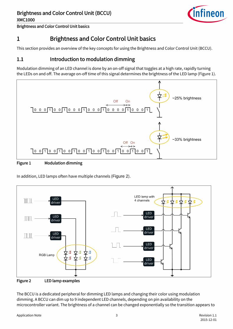
1.1 Introduction to modulation dimming
Modulation dimming of an LED channel is done by an on-off signal that toggles at a high rate, rapidly turning the LEDs on and off. The average on-off time of this signal determines the brightness of the LED lamp (Figure 1).
Figure 1 Modulation dimming
In addition, LED lamps often have multiple channels (Figure 2).
Figure 2 LED lamp examples
The BCCU is a dedicated peripheral for dimming LED lamps and changing their color using modulation
dimming. A BCCU can dim up to 9 independent LED channels, depending on pin availability on the microcontroller variant. The brightness of a channel can be changed exponentially so the transition appears to

Application Note 4 Revision 1.1
2015-12-01
Brightness and Color Control Unit (BCCU) XMC1000
Brightness and Color Control Unit basics
be even to the human eye. A BCCU contains 9 channels, 3 dimming engines (DE) and a connection matrix that links them to each other (Figure 3).
Figure 3 BCCU block diagram
The DEs generate the dimming levels. The channels generate the intensity levels. These two levels, each with a
12-bit resolution, are combined in the channels and then pulse-density modulated. The purpose and difference between these two levels is elaborated in the coming chapters.
1.2 Channels
Every BCCU channel generates an on-off signal that can dim one LED or one string of LEDs (also known as an
LED channel). The average on-time of the on-off signal is proportional to the 12-bit “channel brightness” level.
This level is the product of a “dimming level” value and a “channel intensity” value (Figure 4), truncated to 12 bits.

Application Note 5 Revision 1.1
2015-12-01
Brightness and Color Control Unit (BCCU) XMC1000
Brightness and Color Control Unit basics
Figure 4 Channel block diagram
The dimming level is either generated by the dimming engines or the global dimming register. The global
dimming level register has a bit field value manually controlled by the user. This value is used to control how bright the light appears without affecting the color of the light. The channel intensity is used to control a lamp color component. For example, an RGB lamp is made up of a red chromaticity, a green chromaticity and a blue
chromaticity that can be controlled with 3 BCCU channels (Figure 5). The overall color of the lamp is the result of the relative channel intensities. The color of the RGB lamp changes when the channel intensity of any of the three channels changes relative to the other channels. If the sum of the color components remains constant, the brightness of the lamp is unchanged.
Figure 5 RGB lamp
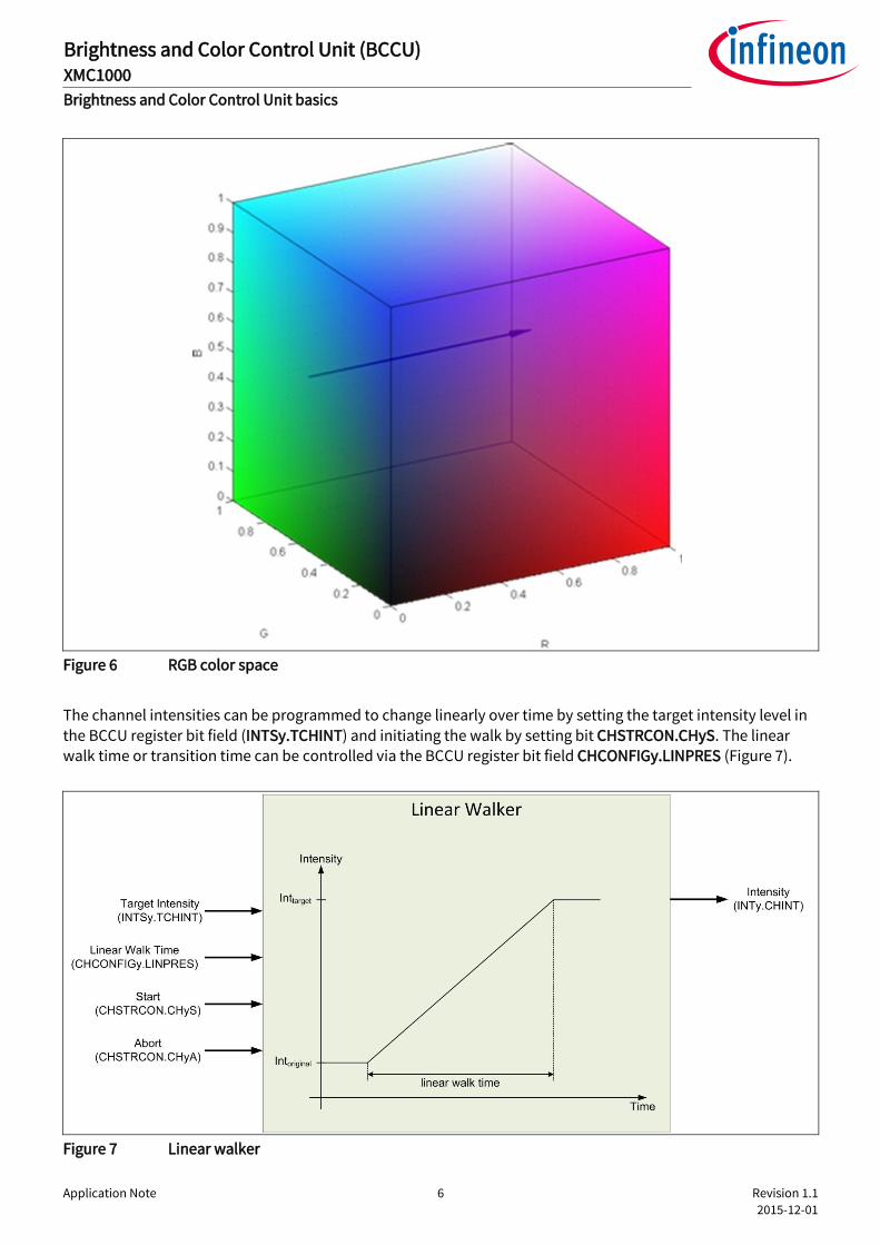
1.2.1 Linear walker
A smooth color transition can be achieved with the linear walker. A linear walk is simply a straight walk in the orthogonal color space, such as the RGB color space (Figure 6).
Application Note 6 Revision 1.1
2015-12-01
Brightness and Color Control Unit (BCCU) XMC1000
Brightness and Color Control Unit basics
Figure 6 RGB color space
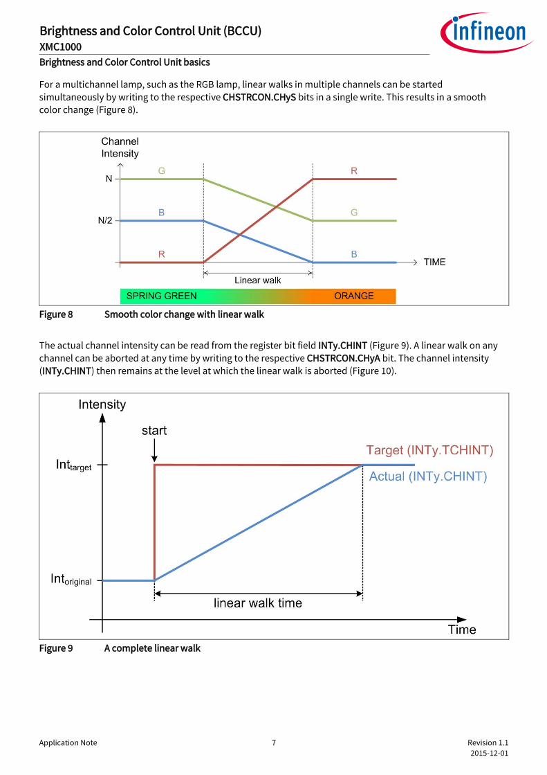
The channel intensities can be programmed to change linearly over time by setting the target intensity level in the BCCU register bit field (INTSy.TCHINT) and initiating the walk by setting bit CHSTRCON.CHyS. The linear walk time or transition time can be controlled via the BCCU register bit field CHCONFIGy.LINPRES (Figure 7).
Figure 7 Linear walker
Application Note 7 Revision 1.1
2015-12-01
Brightness and Color Control Unit (BCCU) XMC1000
Brightness and Color Control Unit basics
For a multichannel lamp, such as the RGB lamp, linear walks in multiple channels can be started simultaneously by writing to the respective CHSTRCON.CHyS bits in a single write. This results in a smooth color change (Figure 8).
Figure 8 Smooth color change with linear walk
The actual channel intensity can be read from the register bit field INTy.CHINT (Figure 9). A linear walk on any
channel can be aborted at any time by writing to the respective CHSTRCON.CHyA bit. The channel intensity (INTy.CHINT) then remains at the level at which the linear walk is aborted (Figure 10).
Figure 9 A complete linear walk
Application Note 8 Revision 1.1
2015-12-01
Brightness and Color Control Unit (BCCU) XMC1000
Brightness and Color Control Unit basics
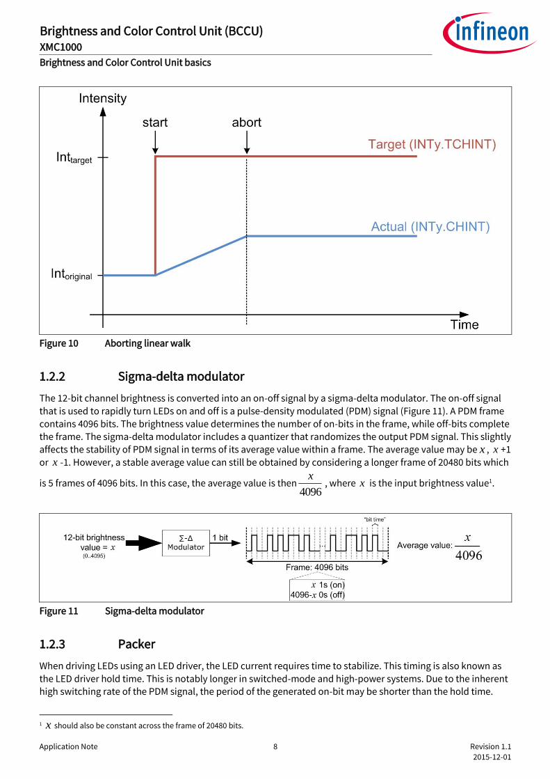
Figure 10 Aborting linear walk
1.2.2 Sigma-delta modulator
The 12-bit channel brightness is converted into an on-off signal by a sigma-delta modulator. The on-off signal
that is used to rapidly turn LEDs on and off is a pulse-density modulated (PDM) signal (Figure 11). A PDM frame
contains 4096 bits. The brightness value determines the number of on-bits in the frame, while off-bits complete the frame. The sigma-delta modulator includes a quantizer that randomizes the output PDM signal. This slightly
affects the stability of PDM signal in terms of its average value within a frame. The average value may be x , +1
or -1. However, a stable average value can still be obtained by considering a longer frame of 20480 bits which
is 5 frames of 4096 bits. In this case, the average value is then4096
x, where is the input brightness value1.
Figure 11 Sigma-delta modulator
1.2.3 Packer
When driving LEDs using an LED driver, the LED current requires time to stabilize. This timing is also known as
the LED driver hold time. This is notably longer in switched-mode and high-power systems. Due to the inherent high switching rate of the PDM signal, the period of the generated on-bit may be shorter than the hold time.
1 x should also be constant across the frame of 20480 bits.
x
x
x
Application Note 9 Revision 1.1
2015-12-01
Brightness and Color Control Unit (BCCU) XMC1000
Brightness and Color Control Unit basics
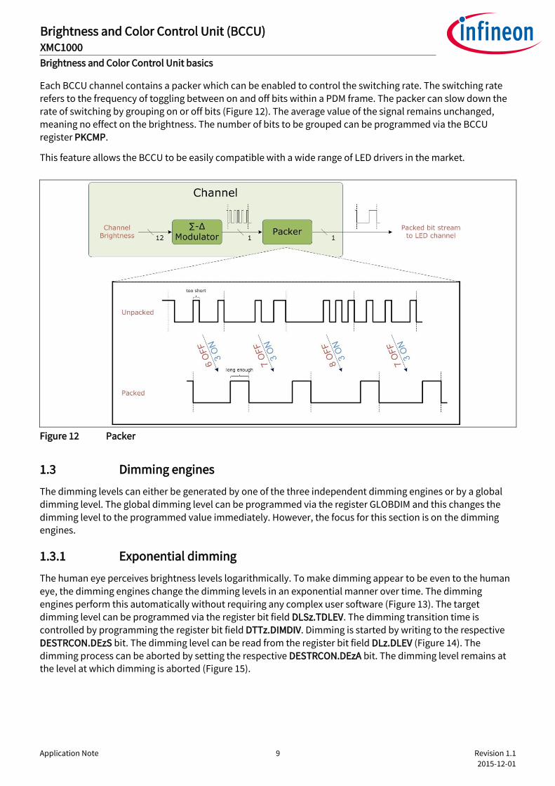
Each BCCU channel contains a packer which can be enabled to control the switching rate. The switching rate refers to the frequency of toggling between on and off bits within a PDM frame. The packer can slow down the
rate of switching by grouping on or off bits (Figure 12). The average value of the signal remains unchanged, meaning no effect on the brightness. The number of bits to be grouped can be programmed via the BCCU register PKCMP.
This feature allows the BCCU to be easily compatible with a wide range of LED drivers in the market.
Figure 12 Packer
1.3 Dimming engines
The dimming levels can either be generated by one of the three independent dimming engines or by a global dimming level. The global dimming level can be programmed via the register GLOBDIM and this changes the
dimming level to the programmed value immediately. However, the focus for this section is on the dimming engines.
1.3.1 Exponential dimming
The human eye perceives brightness levels logarithmically. To make dimming appear to be even to the human
eye, the dimming engines change the dimming levels in an exponential manner over time. The dimming engines perform this automatically without requiring any complex user software (Figure 13). The target dimming level can be programmed via the register bit field DLSz.TDLEV. The dimming transition time is controlled by programming the register bit field DTTz.DIMDIV. Dimming is started by writing to the respective
DESTRCON.DEzS bit. The dimming level can be read from the register bit field DLz.DLEV (Figure 14). The dimming process can be aborted by setting the respective DESTRCON.DEzA bit. The dimming level remains at the level at which dimming is aborted (Figure 15).

Application Note 10 Revision 1.1
2015-12-01
Brightness and Color Control Unit (BCCU) XMC1000
Brightness and Color Control Unit basics
Figure 13 Dimming engine
Figure 14 A complete dimming process

Application Note 11 Revision 1.1
2015-12-01
Brightness and Color Control Unit (BCCU) XMC1000
Brightness and Color Control Unit basics
Figure 15 Aborting a dimming process
1.3.2 Dither function
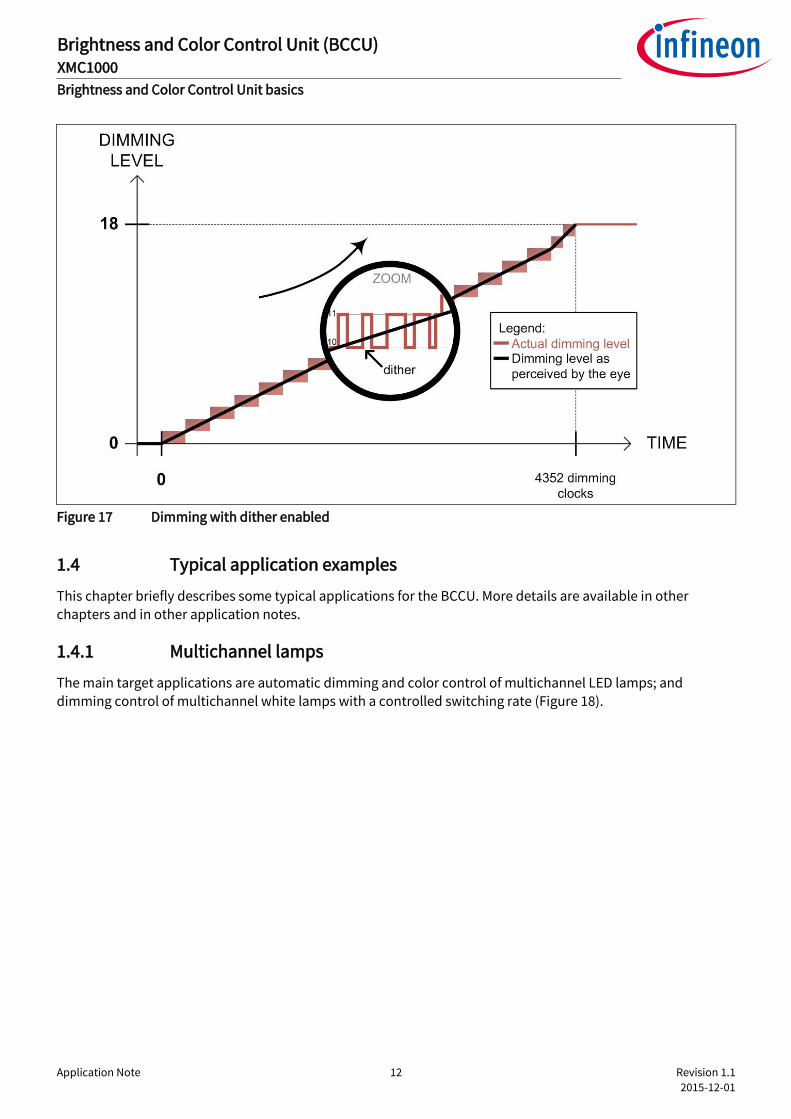
At low brightness levels, the human eye is much more sensitive to changes in illumination. For example, when
dimming up from dimming level 0 to dimming level 18, the change in brightness may appear “steppy” and
unnatural to the eye (Figure 16). To make the experience even smoother, dithering can be applied at low dimming levels (Figure 17). This function can be enabled by setting the register bit DTTz.DTEN.
Figure 16 Dimming without dither enabled
Application Note 12 Revision 1.1
2015-12-01
Brightness and Color Control Unit (BCCU) XMC1000
Brightness and Color Control Unit basics
Figure 17 Dimming with dither enabled
1.4 Typical application examples
This chapter briefly describes some typical applications for the BCCU. More details are available in other chapters and in other application notes.
1.4.1 Multichannel lamps
The main target applications are automatic dimming and color control of multichannel LED lamps; and dimming control of multichannel white lamps with a controlled switching rate (Figure 18).

Application Note 13 Revision 1.1
2015-12-01
Brightness and Color Control Unit (BCCU) XMC1000
Brightness and Color Control Unit basics
Figure 18 Multichannel LED Lamps
The BCCU is directly interconnected to the analog-digital converter (ADC) module via its trigger signals. This makes it convenient for fast, time-triggered lamp signal measurements, such as the LED string current, with minimum CPU load (Figure 19). These measurements can be used for various purposes such as open circuit detection, short circuit detection and variable bus voltage feedback.

Application Note 14 Revision 1.1
2015-12-01
Brightness and Color Control Unit (BCCU) XMC1000
Brightness and Color Control Unit basics
Figure 19 8-channel street lamp with ADC for signal measurement
The BCCU is also directly interconnected to capture and compare units, CCU4 and CCU8. This enables lamps to be controlled directly by the microcontroller without any switch-mode drivers (Figure 20).

Application Note 15 Revision 1.1
2015-12-01
Brightness and Color Control Unit (BCCU) XMC1000
Brightness and Color Control Unit basics
Figure 20 BCCU-CCU8 control of an RGB lamp without drivers
1.4.2 Simple digital-to-analog converter (DAC)
The BCCU can also be used as a simple DAC with one external resistor and one external capacitor as a filter (Figure 21).
Figure 21 Simple DAC with BCCU
Application Note 16 Revision 1.1
2015-12-01
Brightness and Color Control Unit (BCCU) XMC1000
Color LED lamp control with BCCU
2 Color LED lamp control with BCCU
This section intends to highlight the merits of using the BCCU to control color LED lamps, backed with a DAVETM example project.
2.1 Color LED lamp
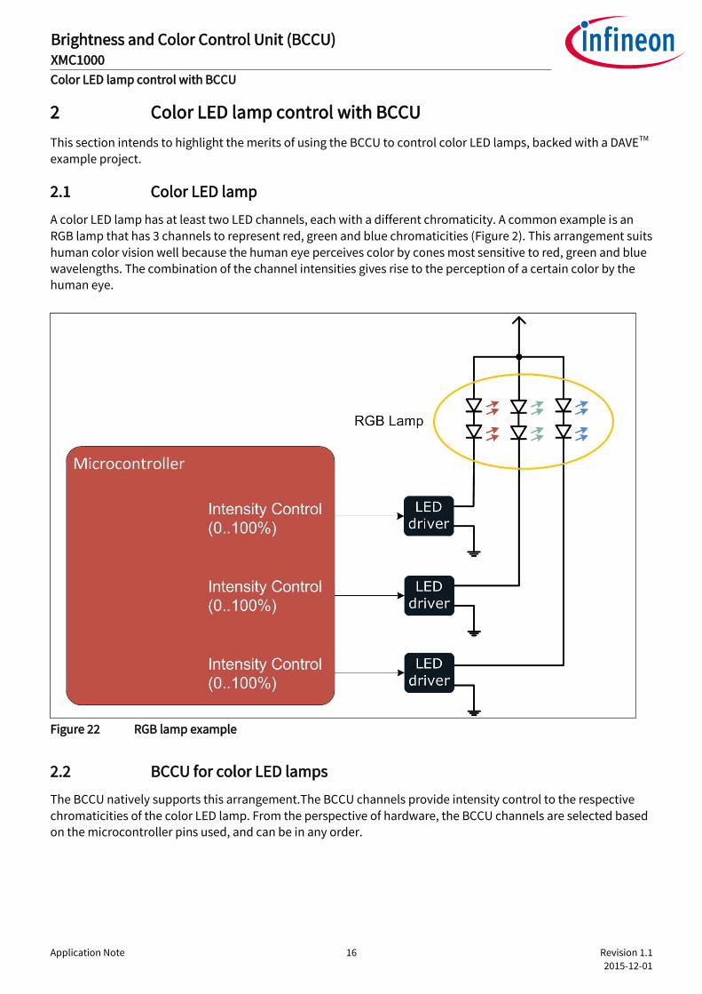
A color LED lamp has at least two LED channels, each with a different chromaticity. A common example is an
RGB lamp that has 3 channels to represent red, green and blue chromaticities (Figure 2). This arrangement suits
human color vision well because the human eye perceives color by cones most sensitive to red, green and blue wavelengths. The combination of the channel intensities gives rise to the perception of a certain color by the human eye.
Figure 22 RGB lamp example
2.2 BCCU for color LED lamps
The BCCU natively supports this arrangement.The BCCU channels provide intensity control to the respective
chromaticities of the color LED lamp. From the perspective of hardware, the BCCU channels are selected based on the microcontroller pins used, and can be in any order.
Application Note 17 Revision 1.1
2015-12-01
Brightness and Color Control Unit (BCCU) XMC1000
Color LED lamp control with BCCU
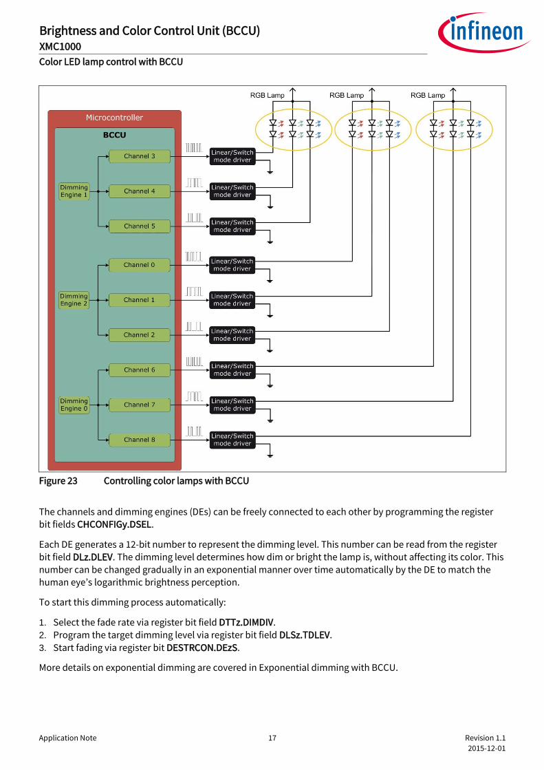
Figure 23 Controlling color lamps with BCCU
The channels and dimming engines (DEs) can be freely connected to each other by programming the register bit fields CHCONFIGy.DSEL.
Each DE generates a 12-bit number to represent the dimming level. This number can be read from the register bit field DLz.DLEV. The dimming level determines how dim or bright the lamp is, without affecting its color. This number can be changed gradually in an exponential manner over time automatically by the DE to match the human eye’s logarithmic brightness perception.
To start this dimming process automatically:
1. Select the fade rate via register bit field DTTz.DIMDIV. 2. Program the target dimming level via register bit field DLSz.TDLEV.
3. Start fading via register bit DESTRCON.DEzS.
More details on exponential dimming are covered in Exponential dimming with BCCU.
Application Note 18 Revision 1.1
2015-12-01
Brightness and Color Control Unit (BCCU) XMC1000
Color LED lamp control with BCCU
2.2.1 Controlling lamp color
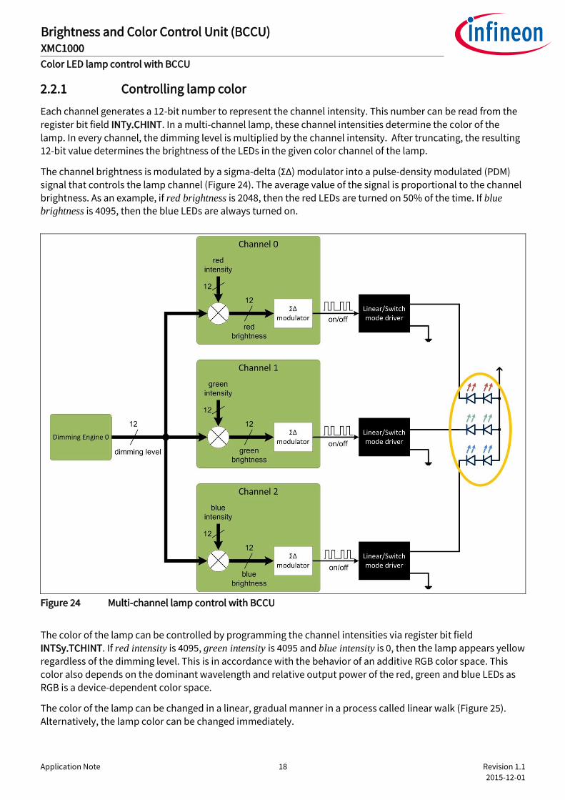
Each channel generates a 12-bit number to represent the channel intensity. This number can be read from the
register bit field INTy.CHINT. In a multi-channel lamp, these channel intensities determine the color of the
lamp. In every channel, the dimming level is multiplied by the channel intensity. After truncating, the resulting 12-bit value determines the brightness of the LEDs in the given color channel of the lamp.
The channel brightness is modulated by a sigma-delta (ΣΔ) modulator into a pulse-density modulated (PDM) signal that controls the lamp channel (Figure 24). The average value of the signal is proportional to the channel brightness. As an example, if red brightness is 2048, then the red LEDs are turned on 50% of the time. If blue
brightness is 4095, then the blue LEDs are always turned on.
Figure 24 Multi-channel lamp control with BCCU
The color of the lamp can be controlled by programming the channel intensities via register bit field INTSy.TCHINT. If red intensity is 4095, green intensity is 4095 and blue intensity is 0, then the lamp appears yellow regardless of the dimming level. This is in accordance with the behavior of an additive RGB color space. This
color also depends on the dominant wavelength and relative output power of the red, green and blue LEDs as RGB is a device-dependent color space.
The color of the lamp can be changed in a linear, gradual manner in a process called linear walk (Figure 25). Alternatively, the lamp color can be changed immediately.

Application Note 19 Revision 1.1
2015-12-01
Brightness and Color Control Unit (BCCU) XMC1000
Color LED lamp control with BCCU
Figure 25 Linear walk for a 3-channel lamp
To change the lamp color:
1. Set target intensity for each channel via register bit fields INTSy.TCHINT. 2. Set the transition time or linear walk time via register bit field CHCONFIGy.LINPRES. Set this parameter to 0
for an immediate change. 3. Start the linear walk via bit CHSTRCON.CHyS.
Note: For a smooth color change, the transition time has to be the same in all channels and the linear walks have to be started the same time by setting the respective CHSTRCON.CHyS bits in a single write.
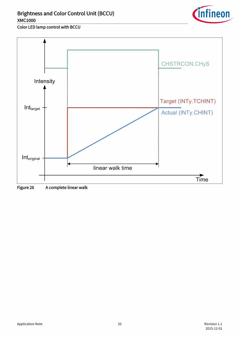
Bit CHSTRCON.CHyS resets automatically upon completion of the linear walk (Figure 26). A linear walk on any
channel can be aborted at any time by writing to the respective CHSTRCON.CHyA bit. The channel intensity (INTy.CHINT) then remains at the level at which the linear walk is aborted (Figure 27).
Application Note 20 Revision 1.1
2015-12-01
Brightness and Color Control Unit (BCCU) XMC1000
Color LED lamp control with BCCU
Figure 26 A complete linear walk

Application Note 21 Revision 1.1
2015-12-01
Brightness and Color Control Unit (BCCU) XMC1000
Color LED lamp control with BCCU
Figure 27 An aborted linear walk
2.3 RGB LED example
This section provides a guide to set up a basic project to control an RGB LED. This example demonstrates the linear walk feature of the BCCU.
The hardware required is:
XMC1200 Boot Kit
Color LED Card (Figure 28)
DAVETM is used as the development environment (Figure 29).

Application Note 22 Revision 1.1
2015-12-01
Brightness and Color Control Unit (BCCU) XMC1000
Color LED lamp control with BCCU
Figure 28 XMC1200 boot kit (left) and color LED card
Figure 29 DAVETM Integrated Development Environment by Infineon
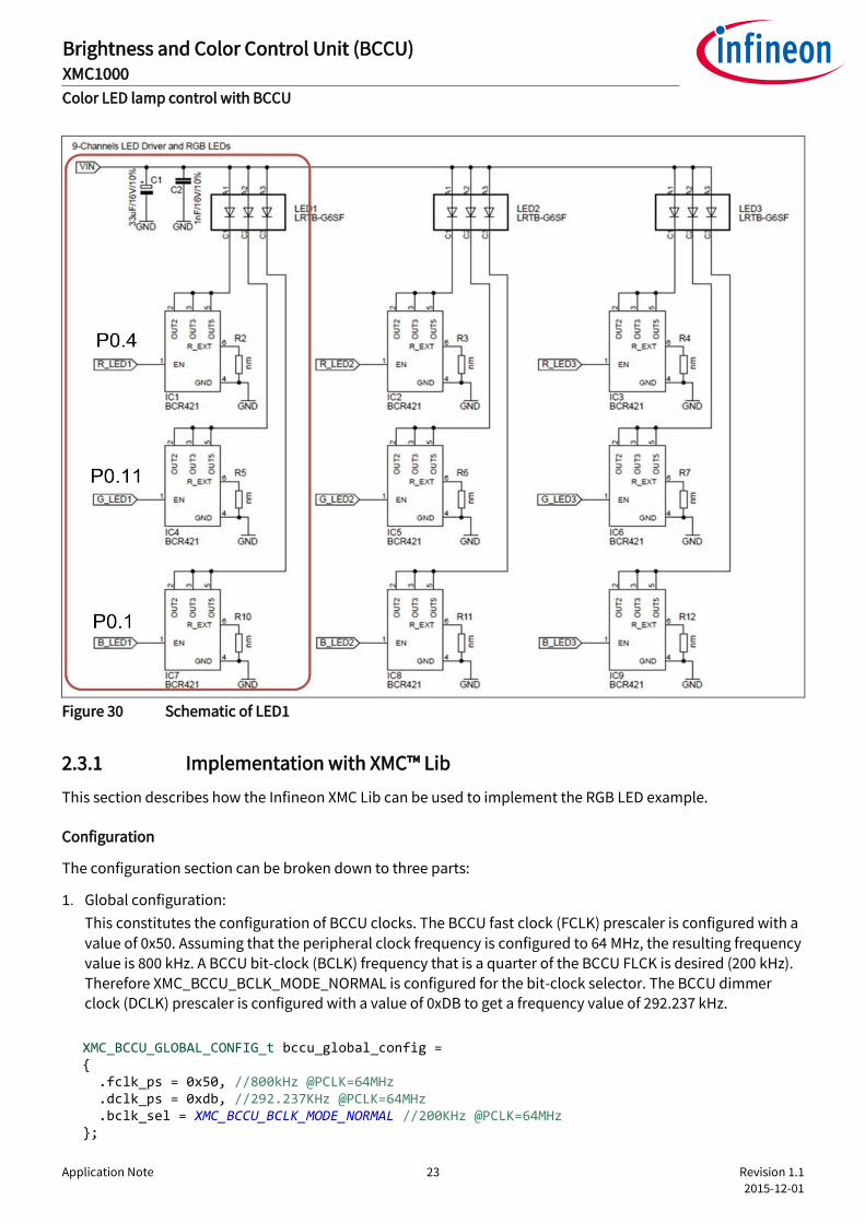
Only one of the RGB LEDs on the Color LED Card, LED1, is controlled in this example. The PDM output from three BCCU channels drives the LED drivers (BCR421) on each channel (Figure 30). The drivers in turn control
the current flow through the Red, Green and Blue LEDs of the LED module.
Application Note 23 Revision 1.1
2015-12-01
Brightness and Color Control Unit (BCCU) XMC1000
Color LED lamp control with BCCU
Figure 30 Schematic of LED1
2.3.1 Implementation with XMC™ Lib
This section describes how the Infineon XMC Lib can be used to implement the RGB LED example.
Configuration
The configuration section can be broken down to three parts:
1. Global configuration:
This constitutes the configuration of BCCU clocks. The BCCU fast clock (FCLK) prescaler is configured with a
value of 0x50. Assuming that the peripheral clock frequency is configured to 64 MHz, the resulting frequency value is 800 kHz. A BCCU bit-clock (BCLK) frequency that is a quarter of the BCCU FLCK is desired (200 kHz).
Therefore XMC_BCCU_BCLK_MODE_NORMAL is configured for the bit-clock selector. The BCCU dimmer clock (DCLK) prescaler is configured with a value of 0xDB to get a frequency value of 292.237 kHz.
XMC_BCCU_GLOBAL_CONFIG_t bccu_global_config = { .fclk_ps = 0x50, //800kHz @PCLK=64MHz .dclk_ps = 0xdb, //292.237KHz @PCLK=64MHz .bclk_sel = XMC_BCCU_BCLK_MODE_NORMAL //200KHz @PCLK=64MHz };
Application Note 24 Revision 1.1
2015-12-01
Brightness and Color Control Unit (BCCU) XMC1000
Color LED lamp control with BCCU
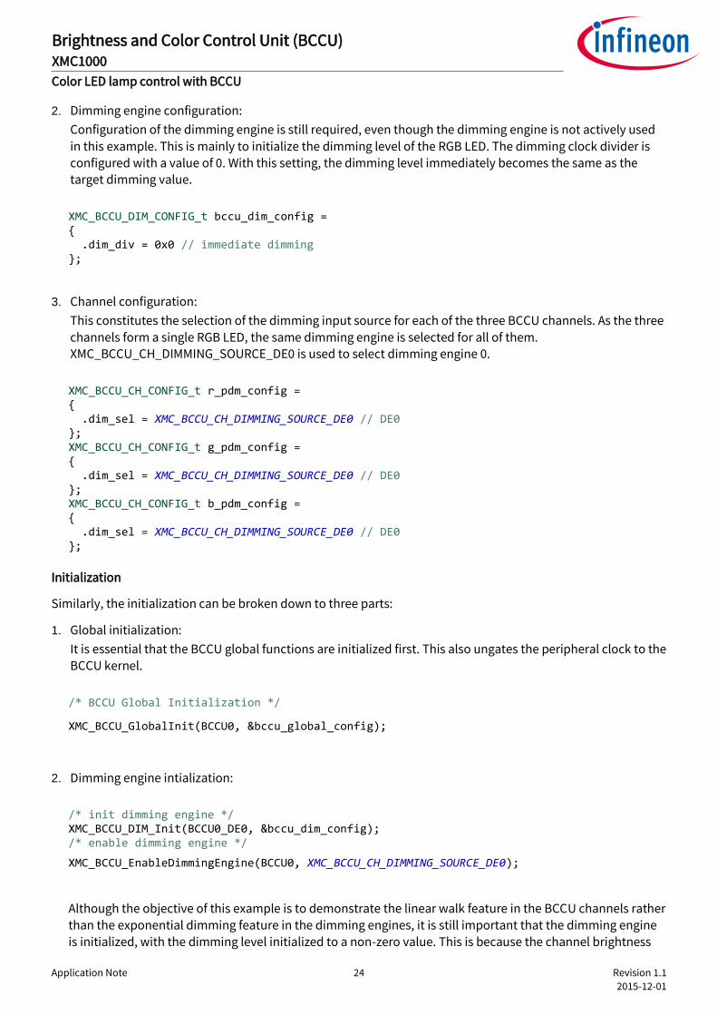
2. Dimming engine configuration:
Configuration of the dimming engine is still required, even though the dimming engine is not actively used
in this example. This is mainly to initialize the dimming level of the RGB LED. The dimming clock divider is configured with a value of 0. With this setting, the dimming level immediately becomes the same as the target dimming value.
XMC_BCCU_DIM_CONFIG_t bccu_dim_config = { .dim_div = 0x0 // immediate dimming };
3. Channel configuration:
This constitutes the selection of the dimming input source for each of the three BCCU channels. As the three
channels form a single RGB LED, the same dimming engine is selected for all of them. XMC_BCCU_CH_DIMMING_SOURCE_DE0 is used to select dimming engine 0.
XMC_BCCU_CH_CONFIG_t r_pdm_config = { .dim_sel = XMC_BCCU_CH_DIMMING_SOURCE_DE0 // DE0 }; XMC_BCCU_CH_CONFIG_t g_pdm_config = { .dim_sel = XMC_BCCU_CH_DIMMING_SOURCE_DE0 // DE0 }; XMC_BCCU_CH_CONFIG_t b_pdm_config = { .dim_sel = XMC_BCCU_CH_DIMMING_SOURCE_DE0 // DE0 };
Initialization
Similarly, the initialization can be broken down to three parts:
1. Global initialization:
It is essential that the BCCU global functions are initialized first. This also ungates the peripheral clock to the BCCU kernel.
/* BCCU Global Initialization */
XMC_BCCU_GlobalInit(BCCU0, &bccu_global_config);
2. Dimming engine intialization:
/* init dimming engine */ XMC_BCCU_DIM_Init(BCCU0_DE0, &bccu_dim_config); /* enable dimming engine */
XMC_BCCU_EnableDimmingEngine(BCCU0, XMC_BCCU_CH_DIMMING_SOURCE_DE0);
Although the objective of this example is to demonstrate the linear walk feature in the BCCU channels rather than the exponential dimming feature in the dimming engines, it is still important that the dimming engine
is initialized, with the dimming level initialized to a non-zero value. This is because the channel brightness
Application Note 25 Revision 1.1
2015-12-01
Brightness and Color Control Unit (BCCU) XMC1000
Color LED lamp control with BCCU
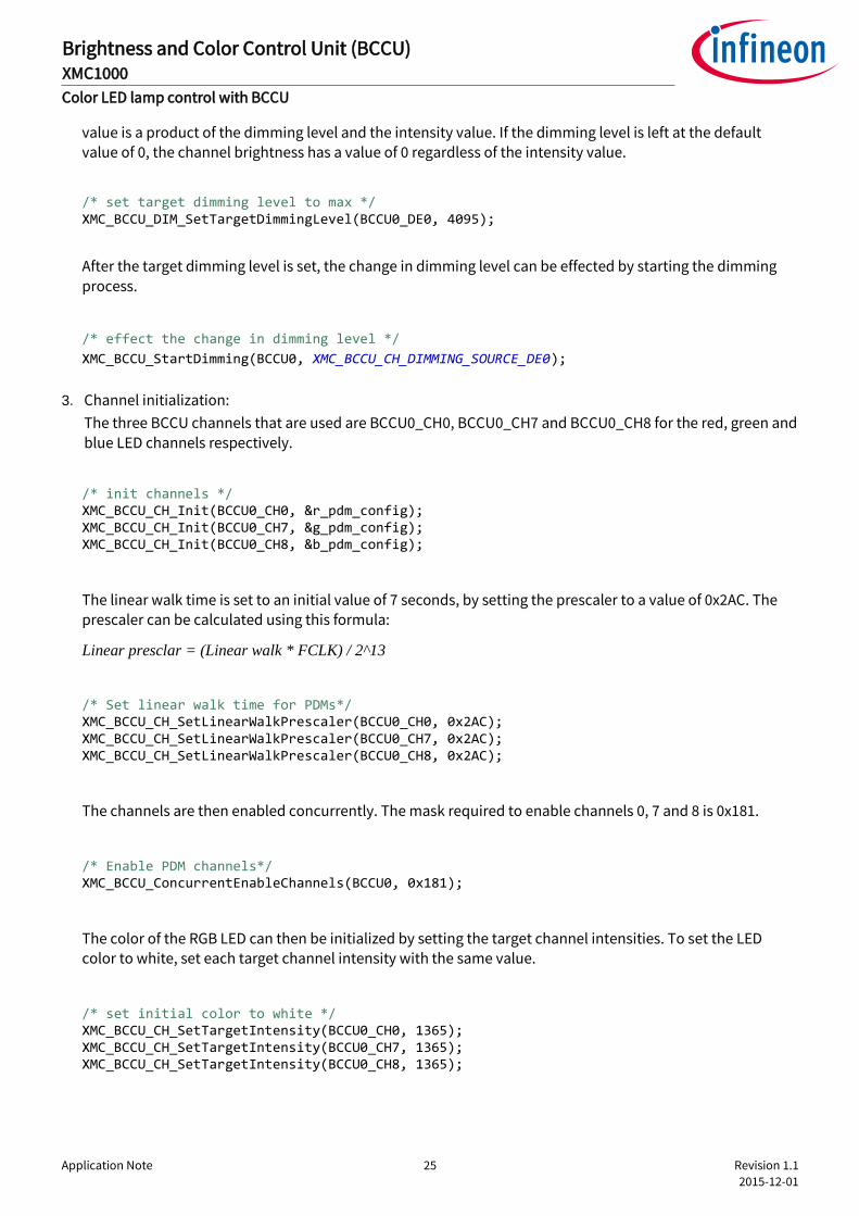
value is a product of the dimming level and the intensity value. If the dimming level is left at the default value of 0, the channel brightness has a value of 0 regardless of the intensity value.
/* set target dimming level to max */ XMC_BCCU_DIM_SetTargetDimmingLevel(BCCU0_DE0, 4095);
After the target dimming level is set, the change in dimming level can be effected by starting the dimming process.
/* effect the change in dimming level */
XMC_BCCU_StartDimming(BCCU0, XMC_BCCU_CH_DIMMING_SOURCE_DE0);
3. Channel initialization:
The three BCCU channels that are used are BCCU0_CH0, BCCU0_CH7 and BCCU0_CH8 for the red, green and blue LED channels respectively.
/* init channels */ XMC_BCCU_CH_Init(BCCU0_CH0, &r_pdm_config); XMC_BCCU_CH_Init(BCCU0_CH7, &g_pdm_config); XMC_BCCU_CH_Init(BCCU0_CH8, &b_pdm_config);
The linear walk time is set to an initial value of 7 seconds, by setting the prescaler to a value of 0x2AC. The prescaler can be calculated using this formula:
Linear presclar = (Linear walk * FCLK) / 2^13
/* Set linear walk time for PDMs*/ XMC_BCCU_CH_SetLinearWalkPrescaler(BCCU0_CH0, 0x2AC); XMC_BCCU_CH_SetLinearWalkPrescaler(BCCU0_CH7, 0x2AC); XMC_BCCU_CH_SetLinearWalkPrescaler(BCCU0_CH8, 0x2AC);
The channels are then enabled concurrently. The mask required to enable channels 0, 7 and 8 is 0x181.
/* Enable PDM channels*/ XMC_BCCU_ConcurrentEnableChannels(BCCU0, 0x181);
The color of the RGB LED can then be initialized by setting the target channel intensities. To set the LED color to white, set each target channel intensity with the same value.
/* set initial color to white */ XMC_BCCU_CH_SetTargetIntensity(BCCU0_CH0, 1365); XMC_BCCU_CH_SetTargetIntensity(BCCU0_CH7, 1365); XMC_BCCU_CH_SetTargetIntensity(BCCU0_CH8, 1365);
Application Note 26 Revision 1.1
2015-12-01
Brightness and Color Control Unit (BCCU) XMC1000
Color LED lamp control with BCCU
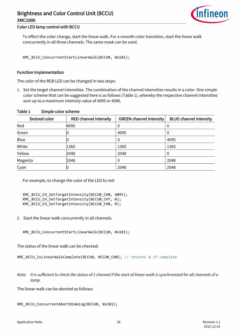
To effect the color change, start the linear walk. For a smooth color transition, start the linear walk concurrently in all three channels. The same mask can be used.
XMC_BCCU_ConcurrentStartLinearWalk(BCCU0, 0x181);
Function implementation
The color of the RGB LED can be changed in two steps:
1. Set the target channel intensities. The combination of the channel intensities results in a color. One simple color scheme that can be suggested here is as follows (Table 1), whereby the respective channel intensities sum up to a maximum intensity value of 4095 or 4096.
Table 1 Simple color scheme
Desired color RED channel intensity GREEN channel intensity BLUE channel intensity
Red 4095 0 0
Green 0 4095 0
Blue 0 0 4095
White 1365 1365 1365
Yellow 2048 2048 0
Magenta 2048 0 2048
Cyan 0 2048 2048
For example, to change the color of the LED to red:
XMC_BCCU_CH_SetTargetIntensity(BCCU0_CH0, 4095); XMC_BCCU_CH_SetTargetIntensity(BCCU0_CH7, 0); XMC_BCCU_CH_SetTargetIntensity(BCCU0_CH8, 0);
2. Start the linear walk concurrently in all channels.
XMC_BCCU_ConcurrentStartLinearWalk(BCCU0, 0x181);
The status of the linear walk can be checked:
XMC_BCCU_IsLinearWalkComplete(BCCU0, BCCU0_CH0); // returns 0 if complete
Note: It is sufficient to check the status of 1 channel if the start of linear walk is synchronized for all channels of a lamp.
The linear walk can be aborted as follows:
XMC_BCCU_ConcurrentAbortDimming(BCCU0, 0x181);

Application Note 27 Revision 1.1
2015-12-01
Brightness and Color Control Unit (BCCU) XMC1000
Color LED lamp control with BCCU
The respective channel intensities can then be read:
XMC_BCCU_CH_ReadIntensity(BCCU0_CH0); XMC_BCCU_CH_ReadIntensity(BCCU0_CH7); XMC_BCCU_CH_ReadIntensity(BCCU0_CH8);
2.3.2 Implementation with DAVETM APPs
PDM_DIMMED_LED_LAMP APP (Figure 31) allows for the configuration of up to nine channels in a lamp. In this
example, select 3 LED channels (Figure 32).
Figure 31 PDM_DIMMED_LED_LAMP APP in DAVETM
Figure 32 Select number of LED channels in PDM_DIMMED_LED_LAMP APP UI
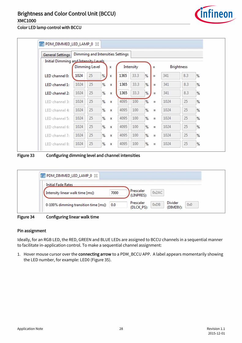
The dimming level and channel intensities can be configured in the PDM_DIMMED_LED_LAMP APP under the “Dimming and Intensities Settings” tab (Figure 33). For this example, the dimming level is kept constant. Only the channel intensities are changed in-application.
The linear walk time can also be configured under the same tab (Figure 34).
Application Note 28 Revision 1.1
2015-12-01
Brightness and Color Control Unit (BCCU) XMC1000
Color LED lamp control with BCCU
Figure 33 Configuring dimming level and channel intensities
Figure 34 Configuring linear walk time
Pin assignment
Ideally, for an RGB LED, the RED, GREEN and BLUE LEDs are assigned to BCCU channels in a sequential manner to facilitate in-application control. To make a sequential channel assignment:
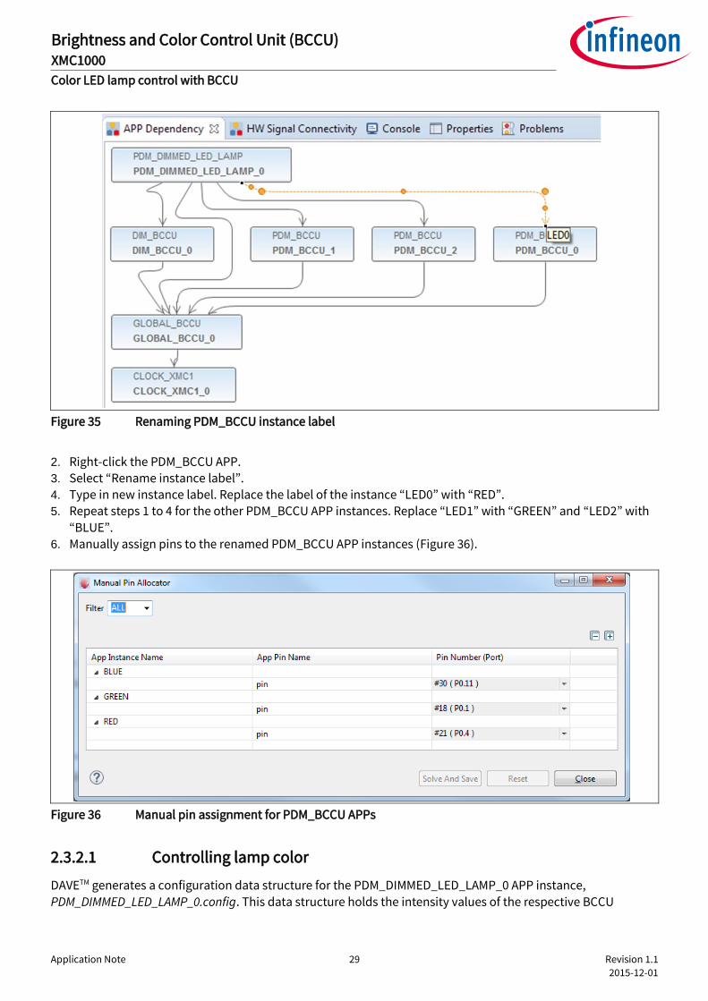
1. Hover mouse cursor over the connecting arrow to a PDM_BCCU APP. A label appears momentarily showing
the LED number, for example: LED0 (Figure 35).
Application Note 29 Revision 1.1
2015-12-01
Brightness and Color Control Unit (BCCU) XMC1000
Color LED lamp control with BCCU
Figure 35 Renaming PDM_BCCU instance label
2. Right-click the PDM_BCCU APP. 3. Select “Rename instance label”.
4. Type in new instance label. Replace the label of the instance “LED0” with “RED”. 5. Repeat steps 1 to 4 for the other PDM_BCCU APP instances. Replace “LED1” with “GREEN” and “LED2” with
“BLUE”.
6. Manually assign pins to the renamed PDM_BCCU APP instances (Figure 36).
Figure 36 Manual pin assignment for PDM_BCCU APPs
2.3.2.1 Controlling lamp color
DAVETM generates a configuration data structure for the PDM_DIMMED_LED_LAMP_0 APP instance,
PDM_DIMMED_LED_LAMP_0.config. This data structure holds the intensity values of the respective BCCU
Application Note 30 Revision 1.1
2015-12-01
Brightness and Color Control Unit (BCCU) XMC1000
Color LED lamp control with BCCU
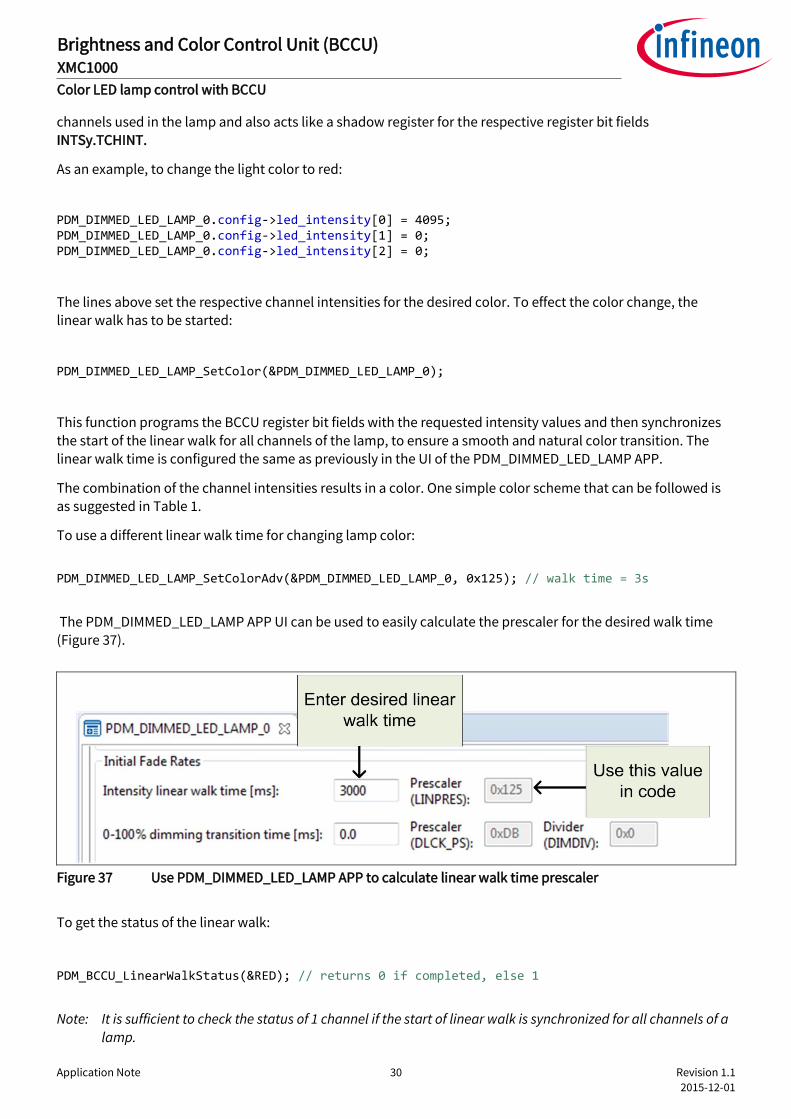
channels used in the lamp and also acts like a shadow register for the respective register bit fields INTSy.TCHINT.
As an example, to change the light color to red:
PDM_DIMMED_LED_LAMP_0.config->led_intensity[0] = 4095; PDM_DIMMED_LED_LAMP_0.config->led_intensity[1] = 0; PDM_DIMMED_LED_LAMP_0.config->led_intensity[2] = 0;
The lines above set the respective channel intensities for the desired color. To effect the color change, the linear walk has to be started:
PDM_DIMMED_LED_LAMP_SetColor(&PDM_DIMMED_LED_LAMP_0);
This function programs the BCCU register bit fields with the requested intensity values and then synchronizes
the start of the linear walk for all channels of the lamp, to ensure a smooth and natural color transition. The linear walk time is configured the same as previously in the UI of the PDM_DIMMED_LED_LAMP APP.
The combination of the channel intensities results in a color. One simple color scheme that can be followed is as suggested in Table 1.
To use a different linear walk time for changing lamp color:
PDM_DIMMED_LED_LAMP_SetColorAdv(&PDM_DIMMED_LED_LAMP_0, 0x125); // walk time = 3s
The PDM_DIMMED_LED_LAMP APP UI can be used to easily calculate the prescaler for the desired walk time (Figure 37).
Figure 37 Use PDM_DIMMED_LED_LAMP APP to calculate linear walk time prescaler
To get the status of the linear walk:
PDM_BCCU_LinearWalkStatus(&RED); // returns 0 if completed, else 1
Note: It is sufficient to check the status of 1 channel if the start of linear walk is synchronized for all channels of a lamp.

Application Note 31 Revision 1.1
2015-12-01
Brightness and Color Control Unit (BCCU) XMC1000
Color LED lamp control with BCCU
Alternatively, the application can wait indefinitely for the end of linear walk:
PDM_BCCU_AwaitEndOfLinearWalk(&RED); // wait till linear walk is complete
The linear walk can be aborted as follows:
PDM_DIMMED_LED_LAMP_AbortColorChange(&PDM_DIMMED_LED_LAMP_0);
To get the respective channel intensities after a linear walk abort:
PDM_BCCU_GetIntensity(&RED); // intensity value of Red channel PDM_BCCU_GetIntensity(&GREEN); // intensity value of Green channel PDM_BCCU_GetIntensity(&BLUE); // intensity value of Blue channel
Application Note 32 Revision 1.1
2015-12-01
Brightness and Color Control Unit (BCCU) XMC1000
Exponential dimming with BCCU
3 Exponential dimming with BCCU
This section provides hints on using the dimming engine to achieve smooth and natural LED light dimming.
3.1 Dimming engine
At the heart of the dimming functionality in the BCCU are its dimming engines. A dimming engine can be simply
viewed as a number generator. It always holds a certain number, which is the current dimming level. Based on
the configuration and the request (target dimming level) that it received, the BCCU periodically increments or decrements its number towards the requested number, which then becomes the current dimming level.
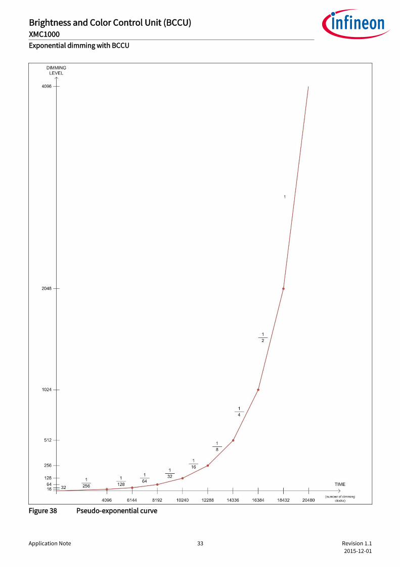
Studies have shown that the human eye perceives light according to a logarithmic pattern. To compensate for
this, in order for the transition to look even to the human eye, the dimming engine attempts to change its
number in an exponential fashion. To achieve this, straight lines of differing gradient are pieced together to form a pseudo-exponential curve (Figure 38).
Application Note 33 Revision 1.1
2015-12-01
Brightness and Color Control Unit (BCCU) XMC1000
Exponential dimming with BCCU
Figure 38 Pseudo-exponential curve

Application Note 34 Revision 1.1
2015-12-01
Brightness and Color Control Unit (BCCU) XMC1000
Exponential dimming with BCCU
The BCCU offers two options for this pseudo-exponential curve – coarse and fine. The fine pseudo-exponential curve is made up of more pieces of straight lines of differing gradient. This option can be configured via the register bit DTTz.CSEL.
The dimming engines perform dimming following the selected exponential curve automatically without requiring any complex user software. To change the dim level of a lamp:
1. Program target dim level via the register bit field DLSz.TDLEV. 2. Program dimming transition time via the register bit field DTTz.DIMDIV.
3. Start dimming process by writing to the respective DESTRCON.DEzS bit.
Note: This same register bit can also be used to check if the dimming process is complete as it is cleared by hardware upon completion.
The dimming level can be read from the register bit field DLz.DLEV. A dimming process can be aborted by
setting the respective DESTRCON.DEzA bit. The dimming level remains at the level at which dimming is aborted.
The dimming engine allows the BCCU to control the dim level of a lamp independently from the lamp’s color component (Figure 39). This is especially beneficial in the case of color lamps, where the BCCU is able to maintain the lamp color while changing its dim level (Figure 40).
Figure 39 Separate control of dim level and color
Application Note 35 Revision 1.1
2015-12-01
Brightness and Color Control Unit (BCCU) XMC1000
Exponential dimming with BCCU
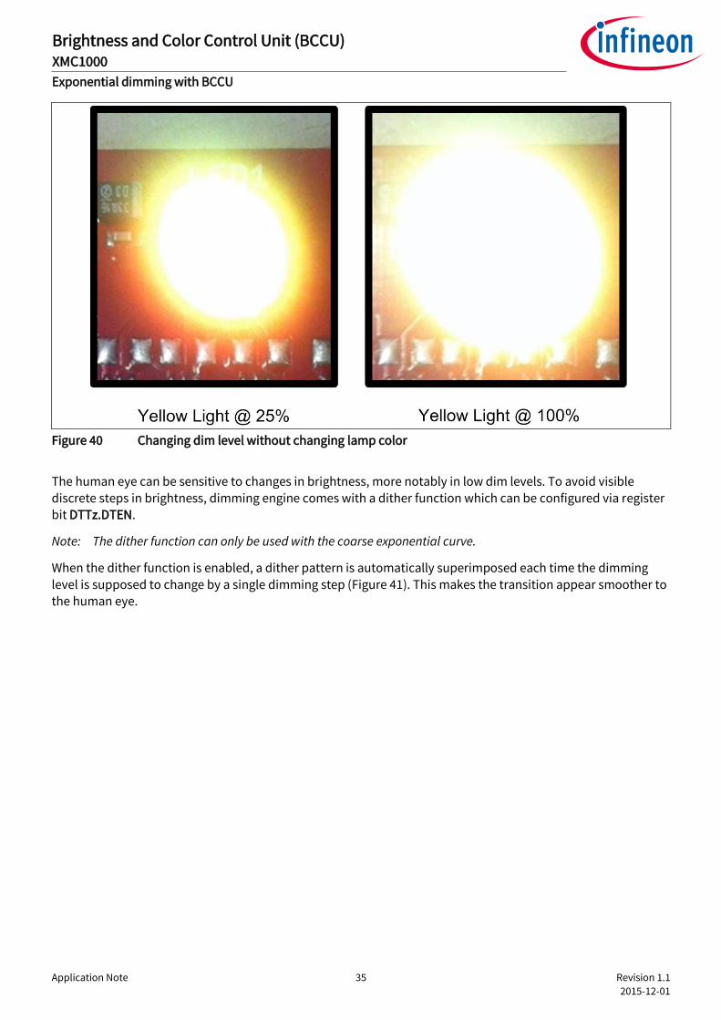
Figure 40 Changing dim level without changing lamp color
The human eye can be sensitive to changes in brightness, more notably in low dim levels. To avoid visible discrete steps in brightness, dimming engine comes with a dither function which can be configured via register bit DTTz.DTEN.
Note: The dither function can only be used with the coarse exponential curve.
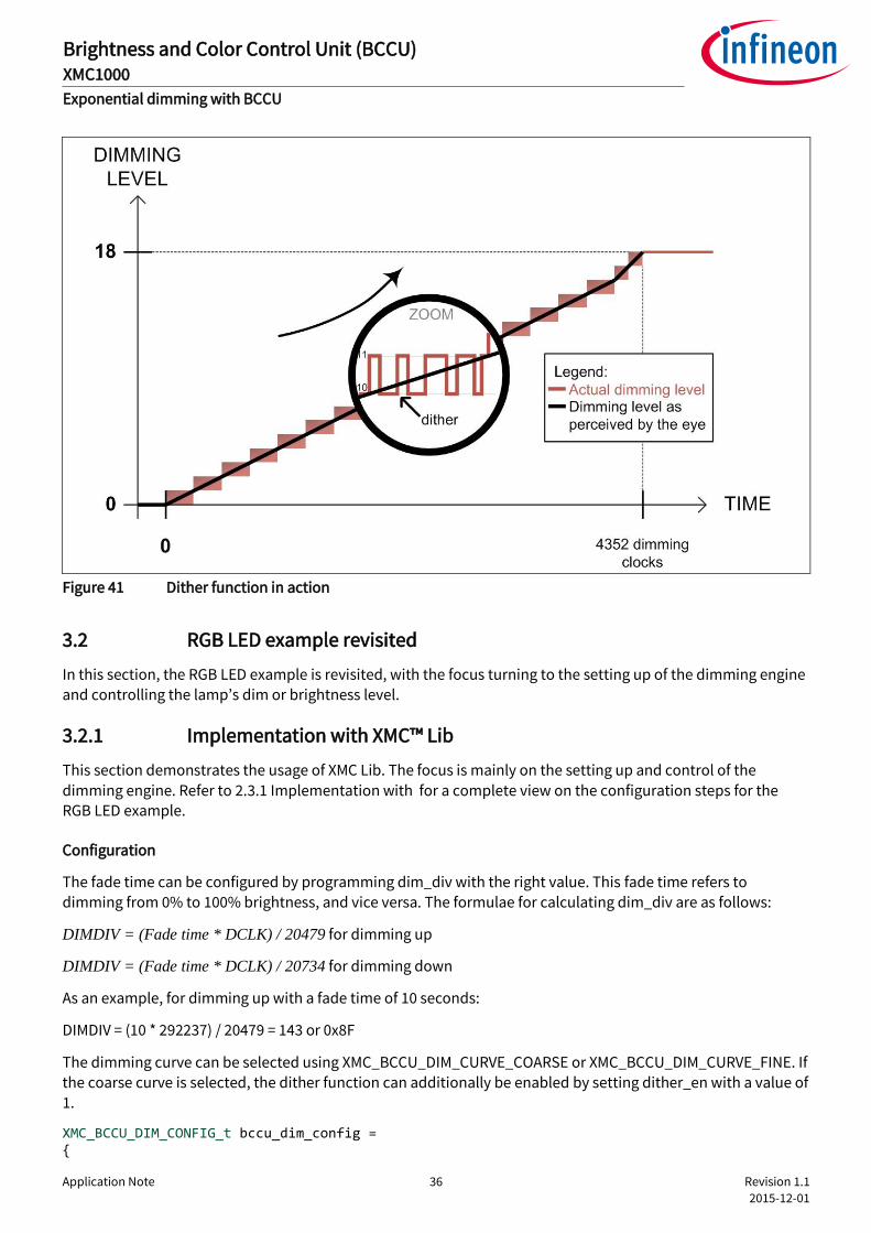
When the dither function is enabled, a dither pattern is automatically superimposed each time the dimming
level is supposed to change by a single dimming step (Figure 41). This makes the transition appear smoother to the human eye.
Application Note 36 Revision 1.1
2015-12-01
Brightness and Color Control Unit (BCCU) XMC1000
Exponential dimming with BCCU
Figure 41 Dither function in action
3.2 RGB LED example revisited
In this section, the RGB LED example is revisited, with the focus turning to the setting up of the dimming engine
and controlling the lamp’s dim or brightness level.
3.2.1 Implementation with XMC™ Lib
This section demonstrates the usage of XMC Lib. The focus is mainly on the setting up and control of the
dimming engine. Refer to 2.3.1 Implementation with for a complete view on the configuration steps for the RGB LED example.
Configuration
The fade time can be configured by programming dim_div with the right value. This fade time refers to
dimming from 0% to 100% brightness, and vice versa. The formulae for calculating dim_div are as follows:
DIMDIV = (Fade time * DCLK) / 20479 for dimming up
DIMDIV = (Fade time * DCLK) / 20734 for dimming down
As an example, for dimming up with a fade time of 10 seconds:
DIMDIV = (10 * 292237) / 20479 = 143 or 0x8F
The dimming curve can be selected using XMC_BCCU_DIM_CURVE_COARSE or XMC_BCCU_DIM_CURVE_FINE. If the coarse curve is selected, the dither function can additionally be enabled by setting dither_en with a value of 1.
XMC_BCCU_DIM_CONFIG_t bccu_dim_config = {

Application Note 37 Revision 1.1
2015-12-01
Brightness and Color Control Unit (BCCU) XMC1000
Exponential dimming with BCCU
.dim_div = 0x8F, // fade time of 10s .dither_en = 1, // enable dither .cur_sel = XMC_BCCU_DIM_CURVE_COARSE // coarse dimming curve };
Initialization
The example below shows the initialization and enabling of dimming engine 0. For dimming engine 1 and 2, BCCU0_DE1 and BCCU0_DE2 can be used respectively in place of BCCU0_DE0.
/* init dimming engine */ XMC_BCCU_DIM_Init(BCCU0_DE0, &bccu_dim_config); /* enable dimming engine */ XMC_BCCU_EnableDimmingEngine(BCCU0, XMC_BCCU_CH_DIMMING_SOURCE_DE0);
Function implementation
To change the lamp brightness, the target dimming level must be set first:
/* set target dimming level to max */ XMC_BCCU_DIM_SetTargetDimmingLevel(BCCU0_DE0, 4095);
After the target dimming level is set, the change in dimming level can be effected by starting the dimming process:
/* start dimming process */ XMC_BCCU_StartDimming(BCCU0, XMC_BCCU_CH_DIMMING_SOURCE_DE0);
To change the fade time, use the following function before starting the dimming process:
/* set fade time to 3s */ XMC_BCCU_DIM_SetDimDivider(BCCU0_DE0, 0x2B);
The dimming status can be checked:
/* check dim status: returns 0 if complete */
status = XMC_BCCU_IsDimmingFinished(BCCU0, XMC_BCCU_CH_DIMMING_SOURCE_DE0);
The dimming process can be aborted as follows:
XMC_BCCU_AbortDimming(BCCU0, XMC_BCCU_CH_DIMMING_SOURCE_DE0);

Application Note 38 Revision 1.1
2015-12-01
Brightness and Color Control Unit (BCCU) XMC1000
Exponential dimming with BCCU
To get the last dim level after a dimming process abort:
XMC_BCCU_DIM_ReadDimmingLevel(BCCU0_DE0); // read current dim level
3.2.2 Implementation with DAVETM APPs
This section demonstrates the usage of DAVETM APPs. The focus is mainly on setting up and controlling the dimming engine. Refer to 2.3.2 Implementation with DAVETM APPs for a complete view on the configuration steps for the RGB LED.
The lamp’s initial dimming level and dimming transition time can be configured in the PDM_DIMMED_LED_LAMP APP under the “Dimming and Intensities Settings” tab (Figure 42).
Figure 42 Configuring initial dimming level and transition time
Note: The dimming transition time configured here is for a transition from dim level of 0% to 100%. For any smaller transitions, the time taken is scaled according to the exponential curve. For example, referring to Figure 38:
If dimming up from 0% to 100% which takes 20480 dimming clocks is equivalent to 10 seconds, then
dimming up from 0% to 50% which takes 18432 dimming clocks is equivalent to 9 seconds.

Application Note 39 Revision 1.1
2015-12-01
Brightness and Color Control Unit (BCCU) XMC1000
Exponential dimming with BCCU
The dimming curve can be selected in the DIM_BCCU APP via a drop-down box (Figure 43). The dither function can also be enabled by selecting the check-box in the same APP.
Figure 43 Selecting dimming curve and enabling dither function
3.2.2.1 Controlling lamp brightness
The DAVETM-generated configuration data structure, PDM_DIMMED_LED_LAMP_0.config, for the
PDM_DIMMED_LED_LAMP_0 APP instance also holds the dim level value of the dimming engine used in the lamp. It acts like a shadow register for the respective register bit field DLSz.TDLEV.
As an example, to change the dim level to 100%:
PDM_DIMMED_LED_LAMP_0_config.dim_level = 4095;
The line above sets the dimming engine target level for the desired dim level. To effect the brightness change, the dimming process has to be started:
PDM_DIMMED_LED_LAMP_SetDimLevelExponential(&PDM_DIMMED_LED_LAMP_0);
This function programs the BCCU register bit fields with the configured dimming transition time, the target
dimming level and starts the dimming process. The dimming transition time used configured the same way as previously in the UI of the PDM_DIMMED_LED_LAMP APP.
To use a different dimming transition time for changing lamp brightness:
/* Configure dimming transition time = 3s, and start dimming process */ PDM_DIMMED_LED_LAMP_SetDimLevelExponentialAdv(&PDM_DIMMED_LED_LAMP_0, 0x2B, 0xDB);

Application Note 40 Revision 1.1
2015-12-01
Brightness and Color Control Unit (BCCU) XMC1000
Exponential dimming with BCCU
The PDM_DIMMED_LED_LAMP APP UI can be used to easily calculate the prescaler and divider values for the desired dimming transition time (Figure 44).
Figure 44 Use PDM_DIMMED_LED_LAMP APP to calculate dimming transition time prescaler and divider
To get the status of the dimming process:
DIM_BCCU_FadeCompletionStatus(&DIM_BCCU_0); // returns 0 if completed, else 1
Alternatively, the application can wait indefinitely for the end of dimming process:
DIM_BCCU_AwaitFadeCompletion(&DIM_BCCU_0); // wait till dimming process is complete
The dimming process can be aborted as follows:
DIM_BCCU_AbortDimming(&DIM_BCCU_0);
To get the last dim level after a dimming process abort:
DIM_BCCU_GetDimLvl(&DIM_BCCU_0); // read current dim level

Application Note 41 Revision 1.1
2015-12-01
Revision history
Brightness and Color Control Unit (BCCU) XMC1000
Revision history
Major changes since the last revision
Page or Reference Description of change
1.2.3 Enhanced packer description.
Figure 21 Updated figure for using BCCU channel as pseudo-DAC.
2.3.2, 3.2.2 Updated LED_LAMP APP to PDM_DIMMED_LED_LAMP APP due to APP name change in
DAVE™.
Trademarks of Infineon Technologies AG AURIX™, C166™, CanPAK™, CIPOS™, CoolGaN™, CoolMOS™, CoolSET™, CoolSiC™, CORECONTROL™, CROSSAVE™, DAVE™, DI-POL™, DrBlade™, EasyPIM™, EconoBRIDGE™, EconoDUAL™, EconoPACK™, EconoPIM™, EiceDRIVER™, eupec™, FCOS™, HITFET™, HybridPACK™, Infineon™, ISOFACE™, IsoPACK™, i-Wafer™, MIPAQ™, ModSTACK™, my-d™, NovalithIC™, OmniTune™, OPTIGA™, OptiMOS™, ORIGA™, POWERCODE™, PRIMARION™, PrimePACK™, PrimeSTACK™, PROFET™, PRO-SIL™, RASIC™, REAL3™, ReverSave™, SatRIC™, SIEGET™, SIPMOS™, SmartLEWIS™, SOLID FLASH™, SPOC™, TEMPFET™, thinQ!™, TRENCHSTOP™, TriCore™. Trademarks updated August 2015
Other Trademarks All referenced product or service names and trademarks are the property of their respective owners. ifx1owners.
Edition 2015-12-01
AP32275
Published by
Infineon Technologies AG
81726 Munich, Germany
© 2015 Infineon Technologies AG.
All Rights Reserved.
Do you have a question about this document?
Email: [email protected]
Document reference
IMPORTANT NOTICE The information contained in this application note is given as a hint for the implementation of the product only and shall in no event be regarded as a description or warranty of a certain functionality, condition or quality of the product. Before implementation of the product, the recipient of this application note must verify any function and other technical information given herein in the real application. Infineon Technologies hereby disclaims any and all warranties and liabilities of any kind (including without limitation warranties of non-infringement of intellectual property rights of any third party) with respect to any and all information given in this application note. The data contained in this document is exclusively intended for technically trained staff. It is the responsibility of customer’s technical departments to evaluate the suitability of the product for the intended application and the completeness of the product information given in this document with respect to such application.
For further information on the product, technology, delivery terms and conditions and prices please contact your nearest Infineon Technologies office (www.infineon.com).
WARNINGS Due to technical requirements products may contain dangerous substances. For information on the types in question please contact your nearest Infineon Technologies office. Except as otherwise explicitly approved by Infineon Technologies in a written document signed by authorized representatives of Infineon Technologies, Infineon Technologies’ products may not be used in any applications where a failure of the product or any consequences of the use thereof can reasonably be expected to result in personal injury.