AP300 Combination pH/Redox (ORP) sensors · AP300 | Combination pH/Redox (ORP) sensors | IM/AP300...
20
— ABB MEASUREMENT & ANALYTICS | USER GUIDE | IM/AP300 REV. J AP300 Combination pH/Redox (ORP) sensors Measurement made easy Introduction The AP300 range of pH/Redox sensors offers a reliable and cost-effective solution for most industrial pH applications. It is the perfect starting point for pH or Redox measurements. Combining measurement, reference and temperature compensation elements in a single unit, the AP300 is an economical solution for a wide variety of industrial applications; including water, food, pharmaceutical and chemical. Sales Service
Transcript of AP300 Combination pH/Redox (ORP) sensors · AP300 | Combination pH/Redox (ORP) sensors | IM/AP300...

— A B B M E A SU R EM ENT & A N A LY TI C S | US ER G U I DE | I M/A P3 0 0 R E V. J
AP300Combination pH/Redox (ORP) sensors
Measurement made easy
IntroductionThe AP300 range of pH/Redox sensors offers a reliable and cost-effective solution for most industrial pH applications. It is the perfect starting point for pH or Redox measurements.
Combining measurement, reference and temperature compensation elements in a single unit, the AP300 is an economical solution for a wide variety of industrial applications; including water, food, pharmaceutical and chemical.
Sales
Service

2 IM/AP300 Rev. J | AP300 | Combination pH/Redox (ORP) sensors
Contents
1 Introduction ...............................................................31.1 Purpose ....................................................................... 31.2 Sensors and Systems .................................................. 31.3 Sensor Descriptions ..................................................... 3
1.3.1 AP301 .............................................................. 31.3.2 AP302/3 Sensors ............................................. 41.3.3 AP304/5 Sensors ............................................. 5
2 Mechanical Installation .............................................72.1 Recommended Installation ........................................... 7
2.1.1 AP301 Sensors ................................................ 82.1.2 AP302/3 Sensors ............................................. 92.1.3 AP304/5 Sensors ........................................... 10
3 Electrical Connections ............................................123.1 Sensor Connections .................................................. 123.2 Extension Cables ....................................................... 13
4 Calibration ................................................................144.1 pH Sensor ................................................................. 144.2 Redox (ORP Sensor) .................................................. 14
5 Maintenance ............................................................155.1 General Cleaning ....................................................... 15
5.1.1 General Sludge and Loosely Adhering Matter ................................. 15
5.1.2 Heavy, Non-Greasy Deposits .......................... 155.1.3 Greasy or Organic Deposits ............................ 15
5.2 Fault Finding .............................................................. 155.3 Storage of the Electrode ............................................ 15
6 Spares and Accessories .........................................16
7 Specification ............................................................17
Notes .............................................................................18

AP300 | Combination pH/Redox (ORP) sensors | IM/AP300 Rev. J 3
1 Introduction1.1 PurposeThis instruction manual describes the installation and maintenance of the AP300 Series Industrial pH and Redox (ORP) Electrode Systems.
1.2 Sensors and SystemsThere are three main sensor types:
— AP301 Standard twist-lock – insertion, flow-through, immersion
— AP302 Screw in – insertion, immersion
— AP304/5 Ball valve insertion, hot-tap
1.3 Sensor Descriptions
1.3.1 AP301Model AP301 sensors are twist-lock general purpose insertion, flow-through or immersion style. The sensor body is molded from chemically resistant PPS (Ryton).
The sensor can be adapted to 1 inch fittings by a threaded Ryton twist-lock adaptor.
An optional PVC electrode guard protects the electrode in immersion applications.
Dimensions in mm (in.)
Fig. 1.1 AP301 Sensors and Dimensions
�����������
�������
�������� �
�������������������
����������
��� ������
������ ��
���������
� ����������
Sensor
No. 1 18 VitonO-Rings 2 Each
1 in. NPT Flow Cell(Part No. 7670046)
Optional Threaded Adaptor
Optional PVC Immersion Guard
Sensor with Optional Junction Box
3/4 in. NPT Conduit Port
3/4 in. NPT Electrode
Flow
3/4 in. NPT Flex Conduit and Coupling

4 IM/AP300 Rev. J | AP300 | Combination pH/Redox (ORP) sensors
1.3.2 AP302/3 SensorsThese sensors are threaded style suitable for immersion, insertion and flow-through applications.
Mounting thread size: 3/4 inch NPT.
The sensor body is chemically resistant PVDF (Kynar).
— AP302 models have no sensor guard (flush) for use with flat glass. This provides a flow-cleaned configuration.
— AP303 models have a notched sensor guard. The guard provides an integral protection for normal bulb-style glasses.
Dimensions in mm (in.)
Fig. 1.2 AP302/3 Sensors and Dimensions
���������
�� ��������
����������
������ ��
�������� ����������
���������
Rear of Sensor and Cable to be Sealed in Conduit or Pipe (Customer Supplied)
3/4 in. Coupling (Customer Supplied)
AP302 (Flush) Sensor AP303 (Notched) Sensor Immersion Applications
AP303 (Notched) SensorFlow Applications
AP303 (Notched) Sensor with Optional Junction Box
3/4 in. NPT Conduit Port
Sample Outlet
3/4 in. Flow Cell(Customer Supplied)
Conduit(Customer Supplied)
Sample Inlet
Electrode
38.1 (1.5) Insertion length
7/8 in. Wrench Flats
3/4 in. NPT
3/4 in. NPT
3/4 in. NPT

AP300 | Combination pH/Redox (ORP) sensors | IM/AP300 Rev. J 5
1.3.3 AP304/5 SensorsThese sensors are hot tap, ball valve insertion types. They enable sensor maintenance or replacement without interrupting the process.
An integral safety anti-blowout tip is incorporated into the sensor design preventing accidental sensor removal. Unlike chain restraints, this safety-by-design is an integral part of the construction.
The sensor is inserted through a standard 11/4 in. full port or 11/2 in. ball valve. Ease of disassembly aids sensor replacement.
Connection to the ball valve is by compression fitting which is available in either hand-tight with 11/4 in. NPT threads or wrench-tight with 1 in. NPT threads.
— AP304 models have no sensor guard (flush).
— AP305 models have a notched sensor guard.
Fig. 1.3 AP304 Ball Valve Dimensions
Dimensions in mm (in.)
Fig. 1.4 AP304/5 Compression Fitting Dimensions
11/4 in. Full Port Ball Valveor 11/2 in. Ball Valve Process Line / Vessel
Compression Fitting
� �������
��� �����
Hand Tight Wrench Tight
21/2 in. Dia.13/4 in. Hex.
11/4 in. NPT
11/2 in. Hex.13/8 in. Hex.
1 in. NPT

6 IM/AP300 Rev. J | AP300 | Combination pH/Redox (ORP) sensors
Dimensions in mm (in.)
Fig. 1.5 AP304/5 Sensors and Overall Dimensions
� ��������
����������
��� ������
���������
��� ������
����������
������� ��
���������
� �������
����������
������ ��
�������� �
���������
������ ����
Compression Fitting
Reducing Bushing
11/4 in. NPT Full Port Ball Valve11/4 in. Close Nipple
AP305 Sensor
Optional Compression Fitting (Wrench) 316 Stainless Steel
PVDF Back Piece
1 in. NPT3/4 in. NPT
Dia.
Compression Fitting
11/4 in. 316 Stainless SteelClose Nipple
AP304 Flush Sensor
11/4 in. NPT Full Port Ball Valve
Optional Compression Fitting (Hand) 316 Stainless Steel
11/4 in. NPT
Dia.
3/4 in. Conduit Port
3/4 in. NPT
PVDF Back Piece Anti-Blowout Lip
Sensor BodyNo. 019 Viton O-Rings316 Stainless Steel Sheath
Replacement AP305 Sensor Detail
Rear Extension
ElectrodeProtectionTips
Viton O-Rings
No. 019 Viton O-Rings
Stainless Steel Sheath
Sensor Screws into Rear Extension
Replaceable AP305 Sensor
Dia.
Dia.
210.5 (8.29) or 312.1 (12.29)
406.4 (16) or 508.0 (20)
Sensor Shaft
Replacement Sensor
Sensor Shaftand Junction Box
Sensor Shaftand Hand Fitting
Ball Valve Insertionand Hand Fitting –Installation Detail
Sensor ShaftWrench Fitting –Installation Detail
Ball Valve InsertionWrench Fitting – Installation Detail
AP300 | Combination pH/Redox (ORP) sensors | IM/AP300 Rev. J 7
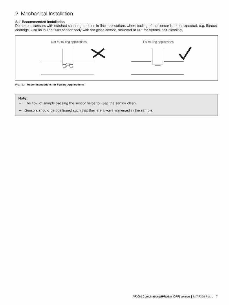
2 Mechanical Installation2.1 Recommended InstallationDo not use sensors with notched sensor guards on in-line applications where fouling of the sensor is to be expected, e.g. fibrous coatings. Use an in-line flush sensor body with flat glass sensor, mounted at 90° for optimal self-cleaning.
Fig. 2.1 Recommendations for Fouling Applications
Note.— The flow of sample passing the sensor helps to keep the sensor clean.
— Sensors should be positioned such that they are always immersed in the sample.
������������������������� ����������������������

8 IM/AP300 Rev. J | AP300 | Combination pH/Redox (ORP) sensors
2.1.1 AP301 SensorsInsertion/Flow-through Type
1. Slide the adaptor sensor retaining ring down from the wiredend of the sensor.
2. Lubricate sensor O-rings before insertion. Insert the sensorinto the adaptor and tighten the retaining collar to prevent thesensor from being blown out when the process lines arepressurized.
3. Do not overtighten the threaded sensor adaptor as the innerdiameter of the fitting can be compressed making sensorinsertion or removal impossible. Use PTFE tape or othersealing compounds on the adaptor threads and tighten onlyas tight as necessary to stop leakage around the threads.
4. Sensors are sometimes mounted upright into a tee in a linethat is not full. The sensor can then be suspended above theliquid or may become air-locked. Both occurrences willcause erratic and erroneous measurement. Most of the timethis can prevented by rotating the sensor to ensure that it isfully immersed in the sample.
Immersion Type1. The use of an immersion guard is recommended to protect
the glass sensor.
2. Levels in many tanks, sumps and channels vary. The sensormust be immersed to the lowest representative level toensure the sensor is always immersed in sample.
3. Sensor cables on immersion sensors should be of adequatelength for the BNC to be attached to an extension cableoutside the immersion area.
Warning. Depressurize and drain the process line before inserting or removing the sensor to prevent spillage.
Fig. 2.2 Installing the AP301
��
For horizontal pipe, the preferred mounting position is in the shaded area. Allowable mounting is
anywhere within the full circumference of the pipe.
Flex Conduit and Coupling(Customer Supplied) T.C. Connector (if applicable)
AP301 Sensor with OptionalPVC Immersion Guard Fitted
AP301 Sensor
Optional1 in. NPT Flow Cell(Part No. 7670046)
Male BNCCable
3/4 in. NPT
Optional PPS Threaded Adaptor
Flow
Bulb Glass Flat Glass

AP300 | Combination pH/Redox (ORP) sensors | IM/AP300 Rev. J 9
2.1.2 AP302/3 SensorsInsertion/Flow-through Type1. Process lines must be shut down and depressurized
before inserting or removing sensors.
2. PTFE tape or other sealing compounds must be applied to the sensor threads to prevent leakage. Overtightening the sensor threads may cause internal damage to the sensor.
3. Sensors are sometimes mounted upright into a tee in a line that is not full. The sensor can then be suspended above the liquid or may become air-locked. Both occurrences may cause erratic and erroneous measurement. This can be prevented by rotating the sensor and flow cell to ensure it is fully immersed in the sample.
Immersion Type1. Levels in many tanks, sumps and channels vary. The
sensor must be immersed to the lowest representative level, to ensure it is always immersed in sample.
2. Sensor cables on immersion sensors should be of adequate length for the BNC to be attached to an extension cable outside the immersion area.
Fig. 2.3 Installing the AP302/3
��
T.C. Connector (if applicable)
Male BNC
Cable
Rear of Sensor and Cable to be Sealed in Conduit or Pipe (Customer Supplied)
Conduit (Customer Supplied)
AP302/3 for Immersion Applications
AP302/3 for Flow Applications
3/4 in. Coupling (Customer Supplied)
3/4 in. Flow Cell(Customer Supplied)
Sample Inlet
Sample OutletFor horizontal pipe, the preferred mounting position is in the shaded area. Allowable mounting is
anywhere within the full circumference of the pipe.
Bulb Glass Flat Glass

10 IM/AP300 Rev. J | AP300 | Combination pH/Redox (ORP) sensors
2.1.3 AP304/5 Sensors
To install the AP304/5 Sensor:
1. Fit choice of ball valve onto the process line or vessel.
2. Fit compression fitting onto the ball valve – see Fig. 2.4.
Continued on page 11…
Warning.— To avoid operator injury if the probe ejects to its end
stop, keep a safe distance when releasing the compression fitting.
— Undo the compression fitting slowly as the probe can slide out to its end stop under process pressure.
— It is hard to insert the probe above a process pressure of 80 psi.
— Process pressure must not exceed 6 bar (87 lb in–2) @ 25 °C (77 °F) continuous. Retract sensors during process start-up to prevent damage due to pressure surges or water hammer.
— Insert the sensor only as far as necessary to achieve representative flow. Over-insertion may damage the sensor and/or cause slow response.
— Fully retract the sensor before closing the valve and fully open the valve before inserting the sensor.
Fig. 2.4 Installing the AP304/5 – Ball Valve and Compression Fitting
��
T.C. Connector (if applicable)
Male BNC
Cable
Rear of Sensor and Cable to beSealed in Conduit or Pipe
(Customer Supplied)
1/2 in. PVDF Retainer
Compression Fitting Reducer
11/4 in. Full Port Ball Valve or 11/2 in. Ball Valve
11/2 in. Nipple
Process Line / Vessel
For horizontal pipe, the preferred mounting position is in the shaded area. Allowable mounting is
anywhere within the full circumference of the pipe.
Flat GlassBulb
AP305 – optimize self-cleaning by using flat glass and notched body
Sample Flow
Sample flow through pipe
Bulb

AP300 | Combination pH/Redox (ORP) sensors | IM/AP300 Rev. J 11
3. Measure and record the following distances – see Fig. 2.5:
— outside of pipe/vessel to the reducer at the back end of the valve A.
— length of compression fitting after insertion into the reducer ?B
— pipe/vessel wall thickness C.
— sensor insertion depth D.
4. Add together measurements from step 3 and, measuring from the tip of the sensor, mark off total onto the shaft of the sensor.
5. Insert the sensor into the ball valve. Tighten onto the ball valve on reducer.
6. Open the ball valve fully and gently push the sensor into the valve until the mark made at 4 reaches the compression fitting.
7. Tighten the outer compression joint (manually or using a wrench depending on type of fitting chosen).
8. A mark can also be made distance B from the tip of the probe. This can then be used to tell when the valve can be closed when retracting the probe.
Fig. 2.5 Installing the AP304/5 – Installation Measurements
!"
#
12 IM/AP300 Rev. J | AP300 | Combination pH/Redox (ORP) sensors
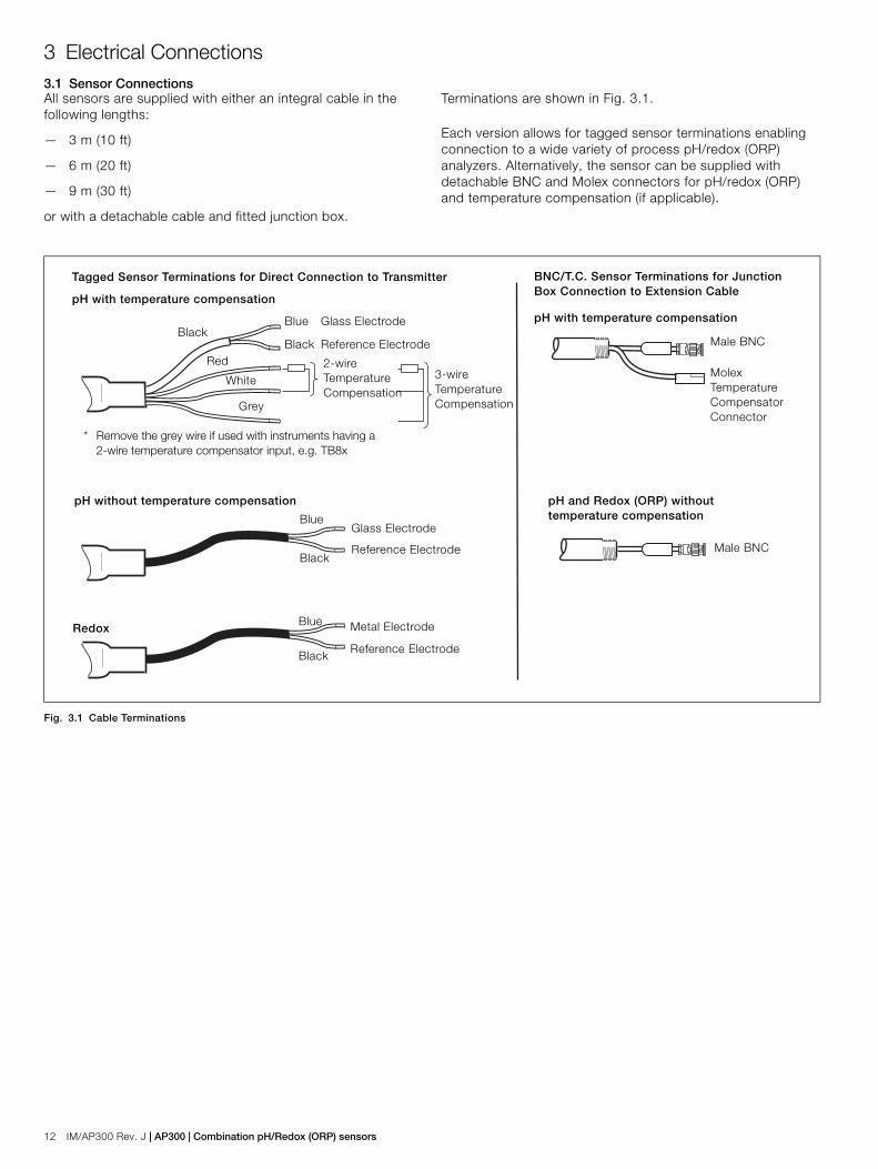
3 Electrical Connections3.1 Sensor ConnectionsAll sensors are supplied with either an integral cable in the following lengths:
— 3 m (10 ft)
— 6 m (20 ft)
— 9 m (30 ft)
or with a detachable cable and fitted junction box.
Terminations are shown in Fig. 3.1.
Each version allows for tagged sensor terminations enabling connection to a wide variety of process pH/redox (ORP) analyzers. Alternatively, the sensor can be supplied with detachable BNC and Molex connectors for pH/redox (ORP) and temperature compensation (if applicable).
Fig. 3.1 Cable Terminations
Tagged Sensor Terminations for Direct Connection to Transmitter
pH with temperature compensation
BNC/T.C. Sensor Terminations for Junction Box Connection to Extension Cable
pH with temperature compensation
Male BNC
Male BNC
pH without temperature compensation pH and Redox (ORP) without temperature compensation
Glass Electrode
Reference Electrode
Metal Electrode
Reference Electrode
Blue
Blue
Black
Black
MolexTemperature Compensator Connector
3-wire Temperature Compensation
2-wire Temperature Compensation
Glass Electrode
Reference Electrode
Blue
BlackBlack
Red
White
Grey
* Remove the grey wire if used with instruments having a 2-wire temperature compensator input, e.g. TB8x
Redox

AP300 | Combination pH/Redox (ORP) sensors | IM/AP300 Rev. J 13
3.2 Extension Cables
Fig. 3.2 Extension Cables
Fig. 3.3 Extension Cables – Typical Installations
Temperature CompensatorConnector
Female BNC to Sensor orJunction Box
pH without temperature compensation
Part numbers: 5 m (16 ft) – 1015 16010 m (32 ft) – 1015 16120 m (64 ft) – 1015 16230 m (96 ft) – 1015 163
Tagged Pin Extension Cable (5-core to AX400)
Conduit(Customer Supplied)
3/4 in. NPT
Junction Box
pH SensorConnections
pH Sensor
Adaptor
1 in. NPT
1 in. Flow Cell(Part No. 7670046)
1 in. Pipe
Flow Application
Sample

14 IM/AP300 Rev. J | AP300 | Combination pH/Redox (ORP) sensors
4 Calibration4.1 pH SensorWhen the sensor has been correctly connected and all electrical connections have been made to the associated pH transmitter, it is ready for calibration by either immersing the sensor (using suitably sized beakers) either:
1. in a calibration solution (buffer) of known pH value for a single-point calibration,
or
2. sequentially in two separate calibration solutions of known pH values for a two point calibration.
For sensors already in use:
1. Remove the electrode from the process or sample.
2. Wash the visible electrode surface with demineralized water.
3. Proceed as described in the paragraph above.
To have agreement with a measured sample, there may be times when a process calibration is necessary.
1. Perform a buffer calibration.
2. Ensure that the sensor is returned to the process for at least 10 minutes before performing a process calibration.
3. To minimize solution temperature effects, measure the sample at the same temperature as the process.
Refer to the instruction manual for the pH transmitter for full details of the calibration procedures.
4.2 Redox (ORP Sensor)When the sensor has been correctly connected and all electrical connections have been made to the associated Redox (ORP) transmitter, it is ready for calibrating. Follow the calibration procedure in the transmitter instruction manual.
For sensors that are connected to transmitters that do not have Redox (ORP) sensor calibration capabilities, it is possible to check the response as follows:
1. Prepare standard 4 and 7 pH buffer solutions. Add one gram (heaped spatula) of analar quinhydrone to 100 ml of each buffer solution. Let them stand for 30 minutes.
2. Immerse the sensor in each solution in turn and note the mV value when stable.
The values obtained should be within ±15 mV of the values below:
Warning. Before removing a sensor from a flow line,ensure that all isolating valves have been closed.
Caution. It is important when buffering to ensure that thevisible surfaces of the electrodes have been cleaned usingdemineralized water. Also ensure when moving from onebuffer solution to the next to wash the electrodes and drythem carefully using a soft tissue.
pH Buffer mV
4 +259
7 +82

AP300 | Combination pH/Redox (ORP) sensors | IM/AP300 Rev. J 15
5 Maintenance5.1 General Cleaning
To ensure accurate monitoring, keep the sensor free of contaminants by periodic cleaning, the frequency of which depends on the particular application.
Methods of removing various types of deposit are detailed below. Replace the sensor if its performance does not improve after cleaning.
5.1.1 General Sludge and Loosely Adhering MatterRinse off the excess matter and wipe the sensor with a soft cloth or tissue before calibrating.
5.1.2 Heavy, Non-Greasy DepositsFor example: lime, salts, etc. Immerse the sensor in 1 to 2 M hydrochloric acid until the deposit has dissolved. Rinse the sensor with water and allow to settle in buffer solution before calibrating.
5.1.3 Greasy or Organic DepositsWipe the glass membrane with a detergent or acetone-based solvent. Rinse with water before calibrating.
5.2 Fault FindingListed below are some common symptoms of sensor malfunction together with possible cures.
Short scaling (Low Slope) or sluggish response1. Glass sensor membrane dirty or coated – refer to Section
5.1 for cleaning.
2. Poor insulation on cable connectors, possibly due to moisture – dry connectors with warm air.
Replace the sensor if no improvement is seen. It may also be necessary to replace the extension cable if used.
No response to pH buffer or sample1. Check the sensor has been correctly wired to the
transmitter as detailed in Section 3.1, page 12 and the relevant transmitter instruction manual.
2. Check the glass sensor membrane is not broken or cracked.
Unstable readings or drift1. Check the sensor has been correctly wired to the
transmitter as detailed in Section 3.1, page 12 and the relevant transmitter instruction manual.
2. Dry or dirty reference junction – clean the junction as detailed in Section 5.1.
Replace the sensor if no improvement.
Stable but incorrect readings1. Recalibrate using fresh buffer solutions.
2. Check temperature compensation settings are correct – manual temperature is correct, or automatic temperature compensation is reading correctly.
3. If the sensor responds correctly to pH changes, but there is an offset of <1.0 pH to >0.2 pH, perform a one-point process calibration (see Section 4.1, page 14).
5.3 Storage of the Electrode
If it is necessary to remove the electrode from the sample line, fill the retained protective cap with buffer solution and cotton wool, or equivalent, and fit it to the sensor.
Warning. Before removing a sensor from a flow line,ensure that all isolating valves have been closed.
Note. All the above symptoms could be caused by afaulty extension cable. Check and replace it, if necessary.
Caution. Failure to ensure that the glass membrane andreference junction do not dry out may irreversibly affect theresponse of the electrode.

16 IM/AP300 Rev. J | AP300 | Combination pH/Redox (ORP) sensors
6 Spares and Accessories
Flow Cells
Pipeline Adapters
Extension Cables
Buffer (Box of 25)
Buffer (Mixed Box of 30)
Threaded lock-nut adapter, PPS (Ryton)(1 in. NPT)
4TB9515-0120
PVC Immersion/Dip Guard 4TB5205-0120
Junction box (requires cable gland) 4TB5023-0162
Cable gland 4TB9515-0244
1 in. NPT (for adapter) + 1 in. NPT (for process connection)
7670 046
1 in. NPT (for adapter) + 1 in. BSPT (for process connection)
7670 043
1 in. BSPT to 1/2 in. BSPT polypropylene 7601 420
1 in. BSPT to 1/2 in. NPT polypropylene 7601 430
Tagged pin extension cables (5-core1015/16X for AX460 and AX466)
5 m (16 ft)10 m (32 ft)20 m (64 ft)30 m (96 ft)
1015 1601015 1611015 1621015 163
4 pH 0400/110
7 pH 0400/120
9 pH 0400/130
4, 7 and 9 pH 0400/135

AP300 | Combination pH/Redox (ORP) sensors | IM/AP300 Rev. J 17
7 SpecificationGeneralpH measuring range
Redox (ORP) measuring range–2000 to 2000 mV
Temperature range
Pressure maximum6 bar (90 psi) @ 25 °C (77 °F)
Temperature compensator (pH sensors only)Integral Pt100 or Balco 3 k
Wetted materials
pH glass types
Reference systemAg/AgCl-3.5M KCl in gel matrix
Reference junctionPorous PTFE
DS/AP300-EN Rev. I
Standard (yellow glass) 0 to 14 pH
Low temperature (blue glass) 0 to 10 pH
Body 0 to 105 °C (32 to 221 °F)
Bulb glass 0 to 105 °C (32 to 221 °F)
Flat glass 5 to 100 °C (41 to 212 °F)
Blue glass –5 to 60 °C (23 to 140 °F)
Redox (ORP) 0 to 105 °C (32 to 221 °F)
pH electrode Glass
Redox (ORP) electrode Platinum
Junction PTFE
Body AP301 PPS (Ryton)
Body AP302/3 and AP304/5 PVDF (Kynar)
Flow cell PVC
Immersion guard PVC
AP304 and AP305 shaft and valve Stainless steel
Bulb general duties
Flat in-line, self-cleaning
Blue low temperature

18 IM/AP300 Rev. J | AP300 | Combination pH/Redox (ORP) sensors
Notes

AP300 | Combination pH/Redox (ORP) sensors | IM/AP300 Rev. J 19

IM/A
P30
0 R
ev. J
0
1.20
18
—ABB LimitedMeasurement & AnalyticsOldends Lane, Stonehouse Gloucestershire, GL10 3TA UKTel: +44 (0)1453 826 661Fax: +44 (0)1453 829 671Mail: [email protected]
ABB Inc.Measurement & Analytics125 E. County Line RoadWarminster, PA 18974USATel: +1 215 674 6000Fax: +1 215 674 7183
abb.com/measurement
—We reserve the right to make technical changes or modify the contents of this document without prior notice. With regard to purchase orders, the agreed particulars shall prevail. ABB does not accept any responsibility whatsoever for potential errors or possible lack of information in this document.
We reserve all rights in this document and in the subject matter and illustrations contained therein. Any reproduction, disclosure to third parties or utilization of its contents – in whole or in parts – is forbidden without prior written consent of ABB.
© Copyright 2018 ABB.All rights reserved.