ANTARES - Lombart Instrument
52
1/174 ANTARES Corneal topographer INSTRUCTIONS FOR USE S4OPTIK, LLC 250 Cooper Ave., Suite 100 Tonawanda, NY, 14150 +1-888-224-6012 +1 800 313 8696 [email protected] 0051
Transcript of ANTARES - Lombart Instrument
1/174
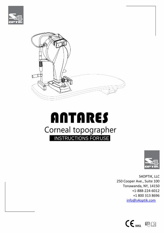
ANTARES Corneal topographer
INSTRUCTIONS FOR USE
S4OPTIK, LLC 250 Cooper Ave., Suite 100
Tonawanda, NY, 14150 +1-888-224-6012 +1 800 313 8696
0051

INSTRUCTIONS FOR USE ANTARES | IFUANTARESEN00
This document is the property of
S4Optik.
Any reproduction, even partial, it is prohibited.
1/48
1 INTRODUCTION ............................................................................. 3 1.1 SYMBOLS ..................................................................................................................... 3
1.1.1 Device symbols ..................................................................................................... 4
1.2 GENERAL WARNINGS .................................................................................................. 4
1.3 NORMATIVE REFERENCES ........................................................................................... 5 1.3.1 Community directives ........................................................................................... 5 1.3.2 Technical standards .............................................................................................. 5 1.3.3 Quality management systems standards.............................................................. 5
1.4 WARRANTY ................................................................................................................. 6 1.5 MANUFACTURER IDENTIFICATION .............................................................................. 7
2 SAFETY ........................................................................................... 8 2.1 SAFETY WARNINGS ...................................................................................................... 8 2.2 DEVICE IDENTIFICATION ............................................................................................ 10
2.2.1 Registration data in the Medical Devices List ..................................................... 10 2.2.2 Device data plate ................................................................................................ 10 2.2.3 Power supply data plate ..................................................................................... 11
2.3 INTENDED USE ........................................................................................................... 11 2.4 MEDICAL DEVICES CLASSIFICATION ........................................................................... 17
2.5 MEDICAL ELECTRICAL DEVICES CLASSIFICATION ....................................................... 17 2.6 ENVIRONMENTAL CONDITIONS ................................................................................. 18 2.7 DISPOSAL AT THE END THE USEFUL LIFE .................................................................... 19 2.8 MANUFACTURER DECLARATIONS ............................................................................. 21
2.8.1 Electromagnetic emissions ................................................................................. 21
3 DEVICE DESCRIPTION .................................................................. 24 3.1 PROVISION DESCRIPTION .......................................................................................... 24
3.1.1 Device ANTARES ................................................................................................. 26 3.1.2 Power supply ...................................................................................................... 27 3.1.3 Chin rest ............................................................................................................. 28 3.1.4 Electric table (optional) ...................................................................................... 29
3.2 TECHNICAL DATA ....................................................................................................... 29
4 DEVICE USE ................................................................................. 31 4.1 HOW TO INSTALL THE DEVICE ................................................................................... 31 4.2 HOW TO CONNECT THE DEVICE................................................................................. 33 4.3 HOW TO PLACE THE ELECTRIC CABLES ...................................................................... 35 4.4 HOW TO TURN ON THE DEVICE ................................................................................. 36 4.5 ADJUST THE CHIN REST .............................................................................................. 37 4.6 HOW TO CAPTURE THE IMAGE .................................................................................. 39
4.7 HOW TO CHANGE THE PAPER FOR CHIN CUP ............................................................ 41 4.8 HOW TO TURN OFF THE DEVICE ................................................................................ 42
5 ORDINARY MAINTENANCE .......................................................... 43 5.1 SAFETY WARNINGS .................................................................................................... 43
5.2 DEVICE CLEANING ...................................................................................................................... 43
INSTRUCTIONS FOR USE ANTARES | IFUANTARESEN00
This document is the property of
S4Optik.
Any reproduction, even partial, it is prohibited.
2/48
5.3 SPARE PARTS AND ACCESSORIES LIST ......................................................................................... 44 5.4 TROUBLESHOOTING ................................................................................................................... 45
INSTRUCTIONS FOR USE ANTARES | IFUANTARESEN00
This document is the property of
S4Optik.
Any reproduction, even partial, it is prohibited.
3/48
1 INTRODUCTION
The device is the result of a long research period, conducted by experts to give the product technical innovation, quality and design. The device can be easily used thanks to the guided manual capture and the electronic control of all the functions of the device.
1.1 SYMBOLS
Within the instructions for use, on the package or on the device, there can be the following symbols:
Symbol Meaning
Caution
Warning, electricity
Read the instructions for use
General mandatory action sign
Note. Useful information for the user
General prohibition sign
Manufacturer
CE Marking (Directive 93/42/EEC) Identification number of the notified body (IMQ)
INSTRUCTIONS FOR USE ANTARES | IFUANTARESEN00
This document is the property of
S4Optik.
Any reproduction, even partial, it is prohibited.
4/48
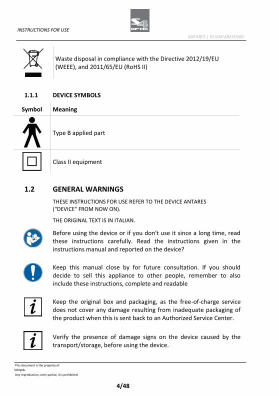
Waste disposal in compliance with the Directive 2012/19/EU (WEEE), and 2011/65/EU (RoHS II)
1.1.1 DEVICE SYMBOLS
1.2 GENERAL WARNINGS
THESE INSTRUCTIONS FOR USE REFER TO THE DEVICE ANTARES ("DEVICE" FROM NOW ON).
THE ORIGINAL TEXT IS IN ITALIAN.
Before using the device or if you don't use it since a long time, read these instructions carefully. Read the instructions given in the instructions manual and reported on the device?
Keep this manual close by for future consultation. If you should decide to sell this appliance to other people, remember to also include these instructions, complete and readable
Keep the original box and packaging, as the free-of-charge service does not cover any damage resulting from inadequate packaging of the product when this is sent back to an Authorized Service Center.
Verify the presence of damage signs on the device caused by the transport/storage, before using the device.
Symbol Meaning
Type B applied part
Class II equipment

INSTRUCTIONS FOR USE ANTARES | IFUANTARESEN00
This document is the property of
S4Optik.
Any reproduction, even partial, it is prohibited.
5/48
It is forbidden to reproduce, totally or partially, texts or images contained in these instructions for use without the written authorization of the Manufacturer.
The Manufacturer reserves himself the right to modify the contents of the instructions for use, without notice.
1.3 NORMATIVE REFERENCES
1.3.1 COMMUNITY DIRECTIVES
- Directive 93/42/EEC and subsequent modifications and integrations concerning medical devices
- Directive 2012/19/EU on waste electrical and electronic equipment (WEEE)
1.3.2 TECHNICAL STANDARDS
- IEC 60601-1: 2005 + A1:2012 - Medical electrical equipment - Part 1: General requirements for basic safety and essential performance
- EC 60601-1-2:2014 Edition 4 Collateral Standard: Electromagnetic disturbances - Requirements and tests
- UNI EN ISO 15004-1:2009 Ophthalmic Instruments. Fundamental requirements and test methods - Part 1: General requirements applicable to all ophthalmic instruments
- UNI EN ISO 15004-2:2007 Ophthalmic Instruments. Fundamental requirements and test methods - Part 2: Light hazard protection
- UNI CEI EN ISO 14971:2012 Medical devices. Application of risk management to medical devices.
- UNI EN ISO 19980:2012 - Ophthalmic instruments - Corneal topographers
1.3.3 QUALITY MANAGEMENT SYSTEMS STANDARDS
- UNI CEI EN ISO 13845:2016 Medical devices. Quality management systems - Requirements for regulatory purposes
INSTRUCTIONS FOR USE ANTARES | IFUANTARESEN00
This document is the property of
S4Optik.
Any reproduction, even partial, it is prohibited.
6/48
1.4 WARRANTY
The Manufacturer is responsible for the device conformity to the Community directive 93/42/EEC as amended by the 2007/47/EC for:
- features - safety and reliability - CE marking
The Manufacturer refuses any responsibility for:
- installation and activation not activated in conformity to the indications and the precautions reported in the instructions for use
- use not in compliance with the instructions for use and precautions reported in the instructions for use
- use of accessories or spare parts not provided or suggested by the Manufacturer
- repairs and safety controls not effectuated by expert, qualified, trained and personnel authorized by the Manufacturer
- electrical system of the space where the device is installed not in compliance with the technical standards, the laws and regulations in effect in the country of installation of the device
- direct or indirect consequences or damages to objects or persons, originating from the improper use of the device or erroneous clinical analysis originating from its use
The Manufacturer guarantees the device for 24 months after invoicing The Warranty includes the substitution, at the Manufacturer's or an Authorized Service Center, of components and materials and the relative labor. The shipping and transport fees are to be paid by the client. The warranty does not cover:
- reparations of faults originating from natural disasters, mechanical shocks (fall, hit, etc), electrical system faults, negligence, improper use, maintenance or reparations carried out with non-original materials
- any other improper use or not intended by the Manufacturer - damages caused by service lack or inefficiency, originating by
causes or circumstances out of the Manufacturers control
INSTRUCTIONS FOR USE ANTARES | IFUANTARESEN00
This document is the property of
S4Optik.
Any reproduction, even partial, it is prohibited.
7/48
- the parts subject to usage and/or deterioration originating from the normal use and those that might be broken because of an improper use or maintenance carried out by personnel non- authorized by the Manufacturer.
To ask maintenance interventions or to have technical information about the device, address to an Authorized Service Center or directly to the device Manufacturer.
The client will not be refunded for damages originating from the device halt.
1.5 MANUFACTURER IDENTIFICATION S4OPTIK, LLC 250 Cooper Ave., Suite 100 Tonawanda, NY, 14150 +1-888-224-6012 +1 800 313 8696 [email protected] https://s4optik.com/
INSTRUCTIONS FOR USE ANTARES | IFUANTARESEN00
This document is the property of
S4Optik.
Any reproduction, even partial, it is prohibited.
8/48
2 SAFETY
2.1 SAFETY WARNINGS
DANGER Electric shock danger. Do not let water fall on the device. Do not immerse the device in water or other liquids.
DANGER Electric shock danger. If the power cables are damaged they must be replaced in an Authorized Service Center to prevent any risk.
DANGER Electric shock danger. Unplug the power cable from the mains socket before disinfecting the device and before any maintenance operation.
CAUTION Do not use the device if visibly damaged. Periodically inspect the device and the connection cables to verify if there are damage signs.
CAUTION Always keep the device out of the reach of children.
CAUTION Danger of device fall. Do not leave free cables which can represent an obstacle or a danger for the patient or the operator.
CAUTION Danger of stumbling and falling. Do not let the power cord or the connection cables free in a place where people could walk.
INSTRUCTIONS FOR USE ANTARES | IFUANTARESEN00
This document is the property of
S4Optik.
Any reproduction, even partial, it is prohibited.
9/48
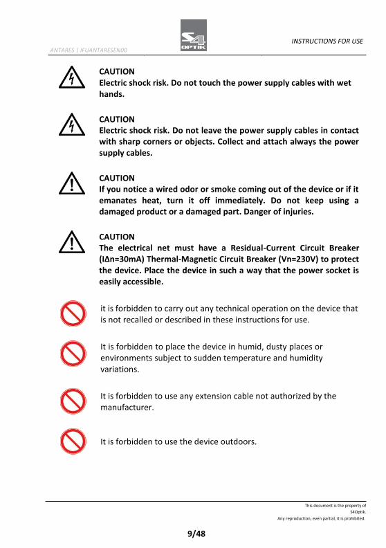
CAUTION Electric shock risk. Do not touch the power supply cables with wet hands.
CAUTION Electric shock risk. Do not leave the power supply cables in contact with sharp corners or objects. Collect and attach always the power supply cables.
CAUTION If you notice a wired odor or smoke coming out of the device or if it emanates heat, turn it off immediately. Do not keep using a damaged product or a damaged part. Danger of injuries.
CAUTION The electrical net must have a Residual-Current Circuit Breaker (IΔn=30mA) Thermal-Magnetic Circuit Breaker (Vn=230V) to protect the device. Place the device in such a way that the power socket is easily accessible.
it is forbidden to carry out any technical operation on the device that is not recalled or described in these instructions for use.
It is forbidden to place the device in humid, dusty places or environments subject to sudden temperature and humidity variations.
It is forbidden to use any extension cable not authorized by the manufacturer.
It is forbidden to use the device outdoors.
INSTRUCTIONS FOR USE ANTARES | IFUANTARESEN00
This document is the property of
S4Optik.
Any reproduction, even partial, it is prohibited.
10/48
The device does not generate and does not receive any electromagnetic interference if it is placed near other electrical appliances. No preventive or corrective actions are required.
2.2 DEVICE IDENTIFICATION
2.2.1 REGISTRATION DATA IN THE MEDICAL DEVICES LIST
CND (national medical devices classification)
Repertoire number (progressive system number attributed to the device)
Market release date
The device registration data can be verified on the Ministero della Salute website on this page: Ministero della Salute - Ricerca dispositivi
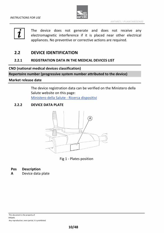
2.2.2 DEVICE DATA PLATE
Fig 1 - Plates position
Pos Description A Device data plate

INSTRUCTIONS FOR USE ANTARES | IFUANTARESEN00
This document is the property of
S4Optik.
Any reproduction, even partial, it is prohibited.
11/48
Fig 2 - Device data plate
2.2.3 POWER SUPPLY DATA PLATE
Fig 3 - Power supply PSP2402 data plate
2.3 INTENDED USE
ANTARES Corneal topographer is an electro-medical device used to perform the corneal topography and for the diagnostic of the lacrimal dysfunction. The device has been designed for the capture and the elaboration of an image of the cornea in the ophthalmic procedure. Thanks to the high resolution color video camera, you can film "live" the corneal surface and visualize it on the computer screen.

INSTRUCTIONS FOR USE ANTARES | IFUANTARESEN00
This document is the property of
S4Optik.
Any reproduction, even partial, it is prohibited.
12/48
The device provides information on the curvature, the elevation and the refractive power, and a great number of concise parameters for the diagnostic and the follow-up of the corneal surface.
Corneal topography
The device provides information on elevation, curvature and dioptric power of the anterior corneal surfaces over a diameter of 10 mm. In addiction to the diagnostic of the corneal anterior surface, the most common application fields are the simulation and the application of corneal contact lenses, the analysis of the tear film dysfunctions, of the meibomian glands, and the keratokonus screening.
Pupillography
The pupillography module is completely integrated with the topography and allows to:
- Perform the pupillometry measurement in scotopic light condition in order to evaluate the maximal pupil extension and the optic zone dimension that has to be set for a treatment.
- Perform the pupillometry measurement in scotopic light condition (0.04 lux).
- Perform the pupillometry measurement in mesopic light condition (4 lux).
- Perform the pupillometry measurement in photopic light condition (50 lux).
- Perform the dynamic pupillometry measurement, starting form 400 lux and turning off the luminous source so that the pupil dilates to its maximal extension.
- Evaluate the pupillary decentralization with respect to the corneal vertex for each of the conditions described above and the pupillary center deviation during the dilatation.
INSTRUCTIONS FOR USE ANTARES | IFUANTARESEN00
This document is the property of
S4Optik.
Any reproduction, even partial, it is prohibited.
13/48
Meibography
The device allows to analyze the Meibomian glands in a non-invasive method. The miebography is performed through the infrared illumination which enhance the contrast, magnifying the anatomic structure of the glands without causing any discomfort to the patient.
Analysis of the tear film
The Placido's disk allows the advanced analysis of the tear film and the evaluation of the NI-BUT (Non Invasive Break-up Time).
Videokeratoscopy
The device is provided with a luminous source with white light for the capture of color images and videos. The luminous source with cobalt blue light allows the analysis of the clearance of rigid contact lenses in fluorescein. Moreover, the device allows the change of magnification for the capture of images with wide field of the tear meniscus and redness of the eye.
Keratoconus screening
An efficient keratoconous screening system, clinically validated, based on a self-learning system, provides suggestions on the risk underlining the cases which have a greater possibility of complications.
Module for contact lenses application.
The module for the application of contact lenses application allows to perform the simulation of rigid contact lenses thanks to a wide database of models and international manufacturers.
More features of the device with the application software
The device, with the application software allows:
- Guided manual capture - Management of the patients data and possibility to effectuate
personalized researches and statistics
INSTRUCTIONS FOR USE ANTARES | IFUANTARESEN00
This document is the property of
S4Optik.
Any reproduction, even partial, it is prohibited.
14/48
- Advanced editing system of the rings which allows to modify the position of the edges in order to provide a proper reconstruction even on distorted surfaces.
- Availability of the following maps: sagittal curvature map, tangential curvature map, elevation, refractive power, Gaussian curvature map, corneal thickness.
- Screens and summaries which allow to personalize the device depending on the user:
- Four maps summary - Single map screen - Keratoconus summary - Six maps summary
- Advanced altimetry and Zernike summary - Corneal wavefront analysis with setting of the pupil, it
includes the maps of the most common aberrations - Corneal wavefront analysis with summary of visual quality
referred tho the anterior corneal face with PSF, Spot Diagram, MTF and vision simulation for the analyzed wavefront
- Tools for the follow-up control with differential maps with 2 or 3 elements
- Tools for the follow-up control with comparison between 4 different maps
- A wide series of concise descriptors of the features of the cornea, such as:
- Autofit for the research of the best contact lens based on the altimetric elevation measure of the cornea, on a database of more than 50.000 lenses
- Possibility to personalize the contact lens and to simulate its application
- Sim-K to simulate the measurement of an ophtalmoscope with fixed targets (for the anterior surface)
- Principal corneal meridians in the zones of 3 mm, 5 mm and 7 mm
- Flatter and steeper hemimeridians in the zones of 3 mm, 5 mm and 7 mm
INSTRUCTIONS FOR USE ANTARES | IFUANTARESEN00
This document is the property of
S4Optik.
Any reproduction, even partial, it is prohibited.
15/48
- Peripheral degrees - Pupil decentralization, pupil diameter, and corneal diameter
size - Keratorefractive indices calculated in the pupil area for an
evaluation of the patient's visual quality - Keratoconus screening index for diagnosis and follow-up
The device must be used only by practitioners, within the limits of the law and the regulations for the exercise of the profession. The device must be used in combination with a PC and the application software Phoenix. System minimum requirements
- PC: 4 GB RAM - Video Card 1 GB RAM (not shared) resolution 1024 x 768 pixels
- Operating system: Windows XP, Windows 7 and Windows 10 (32/64 bit).
Read the instructions for use of the application software.
The PC must be compliant to the norm IEC 60950-1 Information technology equipment - Safety - Part 1: General requirements. If the PC is installed in the patient area it is necessary to install an isolation electrical supply compliant with the directive IEC 60601- 1:2005 + A1:2012- "Medical electrical equipment - Part 1: General requirements for basic safety and essential performance".
It is possible to connect other accessories to the PC (printer, modem, scanner, etc) through the analogical or digital interfaces. The accessories (printer, modem, scanner, etc) must be installed outside the patient area.
INSTRUCTIONS FOR USE ANTARES | IFUANTARESEN00
This document is the property of
S4Optik.
Any reproduction, even partial, it is prohibited.
16/48
The accessories must be compliant to the norm IEC 60950-1 Information technology equipment - Safety - Part 1: General requirements. If the accessories are installed in the patient area it is necessary to install an isolation electrical supply compliant with the directive IEC 60601-1:2005 + A1:2102 - "Medical electrical equipment - Part 1: General requirements for basic safety and essential performance".
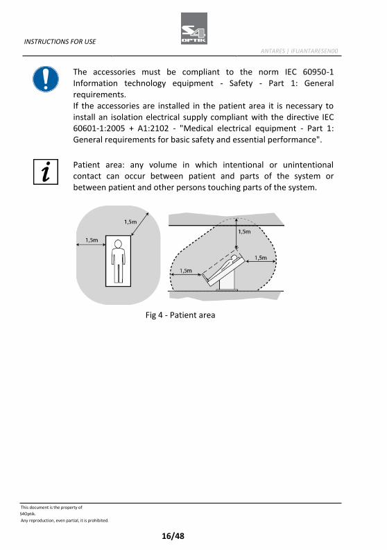
Patient area: any volume in which intentional or unintentional contact can occur between patient and parts of the system or between patient and other persons touching parts of the system.
Fig 4 - Patient area

INSTRUCTIONS FOR USE ANTARES | IFUANTARESEN00
This document is the property of
S4Optik.
Any reproduction, even partial, it is prohibited.
17/48
2.4 MEDICAL DEVICES CLASSIFICATION
Technical data Value
Classification in compliance with the attached IX to the Directive 93/42/EEC and subsequent modifications
Class Im
2.5 MEDICAL ELECTRICAL DEVICES CLASSIFICATION
Classification in compliance with the technical specification EN 60601- 1:2005 + A1:2012
Technical data Value
Type of protection against the direct and indirect contacts
Class II
Applied parts Type B
Protection degree against humidity IP20 (no protection against liquid infiltration)
Sterilization or disinfection method This device can be disinfected
Protection degree in presence of anesthetics or inflammable detergents
No protection
Electrical connection degree between device and patient
Appliances with part applied on the patient
Use conditions Continuous functioning
INSTRUCTIONS FOR USE ANTARES | IFUANTARESEN00
This document is the property of
S4Optik.
Any reproduction, even partial, it is prohibited.
18/48
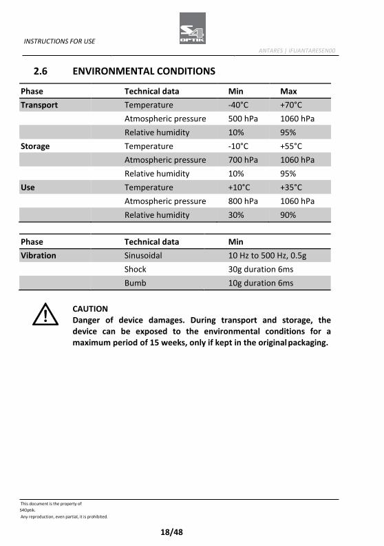
2.6 ENVIRONMENTAL CONDITIONS
Phase Technical data Min Max
Transport Temperature -40°C +70°C
Atmospheric pressure 500 hPa 1060 hPa Relative humidity 10% 95%
Storage Temperature -10°C +55°C Atmospheric pressure 700 hPa 1060 hPa
Relative humidity 10% 95%
Use Temperature +10°C +35°C
Atmospheric pressure 800 hPa 1060 hPa
Relative humidity 30% 90%
Phase Technical data Min
Vibration Sinusoidal 10 Hz to 500 Hz, 0.5g
Shock 30g duration 6ms Bumb 10g duration 6ms
CAUTION Danger of device damages. During transport and storage, the device can be exposed to the environmental conditions for a maximum period of 15 weeks, only if kept in the original packaging.
INSTRUCTIONS FOR USE ANTARES | IFUANTARESEN00
This document is the property of
S4Optik.
Any reproduction, even partial, it is prohibited.
19/48
2.7 DISPOSAL AT THE END THE USEFUL LIFE
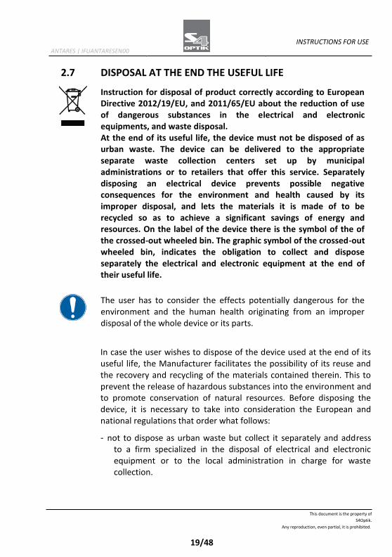
Instruction for disposal of product correctly according to European Directive 2012/19/EU, and 2011/65/EU about the reduction of use of dangerous substances in the electrical and electronic equipments, and waste disposal. At the end of its useful life, the device must not be disposed of as urban waste. The device can be delivered to the appropriate separate waste collection centers set up by municipal administrations or to retailers that offer this service. Separately disposing an electrical device prevents possible negative consequences for the environment and health caused by its improper disposal, and lets the materials it is made of to be recycled so as to achieve a significant savings of energy and resources. On the label of the device there is the symbol of the of the crossed-out wheeled bin. The graphic symbol of the crossed-out wheeled bin, indicates the obligation to collect and dispose separately the electrical and electronic equipment at the end of their useful life.
The user has to consider the effects potentially dangerous for the environment and the human health originating from an improper disposal of the whole device or its parts.
In case the user wishes to dispose of the device used at the end of its useful life, the Manufacturer facilitates the possibility of its reuse and the recovery and recycling of the materials contained therein. This to prevent the release of hazardous substances into the environment and to promote conservation of natural resources. Before disposing the device, it is necessary to take into consideration the European and national regulations that order what follows:
- not to dispose as urban waste but collect it separately and address to a firm specialized in the disposal of electrical and electronic equipment or to the local administration in charge for waste collection.

INSTRUCTIONS FOR USE ANTARES | IFUANTARESEN00
This document is the property of
S4Optik.
Any reproduction, even partial, it is prohibited.
20/48
- in the event that a new device is purchased from the same Manufacturer to replace an old one placed on the market before 13 August 2005, equivalent and with the same functions of the new device, the Distributor or Manufacturer are legally required to collect the old device.
- if the user decides to dispose a used device, put on the market after the 13th August 2005, the Distributor or the Manufacturer have to collect it.
- the Manufacturer takes care, by joining a consortium for the technological devices waste, of the treatment and the recycling of the used device by paying its costs.
The Manufacturer is available to give the user all the information about the dangerous substances contained in the device, and on the recycling modalities of those substances and about the possibility of a reuse of the used device. Strict sanctions for transgressors are provided for by law. For specific information about the disposal in other countries than Italy, contact the local Dealer.

INSTRUCTIONS FOR USE ANTARES | IFUANTARESEN00
This document is the property of
S4Optik.
Any reproduction, even partial, it is prohibited.
21/48
2.8 MANUFACTURER DECLARATIONS
2.8.1 ELECTROMAGNETIC EMISSIONS
The device is designed to be used in a room with the following electromagnetic characteristics:
Emission test Compliance Electromagnetic environment
Radio frequency emission. CISPR 11
Group 1
The device uses radio frequency energy only for its inner functioning. The radio frequency emissions of the device are very low and should not cause interferences with the near appliances.
Radio frequency emission. CISPR 11
Class B
The device can be used in all the environments, included the domestic environment. The device can be connected directly to a low tension power supply net as there is in the housing units.
Harmonic emissions. IEC 61000-3-2
Class A
The device can be used in all the environments, included the domestic environment. The device can be connected directly to a low tension power supply net as there is in the housing units.
Limitation of voltage changes, voltage fluctuations and flicker. IEC 61000-3-3
Compliant
The device can be used in all the environments, included the domestic environment. The device can be connected directly to a low tension power supply net as there is in the housing units.
INSTRUCTIONS FOR USE ANTARES | IFUANTARESEN00
This document is the property of
S4Optik.
Any reproduction, even partial, it is prohibited.
22/48
Immunity test IEC 60601-1-2 test level
Conformity level
Electromagnetic environment
Electrostatic discharge. IEC 61000-4-2
±6 kV contact. ±8 kV air
±6 kV contact. ±8 kV air
Floors should be wood, concrete or ceramic tile. If the floors are covered with synthetic material the relative humidity should be at least 30%.
Electrical fast transient/burst. IEC 61000-4-4
±2 kV for power supply lines. ±1 kV for input/output lines
±2 kV for power supply lines. Non- applicable
Mains power quality shall be that of a typical commercial or hospital environment.
Surge IEC 61000- 4-5
±1 kV differential mode. ±2 kV common mode
±1 kV differential mode. ±2 kV common mode
Mains power quality shall be that of a typical commercial or hospital environment.
Voltage dips. Short interruptions and voltage variations on power supply input lines. IEC 61000-4-11
<5% Un for 0.5 cycles. 40% Un for 5 cycles. 70% Un for 25 cycles. <5% Un for 5 s
<5% Un for 0.5 cycles. 40% Un for 5 cycles. 70% Un for 25 cycles. <5% Un for 5 s
Mains power quality shall be that of a typical commercial or hospital environment. If the user of the device requires continued operation during power mains interruptions, it is recommended that the device is powered from an uninterrupted power supply or battery.
Power frequency (50/60Hz) magnetic fields. IEC 61000-4-8
3 A/m
3 A/m
Power frequency of the magnetic fields should be that of a typical commercial or hospital environment.
This document is the property of
S4Optik.
Any reproduction, even partial, it is prohibited.
23/48
INSTRUCTIONS FOR USE ANTARES | IFUANTARESEN00
Immunity test
IEC 60601-1-2 test level
Conformity level
Electromagnetic environment
RF conduced IEC 61000-4-6 RF conduced IEC 61000-4-3
3 Vrms from 150 kHz to 80 MHz 3 V/m from 80 MHz to 2.5 GHz
3 Vrms 3 V/m
(1)
(1) Portable and mobile RF communication equipment should be used no closer to any part of the device, including cables, than the recommended separation distance calculated from the equation applicable to the frequency of the transmitter. d=1,167*sqrt (P) d=1,167*sqrt (P) 80 MHz to 800 MHz d=2,333*sqrt (P) 800 MHz to 2,5 GHz P: is the maximum output power rating of the transmitter in watts (W) according to the transmitter Manufacturer. d: is the recommended distance in metres (m) at which the portable radio frequency (RF) appliances can be used. Field strengths from fixed RF transmitters, as determined by an electromagnetic site survey, should be less than the compliance level in each frequency range. Interference may occur in the vicinity of
equipment marked with the following symbol:
(Un) is the AC mains voltage prior to application of the test level. At 80 MHz and 800 MHz, the higher frequency range applies. These guidelines may not apply in all situations. Electromagnetic propagation is affected by absorption and reflection from structures, objects and people.
This document is the property of
S4Optik.
Any reproduction, even partial, it is prohibited.
24/48
INSTRUCTIONS FOR USE ANTARES | IFUANTARESEN00
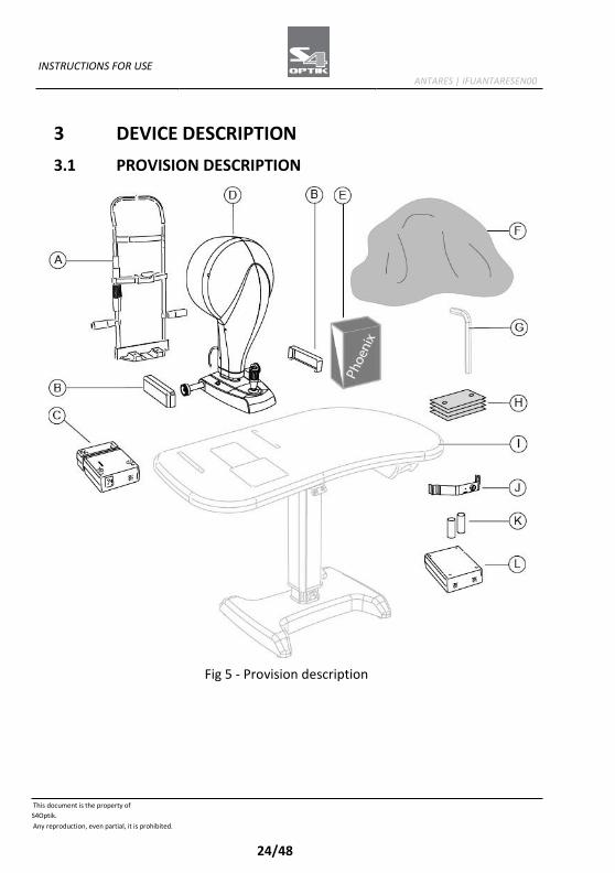
3 DEVICE DESCRIPTION
3.1 PROVISION DESCRIPTION
Fig 5 - Provision description
This document is the property of
S4Optik.
Any reproduction, even partial, it is prohibited.
25/48
INSTRUCTIONS FOR USE ANTARES | IFUANTARESEN00
Pos
Denomination
Description A Chin rest Adjustable height Adjustable distance
between chin and forehead
B Protection carter Protection against accidental hand crushing.
C Power supply
D Device ANTARES Composed by a camera unit equipped with one or several micro video cameras for capturing the images. USB cable for connection between device and computer.
E Application software
Application software for image capture and device management.
F Protective cover optional Place on the device when it is not in use to protect it from dust.
G Set of hex keys with screws
optional
H Package of paper for chin cup
I Electric table optional Adjustable electric support surface with one or two columns. Drawer and auxiliary sockets with fairlead.
J Calibration tool
K 2 fuses
L Isolation transformer
optional 230V/230V for the use of the non electro-medical appliances in the patient area.
For the list of accessories and available models contact the Manufacturer or the local Distributor.
This document is the property of
S4Optik.
Any reproduction, even partial, it is prohibited.
26/48
INSTRUCTIONS FOR USE ANTARES | IFUANTARESEN00
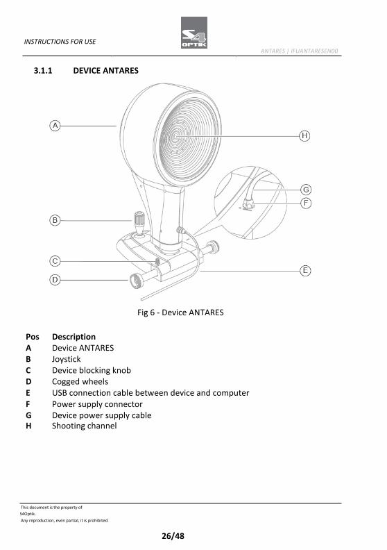
3.1.1 DEVICE ANTARES
Fig 6 - Device ANTARES
Pos Description A Device ANTARES B Joystick C Device blocking knob D Cogged wheels E USB connection cable between device and computer F Power supply connector G Device power supply cable H Shooting channel
This document is the property of
S4Optik.
Any reproduction, even partial, it is prohibited.
27/48
INSTRUCTIONS FOR USE ANTARES | IFUANTARESEN00
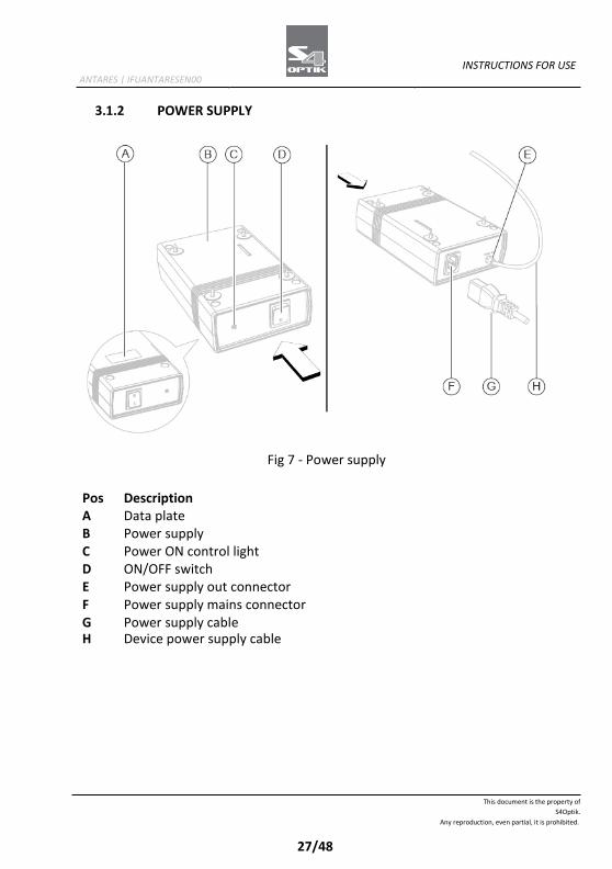
3.1.2 POWER SUPPLY
Fig 7 - Power supply
Pos Description A Data plate B Power supply C Power ON control light D ON/OFF switch E Power supply out connector F Power supply mains connector G Power supply cable H Device power supply cable

This document is the property of
S4Optik.
Any reproduction, even partial, it is prohibited.
28/48
INSTRUCTIONS FOR USE ANTARES | IFUANTARESEN00
3.1.3 CHIN REST
Fig 8 - Chin rest
Pos Description A Chin rest support B Handle C Knob D Chin cup E Forehead rest F Chin rest structure
This document is the property of
S4Optik.
Any reproduction, even partial, it is prohibited.
29/48
INSTRUCTIONS FOR USE ANTARES | IFUANTARESEN00
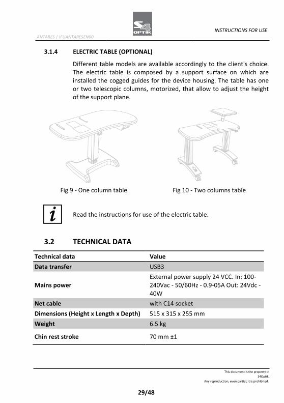
3.1.4 ELECTRIC TABLE (OPTIONAL)
Different table models are available accordingly to the client's choice. The electric table is composed by a support surface on which are installed the cogged guides for the device housing. The table has one or two telescopic columns, motorized, that allow to adjust the height of the support plane.
Fig 9 - One column table Fig 10 - Two columns table
Read the instructions for use of the electric table.
3.2 TECHNICAL DATA
Technical data Value
Data transfer USB3
Mains power
External power supply 24 VCC. In: 100- 240Vac - 50/60Hz - 0.9-05A Out: 24Vdc - 40W
Net cable with C14 socket
Dimensions (Height x Length x Depth) 515 x 315 x 255 mm
Weight 6.5 kg
Chin rest stroke 70 mm ±1
This document is the property of
S4Optik.
Any reproduction, even partial, it is prohibited.
30/48
INSTRUCTIONS FOR USE ANTARES | IFUANTARESEN00
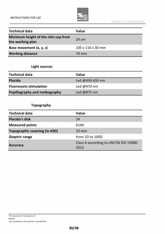
Technical data Value
Minimum height of the chin cup from the working plan
24 cm
Base movement (x, y, z) 105 x 110 x 30 mm
Working distance 74 mm
Light sources
Technical data Value
Placido Led @450-650 nm
Fluorescein stimulation Led @470 nm
Pupillography and meibography Led @875 nm
Topography
Technical data Value
Placido's disk 24
Measured points 6144
Topographic covering (in 43D) 10 mm
Dioptric range from 1D to 100D
Accuracy Class A according to UNI EN ISO 19980- 2012
This document is the property of
S4Optik.
Any reproduction, even partial, it is prohibited.
31/48
INSTRUCTIONS FOR USE ANTARES | IFUANTARESEN00
4 DEVICE USE
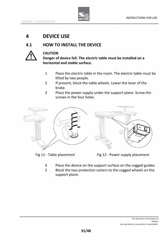
4.1 HOW TO INSTALL THE DEVICE
CAUTION Danger of device fall. The electric table must be installed on a horizontal and stable surface.
1 Place the electric table in the room. The electric table must be
lifted by two people. 2 If present, block the table wheels. Lower the lever of the
brake. 3 Place the power supply under the support plane. Screw the
screws in the four holes.
Fig 11 - Table placement Fig 12 - Power supply placement
4 Place the device on the support surface on the cogged guides. 5 Block the two protection carters to the cogged wheels on the
support plane.
This document is the property of
S4Optik.
Any reproduction, even partial, it is prohibited.
32/48
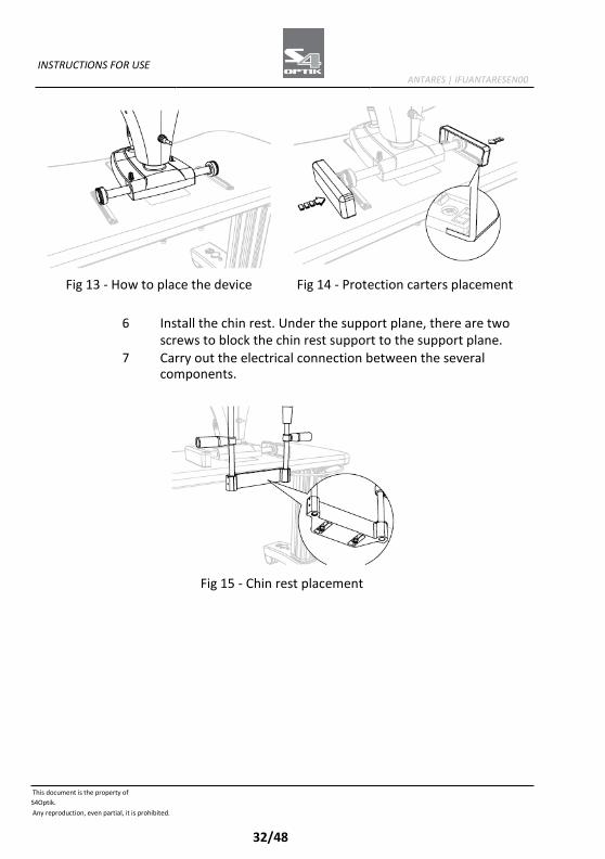
INSTRUCTIONS FOR USE ANTARES | IFUANTARESEN00
Fig 13 - How to place the device Fig 14 - Protection carters placement
6 Install the chin rest. Under the support plane, there are two
screws to block the chin rest support to the support plane. 7 Carry out the electrical connection between the several
components.
Fig 15 - Chin rest placement
This document is the property of
S4Optik.
Any reproduction, even partial, it is prohibited.
33/48
INSTRUCTIONS FOR USE ANTARES | IFUANTARESEN00
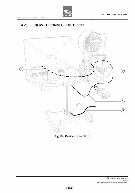
4.2 HOW TO CONNECT THE DEVICE
Fig 16 - Device connection
This document is the property of
S4Optik.
Any reproduction, even partial, it is prohibited.
34/48
INSTRUCTIONS FOR USE ANTARES | IFUANTARESEN00
Pos
Denomination A USB connection cable between device and PC B Power cable for the connection of the electric table with the power
supply
C Power cable for the connection of the electric table with the power supply
D Power cable for the connection between the power supply and the device
This document is the property of
S4Optik.
Any reproduction, even partial, it is prohibited.
35/48
INSTRUCTIONS FOR USE ANTARES | IFUANTARESEN00
4.3 HOW TO PLACE THE ELECTRIC CABLES
CAUTION Danger of device fall. Do not leave free cables which can represent an obstacle or a danger for the patient or the operator.
CAUTION Danger of stumbling and falling. Do not let the power cord or the connection cables free in a place where people could walk.
CAUTION Electric shock risk. Do not leave the power supply cables in contact with sharp corners or objects. Collect and attach always the power supply cables.
It is forbidden to use any extension cable not authorized by the manufacturer.
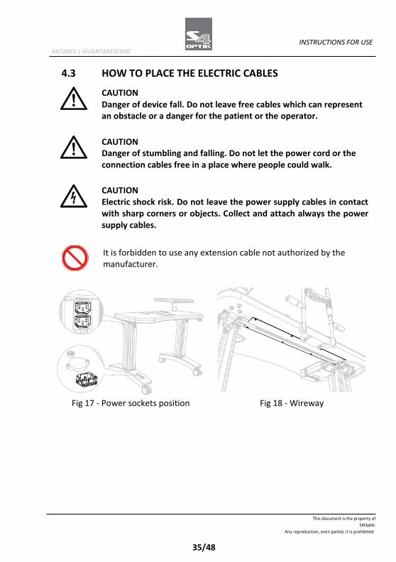
Fig 17 - Power sockets position Fig 18 - Wireway
This document is the property of
S4Optik.
Any reproduction, even partial, it is prohibited.
36/48
INSTRUCTIONS FOR USE ANTARES | IFUANTARESEN00
The power socket is on the column of the electric table, below, and it has to be used for the connection with the mains power. One of the power sockets on the column of the electric table, on top, is dedicated to the device power supply. Block the cables under the support surface with the cable rivets. If you have it, place the cables in the wireway under the support plane.
4.4 HOW TO TURN ON THE DEVICE
1 Turn on the PC. 2 Push the activation switch of the power supply on ON. 3 Launch the application software Phoenix. 4 Wait until the main screen of the application software is
shown. 5 Click on NEW PATIENT and enter his personal data. If the
patient is already present in the database, you can automatically search the surname in the surname command line.
6 A new examination will be created automatically. 7 Select the tool to use. 8 The image capture screen will open. Now it will be possible to
capture the image.
Creation of a new exam
- Click on the button NEW EXAMINATION. - Select the tool to use. - The image capture screen will open. Now it will be possible to
capture the image.
This document is the property of
S4Optik.
Any reproduction, even partial, it is prohibited.
37/48
INSTRUCTIONS FOR USE ANTARES | IFUANTARESEN00
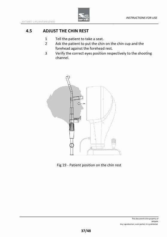
4.5 ADJUST THE CHIN REST
1 Tell the patient to take a seat. 2 Ask the patient to put the chin on the chin cup and the
forehead against the forehead rest. 3 Verify the correct eyes position respectively to the shooting
channel.
Fig 19 - Patient position on the chin rest
This document is the property of
S4Optik.
Any reproduction, even partial, it is prohibited.
38/48
INSTRUCTIONS FOR USE ANTARES | IFUANTARESEN00
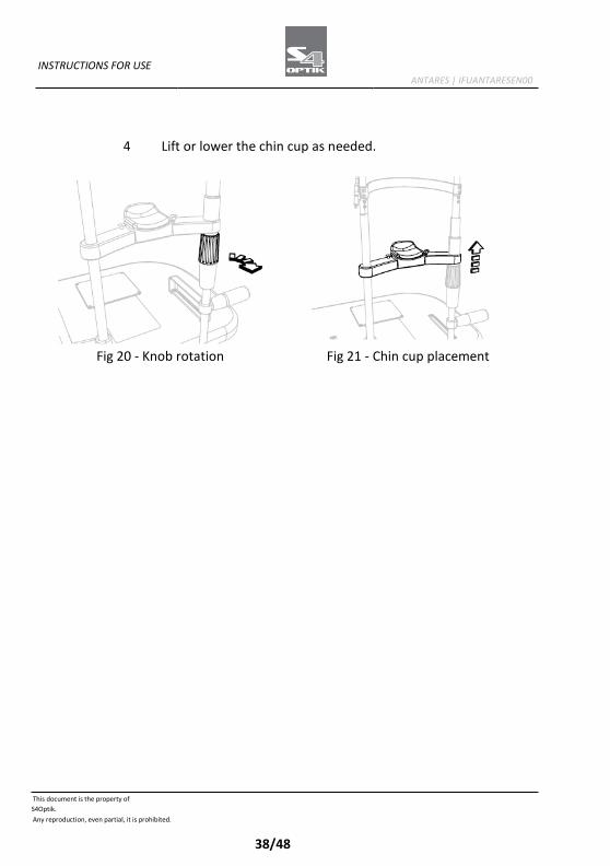
4 Lift or lower the chin cup as needed.
Fig 20 - Knob rotation Fig 21 - Chin cup placement
This document is the property of
S4Optik.
Any reproduction, even partial, it is prohibited.
39/48
INSTRUCTIONS FOR USE ANTARES | IFUANTARESEN00
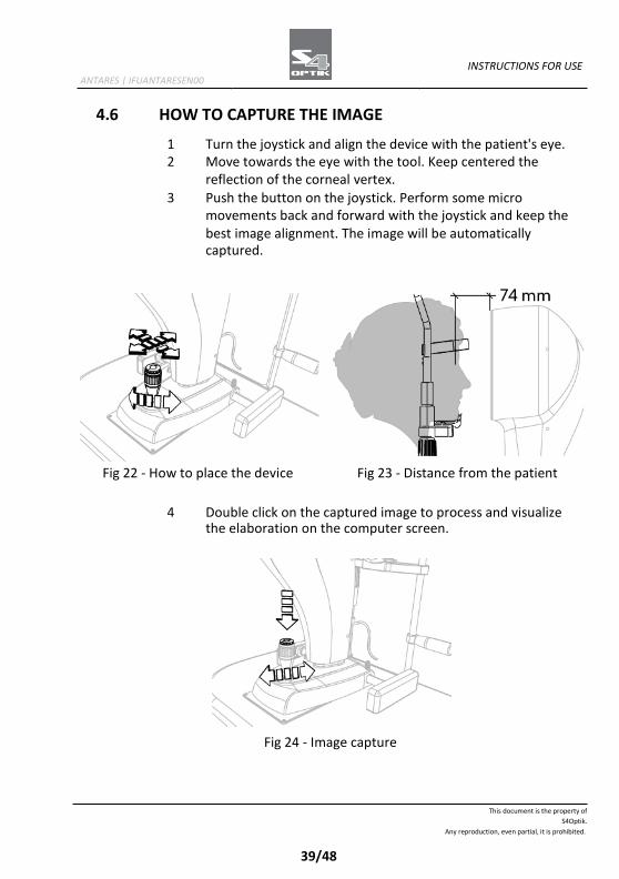
4.6 HOW TO CAPTURE THE IMAGE
1 Turn the joystick and align the device with the patient's eye. 2 Move towards the eye with the tool. Keep centered the
reflection of the corneal vertex.
3 Push the button on the joystick. Perform some micro movements back and forward with the joystick and keep the best image alignment. The image will be automatically captured.
Fig 22 - How to place the device Fig 23 - Distance from the patient
4 Double click on the captured image to process and visualize
the elaboration on the computer screen.
Fig 24 - Image capture
This document is the property of
S4Optik.
Any reproduction, even partial, it is prohibited.
40/48
INSTRUCTIONS FOR USE ANTARES | IFUANTARESEN00
Refer to the application software instructions for the image managing in the database.
This document is the property of
S4Optik.
Any reproduction, even partial, it is prohibited.
41/48
INSTRUCTIONS FOR USE ANTARES | IFUANTARESEN00
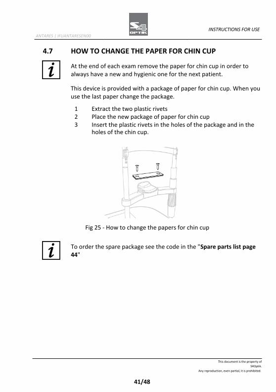
4.7 HOW TO CHANGE THE PAPER FOR CHIN CUP
At the end of each exam remove the paper for chin cup in order to always have a new and hygienic one for the next patient.
This device is provided with a package of paper for chin cup. When you use the last paper change the package.
1 Extract the two plastic rivets 2 Place the new package of paper for chin cup 3 Insert the plastic rivets in the holes of the package and in the
holes of the chin cup.
Fig 25 - How to change the papers for chin cup
To order the spare package see the code in the "Spare parts list page 44"
This document is the property of
S4Optik.
Any reproduction, even partial, it is prohibited.
42/48
INSTRUCTIONS FOR USE ANTARES | IFUANTARESEN00
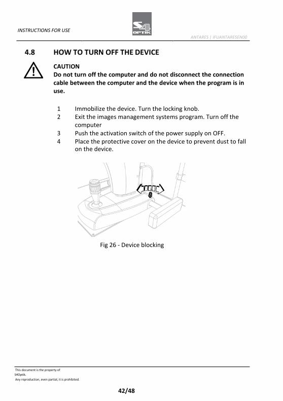
4.8 HOW TO TURN OFF THE DEVICE
CAUTION Do not turn off the computer and do not disconnect the connection cable between the computer and the device when the program is in use.
1 Immobilize the device. Turn the locking knob. 2 Exit the images management systems program. Turn off the
computer 3 Push the activation switch of the power supply on OFF. 4 Place the protective cover on the device to prevent dust to fall
on the device.
Fig 26 - Device blocking
This document is the property of
S4Optik.
Any reproduction, even partial, it is prohibited.
43/48
INSTRUCTIONS FOR USE ANTARES | IFUANTARESEN00
5 ORDINARY MAINTENANCE
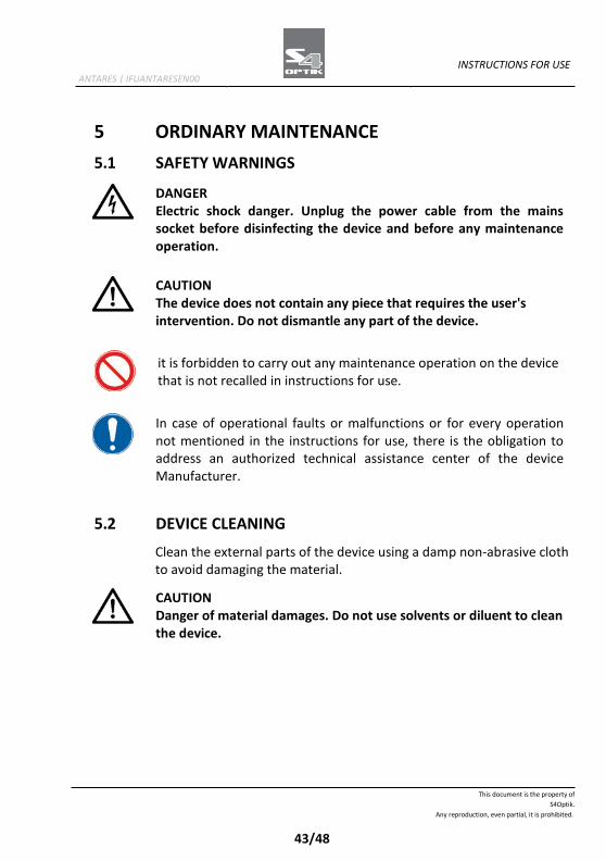
5.1 SAFETY WARNINGS
DANGER Electric shock danger. Unplug the power cable from the mains socket before disinfecting the device and before any maintenance operation.
CAUTION The device does not contain any piece that requires the user's intervention. Do not dismantle any part of the device.
it is forbidden to carry out any maintenance operation on the device that is not recalled in instructions for use.
In case of operational faults or malfunctions or for every operation not mentioned in the instructions for use, there is the obligation to address an authorized technical assistance center of the device Manufacturer.
5.2 DEVICE CLEANING
Clean the external parts of the device using a damp non-abrasive cloth to avoid damaging the material.
CAUTION Danger of material damages. Do not use solvents or diluent to clean the device.
This document is the property of
S4Optik.
Any reproduction, even partial, it is prohibited.
44/48
INSTRUCTIONS FOR USE ANTARES | IFUANTARESEN00
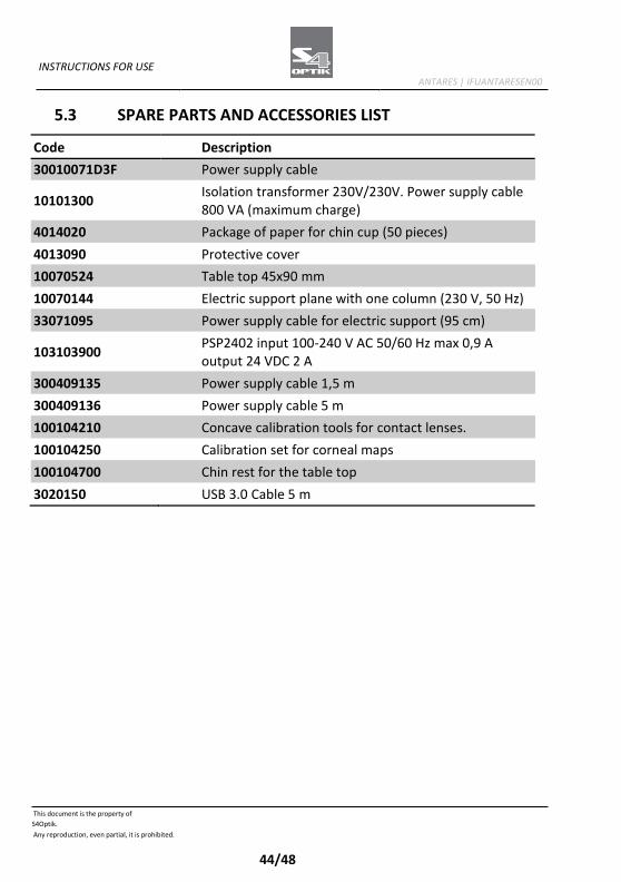
5.3 SPARE PARTS AND ACCESSORIES LIST
Code Description
30010071D3F Power supply cable
10101300 Isolation transformer 230V/230V. Power supply cable 800 VA (maximum charge)
4014020 Package of paper for chin cup (50 pieces)
4013090 Protective cover
10070524 Table top 45x90 mm
10070144 Electric support plane with one column (230 V, 50 Hz)
33071095 Power supply cable for electric support (95 cm)
103103900 PSP2402 input 100-240 V AC 50/60 Hz max 0,9 A output 24 VDC 2 A
300409135 Power supply cable 1,5 m
300409136 Power supply cable 5 m
100104210 Concave calibration tools for contact lenses.
100104250 Calibration set for corneal maps
100104700 Chin rest for the table top
3020150 USB 3.0 Cable 5 m
This document is the property of
S4Optik.
Any reproduction, even partial, it is prohibited.
45/48
INSTRUCTIONS FOR USE ANTARES | IFUANTARESEN00
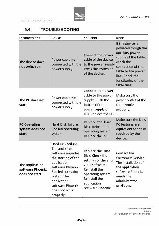
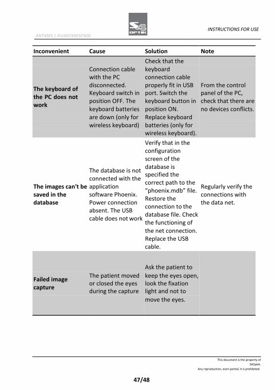
5.4 TROUBLESHOOTING
Inconvenient Cause Solution Note
The device does not switch on
Power cable not connected with the power supply
Connect the power cable of the device to the power supply Press the switch on of the device.
If the device is powered trough the auxiliary power supply of the table, check the connection of the table to the power line. Check the functioning of the table fuses.
The PC does not start
Power cable not connected with the power supply
Connect the power cable to the power supply. Push the button of the power supply on ON. Replace the PC.
Make sure the power outlet of the room works properly.
PC Operating system does not start
Hard Disk failure. Spoiled operating system
Replace the Hard Disk. Reinstall the operating system. Replace the PC.
Make sure the New PC features are equivalent to those required by the device.
The application software Phoenix does not start
Hard Disk failure. The anti virus software impedes the starting of the application software Phoenix. Spoiled operating system The application software Phoenix does not work properly.
Replace the Hard Disk. Check the settings of the anti virus software. Reinstall the operating system. Reinstall the application software Phoenix.
Contact the Customers Service. The installation of the application software Phoenix needs the administrator privileges.
This document is the property of
S4Optik.
Any reproduction, even partial, it is prohibited.
46/48
INSTRUCTIONS FOR USE ANTARES | IFUANTARESEN00
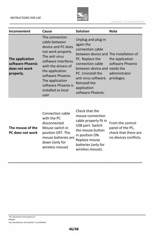
Inconvenient Cause Solution Note
The application software Phoenix does not work properly.
The connection cable between device and PC does not work properly. The anti virus software interferes with the drivers of the application software Phoenix. The application software Phoenix is installed as local user
Unplug and plug in again the connection cable between device and PC. Replace the connection cable between device and PC. Uninstall the anti virus software. Reinstall the application software Phoenix.
The installation of the application software Phoenix needs the administrator privileges.
The mouse of the PC does not work
Connection cable with the PC disconnected. Mouse switch in position OFF. The mouse batteries are down (only for wireless mouse)
Check that the mouse connection cable properly fit in USB port. Switch the mouse button in position ON. Replace mouse batteries (only for wireless mouse).
From the control panel of the PC, check that there are no devices conflicts.
This document is the property of
S4Optik.
Any reproduction, even partial, it is prohibited.
47/48
INSTRUCTIONS FOR USE ANTARES | IFUANTARESEN00
Inconvenient Cause Solution Note
Check that the
Connection cable keyboard
with the PC connection cable
The keyboard of the PC does not work
disconnected. Keyboard switch in position OFF. The keyboard batteries
properly fit in USB port. Switch the keyboard button in position ON.
From the control panel of the PC, check that there are no devices conflicts.
are down (only for Replace keyboard
wireless keyboard) batteries (only for
wireless keyboard).
Verify that in the
configuration
screen of the
The images can't be saved in the database
The database is not connected with the application software Phoenix. Power connection absent. The USB cable does not work
database is specified the correct path to the “phoenix.mdb” file. Restore the connection to the database file. Check the functioning of
Regularly verify the connections with the data net.
the net connection.
Replace the USB
cable.
Ask the patient to
Failed image capture
The patient moved or closed the eyes during the capture
keep the eyes open, look the fixation light and not to
move the eyes.
This document is the property of
S4Optik.
Any reproduction, even partial, it is prohibited.
48/48
INSTRUCTIONS FOR USE ANTARES | IFUANTARESEN00
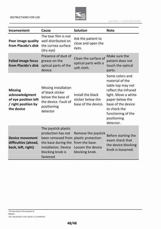
Inconvenient Cause Solution Note
Poor image quality from Placido's disk
The tear film is not well distributed on the cornea surface (dry eye)
Ask the patient to close and open the eyes.
Failed image focus from Placido's disk
Presence of dust of grease on the optical parts of the device.
Clean the surface of optical parts with a soft cloth.
Make sure the patient does not touch the optical parts.
Missing installation of black sticker below the base of the device. Fault of positioning detector
Some colors and material of the table top may not Missing reflect the infrared acknowledgment Install the black light. Move a white of eye position left sticker below the paper below the / right position by base of the device. base of the device the device to check the functioning of the positioning detector. The joystick plastic
Before starting the exam check that the device blocking knob is loosened.
protection has not Remove the joystick Device movement been removed from plastic protection difficulties (ahead, the base during the from the base. back, left, right) installation. Device Loosen the device blocking knob is blocking knob. fastened


4/174
S4OPTIK, LLC 250 Cooper Ave., Suite 100 Tonawanda, NY 14150 +1-888-224-6012 +1 800 313 8696 [email protected]
ANTARES | IFUANTARESEN00 - 07/2018