ANSYS Motion Brochure · ANSYS Motion Links – Modeler for design and assembly of tracked...
19
1 Motion: A New Paradigm in Flexible Multibody Dynamics (MBD) // ANSYS Motion is a next generation engineering solution based on flexible multibody dynamics. It enables fast and accurate analysis of rigid and flexible bodieswithin a single solver system. / Modules Included in ANSYS Motion MBD Pro – Multibody dynamics analysis based on rigid bodies. FE Dynamics – Multiflexible body dynamics analysis based on meshed finite element (FE) bodies. Modal Flex – Modal flexible body dynamics analysis based on mode superposition. Linear – Eigenvalue analysis of a body or system and frequency response analysis of the system. FMI – Capability for integrating with Functional Mockup Interfaces. Matlab Interface – Plugs ANSYS Motion into MATLAB and Simulink. API Dev – Execution Tool to customize ANSYS Motion. SMP and MPP – Parallel processing capabilities. / Professional Toolkits ANSYS Motion Car – Ride, handling and kinematics analysis for automotive. ANSYS Motion Links – Modeler for design and assembly of tracked vehicles, belts and chained systems. ANSYS Motion Drivetrain – Whine and rattle noise analysis of a gear train system, including parametric gear creation and libraries of bearings. ANSYS Motion EasyFlex – Linear or nonlinear structural analysis based on a meshfree method. / CAD Interfaces STEP Translator – Import of STEP files into ANSYS Motion Pre CATIA Import – Import of CATIA files into ANSYS Motion Pre Parasolid Translator – Import of Parasolid files into ANSYS Motion Pre • Tightly integrated multibody and structural solvers produce highly accurate solutions for a set of coupled problems of the rigid body motion and deformation. The results are useful for system motion performance, stress safety analysis, vibration analysis and fatigue analysis in the design process of many industry applications. • Graphical User Interface (GUI) provides a completely integrated modeling environment for components and systems. Data for each component with a mesh or rigid body or subsystem are managed so components can be modified and analyzed independently. When a component must be included in a system, there are many modeling user interface tools to handle multiple components effectively. • GUI provides an open API for user customization, which can be easily linked with MS/EXCEL. Users may build an EXCEL environment that controls the ANSYS Motion API in the background. • Integration within the industry-proven ANSYS Mechanical environment for pre-processing for reduced model setup time and increased user productivity. Motion A NEW PARADIGM IN FLEXIBLE MULTIBODY DYNAMICS (MBD)
Transcript of ANSYS Motion Brochure · ANSYS Motion Links – Modeler for design and assembly of tracked...

1Motion: A New Paradigm in Flexible Multibody Dynamics (MBD) //
ANSYS Motion is a next generation engineering solution based on flexible multibody dynamics. It enables fast and accurate analysis of rigid and flexible bodieswithin a single solver system.
/ Modules Included in ANSYS MotionMBD Pro – Multibody dynamics analysis based on rigid bodies.
FE Dynamics – Multiflexible body dynamics analysis based on meshed finite element (FE) bodies.
Modal Flex – Modal flexible body dynamics analysis based on mode superposition.
Linear – Eigenvalue analysis of a body or system and frequency response analysis of the system.
FMI – Capability for integrating with Functional Mockup Interfaces.
Matlab Interface – Plugs ANSYS Motion into MATLAB and Simulink.
API Dev – Execution Tool to customize ANSYS Motion.
SMP and MPP – Parallel processing capabilities.
/ Professional ToolkitsANSYS Motion Car – Ride, handling and kinematics analysis for automotive.
ANSYS Motion Links – Modeler for design and assembly of tracked vehicles, belts and chained systems.
ANSYS Motion Drivetrain – Whine and rattle noise analysis of a gear train
system, including parametric gear creation and libraries of bearings.
ANSYS Motion EasyFlex – Linear or nonlinear structural analysis based on
a meshfree method.
/ CAD InterfacesSTEP Translator – Import of STEP files into ANSYS Motion Pre
CATIA Import – Import of CATIA files into ANSYS Motion Pre
Parasolid Translator – Import of Parasolid files into ANSYS Motion Pre
• Tightly integrated multibody and structural solvers produce highly accurate solutions for a set of coupled problems of the rigid body motion and deformation. The results are useful for system motion performance, stress safety analysis, vibration analysis and fatigue analysis in the design process of many industry applications.
• Graphical User Interface (GUI) provides a completely integrated modeling environment for components and systems. Data for each component with a mesh or rigid body or subsystem are managed so components can be modified and analyzed independently. When a component must be included in a system, there are many modeling user interface tools to handle multiple components effectively.
• GUI provides an open API for user customization, which can be easily linked with MS/EXCEL. Users may build an EXCEL environment that controls the ANSYS Motion API in the background.
• Integration within the industry-proven ANSYS Mechanical environment for pre-processing
for reduced model setup time and increased user productivity.
MotionA NEW PARADIGM IN FLEXIBLE MULTIBODY DYNAMICS (MBD)
2Motion: A New Paradigm in Flexible Multibody Dynamics (MBD) //
/ Solver Characteristics• Fast simulation speed — The Motion solver can
accelerate the simulation speed for large degree of freedom systems. Simulate faster using shared memory parallel processing (SMP) and massively parallel processing (MPP) environments.
• Reliable and accurate solution — Implicit integration method yields a stable and highly accurate solution.
• Tightly integrated solvers for multibody and structural analysis. The governing equations of equilibrium for rigid body, flexible body, force entities and joints are solved simultaneously.
• Good for large degrees of freedom systems — Customized sparse solver for mixed systems of rigid and flexible bodies has been implemented to handle large degrees of freedom systems.
• Various modeling elements and entities for structural analysis and multibody analysis models.
• 3D surface contact — Solver supports both surface representations of NURBS and facet types.
• Modal and nodal flexible body methods — Motion supports both nodal and modal flexible bodies that can be easily interchanged.
• Interfaces with other software using user subroutines, FMIs and a MATLAB interface.
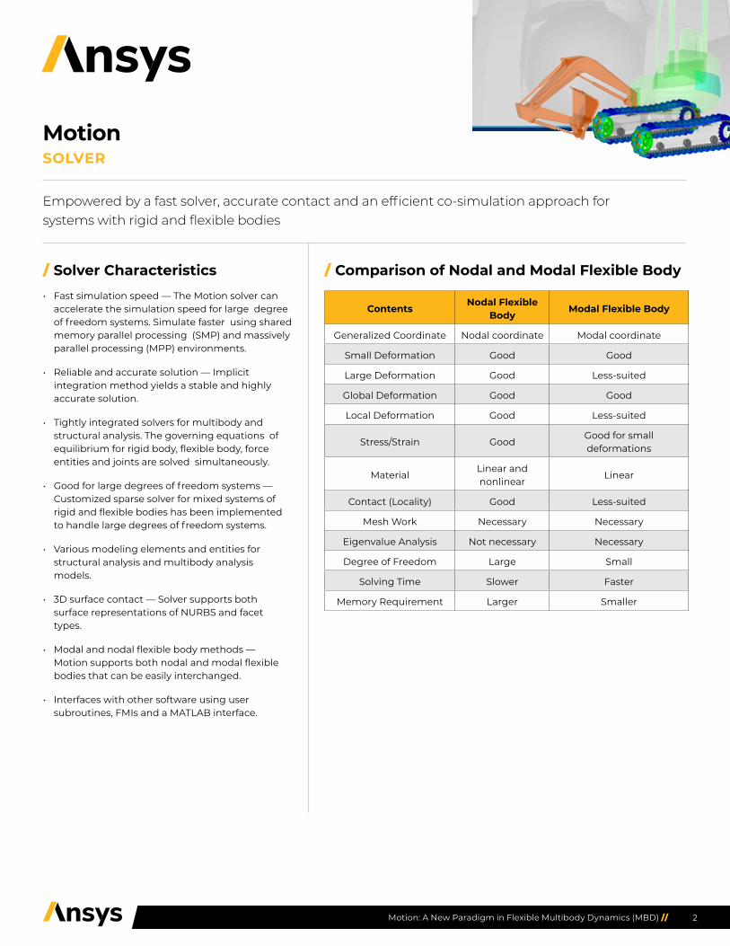
/ Comparison of Nodal and Modal Flexible Body
ContentsNodal Flexible
BodyModal Flexible Body
Generalized Coordinate Nodal coordinate Modal coordinate
Small Deformation Good Good
Large Deformation Good Less-suited
Global Deformation Good Good
Local Deformation Good Less-suited
Stress/Strain GoodGood for small deformations
MaterialLinear and nonlinear
Linear
Contact (Locality) Good Less-suited
Mesh Work Necessary Necessary
Eigenvalue Analysis Not necessary Necessary
Degree of Freedom Large Small
Solving Time Slower Faster
Memory Requirement Larger Smaller
Empowered by a fast solver, accurate contact and an efficient co-simulation approach for systems with rigid and flexible bodies
MotionSOLVER
3Motion: A New Paradigm in Flexible Multibody Dynamics (MBD) //
/ Analysis EnginesDynamics analysis is usually carried out to provides the solution to nonlinear dynamics problems where material nonlinearity, geometric nonlinear effects or changes in boundary conditions occur due to dynamic events, such as a contact and variable external loads. Inertia, damping, and spring and constrained forces are considered in the equation of motion. An implicit integration method is used. Kinematics analysis is automatically carried out when the degrees of freedom are zero.
Static analysis is usually carried out toprovides the solution to steady state with all nonlinear effects. Spring and constrained forces are considered in the equation of motion. One step or multiple load step methods in time domain are used. Quasi-static analyses are possible by using a multiple load step method.
Initial analysis calculates initial position, velocity and acceleration of a system. The position analysis determines the positions and orientations of bodies while minimizing the constraint violation in the equilibrium position. The velocity analysis determines the velocities of bodies with low or redundant initial velocities, while minimizing the constraint violations. The acceleration analysis determines the acceleration of bodies and forces while satisfying the constraint equation and equation of motion.
Eigenvalue analysis calculates the undamped natural frequency and mode of a system. The mass and stiffness of the system are considered, but the damping is not considered in this analysis type. Before the eigenvalues of the system are evaluated, the initial analysis is carried out and its solutions are used as an initial condition.
Body eigenvalue analysis calculates the undamped natural frequency and mode shape of a body such as nodal meshfree body and nodal FE body. The mass and stiffness of the body are considered while the damping is not.
Frequency response analysis calculates the response of a system in the frequency domain. This analysis is available in postprocessor after the eigenvalue analysis.
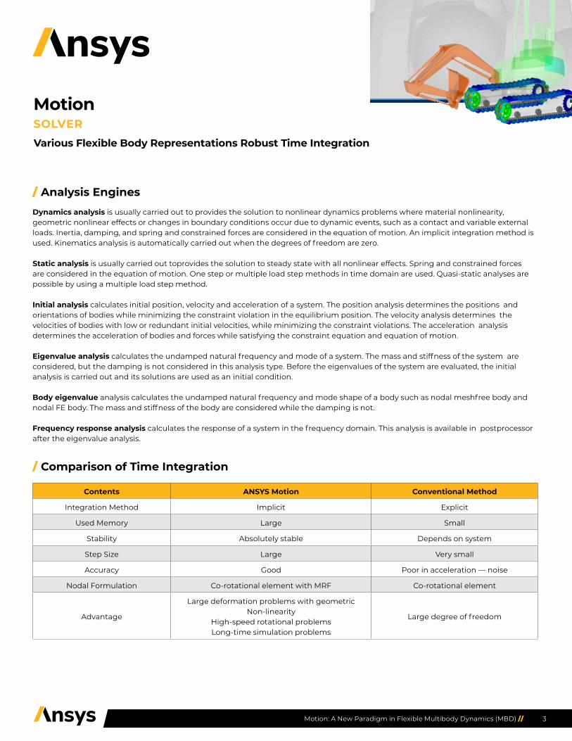
/ Comparison of Time Integration
Contents ANSYS Motion Conventional Method
Integration Method Implicit Explicit
Used Memory Large Small
Stability Absolutely stable Depends on system
Step Size Large Very small
Accuracy Good Poor in acceleration — noise
Nodal Formulation Co-rotational element with MRF Co-rotational element
Advantage
Large deformation problems with geometric Non-linearity
High-speed rotational problemsLong-time simulation problems
Large degree of freedom
Various Flexible Body Representations Robust Time Integration
MotionSOLVER

4Motion: A New Paradigm in Flexible Multibody Dynamics (MBD) //
/ Pre-processor Characteristics• ANSYS Motion pre-processor provides an optimized modeling environment for components and systems. Components can be
modeled as a single entity consisting of a part file and a mesh file. Part files and mesh files are treated and managed independently allowing for data reuse in other models.
• Necessary pickers are automatically activated to pick a point or direction. The pickers accelerate the creation and modification processes of various entities.
• CAD interface is available using STEP and Parasolid files. Direct import from CATIA V5 is possible. Many solid entities can be defined as one or many rigid bodies. Simple geometry models can be directly created inside ANSYS Motion.
• User friendly interface is available for rigid-rigid, rigid-flexible and flexible-flexible contact modeling, such as face picking and contact face specification and verification.
• Template subsystem can be used to create many model data from one template.
• Project management is supported by the embedded directory and file structure in ANSYS Motion.
• ANSYS Motion API using .NET Framework can be customized by programming C# and Visual Basic.
Contents ANSYS Motion
Geometry Modeling• Simple geometry and parameterization• Various CAD capability – STEP, CATIA, and Parasolid formats are supported
Constraints and Force Entities
• Joint, joint primitive, coupler constraints• Single, vector, matrix forces• Spring, bush, beam compliance forces• Function expression and user subroutine• Nonlinearity with spline
3D Contact Entities
• Alternative surface representation by triangular facets or NURBS• Rigid and flexible bodies contacts• Fast detecting method• Penetration method
Model Files
• Subsystem file is used to model a mechanical system• Mesh file is used to model a nodal or modal flexible body• Part file is used to model and assemble body • Template is used for a parametric model• Force file is used to model a special force for ANSYS Motion Car
Picker• Point picker, direction picker, orientation picker, transform picker• General picker, face picker, node picker• Faceset, nodeset, patchset picker
Open API• Programmable model building• New data can be added to standard GUI
MotionPRE-PROCESSOR

5Motion: A New Paradigm in Flexible Multibody Dynamics (MBD) //
/ Post-processor Characteristics• Post-processor provides fast animation of a system consisting of complicated geometries
• Contour plotting capabilities are included
• Fatigue analysis can be done in the post-processor without additional processing
• Distance and interference between two bodies can be checked in the post-processor
• Frequency response analysis can be done in the post-processor
• Various forms of stress and strain can be checked in contour form or time history plot
• New data can be added on the existing screen
• Deformed shape obtained from a simulation can be used as an initial condition of a flexible body
• Stress, strain and deformation of a cutting plane can be displayed
• Following camera is available to follow an object in a system
• Force vectors, including contact forces, are displayed in animation
• Deformation can be displayed with respect to a specified reference frame and is scalable
/ Main Features
Contents Entities
Animation
• Animation and plot synchronization• Contour display• Force and marker display• Displacement scaling• Cross section display• Following camera• Recording
Chart
• Multigraph• Arithmetic operation among curves• Data post-processing such as fast Fourier transform (FFT)• Plot configuration• Data export and import
MotionPOST-PROCESSOR

6Motion: A New Paradigm in Flexible Multibody Dynamics (MBD) //
/ Description• MBD pro performs kinematic and dynamic analyses of mechanical systems consisting of
rigid bodies. The rigid bodies are created by importing CAD data or simple geometries.
• The same hierarchy as the original CAD model can be maintained by using the subsystem concept. The joint or force entity can be modeled between a body and a subsystem or between two subsystems.
• A large degree of freedom system can be solved quickly by using the sparse solver.
• 3D contact problems can be solved smoothly by an optimized algorithm.
• Various joints and force entities are available.
• Functional expressions and user subroutines are available for user-defined algebraic equations and differential equations. Control systems and motor systems can be modeled by using the algebraic and differential equations. In-house codes can be linked using these functions.
• Position, velocity, acceleration and force outputs can be defined by functions or user subroutines.
Contents Entities
Analysis Dynamics, kinematics and static analysis
CAD ACIS, CATIA and STEP under each license
Parallel Process Shared memory parallel processing (SMP) and massively parallel processing (MPP) under each license
Body Rigid body with 6 DOF
Kinematic ConstraintFix, revolute, translational, screw, cylindrical, universal, planar, ball, orientation, distance, in-line, in-plane, parallel, perpendicular
Driving Constraint Displacement, velocity, acceleration motions in revolute, translational, cylindrical joints
Relative Constraint Coupler, gear, rack-and-pinion, cable
ForceTSD, RSD, bush, joint friction in revolute joint, T-Scalar, R-Scalar, vector, matrix, gravity, bearing force, tire, beam group
Contact Rigid-to-rigid 3D contact
Equation Variable, 1st order differential, 2nd order differential
Function Expression, user-subroutine
Sub-entity Spline, array
Included in ANSYS Motion base package. This module analyzes rigid body systems. The governing equations of motion are formulated based on a parametric generalized coordinate system. The rigid bodies are connected by joints, primitive constraints, bushings, contacts and user-defined function expressions. Smooth surface-to-surface contact is supported. The surface can be represented by piecewise triangular patches or a NURBS surface.
MotionMBD PRO

7Motion: A New Paradigm in Flexible Multibody Dynamics (MBD) //
/ Description• Mesh files in NASTRAN format can be used.
• Reliable and accurate solutions are obtained by using implicit integration.
• Large deformation problems and high-speed rotation problems can be solved easily.
• All multibody entities can be used to connect flexible bodies.
• 3D smooth contacts between rigid-flexible bodies and flexible-flexible bodies are available.
• Joint and force connections are available between rigid-flexible bodies and flexible-flexible bodies.
• Fatigue analysis can be performed in post-processor.
Contents Entities
Analysis Dynamics, kinematics and static analysis
CAD ACIS, CATIA and STEP under each license
Parallel Process SMP and MPP under each license
Body Rigid body with 6 DOF
Mesh File ANSYS Mechanical, NASTRAN
Material Isotropic, foam, hyperelastic, plasticity
Property Beam, shell, solid
Finite Element Beam2, shell3, shell6, shell4, solid10, solid6, solid8
Kinematic Constraint Fix, revolute, translational, screw, cylindrical, universal, planar, ball, orientation, distance, in-line, in-plane, parallel, perpendicular
Boundy Condition Fix, planar and general
Driving Constraint Displacement, velocity, acceleration motions in revolute, translational, cylindrical joints
Geometry Constraint Point-to-curve, curve-to-curve, point-to-surface, node-to-surface
Relative Constraint Coupler, gear, rack-and-pinion, cable
ForceTSD, RSD, bush, joint friction in revolute joint, T-Scalar, R-Scalar, vector, matrix, gravity, bearing force, tire, beam group
Contact Surface-to-surface in 3D, flex surface-to-surface in 3D, flex-surface-to-flex-surface in 3D
Equation Variable, 1st order differential, 2nd order differential
Function Expression, user subroutine
Sub-entity Spline, array
Included in ANSYS Motion base package. Dynamic analysis of a mixed system of rigid and flexible bodies can be performed. The solver was originally designed to contain the two different disciplines of MBD and finite element (FE) analysis. Therefore, there are many unique connecting elements of rigid and flexible bodies. Since the numerically stable implicit integration method is used, the solution is free from numerical noise and very smooth and reliable.
MotionFE DYNAMICS

8Motion: A New Paradigm in Flexible Multibody Dynamics (MBD) //
/ Description• A .dmap command file from ANSYS Motion can be used to
generate a NASTRAN .out file. A modal neutral file can be created from the .out file.
• Using a macro file, the .rst file can be easily accessed.
• A .dfmf file, a modal neutral file of ANSYS Motion, can be easily made and managed from a .out file.
• Modal information consists of nodal information and a .dfmf file. Because of the structure, the nodal information is contained within modal information so users can easily change to a nodal analysis method after a modal analysis to get a more detailed result.
• The modal flex method uses a .dfmesh file and it can build up models with constraints applied to the FE data in the same manner as a fully meshed FE analysis. Users need not learn about special modal flex modeling.
• Post-processing also shares user interface with nodal flex method.
Modify ANSYS Model ANSYS Analysis .rst File
ANSYS/Nastran Model Build
Eigenvalue Analysis
Build ANSYS Motion Mesh File
Check Modal Information
Build SystemAnalyse System and
View Results
ANSYS Motion Modal Flex Input File
Included in ANSYS Motion base package. When a flexible body has no contact or mildly changing force elements, the modal flexible body is preferred due to its efficiency. Mode shapes are extracted from a finite element program such as ANSYS Mechanical and deformation is expressed by the linear combination of the mode shapes. Since it solves reduced modal coordinates, the computation time is short. Modal flexible body and full nodal flexible body can be switched easily and can be solved with other rigid and nodal flexible bodies.
MotionMODAL FLEX
9Motion: A New Paradigm in Flexible Multibody Dynamics (MBD) //
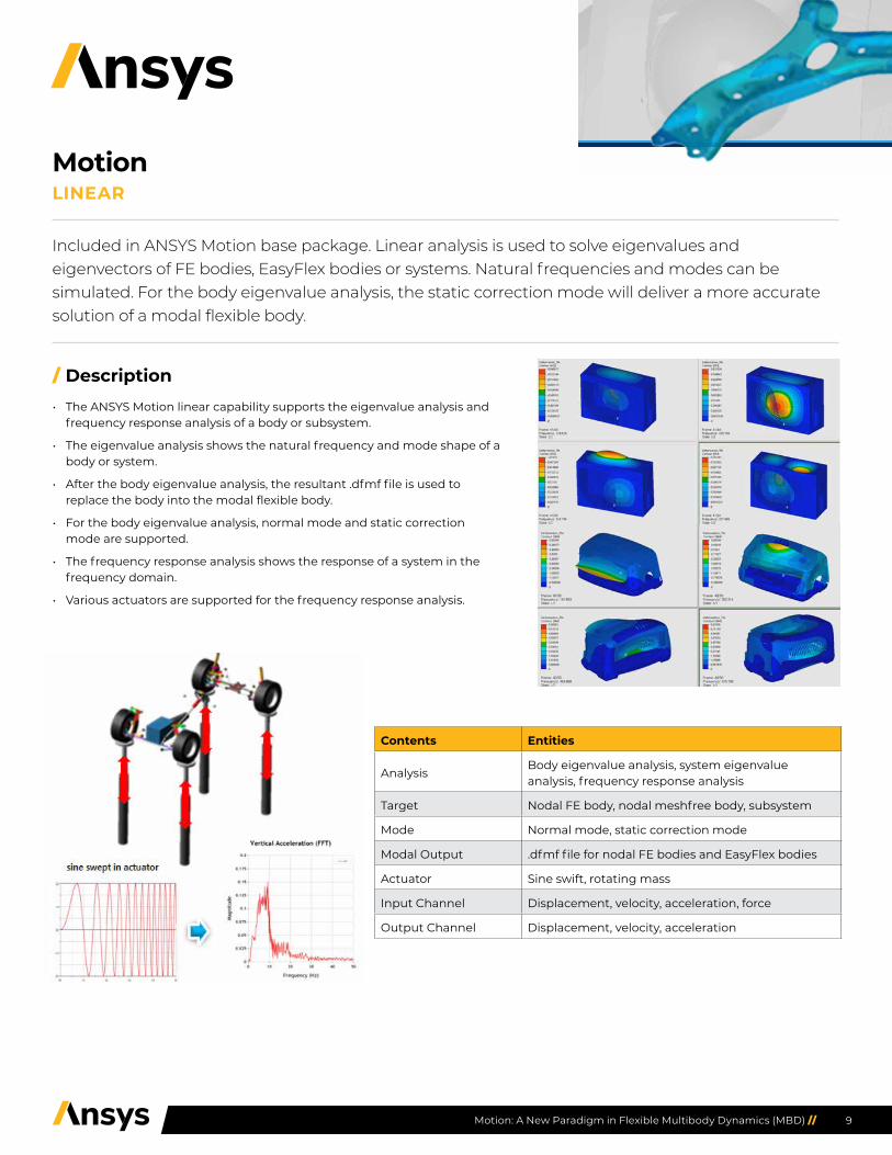
/ Description• The ANSYS Motion linear capability supports the eigenvalue analysis and
frequency response analysis of a body or subsystem.
• The eigenvalue analysis shows the natural frequency and mode shape of a body or system.
• After the body eigenvalue analysis, the resultant .dfmf file is used to replace the body into the modal flexible body.
• For the body eigenvalue analysis, normal mode and static correction mode are supported.
• The frequency response analysis shows the response of a system in the frequency domain.
• Various actuators are supported for the frequency response analysis.
Contents Entities
AnalysisBody eigenvalue analysis, system eigenvalue analysis, frequency response analysis
Target Nodal FE body, nodal meshfree body, subsystem
Mode Normal mode, static correction mode
Modal Output .dfmf file for nodal FE bodies and EasyFlex bodies
Actuator Sine swift, rotating mass
Input Channel Displacement, velocity, acceleration, force
Output Channel Displacement, velocity, acceleration
Included in ANSYS Motion base package. Linear analysis is used to solve eigenvalues and eigenvectors of FE bodies, EasyFlex bodies or systems. Natural frequencies and modes can be simulated. For the body eigenvalue analysis, the static correction mode will deliver a more accurate solution of a modal flexible body.
MotionLINEAR

10Motion: A New Paradigm in Flexible Multibody Dynamics (MBD) //
/ Description• Fatigue analysis in ANSYS Motion directly uses the result file from the
dynamic analysis in the post-processor. This tightly coupled process excludes extra data processing.
• Material and fatigue data are entered in post-processor; various fatigue analysis are then performed.
• Life cycle and damage are computed and checked by animation and graph.
• Minimal operation steps are necessary.
• Standard material library, including more than 200 material data, is supported.
• Function expression and user subroutines are available for user-defined algebraic equations and differential equations. Control system and motor system can be modeled by using the algebraic and differential equations. In-house code can be linked by these functions.
• Position, velocity, acceleration and force outputs can be defined in functions or user subroutines.
/ User Benefits• Time savings in modeling and analysis due to coupled approach.
• Synchronized solver results based in the time domain and animations.
• Convenient data availability with over 200 standard materials.
Contents Entities
S-NModified Goodman, Gerber, Sodeberg, De Georgi elliptic method
E-N Morrow, Smith-Watson-Topper (SWT) method
Material Standard material library, user material library
Included in ANSYS Motion base package. Conventional fatigue analysis has required two independent analyses of load history and stresses. These two processes are combined as one in the ANSYS Motion fatigue analysis system. The ANSYS Motion solver generates the load history and stress history at the same time. The fatigue life can be directly visualized in ANSYS Motion post-processor.
MotionFATIGUE
11Motion: A New Paradigm in Flexible Multibody Dynamics (MBD) //
/ Features• MATLAB input/output parameters can be easily defined by
using predefined functions.
• MATLAB input and output parameters and simulation conditions can be automatically coupled.
• ANSYS Motion process is defined as a MATLAB subroutine to minimize overhead in communication.
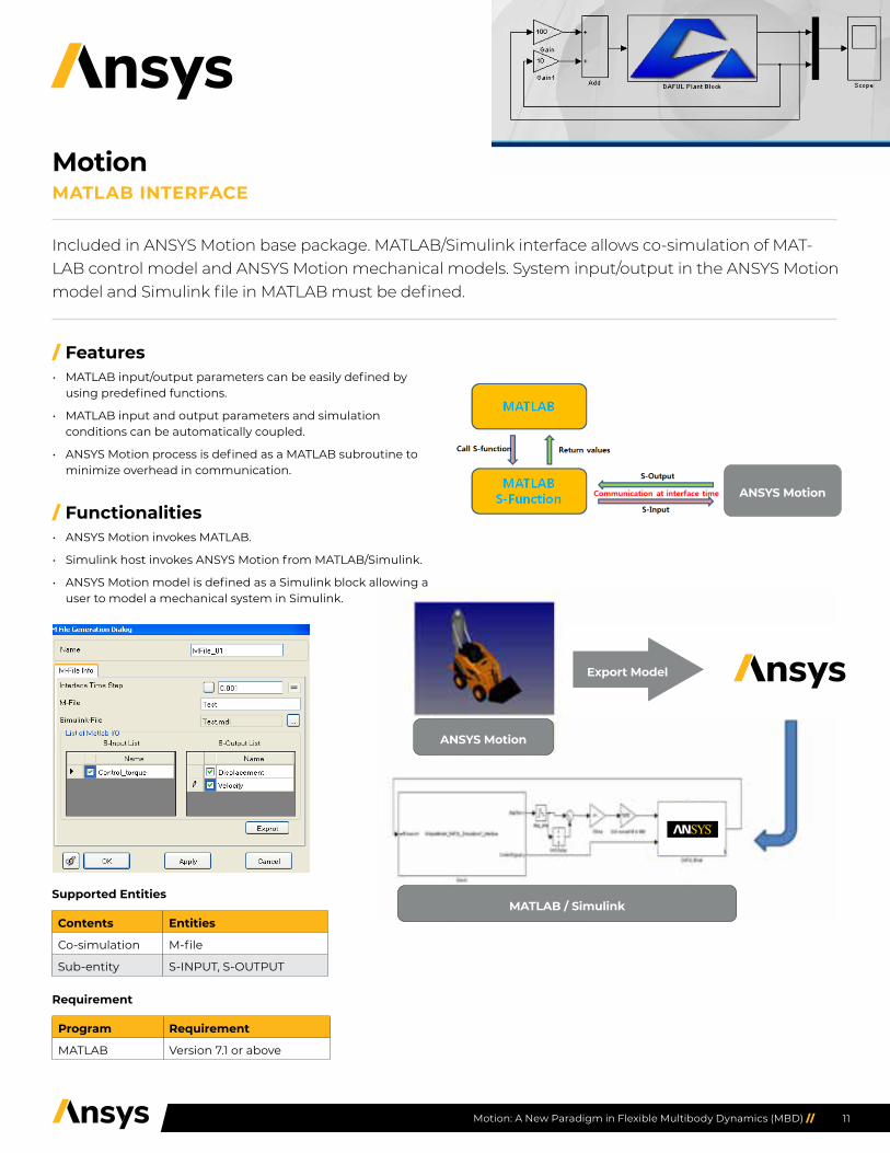
/ Functionalities• ANSYS Motion invokes MATLAB.
• Simulink host invokes ANSYS Motion from MATLAB/Simulink.
• ANSYS Motion model is defined as a Simulink block allowing a user to model a mechanical system in Simulink.
ANSYS Motion
MATLAB / Simulink
ANSYS Motion
Export Model
Supported Entities
Contents Entities
Co-simulation M-file
Sub-entity S-INPUT, S-OUTPUT
Requirement
Program Requirement
MATLAB Version 7.1 or above
Included in ANSYS Motion base package. MATLAB/Simulink interface allows co-simulation of MAT-LAB control model and ANSYS Motion mechanical models. System input/output in the ANSYS Motion model and Simulink file in MATLAB must be defined.
MotionMATLAB INTERFACE

12Motion: A New Paradigm in Flexible Multibody Dynamics (MBD) //
ANSYS Motion
ANSYS MotionMaster Simulator
Functional mockup interface for model exchange and tool coupling
/ Features• FMI input and output parameters can be easily defined
in ANSYS Motion by using predefined functions.
• FMI input and output parameters and simulation conditions are transferred in an FMU file.
• ANSYS Motion solver is defined as a communication library to minimize overheads in communication.
/ Functionalities• The master simulator invokes ANSYS Motion.
• The ANSYS Motion model is defined as an FMU block. This allows a user to model a mechanical system in the master simulator.
Supported Entities
Contents Entities
Co-simulation File generation
Sub-entity S-INPUT, S-OUTPUT
Requirement
Program Requirement
FMI Version 1.0
Engine Gearbox Thermal Systems Automated Cargo Door Chassis components, roadway
Included in ANSYS Motion base package. A functional mockup interface (FMI) capability facilitates co-simulation of an ANSYS Motion mechanical model with other simulation tools that support FMI. System input/output in the ANSYS Motion model must be defined. ANSYS Motion’s FMI is only available as a slave simulator.
MotionFMI
13Motion: A New Paradigm in Flexible Multibody Dynamics (MBD) //
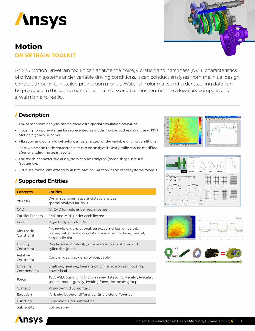
/ Description• The component analysis can be done with special simulation scenarios.
• Housing components can be represented as modal flexible bodies using the ANSYS Motion eigenvalue solver.
• Vibration and dynamic behavior can be analyzed under variable driving conditions.
• Gear whine and rattle characteristics can be analyzed. Gear profile can be modified after analyzing the gear results.
• The mode characteristic of a system can be analyzed (mode shape, natural frequency).
• Driveline model can extend to ANSYS Motion Car toolkit and other systems models.
/ Supported Entities
Contents Entities
AnalysisDynamics, kinematics and static analysis, special analysis for NVH
CAD All CAD formats under each license
Parallel Process SMP and MPP under each license
Body Rigid body with 6 DOF
Kinematic Constraint
Fix, revolute, translational, screw, cylindrical, universal, planar, ball, orientation, distance, in-line, in-plane, parallel, perpendicular
Driving Constraint
Displacement, velocity, acceleration, translational and cylindrical joints
Relative Constraint
Coupler, gear, rack-and-pinion, cable
Driveline Components
Shaft set, gear set, bearing, clutch, synchronizer, housing, power load
ForceTSD, RSD, bush, joint friction in revolute joint, T-scalar, R-scalar, vector, matrix, gravity, bearing force, tire, beam group
Contact Rigid-to-rigid 3D contact
Equation Variable, 1st order differential, 2nd order differential
Function Expression, user subroutine
Sub-entity Spline, array
ANSYS Motion Drivetrain toolkit can analyze the noise, vibration and harshness (NVH) characteristics of drivetrain systems under variable driving conditions. It can conduct analyses from the initial design concept through to detailed production models. Waterfall color maps and order tracking data can be produced in the same manner as in a real-world test environment to allow easy comparison of simulation and reality.
MotionDRIVETRAIN TOOLKIT
14Motion: A New Paradigm in Flexible Multibody Dynamics (MBD) //
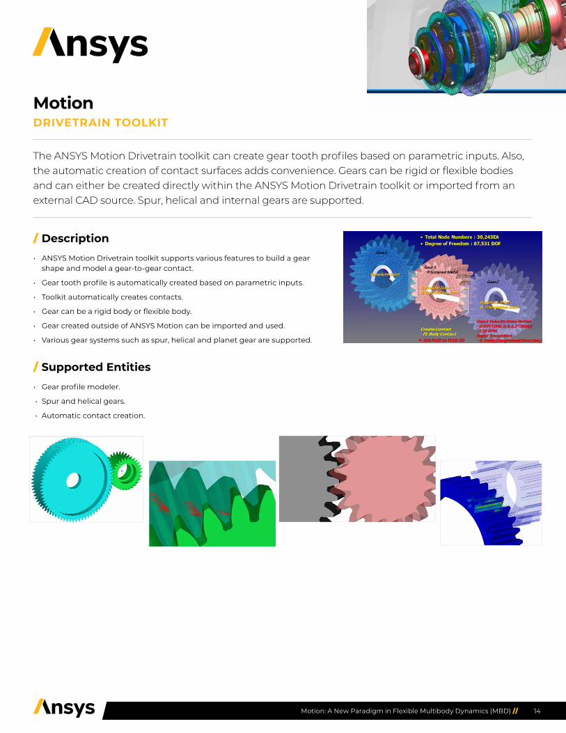
/ Description• ANSYS Motion Drivetrain toolkit supports various features to build a gear
shape and model a gear-to-gear contact.
• Gear tooth profile is automatically created based on parametric inputs.
• Toolkit automatically creates contacts.
• Gear can be a rigid body or flexible body.
• Gear created outside of ANSYS Motion can be imported and used.
• Various gear systems such as spur, helical and planet gear are supported.
/ Supported Entities• Gear profile modeler.
• Spur and helical gears.
• Automatic contact creation.
The ANSYS Motion Drivetrain toolkit can create gear tooth profiles based on parametric inputs. Also, the automatic creation of contact surfaces adds convenience. Gears can be rigid or flexible bodies and can either be created directly within the ANSYS Motion Drivetrain toolkit or imported from an external CAD source. Spur, helical and internal gears are supported.
MotionDRIVETRAIN TOOLKIT

15Motion: A New Paradigm in Flexible Multibody Dynamics (MBD) //
/ Description• ANSYS Motion Links models consist of path bodies (wound bodies) and
segment bodies (winding bodies).
• Once the path and segment bodies are defined, chain assembly is automatically created.
• Path and segment bodies can be a subsystem, part or mesh files. This allows users to build various types of irregular chains.
• One window controls all contact parameters along the segment and path bodies.
• Connections between two segments can be any kind of force, joint or contact entity.
• Irregular appearance of several segment types is supported with an appearance table.
• Engagement of a chain segment and sprocket tooth can be matched automatically.
/ Functionalities• Segment and path bodies can be flexible or rigid.
• Segment and path subsystems or bodies can be simply managed by ANSYS Motion.
/ Supported Entities
Contents Entities
Analysis Dynamics, kinematics and static analysis
Assembly Subsystem
Body FE body and assembled body
Chained system Chained system
An ANSYS Motion Links toolkit analysis consists of path bodies (wound bodies) and segment bodies (winding bodies). Once the path and segment bodies are defined, a chain assembly is automatically created. Path and segment bodies can be a subsystem, part or mesh files. This allows a user to build various types of irregular chains. One window controls all the contact parameters among the segment and path bodies. Connections between two segments can be any kind of force, joint or contact entity.
MotionLINKS TOOLKIT FOR CHAINS AD BELTS

16Motion: A New Paradigm in Flexible Multibody Dynamics (MBD) //
/ Description• Predefined geometries for segments and path bodies are provided so that a
parametric study is possible for these bodies.
• Chain assembly is simplified to eliminate the picking step of path bodies. The path bodies are automatically searched and used to automatically assemble the track segments.
• Contact surfaces are automatically defined for the predefined geometries.
• The predefined geometries can include complicated modeling details to represent real shapes.
• Tracks and chains are automatically assembled with path and segments.
Predefined geometries for segment and path bodies are provided so that a parametric study is possi-ble. Track assembly is further simplified to eliminate the picking step of path bodies. The path bodies are automatically searched and used to automatically assemble the track segments. Contact surfaces are automatically defined for the predefined geometries so that contact surfaces do not need to be defined. The predefined geometries have complicated modeling details to represent the real shapes.
MotionLINKS TOOLKIT FOR TRACKS

17Motion: A New Paradigm in Flexible Multibody Dynamics (MBD) //
/ Description• ANSYS Motion Car supports various features to simulate K&C and R&H
analysis for automotive.
• Dedicated template and subsystem modeling tools can be used to build chassis, suspension, steering and wheels for predefined analysis scenarios.
• The toolkit has symmetric modeling capability.
• Template-based modeling easily manages vehicle models.
• A half car model can be analyzed independently and can be automatically assembled for a full car.
• Subsystems can be connected when they are assembled together.
• Suspension analysis scenarios and output items are predefined so that a user can easily check the design requirements.
/ Supported Entities
Contents Entities
AnalysisDynamics, kinematics and static analysis, special analysis for ANSYS Motion Car
CAD All CAD ACIS, CATIA and STEP under each license
Parallel Process SMP and MPP under each license
Body Rigid body with 6 DOF
Kinematic Constraint
Fix, revolute, translational, screw, cylindrical, universal, planar, ball, orientation, distance, in-line, in-plane, parallel, perpendicular
Driving Constraint
Displacement, velocity, acceleration, translational and cylindrical joints
Relative Constraint
Coupler, gear, rack-and-pinion, cable
Driveline Components
Shaft set, gear set, bearing, clutch, synchronizer, housing, power load
ForceTSD, RSD, bush, joint friction in revolute joint, T-scalar, R-scalar, vector, matrix, gravity, bearing force, tire, beam group
Contact Rigid-to-rigid 3D contact
Equation Variable, 1st order differential, 2nd order differential
Function Expression, user subroutine
Sub-entity Spline, array
Dedicated template and subsystem modeling tools can be used to build chassis, suspension, steering and wheels for predefined analysis scenarios. Symmetric modeling capabilities and template-based workflows allow users to easily analyze kinematics and compliance (K&C) and ride and handling (R&H) scenarios.
MotionCAR TOOLKIT

18Motion: A New Paradigm in Flexible Multibody Dynamics (MBD) //
/ Description• ANSYS Motion EasyFlex does not generate a mesh so users who lack meshing skills may conduct flexibility analyses.
• The toolkit supports various 3D CAD types and modeling based on CAD geometry.
• Rigid body, tie and spot weld elements can be modeled between two EasyFlex bodies.
• Using a local refinement, ANSYS Motion EasyFlex can obtain good results even with a small degree of freedom.
• It reduces the time and cost associated with the simplification of the design process and allows for automation between the design process and CAE.
• It can account for contact nonlinearities.
/ Supported Entities
Contents Entities
Analysis Dynamics, kinematics and static analysis,
CAD All CAD ACIS, CATIA and STEP under each license
Parallel Process SMP and MPP under each license
Body Meshfree body
Meshfree Entity Rigid body elements (RBEs), tie, spot weld
Kinematic Constraint
Fix, revolute, translational, screw, cylindrical, universal, planar, ball, orientation, distance, in-line, in-plane, paral-lel, perpendicular
Driving Constraint
Displacement, velocity, acceleration, translational and cylindrical joints
Relative Constraint
Coupler, gear, rack-and-pinion, cable
ForceTSD, RSD, bush, joint friction in revolute joint, T-scalar, R-scalar, vector, matrix, gravity, bearing force, tire, beam group
Contact General contact
Equation Variable, 1st order differential, 2nd order differential
Function Expression, user subroutine
Sub-entity Spline, array
Design Change
Local Refinement (Power)
Unlike conventional finite element analysis, the ANSYS Motion EasyFlex toolkit does not require meshing prior to structural analysis. Since the meshing of complex 3D CAD is not needed, it makes flexibility modeling available to all users, even those unfamiliar with meshing technologies. By using the ANSYS Motion EasyFlex toolkit, the strain and stress of machine parts with various shapes can be calculated within minutes.
MotionEASYFLEX TOOLKIT

19Motion: A New Paradigm in Flexible Multibody Dynamics (MBD) //
/ Description• The geometries in the ANSYS Motion pre-processor are represented with the ACIS kernel. As a result, when other CAD types are
imported to ANSYS Motion, they must be translated to the ACIS kernel. ANSYS Motion supports several CAD translators with each corresponding license.
• Translators allow for the automatic creation of bodies from a CAD file.
• Many solid geometries can be defined as one body.
• Units are automatically defined.
/ Supported Entities
Contents Entities Necessary Package
ACIS .sat, .sab –
CATIA .catpart, .catproduct ANSYS Motion CATIA Translator
Parasolid .x_t, .x_b ANSYS Motion Parasolid Translator
STEP .stp, .step ANSYS Motion STEP Translator
ANSYS Motion pre-processor is developed on the ACIS kernel; .sat, .sab files can be read directly. Other CAD data files must be translated through the corresponding CAD translator.
MotionCAD TRANSLATORS