Foreword Introduction 1 Scope 2 Normative reference 3 Terms and definitions

AANNSSII//CCTTAA SSttaannddaarrdd PPeerrssoonnaall SSoouunndd AAmmpplliiffiiccaattiioonn PPeerrffoorrmmaannccee CCrriitteerriiaa AANNSSII//CCTTAA--22005511 JJaannuuaarryy 22001177

NOTICE
Consumer Technology Association (CTA)™ Standards, Bulletins and other technical publications are designed to serve the public interest through eliminating misunderstandings between manufacturers and purchasers, facilitating interchangeability and improvement of products, and assisting the purchaser in selecting and obtaining with minimum delay the proper product for his particular need. Existence of such Standards, Bulletins and other technical publications shall not in any respect preclude any member or nonmember of the Consumer Technology Association from manufacturing or selling products not conforming to such Standards, Bulletins or other technical publications, nor shall the existence of such Standards, Bulletins and other technical publications preclude their voluntary use by those other than Consumer Technology Association members, whether the standard is to be used either domestically or internationally. Standards, Bulletins and other technical publications are adopted by the Consumer Technology Association in accordance with the American National Standards Institute (ANSI) patent policy. By such action, the Consumer Technology Association does not assume any liability to any patent owner, nor does it assume any obligation whatever to parties adopting the Standard, Bulletin or other technical publication. This document does not purport to address all safety problems associated with its use or all applicable regulatory requirements. It is the responsibility of the user of this document to establish appropriate safety and health practices and to determine the applicability of regulatory limitations before its use. This document is copyrighted by the Consumer Technology Association (CTA)™ and may not be reproduced, in whole or part, without written permission. Federal copyright law prohibits unauthorized reproduction of this document by any means. Organizations may obtain permission to reproduce a limited number of copies by entering into a license agreement. Requests to reproduce text, data, charts, figures or other material should be made to the Consumer Technology Association (CTA)™.
(Formulated under the cognizance of the CTA R6 Portable, Handheld and In-Vehicle Electronics Committee.)
Published by CONSUMER TECHNOLOGY ASSOCIATION 2017 Technology & Standards Department www.cta.tech All rights reserved

CTA-2051
FOREWORD
This standard was developed by the Consumer Technology Association’s R6 Portable Handheld and In-Vehicle Electronics Committee.
i

CTA-2051
(This page intentionally left blank.)
ii
CTA-2051
CONTENTS
1 Scope......................................................................................................................................................... 1
2 Normative References ............................................................................................................................. 1 2.1.1 Normative Reference List .......................................................................................................... 1 2.1.2 Normative Reference Acquisition ............................................................................................. 1
2.2 Informative References .................................................................................................................... 1 2.2.1 Informative Reference List ......................................................................................................... 1 2.2.2 Informative Reference Acquisition ........................................................................................... 2
2.3 Compliance Notation ........................................................................................................................ 3
3 Definitions ................................................................................................................................................. 3 3.1 Symbols and Abbreviations ............................................................................................................ 5
4 Criteria for Standardization ..................................................................................................................... 5 4.1 Frequency Response Bandwidth (Category 1) .............................................................................. 6 4.2 Frequency Response Smoothness (Category 1) ........................................................................ 10 4.3 Maximum Acoustic Output (Category 1) ...................................................................................... 10 4.4 Distortion Control Limits (Category 1) ......................................................................................... 10
4.4.1 Output Distortion ...................................................................................................................... 10 4.4.2 Input Distortion ......................................................................................................................... 10
4.5 Self-generated Noise Levels (Category 1) ................................................................................... 11 4.6 High Frequency Gain Provided (Category 2) ............................................................................... 11 4.7 Battery Life (Category 2) ................................................................................................................ 11 4.8 Latency (Category 2) ...................................................................................................................... 12 4.9 RF-Immunity (Category 2) .............................................................................................................. 12 4.10 Fixed or Level Dependent Frequency Equalization - Tone Control (Category 3) .................. 12 4.11 Level Dependent Gain/Compression (Category 3) .................................................................... 12 4.12 SNR Enhancement (Category 3) ................................................................................................. 12 4.13 Noise Reduction (Category 3) ..................................................................................................... 12 4.14 Feedback Control / Cancellation (Category 3) ........................................................................... 12 4.15 Personalization (Category 3) ....................................................................................................... 13
4.15.1 General ..................................................................................................................................... 13 4.15.2 Specification and Reporting .................................................................................................. 13
4.16 Device Coupling to the Ear (Category 3) .................................................................................... 13 4.17 Wireless Connectivity (Category 3) ............................................................................................ 13
Annex A: Maximum Acoustic Output ...................................................................................................... 14
iii

CTA-2051
(This page intentionally left blank.)
iv
CTA-2051
Personal Sound Amplification Performance Criteria
1 Scope This standard includes technical performance metrics and associated target values for consumer products that provide personal sound amplification and/or enhancement to a user. Products shall meet the stated requirements to be considered as compliant to this standard. Personal sound amplification may be a single function within a larger set of device capabilities. Descriptions of feature specific device performance baselines and metrics of measurement are described. Device performance capabilities have been divided into feature specific sub-sections that identify: required minimum performance values, metrics of measurement necessary to identify feature specific performance values, and methods of reporting prescribed to each feature specific value.
2 Normative References The following standards contain provisions that, through reference in this text, constitute normative provisions of this standard. At the time of publication, the editions indicated were valid. All standards are subject to revision, and parties to agreements based on this standard are encouraged to investigate the possibility of applying the most recent editions of the standards listed here.
2.1.1 Normative Reference List
1. ANSI S3.22-2009, Specification of hearing aid characteristics 2. IEC-60118-0-2015, Electroacoustics – Hearing aids – Part 0: Measurement of the performance
characteristics of hearing aids 3. IEC-60118-7-2005, Electroacoustics – Hearing aids – Part 7: Measurement of the performance
characteristics of hearing aids for quality inspection for delivery
2.1.2 Normative Reference Acquisition
1. Acoustical Society of America, 1305 Walt Whitman Road, Suite 300 Melville, NY 11747, 516-576-2360, https://global.ihs.com/home_page_asa.cfm?&rid=ASA
2. International Electrotechnical Commission, 3, rue de Varembé P.O. Box 131 CH - 1211 Geneva 20 – Switzerland, +41 22 919 02 11, http://www.iec.ch/
3. International Electrotechnical Commission, 3, rue de Varembé P.O. Box 131 CH - 1211 Geneva 20 – Switzerland, +41 22 919 02 11, http://www.iec.ch/
2.2 Informative References The following references contain provisions that, through reference in this text, constitute informative provisions of this standard. At the time of publication, the edition indicated was valid. All standards are subject to revision, and parties to agreements based on this standard are encouraged to investigate the possibility of applying the most recent edition of the standard indicated below.
2.2.1 Informative Reference List 1. ANSI/S1.1-2013, Acoustical terminology 2. ANSI/S3.2-2009, Method for measuring the intelligibility of speech over communication systems 3. ANSI/S3.25-2009, Occluded Ear Simulator 4. ANSI/S3.30-1995(R2008), Bioacoustical terminology 5. ANSI/S3.35-2010, Method of measurement of performance characteristics of hearing aids under
simulated real-ear working conditions 6. ANSI/S3.42-Part1-1992(R2012), Part 1: Testing hearing aids with broad-band noise signal
1
CTA-2051
7. ANSI/S3.42-Part2-2012, Part 2: Method of characterizing signal processing in hearing aids with speech-like signal
8. ANSI/S3.46-2013, Method of measurement of real-ear performance characteristics of hearing aids
9. ANSI/S3.47-2014, Specification of performance measurements of hearing assistive devices and systems
10. ANSI/C63.19-2011, Compatibility between hearing aids and cellular telephones 11. IEC-60065-2002 + A12:2011, Audio video and similar electronic apparatus: safety 12. IEC-50332-1-2013, Sound system equipment: Headphones and earphones associated with
personal music players – maximum SPL measurement method – Part 1: General method for “one package equipment”
13. IEC-60118-8-2005, Electroacoustics – Hearing aids – Part 8: Methods of measurement of performance characteristics of hearing aids under simulated in-situ working conditions
14. IEC-60118-13, Electroacoustics – Hearing aids – Part 13: Electromagnetic compatibility (EMC) 15. IEC-60118-14-1998, Electroacoustics – Hearing aids – Part 14: Specification of a digital interface
device 16. IEC-60118-15-2012, Electroacoustics – Hearing aids – Part 15: Methods for characterizing signal
processing in hearing aids with a speech-like signal 17. IEC-60318-4-2010, Electroacoustics – Simulators of human head and ear –Part 4: Occluded-ear
simulator for the measurement of earphones coupled to the ear by means of ear inserts 18. IEC-60601-2-66, Medical electrical equipment - Part 2-66: Particular requirements for the basic
safety and essential performance of hearing instruments and hearing instrument systems 19. IEC-61669-2001, Electroacoustics - Equipment for the measurement of real-ear acoustical
characteristics of hearing aids 20. ISO-12124-2001, Acoustics – Procedures for the measurement of real-ear acoustical
characteristics of hearing aids 21. ISO-11904-1-2002, Acoustics – Determination of sound emission from sound sources placed
close to the ear - Part 1: Technique using a microphone in the real ear (MIRE technique) 22. ISO-11904-2-2004, Acoustics - Determination of sound emission from sound sources placed
close to the ear - Part 2: Technique using a manikin 23. Killion MC and Monser EL (1980) “CORFIG: Coupler response for flat insertion gain,” Chapter 8
in Acoustical Factors Affecting Hearing Aid Performance, Studebaker GA and Hochberg I, eds. (University Park Press, Baltimore).
24. Killion MC and Revit LJ (1993) “CORFIG and GIFROC: Real Ear to Coupler and Back,” Chapter 5 in Acoustical Factors Affecting Hearing Aid Performance (2nd ed.), Studebaker GA and Hochberg I, eds. (Allyn and Bacon, Toronto), p. 65-86.
25. Killion MC, Berger EH and Nuss RA (1987) Diffuse field response of the ear. J. Acoust. Soc. Am. Suppl.1 vol 81, S75
26. IEEE-269-2010, IEEE Standard Methods for Measuring Transmission Performance of Analog and Digital Telephone Sets, Handsets, and Headsets
2.2.2 Informative Reference Acquisition
1. Acoustical Society of America, 1305 Walt Whitman Road, Suite 300 Melville, NY 11747, 516-576-2360, https://global.ihs.com/home_page_asa.cfm?&rid=ASA
2. Acoustical Society of America, 1305 Walt Whitman Road, Suite 300 Melville, NY 11747, 516-576-2360, https://global.ihs.com/home_page_asa.cfm?&rid=ASA
3. Acoustical Society of America, 1305 Walt Whitman Road, Suite 300 Melville, NY 11747, 516-576-2360, https://global.ihs.com/home_page_asa.cfm?&rid=ASA
4. Acoustical Society of America, 1305 Walt Whitman Road, Suite 300 Melville, NY 11747, 516-576-2360, https://global.ihs.com/home_page_asa.cfm?&rid=ASA
5. Acoustical Society of America, 1305 Walt Whitman Road, Suite 300 Melville, NY 11747, 516-576-2360, https://global.ihs.com/home_page_asa.cfm?&rid=ASA
6. Acoustical Society of America, 1305 Walt Whitman Road, Suite 300 Melville, NY 11747, 516-576-2360, https://global.ihs.com/home_page_asa.cfm?&rid=ASA
2
CTA-2051
7. Acoustical Society of America, 1305 Walt Whitman Road, Suite 300 Melville, NY 11747, 516-576-2360, https://global.ihs.com/home_page_asa.cfm?&rid=ASA
8. Acoustical Society of America, 1305 Walt Whitman Road, Suite 300 Melville, NY 11747, 516-576-2360, https://global.ihs.com/home_page_asa.cfm?&rid=ASA
9. Acoustical Society of America, 1305 Walt Whitman Road, Suite 300 Melville, NY 11747, 516-576-2360, https://global.ihs.com/home_page_asa.cfm?&rid=ASA
10. IEEE, 445 Hoes Lane Piscataway, NJ 08854, 732-981-0060 http://standards.ieee.org/index.html 11. International Electrotechnical Commission, 3, rue de Varembé P.O. Box 131 CH - 1211 Geneva
20 – Switzerland, +41 22 919 02 11, http://www.iec.ch/ 12. International Electrotechnical Commission, 3, rue de Varembé P.O. Box 131 CH - 1211 Geneva
20 – Switzerland, +41 22 919 02 11, http://www.iec.ch/ 13. International Electrotechnical Commission, 3, rue de Varembé P.O. Box 131 CH - 1211 Geneva
20 – Switzerland, +41 22 919 02 11, http://www.iec.ch/ 14. International Electrotechnical Commission, 3, rue de Varembé P.O. Box 131 CH - 1211 Geneva
20 – Switzerland, +41 22 919 02 11, http://www.iec.ch/ 15. International Electrotechnical Commission, 3, rue de Varembé P.O. Box 131 CH - 1211 Geneva
20 – Switzerland, +41 22 919 02 11, http://www.iec.ch/ 16. International Electrotechnical Commission, 3, rue de Varembé P.O. Box 131 CH - 1211 Geneva
20 – Switzerland, +41 22 919 02 11, http://www.iec.ch/ 17. International Electrotechnical Commission, 3, rue de Varembé P.O. Box 131 CH - 1211 Geneva
20 – Switzerland, +41 22 919 02 11, http://www.iec.ch/ 18. International Electrotechnical Commission, 3, rue de Varembé P.O. Box 131 CH - 1211 Geneva
20 – Switzerland, +41 22 919 02 11, http://www.iec.ch/ 19. International Electrotechnical Commission, 3, rue de Varembé P.O. Box 131 CH - 1211 Geneva
20 – Switzerland, +41 22 919 02 11, http://www.iec.ch/ 20. International Organization for Standardization, Chemin de Blandonnet 8 CP 401 1214 Vernier,
Geneva Switzerland, +41 22 749 01 11, http://www.iso.org/iso/home.html 21. International Organization for Standardization, Chemin de Blandonnet 8 CP 401 1214 Vernier,
Geneva Switzerland, +41 22 749 01 11, http://www.iso.org/iso/home.html 22. International Organization for Standardization, Chemin de Blandonnet 8 CP 401 1214 Vernier,
Geneva Switzerland, +41 22 749 01 11, http://www.iso.org/iso/home.html 23. International Organization for Standardization, Chemin de Blandonnet 8 CP 401 1214 Vernier,
Geneva Switzerland, +41 22 749 01 11, http://www.iso.org/iso/home.html 24. http://www.etymotic.com/media/publications/erl-0091-1993.pdf 25. Acoustical Society of America, 1305 Walt Whitman Road, Suite 300 Melville, NY 11747, 516-576-
2360, https://global.ihs.com/home_page_asa.cfm?&rid=ASA 26. IEEE, 501 Hoes Lane, Piscataway, NJ, 08854, 732-981-0060 http://www.ieee.org
2.3 Compliance Notation As used in this document “shall” and “must” denote mandatory provisions of the standard. “Should” denotes a provision that is recommended but not mandatory. “May” denotes a feature whose presence does not preclude compliance, and implementation of which is optional. “Optional” denotes items that may or may not be present in a compliant device. 3 Definitions
Acoustical Coupler An acoustical Coupler is a cavity of specified shape and volume used for the calibration of earphones or microphones in conjunction with a calibrated microphone adapted to measure the sound pressure developed in the cavity.
NOTE Acoustical couplers are specified in ANSI/ASA S3.55-2014/Part 1/IEC 60318-1:2009, ANSI/ASA S3.55-2015/Part 3/IEC 60318-3:2014, and ANSI/ASA S3.55-2014/Part 5/IEC 60318-5:2006.
3

CTA-2051
Automatic Gain Control Automatic Gain Control is a means (other than peak clipping) by which the gain is automatically controlled as a function of the level of the signal being amplified.
CORFIG CORFIG denotes Coupler Response for Flat Insertion Gain. The CORFIG tables (Table 4.1A, B and C) are corrections used with laboratory measurements of hearing devices to enable estimation of the expected "real ear" response a wearer will receive.
Compression Compression is a means by which the amount of amplification (gain) decreases automatically as the signal level increases.
dBA dBA refers to sound pressure level that is filtered by an A-weighting filter prior to computing the overall level. The A weighting approximately accounts for the frequency dependence of relative loudness perceived by the human ear.
Insertion Gain Insertion Gain is the difference (in dB) between the sound pressure level measured with the device in situ and that obtained in the open ear.
NOTE: Insertion gain may be measured with a probe microphone on a human listener or using a manikin equipped with an ear simulator.
Insertion Response Insertion Response is the Insertion Gain versus frequency. Linear Amplification A change in input results in the same relative change in output;
in particular there is no change in gain with change in input level. Limiting Signal processing to keep the output level from exceeding a
threshold (i.e., limit), typically achieved by quickly reducing the gain applied to high-level input signals.
Manikin (head and torso simulator) A head and torso simulator extending downward from the top of the head to the waist and designed to simulate the sound pick-up characteristics and acoustic diffraction produced by a median adult human head and torso.
Multiband Equalization Frequency shaping achieved by separate adjustment of the gain
in more than one band. The resulting frequency response may be independent of level (simple equalization) or may change with level (level dependent frequency response). The latter is typically used for those desiring increased gain for soft high frequency sounds but do not wish loud low frequency sounds to be amplified.
Multiband Signal Processing The frequency bandwidth of the device is divided into more than
one band, enabling individual control of the processing in each band. Example use cases are compression, equalization, noise rejection, and feedback rejection.
4
CTA-2051
Occluded Ear Simulator A device used for testing which approximates the acoustic transfer impedance of the inner part of the human ear canal, from the tip acoustic output of an ear mold insert device to the eardrum. In the case of hearing devices that do not insert into the ear canal, e.g. earphones that are designed to lay in the concha or be laced over the ear, a Head and Torso Simulator, as defined in ANSI S3.36 is appropriate for testing.
Real Ear Coupler Difference Denotes the difference between (a) the response of an in-situ
device measured at the eardrum and (b) the same device measured in a coupler. Average values of these differences are shown in Table 4.1C.
Single Band Signal Processing Signal processing (e.g., compression) applied by treating the
entire frequency bandwidth of the device as a single channel. THD+N Denotes Total Harmonic Distortion plus Noise. It represents (a)
the sum of the powers of all harmonic distortion components plus noise divided by (b) the power of the fundamental (test) signal frequency. The square root of this ratio is expressed in percent.
Wide Dynamic Range Compression Non-linear processing that is differentially applied to sounds as a
function of their level. It is typically done so as to amplify soft sounds more so than loud sounds, thereby reducing the dynamic range.
NOTE: Wide Dynamic Range Compression and Limiting are similar in process but different in degree and perceived effect.
3.1 Symbols and Abbreviations AGC Automatic Gain Control CORFIG Coupler Response for Flat Insertion Gain dB Decibel dBA A-weighted Decibels OSPL Output Sound Pressure Level RECD Real Ear Coupler Difference SNR Signal to Noise Ratio SPL Sound Pressure Level THD Total Harmonic Distortion
4 Criteria for Standardization Three categories of standardization level are defined and described below. These categories identify three levels of technical performance specification differentiated by a decrease in the degree of standardized specification required for fulfilment of the feature requirements. The level of performance specification recommended by this document for each feature is independently identified for each feature within the associated sub-section. Measurement methods for evaluation of all relevant metrics characterized in the feature specific sub-sections are identified and described when appropriate. Category 1: The description of a hearing device performance parameter which must include the value measured per the specified testing method. Category 1 requirements include a threshold or acceptable
5
CTA-2051
range for the parameter measured. Category 2: The description of a hearing device performance parameter which must include the value measured per the specified testing method. Category 2 requirements do not include a threshold or acceptable range for the parameter measured. Category 3: Presence of the technological capability or feature shall be reported in the device description. The specific value/metric for measurement of this value is not within the scope of the standard. Measurements in this standard specify the use of tones (sine waves) as a stimulus signal. It is recognized that many devices will include non-linear audio processing (DSP) (for example, noise suppression, band equalization) that may cause unexpected test results when tones are used as test stimulus signals. Therefore, when performing measurements using tones as specified in Section 4.1, 4.2, 4.3, 4.4, 4.5, 4.6, and 4.7, any non-linear signal processing should be disabled. Alternatively, if using tones is not appropriate for testing a specific device, for example, due to the inability to disable non-linear processing, alternative test signals such as real speech and 1/3rd octave pulsed noise signals may be used. If an alternate test signal is used, 1/3rd octave analysis should be performed to obtain individual frequency based test results, similar to what would have been obtained if tone-based measurements were performed. As in ANSI S3.22-2014, Section 5.2.5, controls of the device under test shall be set for the widest available frequency response range, e.g., tone control typically set for minimum effect. As in ANSI S3.22-2014, Section 4.1, test signal(s) shall exceed background noise by at least 10 dB, and unwanted stimuli shall be sufficiently low so as not to affect the test results by more than 1 dB. In addition to the tests included in this standard, it is recommended that informal listening tests be performed during both product development and final evaluation to ensure that there are no undesirable effects present that are not revealed by objective testing. Category 1
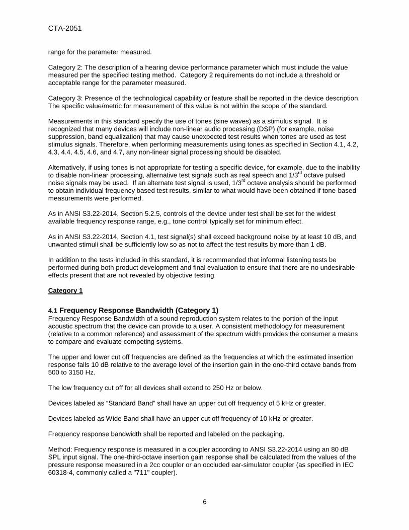
4.1 Frequency Response Bandwidth (Category 1) Frequency Response Bandwidth of a sound reproduction system relates to the portion of the input acoustic spectrum that the device can provide to a user. A consistent methodology for measurement (relative to a common reference) and assessment of the spectrum width provides the consumer a means to compare and evaluate competing systems. The upper and lower cut off frequencies are defined as the frequencies at which the estimated insertion response falls 10 dB relative to the average level of the insertion gain in the one-third octave bands from 500 to 3150 Hz. The low frequency cut off for all devices shall extend to 250 Hz or below. Devices labeled as “Standard Band” shall have an upper cut off frequency of 5 kHz or greater. Devices labeled as Wide Band shall have an upper cut off frequency of 10 kHz or greater. Frequency response bandwidth shall be reported and labeled on the packaging. Method: Frequency response is measured in a coupler according to ANSI S3.22-2014 using an 80 dB SPL input signal. The one-third-octave insertion gain response shall be calculated from the values of the pressure response measured in a 2cc coupler or an occluded ear-simulator coupler (as specified in IEC 60318-4, commonly called a "711" coupler).
6
CTA-2051
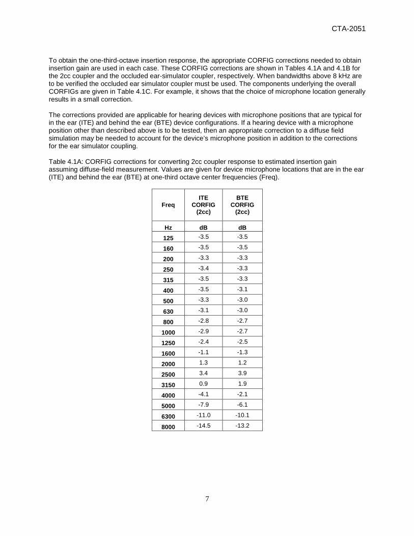
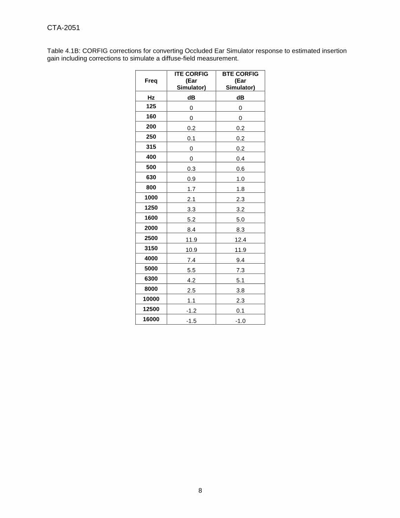
To obtain the one-third-octave insertion response, the appropriate CORFIG corrections needed to obtain insertion gain are used in each case. These CORFIG corrections are shown in Tables 4.1A and 4.1B for the 2cc coupler and the occluded ear-simulator coupler, respectively. When bandwidths above 8 kHz are to be verified the occluded ear simulator coupler must be used. The components underlying the overall CORFIGs are given in Table 4.1C. For example, it shows that the choice of microphone location generally results in a small correction. The corrections provided are applicable for hearing devices with microphone positions that are typical for in the ear (ITE) and behind the ear (BTE) device configurations. If a hearing device with a microphone position other than described above is to be tested, then an appropriate correction to a diffuse field simulation may be needed to account for the device’s microphone position in addition to the corrections for the ear simulator coupling. Table 4.1A: CORFIG corrections for converting 2cc coupler response to estimated insertion gain assuming diffuse-field measurement. Values are given for device microphone locations that are in the ear (ITE) and behind the ear (BTE) at one-third octave center frequencies (Freq).
Freq ITE
CORFIG (2cc)
BTE CORFIG
(2cc)
Hz dB dB 125 -3.5 -3.5
160 -3.5 -3.5
200 -3.3 -3.3
250 -3.4 -3.3
315 -3.5 -3.3
400 -3.5 -3.1
500 -3.3 -3.0
630 -3.1 -3.0
800 -2.8 -2.7
1000 -2.9 -2.7
1250 -2.4 -2.5
1600 -1.1 -1.3
2000 1.3 1.2
2500 3.4 3.9
3150 0.9 1.9
4000 -4.1 -2.1
5000 -7.9 -6.1
6300 -11.0 -10.1
8000 -14.5 -13.2
7
CTA-2051
Table 4.1B: CORFIG corrections for converting Occluded Ear Simulator response to estimated insertion gain including corrections to simulate a diffuse-field measurement.
Freq ITE CORFIG
(Ear Simulator)
BTE CORFIG (Ear
Simulator) Hz dB dB 125 0 0 160 0 0 200 0.2 0.2 250 0.1 0.2 315 0 0.2 400 0 0.4 500 0.3 0.6 630 0.9 1.0 800 1.7 1.8
1000 2.1 2.3 1250 3.3 3.2 1600 5.2 5.0 2000 8.4 8.3 2500 11.9 12.4 3150 10.9 11.9 4000 7.4 9.4 5000 5.5 7.3 6300 4.2 5.1 8000 2.5 3.8
10000 1.1 2.3 12500 -1.2 0.1 16000 -1.5 -1.0
8
CTA-2051
Table 4.1C: Details underlying the set of CORFIG diffuse field corrections used in Tables 4.1A and 4.1B. CORFIG formulae based on microphone location (A1 and A2), acoustic coupler (B1 and B2), and the diffuse field response of the open ear, measured at the eardrum (C). The combination of these data generate four CORFIG responses, (D1, D2, E1 and E2): D1 is the ITE, 2cc coupler CORFIG: D1 = C - B1 – A1; D2 is the BTE, 2cc coupler CORFIG: D2 = C – B1 – A2; E1 is the ITE, Occluded Ear Simulator CORFIG: E1 = C – B2 – A1; E2 is the BTE, Occluded Ear Simulator CORFIG: E2 = C – B2 – A2.
A1 A2 B1 B2 C D1 D2 E1 E2
One third octave centers
SPL increase at Microphone
location re: diffuse field SPL
SPL increase at Microphone
location re: diffuse field SPL
SPL increase at eardrum re: 2cc
coupler
SPL increase at eardrum re: ear
simulator
SPL increase at eardrum re: diffuse
field SPL 2cc Coupler
CORFIG Occluded Ear Simulator CORFIG
Freq Microphone location correction Real Ear to Coupler Difference (RECD) Diffuse Field
Response of the Open Ear ITE MIC BTE MIC 2cc Occluded Ear
Simulator ITE CORFIG BTE CORFIG ITE CORFIG BTE CORFIG
Hz dB dB dB dB dB dB dB dB dB 125 0.2 0.2 3.5 0 0.2 -3.5 -3.5 0 0 160 0.3 0.3 3.5 0 0.3 -3.5 -3.5 0 0 200 0.3 0.3 3.5 0 0.5 -3.3 -3.3 0.2 0.2 250 0.5 0.4 3.5 0 0.6 -3.4 -3.3 0.1 0.2 315 0.8 0.6 3.5 0 0.8 -3.5 -3.3 0 0.2 400 1.2 0.8 3.5 0 1.2 -3.5 -3.1 0 0.4 500 1.3 1.0 3.6 0 1.6 -3.3 -3.0 0.3 0.6 630 1.3 1.2 4.0 0 2.2 -3.1 -3.0 0.9 1.0 800 1.3 1.2 4.5 0 3.0 -2.8 -2.7 1.7 1.8 1000 1.8 1.6 5.0 0 3.9 -2.9 -2.7 2.1 2.3 1250 2.1 2.2 5.7 0 5.4 -2.4 -2.5 3.3 3.2 1600 2.4 2.6 6.3 0 7.6 -1.1 -1.3 5.2 5.0 2000 2.7 2.8 7.1 0 11.1 1.3 1.2 8.4 8.3 2500 3.3 2.8 8.5 0 15.2 3.4 3.9 11.9 12.4 3150 4.0 3.0 10.0 0 14.9 0.9 1.9 10.9 11.9 4000 5.2 3.2 11.5 0 12.6 -4.1 -2.1 7.4 9.4 5000 5.4 3.6 13.4 0 10.9 -7.9 -6.1 5.5 7.3 6300 5.0 4.1 15.2 0 9.2 -11.0 -10.1 4.2 5.1 8000 6.0 4.7 17.0 0 8.5 -14.5 -13.2 2.5 3.8 10000 5.8 4.6 0 6.9 1.1 2.3 12500 5.7 4.4 0 4.5 -1.2 0.1 16000 4.5 4.0 0 3.0 -1.5 -1.0
9

CTA-2051
4.2 Frequency Response Smoothness (Category 1) Frequency Response Smoothness of a sound reproduction system relates to user experience of fidelity or consistent performance across frequency. A limit on maximum deviation is specified to ensure that sufficient smoothness is achieved. No single peak in the one-third-octave frequency response shall exceed 12 dB relative to the average levels of the one-third-octave bands two-thirds octave above and below the peak. Example: A peak at 1.6 kHz should be compared to the average of the 1.0 kHz and 2.5 kHz one-third-octave levels. The frequency response evaluated for this parameter shall be the diffuse field corrected one-third-octave frequency insertion response as specified in 4.1.
4.3 Maximum Acoustic Output (Category 1) Maximum Acoustic Output relates to user comfort, in particular to avoid uncomfortably loud sounds. A criterion for maximum output provides a minimum performance standard for user comfort. The maximum OSPL90 output level shall not exceed 120 dB SPL measured in a 2cc coupler. Refer to ANSI S3.22-2014 for OSPL90 measurement conditions. Note: A 120 dB SPL measured in a 2cc coupler is equivalent to a level of approximately 115 dBA referred to the sound field. See Annex A for more information.
4.4 Distortion Control Limits (Category 1) Distortion relates to user experience of fidelity or faithful reproduction of the sound input. A maximum criterion for distortion provides a minimum performance standard. The minimum analyzer bandwidth for measuring THD shall be the advertised frequency limits of the device.
4.4.1 Output Distortion Using a 500 Hz tone as input, the THD+N shall not exceed 5% for outputs of 70 and 100 dB SPL. Distortion is to be measured using a 2cc coupler with the device volume control set to maximum and the input sound level to the device adjusted to give the required outputs. Note 1: If a 500 Hz 1/3rd octave pulsed-noise signal (such as that specific in IEEE-269) is used, then the tests shall be performed with output levels of 67 and 97 dB SPL (instead of 70 and 100 dB SPL used for sine wave based testing). This adjustment is made to account for the higher peak-to-rms ratio of the 1/3rd octave pulsed-noise test signal. Note 2: The source of sound can be a hearing device test box or laboratory test system.
4.4.2 Input Distortion THD+N shall not exceed 5% with a 500-Hz tone input applied to the microphone of the device at a level of 100 dB SPL. The device output shall be measured into a 2cc coupler and the volume control should be adjusted to produce an output of 80 dB SPL (unweighted). NOTE 1: If a 500 Hz 1/3rd octave pulsed-noise signal (such as that specific in IEEE-269) is used, then the signal level applied shall be 97 dB SPL. This adjustment is made to account for the higher peak-to-rms ratio of the 1/3rd octave pulsed-noise test signal.
10
CTA-2051
NOTE 2: A 100 dB SPL-rms sine wave has a 103 dB peak which corresponds to approximately 90 dB SPL-rms speech and music as measured with a sound level meter (Fast).
4.5 Self-generated Noise Levels (Category 1) Self-generated noise relates to noise at the device output that is not present in the input sound. Such noise can potentially mask soft but desirable sounds. A criterion for maximum self-generated noise provides a minimum performance standard. Self-generated noise shall not exceed 32 dBA (equivalent SPL) referred to the input. Output shall be measured in a 2cc coupler. Methods that artificially lower the apparent noise floor (e.g., auto-muting, downward expansion) shall be disabled during testing. Category 2 4.6 High Frequency Gain Provided (Category 2) The manufacturer shall report the maximum available high-frequency gain. This gain is the average of the 2 cc coupler gains at 1.0, 1.6, and 2.5 kHz, measured as per ANSI S3.22-2014 with 50 dB SPL input.
4.7 Battery Life (Category 2) Battery life is directly related to user experience, expectations, and operating cost. Establishment of a common metric for battery life allows customers to more accurately evaluate and compare devices. Manufacturers shall report the estimated battery life for a single operating charge cycle with all optional features turned on and report the estimated battery life for a single operating charge cycle with all optional features turned off. This would be the time that a single use battery would require replacement or the time required before a rechargeable battery would need to be recharged. If the battery is replaceable, the recommended battery type shall be specified. Estimated battery life in each case is to be calculated from the minimum mAh capacity rating of the manufacturer recommended battery divided by the current draw under the stated measurement conditions. Measurement conditions: Input signal: 1 KHz tone at 65 dB SPL
(measured at the microphone or equivalent direct input) Volume control: Adjust for 85 dB SPL in coupler, or maximum volume control
setting Tone control: Adjust for widest frequency response possible AGC & noise/feedback suppression: Disable/adjust for minimum effect (where possible)
(includes compression & expansion)
Where device function is limited by a minimum voltage requirement* that exceeds the battery rated full discharge voltage, the capacity rating shall be de-rated to coincide with the minimum required operating voltage on the typical battery discharge curve for the current discharge rate. * or onset of low battery warning/indication.
11

CTA-2051
4.8 Latency (Category 2) Latency relates to user experience of temporal fidelity or time alignment of the reproduced sound with the original. The critical aspect of latency relates to the perception of one’s own voice when speaking, whereby the signal from the device interacts with one’s voice heard naturally through bone and air conduction. Excess latency tends to inhibit speech. Latency should not exceed 15 ms.
There are multiple acceptable methods for determining latency. One method is to use a 100 Hz square wave signal wherein the time difference between the leading edges of the input and output waveforms can be observed on an oscilloscope. Another approach is to compare the peak arrival times of the input and output impulse responses. Other approaches are acceptable as well so long as they are accurate and repeatable within 1.5 ms.
4.9 RF-Immunity (Category 2) The manufacturer shall report RF Immunity for wireless device compatibility in both microphone (M) and, if present, telecoil (T) coupling modes. Immunity shall be measured in accordance with ANSI C63.19-2011 and the M and T ratings reported. An immunity of M2/T2 or better is recommended. Category 3
4.10 Fixed or Level Dependent Frequency Equalization - Tone Control (Category 3) Manufacturers shall report if device tone controls are present and, if so, how they operate. Some tone controls enable a user to adjust the frequency response which is then fixed independent of level. Others change the frequency response versus input level without user interaction, i.e., automatically according to the manufacturer’s algorithm. Combinations of the above also exist.
4.11 Level Dependent Gain/Compression (Category 3) Manufacturers should provide qualitative information identifying the functional compression/automatic gain of the device. This description should classify the compression/automatic gain characteristic(s) of the device as Multiband, Single Band, or none (Linear) and whether it is Wide Dynamic Range Compression and/or Limiting.
4.12 SNR Enhancement (Category 3) Directional and remote microphones can enhance the level of a desired sound source (e.g., a preferred talker) relative to background noise or the sound from other sources in the environment. Manufacturers shall report the presence of an omnidirectional microphone, directional microphone, and/or remote microphone (if available).
4.13 Noise Reduction (Category 3) Beyond the techniques in Section 4.12, other noise-reduction algorithms exist that attempt to mitigate the deleterious effects of noise while minimizing degradation of a desired signal. The manufacturer shall report whether a noise reduction feature is included.
4.14 Feedback Control / Cancellation (Category 3) The manufacturer will indicate whether feedback control/cancellation signal processing is included.
12
CTA-2051
4.15 Personalization (Category 3) 4.15.1 General Current and future technological development may benefit from methods to introduce personalization into the device tuning or functionality. Forms of personalization may be derived from standard referenced psychophysical methodologies or novel proprietary methods. Personal response characteristics which modify the device functionality that may be of benefit to the user include, but are not limited to: a user’s hearing thresholds as a function of frequency, hearing performance in various conditions of noise, speech intelligibility in noise, localization resolution, or head-related transfer function specification. Future identified relevant personal response characteristics that improve device functionality for the user should be able to be rapidly introduced into devices whose performance specification is captured by this standard. 4.15.2 Specification and Reporting While personalization is not a requirement for compliance with this standard, compliance does require reporting a description of any personalized device functionality. This functionality should be described in a way that a user may be able to identify common elements of device personalization across multiple market offerings. For example, a user should be easily able to differentiate between devices that make use of their hearing thresholds from those that do not. The general method for determination of the specific personalized response characteristic that is modifying performance of a particular device should be described or a reference provided.
4.16 Device Coupling to the Ear (Category 3) The manufacturer shall report the fit of the device to the user’s ear using the following definitions:
• Open fit – The ear is open to receive sound from the combination of the natural acoustic environmental sounds and electro-acoustically amplified sounds provided from the device.
• Closed fit –The ear is occluded. The ear primarily receives electro-acoustically amplified sounds provided from the device.
• Adjustable fit – The user can adjust the degree of occlusion to the ear. This provides user control between the amount of natural acoustic environmental sounds and the amount of electro-acoustic amplification provided from the device.
4.17 Wireless Connectivity (Category 3) The manufacturer shall report all modes of wireless connectivity supported by the device, for example: none, telecoil, Bluetooth, DECT, Wi-Fi, etc. 5 Reporting The manufacturer shall provide specific information that is readily available to a potential consumer at the point of purchase. The following information shall be included: frequency response bandwidth (see section 4.1), maximum output level (see section 4.3), and a URL with data for all parameters measured and features defined in Section 4.
13
CTA-2051
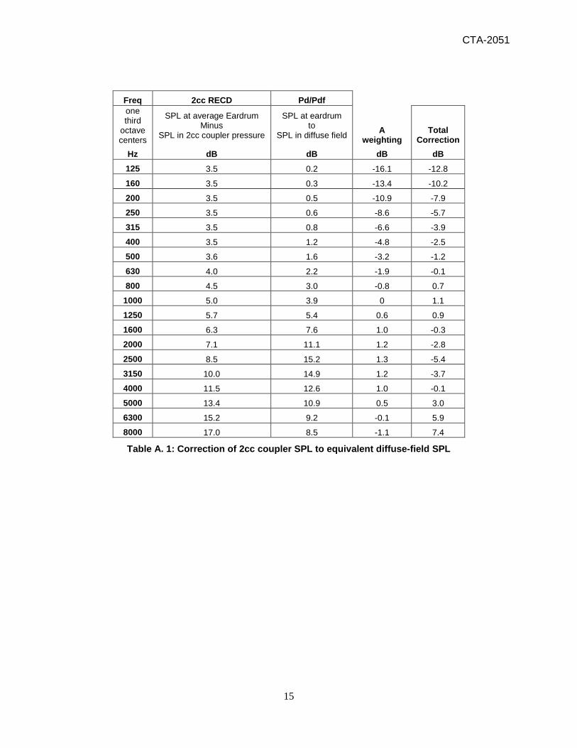
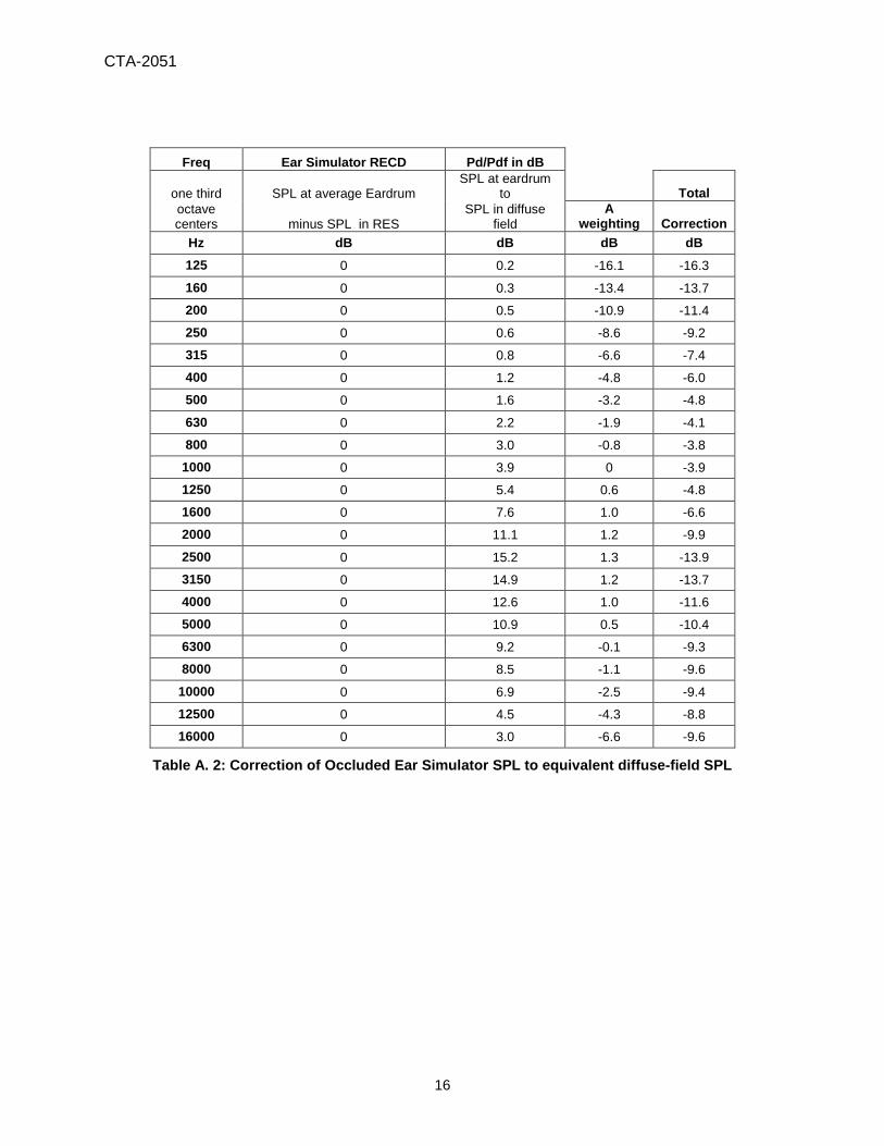
Annex A: Maximum Acoustic Output In the design of any device reproducing live sound there is a required development balance to provide undistorted reproduction of content such as live music while at the same time avoiding sudden peak output SPLs which would be uncomfortable to the listener. To optimize this balance, a maximum output level of 120 dB is recommended. The National Institute for Occupational Safety and Health (NIOSH) describes in the standard NIOSH-98 that a 115 dBA SPL sound field is an acceptable listening level for up to 30 seconds. As shown in Table A.1, a 120 dB SPL sound measured in a 2cc coupler is equivalent to a level of approximately 115 dBA for a measured sound field. A device with this maximum output should provide the user sufficient time to turn it off or remove it from the ear before it reaches an unacceptable level. However, it is important to recognize that a maximum undistorted output below the levels described above may be inadequate for reproduction of some sounds listeners wish to hear such as unamplified music. For example, the sound level of live symphonies has been measured (C-weighting, Fast) with peak readings of at least 104-106 dB SPL from mid-audience range in a concert hall. To assure that these real-life sonic events, such as the example symphony, are as faithfully represented as possible, a maximum output level of 120 dB is recommended. A maximum output level of 120 dB (after conversion to equivalent sound field values) should prevent output clipping distortion and support reproduction of the occasional peaks that a listener would want to hear free of distortion. The following tables capture some relevant equivalencies between measured sound fields and the corresponding output levels for different measurement capture systems. For example, a pure-tone sound field level of 117 dB SPL at 2 kHz corresponds to an output of 120 dB SPL as measured in a 2cc coupler (Table A.1) or an output of 124.9 dB SPL as measured in an occluded ear simulator (Table A.2). Tables A.1 and A.2 first convert to the corresponding sound field SPL and then add the A-weighting correction (1.2 dB at 2 kHz) to transfer the final number to what would be measured in the sound field with a typical sound level meter that reports in dBA.
14
CTA-2051
Freq 2cc RECD Pd/Pdf one
third octave centers
SPL at average Eardrum Minus
SPL in 2cc coupler pressure
SPL at eardrum to
SPL in diffuse field A weighting
Total Correction
Hz dB dB dB dB 125 3.5 0.2 -16.1 -12.8
160 3.5 0.3 -13.4 -10.2
200 3.5 0.5 -10.9 -7.9
250 3.5 0.6 -8.6 -5.7
315 3.5 0.8 -6.6 -3.9
400 3.5 1.2 -4.8 -2.5
500 3.6 1.6 -3.2 -1.2
630 4.0 2.2 -1.9 -0.1
800 4.5 3.0 -0.8 0.7
1000 5.0 3.9 0 1.1
1250 5.7 5.4 0.6 0.9
1600 6.3 7.6 1.0 -0.3
2000 7.1 11.1 1.2 -2.8
2500 8.5 15.2 1.3 -5.4
3150 10.0 14.9 1.2 -3.7
4000 11.5 12.6 1.0 -0.1
5000 13.4 10.9 0.5 3.0
6300 15.2 9.2 -0.1 5.9
8000 17.0 8.5 -1.1 7.4
Table A. 1: Correction of 2cc coupler SPL to equivalent diffuse-field SPL
15
CTA-2051
Freq Ear Simulator RECD Pd/Pdf in dB
one third SPL at average Eardrum SPL at eardrum
to
Total octave centers minus SPL in RES
SPL in diffuse field
A weighting Correction
Hz dB dB dB dB 125 0 0.2 -16.1 -16.3
160 0 0.3 -13.4 -13.7
200 0 0.5 -10.9 -11.4
250 0 0.6 -8.6 -9.2
315 0 0.8 -6.6 -7.4
400 0 1.2 -4.8 -6.0
500 0 1.6 -3.2 -4.8
630 0 2.2 -1.9 -4.1
800 0 3.0 -0.8 -3.8
1000 0 3.9 0 -3.9
1250 0 5.4 0.6 -4.8
1600 0 7.6 1.0 -6.6
2000 0 11.1 1.2 -9.9
2500 0 15.2 1.3 -13.9
3150 0 14.9 1.2 -13.7
4000 0 12.6 1.0 -11.6
5000 0 10.9 0.5 -10.4
6300 0 9.2 -0.1 -9.3
8000 0 8.5 -1.1 -9.6
10000 0 6.9 -2.5 -9.4
12500 0 4.5 -4.3 -8.8
16000 0 3.0 -6.6 -9.6
Table A. 2: Correction of Occluded Ear Simulator SPL to equivalent diffuse-field SPL
16

Consumer Technology Association Document Improvement Proposal
If in the review or use of this document a potential change is made evident for safety, health or technical reasons, please email your reason/rationale for the recommended change to [email protected].
Consumer Technology Association Technology & Standards Department
1919 S Eads Street, Arlington, VA 22202 FAX: (703) 907-7693 [email protected]