ANSI/ASHRAE Standard 140-2004 Building Thermal … · ASHRAE 140 Envelope Tests 2 17 June 2006 1.0...
50
ANSI/ASHRAE Standard 140-2004 Building Thermal Envelope and Fabric Load Tests DesignBuilder Version 1.2.0 (incorporating EnergyPlus version 1.3.0) - June 2006
Transcript of ANSI/ASHRAE Standard 140-2004 Building Thermal … · ASHRAE 140 Envelope Tests 2 17 June 2006 1.0...

ANSI/ASHRAE Standard 140-2004 Building Thermal Envelope and Fabric Load Tests
DesignBuilder Version 1.2.0 (incorporating EnergyPlus version 1.3.0) - June 2006

ASHRAE 140 Envelope Tests 2 17 June 2006
1.0 Purpose
The ANSI/ASHRAE Standard 140-20041 specifies test procedures that can be applied
to evaluate the range of applicability and capability of software designed to calculate
the thermal performance of buildings and their environmental control systems. The
tests are based on the principle of comparing the performance of one program against
the performance of other programs and while the tests are not intended to evaluate all
aspects of the software, they are designed to indicate any serious flaws or limitations.
Interested readers are advised to refer to the standard itself for more information.
The tests as applied to DesignBuilder have three main objectives:
• To indicate the relative performance of DesignBuilder compared with various
other state-of-the-art building energy computer programs.
• To compare the results from EnergyPlus (v 1.3.0) run from within
DesignBuilder with the results taken from the GARD Analytics report2 on
EnergyPlus (v 1.3.0) run in standalone mode.
• To allow future versions of DesignBuilder to be compared with previous
versions as part of the DesignBuilder Quality Assurance procedure.

ASHRAE 140 Envelope Tests 3 17 June 2006
2.0 Building Thermal Envelope and Fabric Load Test Cases
The thermal envelope and fabric load test cases are divided into three main groups.
The first group is designed to test the software using a low mass configuration, the
second using high mass and the third group tests both low and high mass
configurations under free float conditions.
The following test cases were performed as specified in the standard:
• Base test case 600 (Section 5.2.1 of Standard)
• Basic tests (Section 5.2.2 of Standard)
Low mass test cases 610-650.
High mass test cases 900-960
Free-float test cases 600FF, 650FF, 900FF and 950FF
Modelling requirements specific to DesignBuilder are detailed in Section 2.5.
2.1 Common Input Information
This section describes input data that is common to all test cases.
2.1.1 Window Properties
Property Value
Extinction coefficient 0.0196/mm
Number of panes 2
Pane thickness 3.175 mm
Air-gap thickness 13 mm
Index of refraction 1.526
Normal direct-beam transmittance through one pane 0.86156
Thermal conductivity of glass 1.06 W/mK
Conductance of each glass pane 333 W/m2K
Combined radiative and convective coefficient of air gap 6.297 W/m2K
Exterior combined surface coefficient 21.00 W/m2K
Interior combined surface coefficient 8.29 W/m2K
U-value from interior air to ambient air 3.0 W/m2K
Hemispherical infrared emittance of ordinary uncoated glass 0.9
Density of glass 2500 kg/m3
Specific heat of glass 750 J/kgK
Interior shade devices None
Double-pane shading coefficient at normal incidence 0.907
Double-pane solar heat gain coefficient at normal incidence 0.789

ASHRAE 140 Envelope Tests 4 17 June 2006
EnergyPlus uses the Windows 5 format for the specification of window properties and
additional glass properties are required for the inside and outside surfaces. These
additional properties have been obtained from the GARD Analytics report2:
Thermal Properties
Property Value
Thickness 3.175 mm
Conductivity 1.060 W/mK
Solar Properties
Property Value
Solar transmittance 0.86156
Outside solar reflectance 0.07846
Inside solar reflectance 0.07846
Visible Properties
Property Value
Visible transmittance 0.91325
Outside visible reflectance 0.08200
Inside visible reflectance 0.08200
Infra-Red Properties
Property Value
Infra-red transmittance 0.00000
Outside infra-red reflectance 0.84000
Inside infra-red reflectance 0.84000
2.1.2 Weather
The weather file used is the DRYCOLD.TMY file supplied with the ASHRAE
Standard1.
2.1.3 Infiltration
The infiltration rate used for all test cases considered is 0.5 a.c./hr unless otherwise
stated.
2.1.4 Internally Generated Heat
Internal heat gains generated by lights, occupants, equipment, etc.are set at 200W.
Heat gains have no latent content and have a 60% radiant fraction.

ASHRAE 140 Envelope Tests 5 17 June 2006
2.1.5 Mechanical System
The mechanical system for each test case for which heating or cooling is specified has
the following properties unless otherwise stated:
• 100% convective air system
• Thermostat senses air temperature only
• No latent load
• Thermostat is non-proportional
• Thermostat has dual setpoint with deadband, heating < 20C, cooling > 27C
2.1.6 Ground Temperature
The soil temperature is a constant 10C.
2.2 Low Mass Test Cases
The low mass test case constructions are detailed below:
Low Mass Wall Construction (inside to outside)
Element k
(W/mK)
Thickness
(m)
U
(W/m2K)
R
(m2K/W)
Density
(kg/m3)
Cp
(J/kgK)
Int.Surface Coeff. 8.290 0.121
Plasterboard 0.160 0.012 13.333 0.075 950.000 840.000
Fibreglass Quilt 0.040 0.066 0.606 1.650 12.000 840.000
Wood Siding 0.140 0.009 15.556 0.064 530.000 900.000
Ext.Surface Coeff. 29.300 0.034
Total air-air 0.514 1.944
Total surf-surf 0.559 1.789
Low Mass Floor Construction (inside to outside)
Element k
(W/mK)
Thickness
(m)
U
(W/m2K)
R
(m2K/W)
Density
(kg/m3)
Cp
(J/kgK)
Int.Surface Coeff. 8.290 0.121
Timber Flooring 0.140 0.025 5.600 0.179 650.000 1200.000
Insulation 0.040 1.003 0.040 25.075 12.000 840.000
Total air-air 0.039 25.374
Total surf-surf 0.040 25.254

ASHRAE 140 Envelope Tests 6 17 June 2006
Low Mass Roof Construction (inside to outside)
Element k
(W/mK)
Thickness
(m)
U
(W/m2K)
R
(m2K/W)
Density
(kg/m3)
Cp
(J/kgK)
Int.Surface Coeff. 8.290 0.121
Plasterboard 0.160 0.010 16.000 0.063 950.000 840.000
Fibreglass Quilt 0.040 0.1118 0.358 2.794 12.000 840.000
Roof Deck 0.140 0.019 7.368 0.136 530.000 900.000
Ext.Surface Coeff. 29.300 0.034
Total air-air 0.318 3.147
Total surf-surf 0.334 2.992
2.2.1 Low Mass Basic Test Case 600
Test case 600 comprises a single rectangular lightweight zone the dimensions of
which are 8m x 6m x 2.7m. The zone is not partitioned and is fitted with two 6 m2
windows in the south facing wall:

ASHRAE 140 Envelope Tests 7 17 June 2006
2.2.2 Low Mass with South Shading – Test Case 610
Test case 610 is the same as test case 600 with the addition of a 1m horizontal
overhang that runs across the entire length of the south-facing wall at roof level:
2.2.3 Low Mass with East-West Window Orientation – Test Case 620
Test case 620 is the same as test case 600 except that the south-facing windows are
removed and 6m2 of window area is added to the east and west facades:

ASHRAE 140 Envelope Tests 8 17 June 2006
2.2.4 Low Mass with East-West Shading – Test Case 630
Test case 630 is the same as test case 620 with the addition of shading overhangs and
side fins around the east and west-facing windows. A 1m overhang is located at roof
level and extends across the 3m width of each window. A 1m deep side fin is located
at the side edges of each window running from the roof level down to the ground:
2.2.5 Low Mass with Thermostat Setback – Test Case 640
Test case 640 is the same as test case 600 except that the following setpoint schedule
is used:
• 2300-0700 hours: heating ON if inside temperature < 10C
• 0700-2300 hours: heating ON if inside temperature < 20C
• 0000-2300 hours: cooling ON if inside temperature > 27C
• Otherwise heating and cooling is OFF
2.2.6 Low Mass with Night Ventilation – Test Case 650
Test case 650 is the same as test case 600 except that the following nighttime
ventilation schedule and heating/cooling setpoint schedules are used:
• 1800-0700 hours: ventilation fan is ON
• 0700-1800 hours: ventilation fan is OFF
• 0000-2300 hours: heating is OFF
• 0070-1800 hours: cooling ON if inside temperature > 27C, otherwise cooling
is OFF
• 1800-0700 cooling is OFF

ASHRAE 140 Envelope Tests 9 17 June 2006
The ventilation fan capacity is 13.14 ac/hr and there is no heat exchange from the fan
to the supply air.
2.3 High Mass Test Cases
The high mass test case constructions are detailed below:
High Mass Wall Construction (inside to outside)
Element k
(W/mK)
Thickness
(m)
U
(W/m2K)
R
(m2K/W)
Density
(kg/m3)
Cp
(J/kgK)
Int.Surface Coeff. 8.290 0.121
Concrete Block 0.510 0.1000 5.100 0.196 1400.00 1000.00
Foam Insulation 0.040 0.0615 0.651 1.537 10.00 1400.00
Wood Siding 0.140 0.0090 15.556 0.064 530.00 900.00
Ext.Surface Coeff. 29.300 0.034
Total air-air 0.512 1.952
Total surf-surf 0.556 1.797
High Mass Floor Construction (inside to outside)
Element k
(W/mK)
Thickness
(m)
U
(W/m2K)
R
(m2K/W)
Density
(kg/m3)
Cp
(J/kgK)
Int.Surface Coeff. 8.290 0.121
Concrete Slab 1.130 0.080 14.125 0.071 1400.00 1000.00
Insulation 0.040 1.007 0.040 25.175
Total air-air 0.039 25.366
Total surf-surf 0.040 25.246
High Mass Roof Construction (inside to outside)
Element k
(W/mK)
Thickness
(m)
U
(W/m2K)
R
(m2K/W)
Density
(kg/m3)
Cp
(J/kgK)
Int.Surface Coeff. 8.290 0.121
Plasterboard 0.160 0.010 16.000 0.063 950.000 840.000
Fibreglass Quilt 0.040 0.1118 0.358 2.794 12.000 840.000
Roof Deck 0.140 0.019 7.368 0.136 530.000 900.000
Ext.Surface Coeff. 29.300 0.034
Total air-air 0.318 3.147
Total surf-surf 0.334 2.992
2.3.1 High Mass Basic Test Case 900
The basic high mass test case uses the same building model as the low mass basic test
case 600 except the construction of the walls and floor are modified to incorporate the
higher mass materials.
ASHRAE 140 Envelope Tests 10 17 June 2006
2.3.2 High Mass with South Shading – Test Case 910
Test case 910 is the same as the low mass test case 610 except for the high mass
construction specified for the walls and floor.
2.3.3 High Mass with East-West Window Orientation – Test Case 920
Test case 920 is the same as the low mass test case 620 except for the high mass
construction specified for the walls and floor.
2.3.4 High Mass with East-West Shading – Test Case 930
Test case 930 is the same as the low mass test case 630 except for the high mass
construction specified for the walls and floor.
2.3.5 High Mass with Thermostat Setback – Test Case 940
Test case 940 is the same as the low mass test case 640 except for the high mass
construction specified for the walls and floor.
2.3.6 High Mass with Night Ventilation – Test Case 950
Test case 950 is the same as the low mass test case 650 except for the high mass
construction specified for the walls and floor.
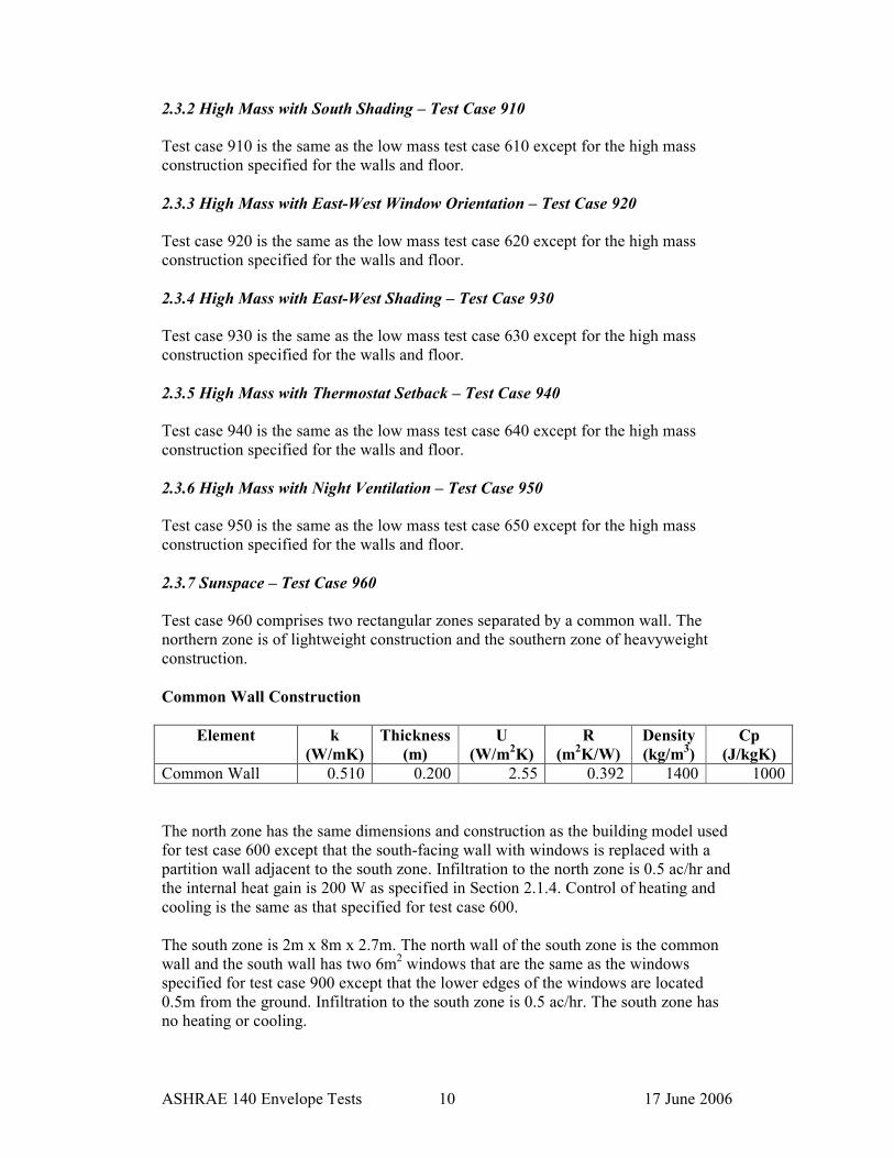
2.3.7 Sunspace – Test Case 960
Test case 960 comprises two rectangular zones separated by a common wall. The
northern zone is of lightweight construction and the southern zone of heavyweight
construction.
Common Wall Construction
Element k
(W/mK)
Thickness
(m)
U
(W/m2K)
R
(m2K/W)
Density
(kg/m3)
Cp
(J/kgK)
Common Wall 0.510 0.200 2.55 0.392 1400 1000
The north zone has the same dimensions and construction as the building model used
for test case 600 except that the south-facing wall with windows is replaced with a
partition wall adjacent to the south zone. Infiltration to the north zone is 0.5 ac/hr and
the internal heat gain is 200 W as specified in Section 2.1.4. Control of heating and
cooling is the same as that specified for test case 600.
The south zone is 2m x 8m x 2.7m. The north wall of the south zone is the common
wall and the south wall has two 6m2 windows that are the same as the windows
specified for test case 900 except that the lower edges of the windows are located
0.5m from the ground. Infiltration to the south zone is 0.5 ac/hr. The south zone has
no heating or cooling.

ASHRAE 140 Envelope Tests 11 17 June 2006
2.4 Free Float Test Cases
There are four free float test cases incorporating both lightweight and heavyweight
constructions.
2.4.1 Low Mass with Free Floating Temperature – Test Case 600FF
Test case 600FF is the same as test case 600 except that there is no mechanical
heating or cooling.
2.4.2 Low Mass with Night Ventilation and Free Floating Temperature – Test Case
650FF
Test case 650FF is the same as test case 650 except that there is no mechanical
heating or cooling.
2.4.3 High Mass with Free Floating Temperature – Test Case 900FF
Test case 900FF is the same as test case 900 except that there is no mechanical
heating or cooling.
2.4.4 High Mass with Night Ventilation and Free Floating Temperature – Test Case
950FF
Test case 950FF is the same as test case 950 except that there is no mechanical
heating or cooling.

ASHRAE 140 Envelope Tests 12 17 June 2006
2.5 Modelling Notes
Model geometry is defined in DesignBuilder by drawing the external dimensions of a
building rather than the internal dimensions of the contained zones and this is
accounted for in the specification of the test case geometry. Also, due to the fact that
different programs have different input requirements there are some items of data
provided by the standard that are not required by DesignBuilder. This section details
various modelling considerations that are specific to DesignBuilder in preparation of
the test case input data. Some of the input data that is specific to EnergyPlus has been
extracted from the GARD Analytics report2.
2.5.1 Geometry
DesignBuilder geometry is based on the concept of blocks. A building block
represents the outer shell of the model or part of the model and comprises a set of
building elements, which includes external walls, roof, and floor slab. A vertically
extruded block is created in DesignBuilder by drawing the external perimeter of the
outer wall. The resulting internal zone perimeter is the same as the external block
perimeter but shrunk by the defined thickness of the external wall. The user-defined
block wall thickness only affects the resulting zone dimensions and has no effect on
the thermal properties of the walls. The resulting zone upper and lower surfaces
correspond identically with the upper and lower block surfaces.
For simplicity, in order to arrive at the correct zone geometry for the tests, the wall
thickness was set at 0.1m and 0.2m added on to the specified plan zone dimensions.
For example, the base test case 600 has the specified dimensions of 8m x 6m x 2.7m
and in DesignBuilder the block dimensions are 8.2m x 6.2m x 2.7m.
2.5.2 Material Specification
Materials for walls floors and roofs were specified using the ‘Detailed’ material
description except for floor insulation, which was defined through specification of
ground materials using the ‘Resistance’ option.
Both low and high mass test cases incorporate floor constructions that include a thick
layer of insulation to effectively decouple the floor from the ground. The ASHRAE
standard1 incorporates this specification in recognition of the fact that the state-of-the-
art in ground modelling is not good.
Ground thermal properties are always included with ground floor constructions in
DesignBuilder and are specified as a separate construction. In order to arrive at the
floor specifications provided by the standard, the ground construction materials were
defined to have the same thermal properties as the insulating layers and then the floor
constructions were defined excluding these layers.

ASHRAE 140 Envelope Tests 13 17 June 2006
2.5.3 HVAC System
The ‘Simple’ HVAC system option was selected from the DesignBuilder ‘Model
Options’ which uses the 100% convective PURCHASED AIR system in EnergyPlus.
At the Zone level, the plant capacities were set to 1000kW for both heating and
cooling to simulate infinite capacity. System efficiencies (COP) for both heating and
cooling were set to 1.0.
2.5.4 Surface heat transfer coefficients
EnergyPlus automatically calculates surface heat transfer coefficients. The ASHRAE
standard1 specifies that where a program automatically calculates these coefficients,
then they should be derived by the program rather than taken from the standard.
2.5.5 Calculation Options
This section details specifications for the simulation.

ASHRAE 140 Envelope Tests 14 17 June 2006
a) Convergence
The convergence variables were set as follows:
• Loads Convergence=0.0040
• Temperature Convergence=0.040
b) Solar Distribution
In order to calculate the correct solar distribution for the window overhang test
cases, the solar distribution option was set to ‘Full interior and exterior’.
c) Time Steps
The number of time steps per hour was set to 4.
d) Convection Algorithms
The inside and outside convection algorithms were set to ‘Detailed’.

ASHRAE 140 Envelope Tests 15 17 June 2006
2.5.6 Weather
The weather file to be used for all test case simulations is provided with the ASHRAE
standard1 in the form of a TMY format file. This file was first translated to the
EnergyPlus EPW format using the conversion utility incorporated within
DesignBuilder.

ASHRAE 140 Envelope Tests 16 17 June 2006
3.0 Results and Discussion
The test results are presented in Appendix I as tables and in Appendix II in the form
of charts. Details of the programs for which results are provided with the ASHRAE
standard1 are given in the table below.
Program Developer Implemented by
BLAST-3.0 level 193 v1
CERL, U.S. NREL, U.S.
Politecnico, Torino, Italy
DOE2.ID 14 LANL/LBL, U.S. NREL, U.S.
ESP-RV8 Strathclyde University,
U.K.
De Montfort University,
U.K.
SERIRES/SUNCODE 5.7 NREL/Ecotope, U.S. NREL, U.S.
SERIRES 1.2 NREL, U.S.
BRE, U.K.
BRE, U.K.
S3PAS University of Sevilla,
Spain
University of Sevilla, Spain
TASE Tampere University,
Finland
Tampere University, Finland
TRNSYS 13.1 LANL/LBL U.S. GARD Analytics, U.S.
using NREL input files
Test results for EnergyPlus have been extracted from the report provided by GARD
Analytics2. EnergyPlus has been developed by the U.S. Department of Energy.
One of the main purposes of the tests as applied to DesignBuilder was to check the
results from DesignBuilder against the results from EnergyPlus run in standalone
mode. For all 67 comparisons comprising annual heating and cooling, peak heating
and cooling and free float temperatures, the results from EnergyPlus (standalone) and
DesignBuilder are identical.
The charts in Appendix II display comparative results for annual heating, annual
cooling, peak heating and peak cooling. For the 52 individual comparisons performed,
all results for EnergyPlus (standalone) and DesignBuilder are within the range of
results from other programs with the following exceptions:
Test Output Range from
Other Programs
EnergyPlus/
DesignBuilder
630 Annual Heating 5.05 to 6.47 4.95
640 Peak Heating 5.23 to 5.91 7.34
910 Annual Heating 1.58 to 2.82 1.52
920 Annual Heating 3.31 to 4.25 3.20
930 Annual Heating 4.14 to 5.34 4.05

ASHRAE 140 Envelope Tests 17 17 June 2006
For the free floating test cases shown in Appendix III, where an additional 15
comparisons were made, all results for EnergyPlus (standalone) and DesignBuilder
are again within the range of results from other programs with the following
exceptions:
Test Output Range from
Other Programs
EnergyPlus/
DesignBuilder
600FF Maximum Zone Temperature 64.9 to 69.5 64.6
650FF Maximum Zone Temperature 63.2 to 68.2 62.8
650FF Minimum Zone Temperature -23.0 to-21.0 -23.1
950FF Minimum Zone Temperature -20.2 to -17.8 -20.4
960FF Maximum Zone Temperature 48.9 to 51.0 51.7
The charts in Appendix IV display comparative sensitivity of the various programs to
changes in building specification including increased mass, different window
orientation, windows with and without shading, etc. Sensitivity comparisons indicate
a significant difference between EnergyPlus/DesignBuilder results and the other
program results for the test cases indicated in the table below.
Test Output Range from
Other Programs
EnergyPlus/
DesignBuilder
640-600 Peak Heating 1.55 to 2.60 3.5
650-600 Annual Cooling -1.42 to –1.24 -1.65
920-900 Annual Cooling -0.356-0.018 0.086
GARD Analytics2 has indicated that further testing will be conducted on EnergyPlus
to determine the reasons for the difference in results for all test cases showing a
departure from the range of other program results.

ASHRAE 140 Envelope Tests 18 17 June 2006
4.0 Conclusion
DesignBuilder Version 1.2.0 was used to simulate a number of building test cases
specified within the ANSI/ASHRAE Standard 140-2004 ‘Standard Method of Test for
the Evaluation of Building Energy Analysis Computer Programs’. The test cases
incorporated both low and high mass constructions, windows of differing orientations,
windows with and without external shading, heating with and without night setback,
cooling with and without night ventilation and free floating temperature conditions.
Annual and peak heating and cooling energy requirements were predicted for thirteen
different test cases using DesignBuilder and the results were compared with the
results for EnergyPlus Version 1.3.0 run in standalone mode together with results
from eight other building energy simulation programs. The maxim, minimum and
average free-floating temperatures were also compared for four additional test cases.
All results for DesignBuilder were found to be identical to the results extracted from
the GARD Analytics report2 for EnergyPlus run in standalone mode. For further
information regarding the standalone EnergyPlus tests, interested readers are advised
to refer to the GARD Analytics report2.

ASHRAE 140 Envelope Tests 19 17 June 2006
5.0 References
1 ANSI/ASHRAE 2004. Standard 140-2004, Standard Method of Test for the
evaluation of Building Energy Analysis Computer Programs.
2. EnergyPlus Testing with Building Thermal Envelope and Fabric Load Tests
from ANSI/ASHRAE Standard 140-2004 – GARD Analytics, February 2006

Appendix I
Comparison Tables

Low Mass Heating and Cooling
Test Case 600 610 620 630 640 650
Annual Heating (MWh)
Minimum 4.298 4.355 4.613 5.050 2.751 0.000
Maximum 5.709 5.786 5.944 6.469 3.803 0.000
Average 5.08 5.140 5.410 5.810 3.217 0.000
EnergyPlus 4.498 4.530 4.651 4.951 2.914 0.000
DesignBuilder 4.498 4.530 4.651 4.951 2.914 0.000
Difference, % -11.5% -11.9% -14.0% -14.8% -9.4% 0.000%
EnergyPlus/DesignBuilder within Range YES YES YES NO YES YES
Annual Cooling (MWh)
Minimum 6.137 3.915 3.417 2.129 5.952 4.816
Maximum 7.964 5.778 5.004 3.701 7.811 6.545
Average 6.900 4.935 4.250 2.901 6.663 5.546
EnergyPlus 6.918 4.900 4.351 2.933 6.619 5.395
DesignBuilder 6.918 4.900 4.351 2.933 6.619 5.395
Difference, % 0.26% -0.71% 2.38% 1.1% -0.07% -2.7%
EnergyPlus/DesignBuilder within Range YES YES YES YES YES YES
Peak Heating (kW)
Minimum 3.437 3.437 3.591 3.592 5.232 0.000
Maximum 4.258 4.258 4.277 4.280 6.530 0.000 Average 3.943 3.941 4.026 4.023 5.908 0.000
EnergyPlus 3.834 3.821 3.831 3.805 7.312 0.000
DesignBuilder 3.834 3.821 3.831 3.805 7.312 0.000
Difference, % -2.76% -3.04% -4.8% -5.42% 23.8% 0.000%
EnergyPlus/DesignBuilder within Range YES YES YES YES NO YES
Peak Cooling (kW)
Minimum 5.965 5.669 3.634 3.072 5.892 5.831
Maximum 6.827 6.371 4.593 4.116 6.776 6.671
Average 6.386 6.020 4.206 3.629 6.331 6.238
EnergyPlus 6.629 6.271 4.008 3.459 6.561 6.417
DesignBuilder 6.629 6.271 4.008 3.459 6.561 6.417
Difference, % 3.80% 4.17% -4.7% -4.68% 3.63% 2.87%
EnergyPlus/DesignBuilder within Range YES YES YES YES YES YES
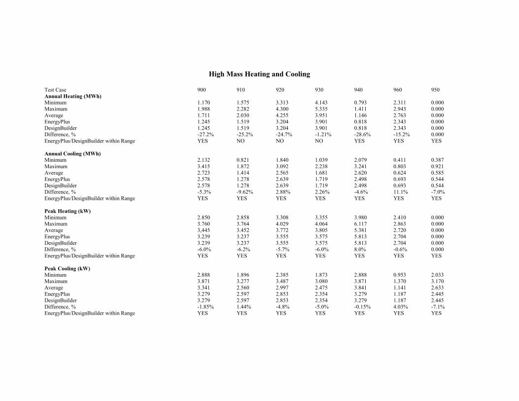
High Mass Heating and Cooling
Test Case 900 910 920 930 940 960 950
Annual Heating (MWh)
Minimum 1.170 1.575 3.313 4.143 0.793 2.311 0.000
Maximum 1.988 2.282 4.300 5.335 1.411 2.943 0.000
Average 1.711 2.030 4.255 3.951 1.146 2.763 0.000
EnergyPlus 1.245 1.519 3.204 3.901 0.818 2.343 0.000
DesignBuilder 1.245 1.519 3.204 3.901 0.818 2.343 0.000
Difference, % -27.2% -25.2% -24.7% -1.21% -28.6% -15.2% 0.000
EnergyPlus/DesignBuilder within Range YES NO NO NO YES YES YES
Annual Cooling (MWh)
Minimum 2.132 0.821 1.840 1.039 2.079 0.411 0.387
Maximum 3.415 1.872 3.092 2.238 3.241 0.803 0.921
Average 2.723 1.414 2.565 1.681 2.620 0.624 0.585
EnergyPlus 2.578 1.278 2.639 1.719 2.498 0.693 0.544
DesignBuilder 2.578 1.278 2.639 1.719 2.498 0.693 0.544
Difference, % -5.3% -9.62% 2.88% 2.26% -4.6% 11.1% -7.0%
EnergyPlus/DesignBuilder within Range YES YES YES YES YES YES YES
Peak Heating (kW)
Minimum 2.850 2.858 3.308 3.355 3.980 2.410 0.000
Maximum 3.760 3.764 4.029 4.064 6.117 2.863 0.000 Average 3,445 3.452 3.772 3.805 5.381 2.720 0.000
EnergyPlus 3.239 3.237 3.555 3.575 5.813 2.704 0.000
DesignBuilder 3.239 3.237 3.555 3.575 5.813 2.704 0.000
Difference, % -6.0% -6.2% -5.7% -6.0% 8.0% -0.6% 0.000
EnergyPlus/DesignBuilder within Range YES YES YES YES YES YES YES
Peak Cooling (kW)
Minimum 2.888 1.896 2.385 1.873 2.888 0.953 2.033
Maximum 3.871 3.277 3.487 3.080 3.871 1.370 3.170
Average 3.341 2.560 2.997 2.475 3.841 1.141 2.633
EnergyPlus 3.279 2.597 2.853 2.354 3.279 1.187 2.445
DesignBuilder 3.279 2.597 2.853 2.354 3.279 1.187 2.445
Difference, % -1.85% 1.44% -4.8% -5.0% -0.15% 4.03% -7.1%
EnergyPlus/DesignBuilder within Range YES YES YES YES YES YES YES

Free Floating Temperature
Test Case 600FF 900FF 650FF 950FF 960
Maximum Annual Hourly Temperature (C)
Minimum 64.9 41.8 63.2 35.5 48.9
Maximum 69.5 44.8 68.2 38.5 51.0
Average 66.6 43.1 65.0 36.4 49.6
EnergyPlus 64.6 43.3 62.8 36.8 51.72
DesignBuilder 64.6 43.3 62.8 36.8 51.72
Difference, % -3.0% 0.46% -3.4% 2.8% 16.3%
EnergyPlus/DesignBuilder within Range NO YES NO YES NO
Minimum Annual Hourly Temperature (C)
Minimum -18.8 -4.5 -23.0 -20.2 1.4
Maximum -15.6 -1.6 -21.6 -18.6 3.9
Average -17.4 -3.5 -22.6 -19.6 2.5
EnergyPlus -17.7 -2.6 -23.1 -20.4 2.1
DesignBuilder -17.7 -2.6 -23.1 -20.4 2.1
Difference, % 1.72% -25.7% 2.21% 4.1% -.16.0%
EnergyPlus/DesignBuilder within Range YES YES NO NO YES
Average Annual Hourly Temperature (C)
Minimum 24.6 24.6 18.2 14.1 27.5
Maximum 25.9 25.9 19.6 15.0 28.5 Average 25.3 25.4 18.8 14.3 28.1
EnergyPlus 25.8 26.1 18.5 14.5 28.8
DesignBuilder 25.8 26.1 18.5 14.5 28.8
Difference, % 1.98% 2.75% -1.6% 1.4% 2.5%
EnergyPlus/DesignBuilder within Range YES NO YES YES NO

Appendix II
Heating and Cooling Comparison Charts

Low Mass Annual Heating
0.000
1.000
2.000
3.000
4.000
5.000
6.000
7.000
600 610 620 630 640 650
Test Case
Annual Heating (MWhr)
ESP
BLAST
DOE2
SRES/SUN
SERIRES
S3PAS
TRNSYS
TASE
ENERGYPLUS
DESIGNBUILDER

Low Mass Annual Cooling
0.000
1.000
2.000
3.000
4.000
5.000
6.000
7.000
8.000
9.000
600 610 620 630 640 650
Test Case
Annual Cooling (MWhr)
ESP
BLAST
DOE2
SRES/SUN
SERIRES
S3PAS
TRNSYS
TASE
ENERGYPLUS
DESIGNBUILDER
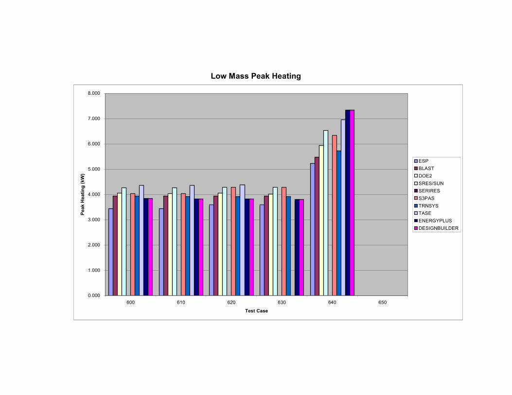
Low Mass Peak Heating
0.000
1.000
2.000
3.000
4.000
5.000
6.000
7.000
8.000
600 610 620 630 640 650
Test Case
Peak Heating (kW)
ESP
BLAST
DOE2
SRES/SUN
SERIRES
S3PAS
TRNSYS
TASE
ENERGYPLUS
DESIGNBUILDER

Low Mass Peak Cooling
0.000
1.000
2.000
3.000
4.000
5.000
6.000
7.000
8.000
600 610 620 630 640 650
Test Case
Peak Cooling (kW)
ESP
BLAST
DOE2
SRES/SUN
SERIRES
S3PAS
TRNSYS
TASE
ENERGYPLUS
DESIGNBUILDER

High Mass Annual Heating
0.000
1.000
2.000
3.000
4.000
5.000
6.000
900 910 920 930 940 950 960
Test Case
Annual Heating (MWhr)
ESP
BLAST
DOE2
SRES/SUN
SERIRES
S3PAS
TRNSYS
TASE
ENERGYPLUS
DESIGNBUILDER

High Mass Annual Cooling
0.000
0.500
1.000
1.500
2.000
2.500
3.000
3.500
4.000
900 910 920 930 940 950 960
Test Case
Annual Cooling
ESP
BLAST
DOE2
SRES/SUN
SERIRES
S3PAS
TRNSYS
TASE
ENERGYPLUS
DESIGNBUILDER
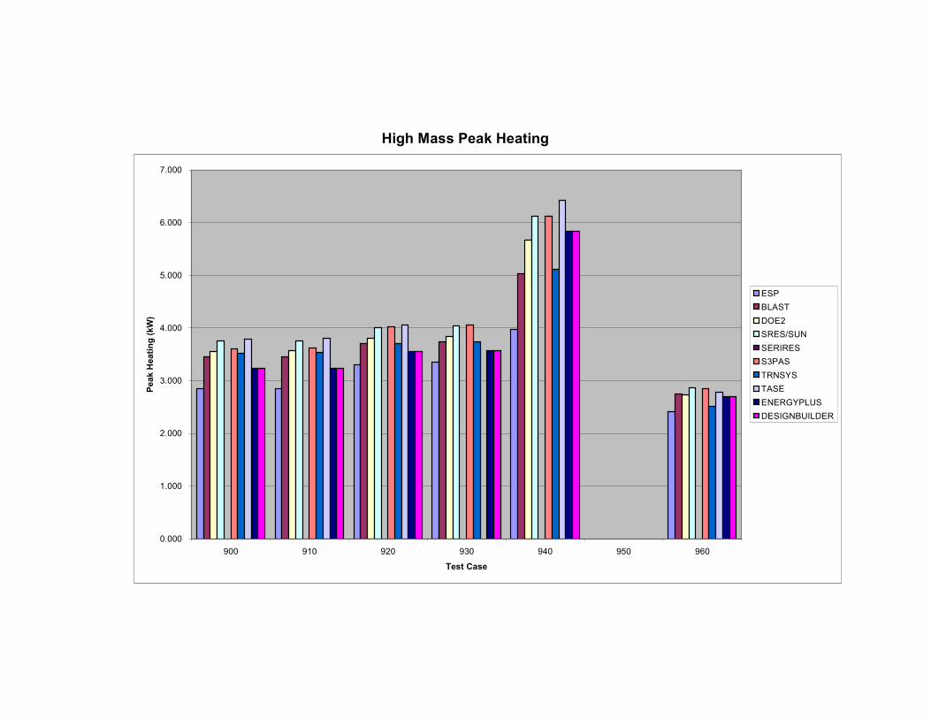
High Mass Peak Heating
0.000
1.000
2.000
3.000
4.000
5.000
6.000
7.000
900 910 920 930 940 950 960
Test Case
Peak Heating (kW)
ESP
BLAST
DOE2
SRES/SUN
SERIRES
S3PAS
TRNSYS
TASE
ENERGYPLUS
DESIGNBUILDER

High Mass Peak Cooling
0.000
0.500
1.000
1.500
2.000
2.500
3.000
3.500
4.000
4.500
900 910 920 930 940 950 960
Test Case
Peak Cooling (kW)
ESP
BLAST
DOE2
SRES/SUN
SERIRES
S3PAS
TRNSYS
TASE
ENERGYPLUS
DESIGNBUILDER

Appendix III
Free Floating Temperature Charts

Maximum Free Floating Temperature
0.000
10.000
20.000
30.000
40.000
50.000
60.000
70.000
80.000
600FF 900FF 650FF 950FF 960
Test Case
Maximum Temperature (C)
ESP
BLAST
DOE2
SRES/SUN
SERIRES
S3PAS
TRNSYS
TASE
ENERGYPLUS
DESIGNBUILDER

Minimum Free Floating Temperature
-25.000
-20.000
-15.000
-10.000
-5.000
0.000
5.000
10.000
600FF 900FF 650FF 950FF 960
Test Case
Minimum Temperature (C)
ESP
BLAST
DOE2
SRES/SUN
SERIRES
S3PAS
TRNSYS
TASE
ENERGYPLUS
DESIGNBUILDER

Average Free Floating Temperature
0.000
5.000
10.000
15.000
20.000
25.000
30.000
35.000
600FF 900FF 650FF 950FF 960
Test Case
Average Temperature (C)
ESP
BLAST
DOE2
SRES/SUN
SERIRES
S3PAS
TRNSYS
TASE
ENERGYPLUS
DESIGNBUILDER
Appendix IV
Sensitivity Comparison Charts

Low Mass Annual Heating (Sensitivity)
-2.500
-2.000
-1.500
-1.000
-0.500
0.000
0.500
1.000
610-600 620-600 630-620 640-600
Test Case
Difference (MWhr)
ESP
BLAST
DOE2
SRES/SUN
SERIRES
S3PAS
TRNSYS
TASE
ENERGYPLUS
DESIGNBUILDER

Low Mass Annual Cooling (Sensitivity)
-3.500
-3.000
-2.500
-2.000
-1.500
-1.000
-0.500
0.000
610-600 620-600 630-620 640-600 650-600
Test Case
Difference (MWhr)
ESP
BLAST
DOE2
SRES/SUN
SERIRES
S3PAS
TRNSYS
TASE
ENERGYPLUS
DESIGNBUILDER

Low Mass Peak Heating (Sensitivity)
-0.500
0.000
0.500
1.000
1.500
2.000
2.500
3.000
3.500
4.000
610-600 620-600 630-620 640-600
Test Case
Difference (kW)
ESP
BLAST
DOE2
SRES/SUN
SERIRES
S3PAS
TRNSYS
TASE
ENERGYPLUS
DESIGNBUILDER
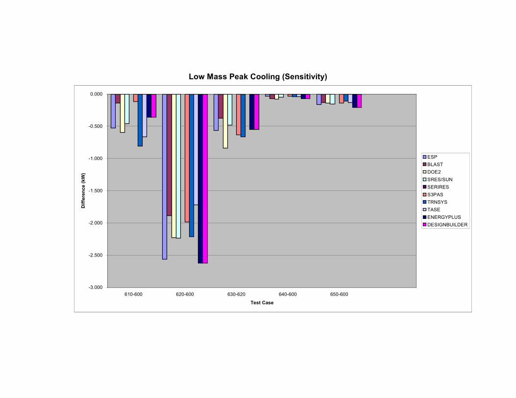
Low Mass Peak Cooling (Sensitivity)
-3.000
-2.500
-2.000
-1.500
-1.000
-0.500
0.000
610-600 620-600 630-620 640-600 650-600
Test Case
Difference (kW)
ESP
BLAST
DOE2
SRES/SUN
SERIRES
S3PAS
TRNSYS
TASE
ENERGYPLUS
DESIGNBUILDER

High Mass Annual Heating (Sensitivity)
0.000
1.000
2.000
3.000
4.000
5.000
6.000
900 910 920 930 940 950 960
Test Case
Difference (MWhr)
ESP
BLAST
DOE2
SRES/SUN
SERIRES
S3PAS
TRNSYS
TASE
ENERGYPLUS
DESIGNBUILDER

High Mass Annual Cooling (Sensitivity)
-5.000
-4.000
-3.000
-2.000
-1.000
0.000
1.000
900-600 910-900 920-900 930-920 940-900 950-900 960-900
Test Case
Difference (MWhr)
ESP
BLAST
DOE2
SRES/SUN
SERIRES
S3PAS
TRNSYS
TASE
ENERGYPLUS
DESIGNBUILDER

High Mass Peak Heating (Sensitivity)
-1.500
-1.000
-0.500
0.000
0.500
1.000
1.500
2.000
2.500
3.000
900-600 910-900 920-900 930-920 940-900 960-900
Test Case
Difference (kW)
ESP
BLAST
DOE2
SRES/SUN
SERIRES
S3PAS
TRNSYS
TASE
ENERGYPLUS
DESIGNBUILDER

High Mass Peak Cooling (Sensitivity)
-4.000
-3.500
-3.000
-2.500
-2.000
-1.500
-1.000
-0.500
0.000
0.500
900-600 910-900 920-900 930-920 940-900 950-900 960-900
Test Case
Difference (kW)
ESP
BLAST
DOE2
SRES/SUN
SERIRES
S3PAS
TRNSYS
TASE
ENERGYPLUS
DESIGNBUILDER

Appendix V
ANSI/ASHRAE Standard 140-2004 Output Form – Modelling Notes

STANDARD 140 OUTPUT FORM – MODELING NOTES
Software: DesignBuilder
Version: 1.2.0
Simulated Effect:
Inside and Outside convection algorithm
Optional Settings or Modelling Capabilities:
Inside convection algorithm: 1.Detailed
2. Simple
3. CIBSE
4. Ceiling diffuser
5. Glazed cavity
Outside convection algorithm: 1. Detailed
2. Simple
3. CIBSE
4. BLAST
5. TARP
6. DOE-2
7. MoWiTT
Setting or Capability Used:
Inside convection algorithm: 1.Detailed
Outside convection algorithm: 1.Detailed
Physical Meaning of Option Used:
The same detailed calculation method that was used for the GARD Analytics tests for
EnergyPlus are used to test DesignBuilder.
Simulated Effect:
Solar distribution effect
Optional Settings or Modelling Capabilities:
Solar distribution: 1. Minimal shadowing
2. Full exterior
3. Full interior and exterior
Setting or Capability Used:

Solar distribution: 3. Full interior and exterior
Physical Meaning of Option Used:
Full interior and exterior shadow calculations are performed each hour
Simulated Effect:
Various variables used to describe properties of surfaces
Optional Settings or Modelling Capabilities:
Thermal Absorptance: 0.0 to 1.0
Solar Absorptance: 0.0 to 1.0
Roughness: Very rough
Medium rough
Rough
Smooth
Medium smooth
Very smooth
Setting or Capability Used:
Thermal Absorptance: 0.9
Solar Absorptance: 0.6
Roughness: Rough
Physical Meaning of Option Used:
Thermal Absorptance: surface property describing ability to absorb incident
longwave radiation
Solar Absorptance: surface property describing ability to absorb incident solar
radiation
Roughness: surface roughness
Simulated Effect:
Simulation time increment
Optional Settings or Modelling Capabilities:
Number of time steps per hour=whole number between 1 and 60
Setting or Capability Used:
Number of time steps per hour=4

Physical Meaning of Option Used:
The simulation time increment is 15 minutes.
Simulated Effect:
Window properties for double pane glazing made of standard 3mm clear glass with
13mm air gap.
Optional Settings or Modelling Capabilities:
EnergyPlus requires window properties for front and back of window surface.
Setting or Capability Used:
Window properties were described as follows:
Thermal Properties
Property Value
Thickness 3.175 mm
Conductivity 1.060 W/mK
Solar Properties
Property Value
Solar transmittance 0.86156
Outside solar reflectance 0.07846
Inside solar reflectance 0.07846
Visible Properties
Property Value
Visible transmittance 0.91325
Outside visible reflectance 0.08200
Inside visible reflectance 0.08200
Infra-Red Properties
Property Value
Infra-red transmittance 0.00000
Outside infra-red reflectance 0.84000
Inside infra-red reflectance 0.84000
Physical Meaning of Option Used:

Description of window properties for double pane clear glass windows for
determining solar and conduction heat gain.
Simulated Effect:
Ground reflectance
Optional Settings or Modeling Capabilities:
Ground surface solar reflectance=0.0 to 1.0
Setting or Capability Used:
Ground surface solar reflectance=0.2
Physical Meaning of Option Used:
Property of the ground surface that describes the amount of incident solar radiation
that is reflected.