
Ansi a14.1 Ladders
81
By Authority Of THE UNITED STATES OF AMERICA Legally Binding Document By the Authority Vested By Part 5 of the United States Code § 552(a) and Part 1 of the Code of Regulations § 51 the attached document has been duly INCORPORATED BY REFERENCE and shall be considered legally binding upon all citizens and residents of the United States of America. HEED THIS NOTICE : Criminal penalties may apply for noncompliance. Official Incorporator: THE E XECUTIVE DIRECTOR OFFICE OF THE FEDERAL REGISTER WASHINGTON, D.C. Document Name: CFR Section(s): Date of Action: e ANSI A14.1-1990: Ladders--Wood--Safety Requirements 29 CFR 1917.119, 1918.24 74 FR 46358, Sept. 9, 2009
-
Upload
william-vang -
Category
Documents
-
view
236 -
download
0
Transcript of Ansi a14.1 Ladders

7/21/2019 Ansi a14.1 Ladders
http://slidepdf.com/reader/full/ansi-a141-ladders 1/81
By Authority Of THE UNITED STATES OF AMERICA
Legally Binding Document
By the Authority Vested By Part 5 of the United States Code § 552(a) and
Part 1 of the Code of Regulations § 51 the attached document has been dulyINCORPORATED BY REFERENCE and shall be considered legally
binding upon all citizens and residents of the United States of America.
HEED THIS NOTICE : Criminal penalties may apply for noncompliance.
Official Incorporator:
THE E XECUTIVE DIRECTOR
OFFICE OF THE FEDERAL REGISTER
WASHINGTON, D.C.
Document Name:
CFR Section(s):
Date of Action:
e
ANSI A14.1-1990: Ladders--Wood--Safety Requirements
29 CFR 1917.119, 1918.24
74 FR 46358, Sept. 9, 2009

7/21/2019 Ansi a14.1 Ladders
http://slidepdf.com/reader/full/ansi-a141-ladders 2/81
enz
eproduced By GLOB L
ENGINEERING DOCUMENTSWith The Pennission Of NSI
Under Royally ueemenl ANSI A14.1 1990
for laddersportable wood
safety requirements
..AIa lll-----------1III~ V ~ merican National Standards Institute
West42ndStreet
New York New York
10036

7/21/2019 Ansi a14.1 Ladders
http://slidepdf.com/reader/full/ansi-a141-ladders 3/81
7/21/2019 Ansi a14.1 Ladders
http://slidepdf.com/reader/full/ansi-a141-ladders 4/81
ANSI A14.1 - 1990
· merican National Standard
for ladde rs-portable w -
safety requirements
Approved by the A14 Committee during its
meeting 1 September 25 1992Admlnstratlve Co-Secretariat: American Society of Safety EngineersCo-Secretariat: American Ladder nstitute
The INTERPRETATION below represents the committee sview ofunderstanding properlythe use of abels/markings in the appendices of his staruiard
/Preface
Over the years there have been a number of interpretations
of various requirements within the A14 Ladder Standards.
One which keeps reappearing and has required periodic
revisiting is the LabelinglMarking requirements as theserelate to the illustrations of more detailed and apparently
specific labels markings in the appendix following
Appendix B To clarify this issue as defmitively as possible
the following interpretation, reviewed and approved by
the A14 Standards Committee, is provided:
Interpretation
While the requirements in the body of the Portable Ladder
Standards for labels/marking are keyed to specifically
numbered markings, the referred to labels/markings are
illustrations only and not intended to be exact renditions ofthe labels/markings placed on portable ladders. As
illustrations the labels/markings. except for technical
information in the text, are not required to be exact
duplications of those following Appendix B. The graphics
of the labels/markings including figures of users. arrows
out locations or direction, fonnatting text with the
1 f numbers or alphabet or both. and style of expression
not be followed exactly but rather is left to the
discretion of the developer of the label/marking or as
ordered by a label/marking buyer. Such text or verbiage
can be added to or presented more cogently as long as the
broad general intent of the label/marking is achieved
without changing the basic technical information thusmeeting the requirements of the standard for label/marking.
Underscoring the above position is the description of
labels/markings as illustrations. Use of the word illustration
has been specifically chosen, based upon its meaning,
which is defined as an example and explanation. Coupled
with this definition - and lending emphasis to it - is the
placement of the label/marking illustrations in the appendix
since appendices are not part of the standard but
explanations and elaborations of the standard and its
applicable requirements. In the traditional structuring anddevelopment of standards the use of the appendix was also
specifically chosen as a recognized means of stating
through illustration and explanation how requirements of
the standard can be implemented. The use of labels/
markings appendix and the illustrations contained therein
is construed in the broadest sense as offering designers or
buyers general guidance rather than dictating exact
duplication, in creating signs or labels/markings for portable
ladders.

7/21/2019 Ansi a14.1 Ladders
http://slidepdf.com/reader/full/ansi-a141-ladders 5/81
ERRATA SHEETAI4.1 • 1990)
9/19i91
FOREWORD - 2nd Page - 3rd Paragraph
Three 3) sentences are added to the end o he paragraph as follows:
While the effective date is 90 days from approval of the standard, actual determination is
based upon publication of the availability of the standard, which appeared in the August
10, 1991 issue o the ANSI Reporter. The aforementioned date would make November10, 1991 the effective date. However, inventories and stocks of labels/markings warrant
an additional 90 days for reasonable usage of existing stock.
FOREWORD - 2nd Page - 4th Paragraph
This paragraph becomes the 5th paragraph for the following new th paragraph:
An additional issue which has arisen is the requirement for the use of unwaxed vinyl tileas a testing surface. Recent experience and evidence indicate problems in the use of this
material which requires suspension o the use of these provisions in the standard. At arecent A14 Committee meeting 9119/91), the Committee appointed a task force to
research a more appropriate material.
PAGE 37 - Top Center of Page
Delete old Table 18 and replace with the following which corrects only the heading or
title o he test to Bottom Slip Test
Table 8
Bottom Slip Test
Test Weight on 3rd Horizonlal PullingHighest Fly Rung Force
Duty Rating and Type pounds) pounds)
Extra heavy duty· Type I
Heavy duty. Type I
Medium duty - Type n
Lightduty -Type ll
3
250
225
200
50
50
50
50

7/21/2019 Ansi a14.1 Ladders
http://slidepdf.com/reader/full/ansi-a141-ladders 6/81
) Administrative Co-Secretariat
American Society o Safety Engineers
Co-Secretariat
American Ladder Institute
Approved November 16. 1990
American National Standards Institute Inc
ANSI®
A14 11990
Revision t
ANSI A14.11982
American National Standard
or Ladders -
Portable Wood -
Safety Requirements

7/21/2019 Ansi a14.1 Ladders
http://slidepdf.com/reader/full/ansi-a141-ladders 7/81
merican
National
Standard
Published by
An American National Standard implies a consensus of those substantially concerned with its scope
and provisions. An American National Standard is intended as a guide to aid the manufacturer the
consumer and the general public The existence of an American National Standard does not in any
respect preclude anyone whether they have approved the standard or nOI from manufacturing.
marketing purchasing. or using products processes or procedures not confonning t the standard.
American National Standards are subject to periodic review and users are cautioned to obtain the
latest editions.
The American National Standards Institute does not develop standards and will in no circumstances
give an interpretation of any American National Standard. Moreover. no persons shall have the
right or authority to issue an interpretation ofan American National Standard in the name of the
American National Standards Institute.
CAUTION NOTICE: This American National Standard may be revised or withdrawn at any
lime. The procedures of the American National Standards Institute require that action be
taken to reaffirm revise or withdraw this standard no later than five years from the date of
publication. Purchasers of American National Standards may receive current information on
all standards by calling or writing the American National Standards Institute.
American Society of Safety Engineers
1800 East Oakton Street Des Plaines Illinois 60018·2187
Copyright 1990 by American National Standards Institute Inc.
All rights reserved.
No part of this publication may be reproduced
in any fonn in an electronic retrieval system or
otherwise. without the prior written pennissionof the publisher.
Primed in the United States of merica

7/21/2019 Ansi a14.1 Ladders
http://slidepdf.com/reader/full/ansi-a141-ladders 8/81
oreword (This Foreword is not a part of American National Standard AI4.1-1990.l
This standard is a revision of American National Standard Safety Requirements for Portable
Wood Ladders, ANSI A 14.1-1982. t is one of a series of five standards prepared under the
supervision of American National Standards Commictee on Safety in the Construction. Care.
and Use of Ladders, A 14 All five standards have been developed by subcommittees reponing
to American National Standards Committee A14 The subcommittees are: A 14-1. Ponable
Wood Ladders; A 14-2, Portable Metal Ladders; A 14-3, Fixed Ladders; A 14-4, Job-Made
Ladders; and A 14-5, Portable Reinforced Plastic Ladders.
All five standards, with the exception of A14·7 1990, Mobile Ladder Stands. derive from the
original American National Standard Safety Code for Construction, Care and Use of Ladders.
A14, which was first approved in 1923. Revisions were approved in 1935. 1948. and 1952.
The earl ier editions contained some treatment of metal and fixed ladders. Requirements for
these types of ladders were removed from the 1948 revision because rapid development in the
metal ladder field warranted special consideration and treatment of metal ladders and fixed
ladders (usually metal) in separate standards. In 1948, the code was revised and its title lind
designation changed to American National Standard ode for Wood Ladders. A 14.1. In 1952.
it was again revised and retitled American National Standard Safety Code for Portable Wood
Ladders. It was further revised in 1959, 1968, 1975, 1980, and 1982.
Responding to a Consumer Product Safety Commission challenge in August 1975. the A 14
Committee mounted a three-prong attack to upgrade the portable ladder standards within
the consensus framework of developing standards. Three Task Forces - Anthropometric.
Testing, and Labeling - were established in October 1975.
Without question the most massive and technically difficult task, which included a significant
amount of human-factors work, was carried out by the Testing Task Force. Over 100 known
ladder experts were solicited to join this task force and provide their tcchnicul expertise. The
work involved 50 meetings, over 400 test documents, and the use of numerous tcst ladders
over a period of nearly two years. The cost of the project has been conservatively estimuted al
over 300,000.
At the August I 1,1977, joint meeting of the Testing Task Force and the A 14 Advisory
Committee, 23 procedures were presented. These procedures, with an accompanying rationale
based upon statistical and human-factors data, were distributed l the three portable-ladder
subcommittees for review and incorporation into the standards. Recommendations for nomen
clature and for care and use of ladders, as well as the Ladder Use Survey Fonn and Bi-Level
Fall Victim Report Form that have been included in the Appendixes, had been previously
balloted in order that this more technical material from the Testing Task Force receive thefull attention of the three subcommittees.
Test procedures were developed for three different applications, namely, design verification,
quality control, and in-service testing. Design verification tests would generally be conducted
on a one-time basis during the original design development of the product and would usually
be destructive tests. Quality control tests would be conducted by the manufacturer on an
on-going basis; some of the tests would be destructive and some would be nondestructive.
In-service tests would be conducted by the user or a periodic basis and would be nondestructive in nature.
The A14 Committee adopted June 4, 1982*, as the effective date of ANSI A 14.1- 1981.
This was to allow the manufacturers the necessary lead time to evaluate their products for
confonnance to the 1981 edition of the three portable-ladder standards, to redesign and test
·The original effective date w s March 4, 1982.

7/21/2019 Ansi a14.1 Ladders
http://slidepdf.com/reader/full/ansi-a141-ladders 9/81
their products where applicable, to design and build the required manufacturing tooling and
machinery. and to convert their manufacturing operations to produce the revised products.
In 1981. experience by some of the manufacturers indicated that the inclined 10a J test was not
practical when applied a all available lengths of extension ladders. Also. recommendations
were received for clarifications in test procedure deSCriptions.
In the course of resolving these questions, evidence was produced to wamanty modifications
in the label test requirements. As a result. it became necessary to postpone the effective dateof these standards from 1une 4. 1982. to October 4. 1982. to allow investigations which
brought about needed changes in label test specifications.
In this current revision several issues which arose since the last revision are addressed. Most
notable is the label/marking section where improved graphics were developed as well as new
labels.
Suggestions for improvement of this standard will be welcomed. They should be sent to the
American Society o Safety Engineers, 1800 E. Oakton St.. Des Plaines. Ill. 60018.
The standard was processed and approved for submmittal to ANSI by American National
Standards Committee on Safety in the Construction, Care. and Use of Ladders. A14.
Committee approval o the standard does not necessarily imply that all the commitree
members voted for its approval. At the time it approved this standards. the A14 Committeehad the following members:
Lewis W. Berger, Chairman
Thomas F. Bresnahan. Secretary
Organization Represented Name o Representative
The Aluminum Association Robert I. Werner
Peter Pollak (Alt)
American Institute of Architects Robert H. Lee
American Insurance Association David P. Winger
Alliance of American Insurers Harry WinchellAmerican Ladder Institute Alan Kline
Robert I. Werner (AIt)
Associated General Contractors of America. Inc Vacant
Association of American Railroads T. M. Hatchard
Canadian Standards Association , . : . Robert Reid
Edison Electric Institute David C. Norman
Matthew Mingoia (Alt)Exchange Carriers Standards Association Robert A. Naser
Jonathan L. Shaw (Alt)
O. J. Gusella
Industrial Safety Equipment Association Allen Neustater
Frank E. Wilcher, Jr. (Alt)
International Brotherhood of Electrical Workers • Manuel A. MederosInternational Brotherhood o Painters Allied Trades George J. Jones
International Union of Bricklayers Allied Craftsmen Albert R. Couillard
Metal Ladder Manufacturers Association Richard L. Werner
Jerrold F. Hilton (Alt)Richard Sulecki (Alt)
Motor Vehicle Manufacturers Association , Michael Shust
Kenneth E. Lauck (Alt)

7/21/2019 Ansi a14.1 Ladders
http://slidepdf.com/reader/full/ansi-a141-ladders 10/81
National Association of Architectural Metal Manufacturers Philip B. Neilson
Robert 1 Lyons (Alt)
National Association of Government Labor Officials , .Kenneth J Zellar
John Molovich (Alt)
National Fire Protection Association Samuel C. Cramer
Ronald Bennett All)
National Retail Federation Joseph B. Siegel
Steel Plate Fabricators Association Ward Gill
Thunnond Yost (AIt)
Underwriters' Laboratories Edward Killoren
William R Hooper (Alt)
U S Consumer Product Safety Commission Colin B. Church*
los. Fandey (Alt)*
U.S. Dept. of Agriculture Vacant
U.S. Dept. of the Anny Corps of Engineers Jerry Haskins
U.S. Dept of Labor OSHA Terence Smith
Gilbert Esparza (Alt)
ANSI Z133.1 Committee Robert Felix
Independent Specialists Donald Bloswick
Subcommittee A14-1 on Portable Wood Ladders. which developed this
standard, had the following members:
Robert A Naser. Chamnan
*Nonvoting advisory member .
H W. Buschman
1 F Daly
R O Howland
E W Killoren
G.H.Kyanka
R F Nissly
1 L Shaw
H. W. Stillman. Jr.
C. R Wallick. Jr.
John E. Johnson
Harold W. Stillman, Jr.

7/21/2019 Ansi a14.1 Ladders
http://slidepdf.com/reader/full/ansi-a141-ladders 11/81
ontentsSECTION PAGE
I Scope and Purpose 9
1.1 Scope 9
1.2 Purpose . . . . . . . . . . . . . . . . . . . . . . . . . . . . . . . . . . . . . . . . . . . . . . . . . 9
2.General . . . . . . . . . . . . . . . . . . . . . . . . . . . . . . . . . . . . . . . . . . . . . . . . . . . . . . . 92.1 Rationale . . . . . . . . . . . . . . . . . . . . . . . . . . . . . . . . . . . . . . . . . . . . . . . . . 9
2.2 Application . . . . . . . . . . . . . . . . . . . . . . . . . . . . . . . . . . . . . . . . . . . . . . . 9
2.3 Interpretation . . . . . . . . . . . . . . . . . . . . . . . . . . . . . . . . . . . . . . . . . 9
2.4 Mandatory and Advisory Provisions 9
2.5 Equivalent 10
2.6 Effective Dale 10
3. Related Standards 10
4. Definitions and Nomenclature 10
5. Materials 12
5.1 Requirements for Wood Pans _ 12
5.2 Classification of Species of Wood 14
5.3 Hardware _ ' 14
5.4 Fasteners _ , 14
5.5 Alternate Materials _ _ 14
6. Construction Requirements 14
6.1 Basis of Requirements J4
6.2 Portable Stepladders 15
6.3 Portable Rung Ladders 22
6.4 Special-Purpose Ladders 27
6.5 Step Stools (Ladder Type) 28
7. Design Verification Test Requirements 29
7.1 General 29
7.2 Tests For Single and Extension Ladders
7.2.1 Simulated In-Use Inclined Load Test 30
7.2.2 Hardware Test Requirements for x t ~ n s i o n Ladders 30
7.2.3 Side-Rail Cantilever Dynamic Drop Test for Single and
Extension Ladders 34
7.2.4 Ladder Section Twist Test for Single and Extension Ladders 34
7.2.5 Bottom Slip Test 37
7.2.6 Multisection Extending Force Test for Extension Ladders 37
7.3 Tests for Stepladders, Platform Ladders, Trestle Ladders,
Extension Trestle Ladders. and Step Stools 37
7.3.1 Compression Test 37
7.3.2 Bucket Shelf Test for Stepladders 37
7.3.3 Front Stability Test for Stepladders, Platform Ladders,
Trestle Ladders, Extension Trestle Ladders, and Step Stools 37
7.3.4 Side Stability Test for Stepladders. Platform Ladders,
Trestle Ladders, Extension Trestle Ladders. and Step Stools 40
7.3.5 Rear Stability Test for Stepladders. Platform Ladders,
Trestle Ladders, Extension Trestle Ladders, and Step Stools 40

7/21/2019 Ansi a14.1 Ladders
http://slidepdf.com/reader/full/ansi-a141-ladders 12/81
I
'-.J
)
SEcnON PAGE
7.3.6 Torsional Stability Test for Stepladders, Platform Ladders,
Trestle Ladders, Extension Trestle Ladders, and Step Stools 40
7.3.7 Racking Test for Stepladders, Platfonn Ladders, Trestle Ladders,
Extension Trestle Ladders 44
7.3.8 Front Rail and Back Leg Dynamic Drop Test for Stepladders,
Platform Ladders, Trestle Ladders, Extension Trestle Ladders,and Step Stools 44
7.3.9 Rail Torsion and Spreader Test for Stepladders, Platform
Ladders, Trestle Ladders, and Extension Trestle Ladders
7.3.10 Stepladder Slip Test 44
7.4 Labeling Tests 5
8. Selection, Care, and Use 46
8.1 ~ n e r l 46
8.2 Selection 46
8.3 Rules for Ladder Use 48
8.4 Care • • • 50
9. Labeling/Markiog Requirements 1
9 1 Primary Hazard Danger and Caution Markings 19.2 Product Data Information Markings 52
10. Revision of American National Standards Referred to in This Document 53
Tables
Table 1 Classification of Various Species of Wood Acceptable for
Use in Ladders 16
Table 2 Minimum Dimensions for Type-I and -IA Stepladders 19
Table 3 Minimum Dimensions for Type-ll Stepladders 20
Table 4 Minimum Dimensions for Type-Ill Stepladders 1
Table 5 Minimum Dimensions of Side Rails for Single Ladders 23
Table 6 Minimum Dimensions of Side Rails for Two-Section
Extension Ladders • 24
Table 7 Minimum Overlap for Two-Section Extension Ladders 25
Table 8 Minimum Distance between Points of Bearing for Two-Section
Extension Ladders : 25
Table 9 Guide Iron Dimensions for Extension Ladders 25
Table 10 Minimum Dimensions of Side Rails for Sectional Ladders 26
Table 11 Minimum Dimensions of Side Rails for Trestle Ladders or Base
Sections of Extension Trestle Ladders 27
Table 12 Minimum Dimensions of Side Rails for Extension Sections of
Extension Trestle Ladders 27
Table l3 Required Extension Trestle Ladder Overlap 27
Table 14 Minimum Dimensions of Side Rails and Rungs for Masons Ladders 28
Table 15 Single and Extension-Ladder Inclined Load Test 30
Table 16 Hardware Tests • 32
Table 17 Ladder Section Twist Test 36
Table 18 Bottom Slip Test 37
Table 19 Stabili ty Test Loads 39
Table 20 Maximum Allowable Racking Deflection 43
Table 21 Rail Torsion Test 44
Table 22 Summary of Significant Accident Causes .47
Table 23 Ladder Size, Working Length, and Height 48

7/21/2019 Ansi a14.1 Ladders
http://slidepdf.com/reader/full/ansi-a141-ladders 13/81
SECTION
Figures
Fig 1
Fig 2Fig 3Fig. 4
Fig. 5Fig. 6Fig 7
Fig 8Fig 9
Fig. t
Fig.
Fig. 12
Fig l3
Fig. 4Fig. 15
Appendixes
PAGE
Inclined Load Test 30
Cyclic Rung Lock Test Arrangement 31
Rung Lock Testing Cycle 32
Single Lock Load Test 33
Standard Loading Block 33Lock Tip Load Test 34
Side-Rail Cantilever Dynamic Drop Test 35
Single or Extension-Ladder Twist Test 35
Bottom Slip Test 36
Compression Test 38
Front, Side, and Rear Stability Test 39
Torsional Stability and Rail Torsion and Spreader Tests 41
Racking Test 42
DynamiC Drop Test 43
Stepladder Slip Test 45
Appendix A Fonnato
Design and Color for Primary Hazard Dangerand Caution Labels/Markings 54
Appendix B Fonnat o Design and Color for the Safety First and
Notice Labels/Markings 55
Markings
Marking No 00 - All Ladders , , , 56
Marking No I, 2 and 3 - Step Ladders 57
Marking No.4 - Step Ladders 58Marking No.5, 6 and 7 - Extension Ladders 58
Marking No.8 and 9 - Extension Ladders 59
Marking No 10 - Extension Ladders 60
Marking No 11 and 12 - Step Stools 60
Marking No 13 - Trestle Ladders 61
Marking No 14 - Extension Trestle Ladders 61
Marking No 15 - Platform Ladders , 62
Marking No 16 - All Ladders 62
Appendix C Data Gathering Fonns 63

7/21/2019 Ansi a14.1 Ladders
http://slidepdf.com/reader/full/ansi-a141-ladders 14/81
)
)
)
merican National Standard
for Ladders
Portable Wood
Safety Requirements
1 Scope and Purpose
1.1 Scope. This standard prescribes rules and estab
lished minimum requirements for the construction,
testing, care, and use of the common types of portable
wood ladders described herein in order to ensure
safety under nonnal conditions of usage. It does not
cover step stools (furniture type), except ladder-type
step stools (see 6.4.4 for other exceptions), nor does it
cover ladder accessories, including, but not limited to.
ladder shoes, ladder levelers, ladder stabilizers or
stand-off devices, ladder jacks, or ladder straps and
hooks, that may be installed on or used in conjunction
with ladders.
These requirements are also intended to prescribe
rules and minimum criteria for labeling/marking of
the kinds of portable ladders cited in this standard but
exclusive of furniture type step stools and special
purpose ladders. These labeling/marking requirements
do not apply to those situations where user's training,
supervision, or documented safety procedures would
duplicate, exceed or be in conflict with the label
ing/marking requirements.
1 2 Purpose. The purpose of this standard is to pro
vide reasonable safety for life. limb. and property. In
order to develop an effective safety program, the
standard should also serve as a basis for purchase re
quirements and for instruction in personnel training
and in the preparation of motivational/instructional
material, such as safety practices, manuals, posters,
and the like. This standard is also intended to provide
the manufacturer. purchaser. and user of wood ladders
with a set of specifications and requirements against
which a ladder may be compared.
It is not the purpose of this standard to specify all
the details of construction of portable wood ladders.
The limitations imposed are for the purpose of provid
ing adequate general requirements and testing methods
needed for consistency.
AMERICAN NA1l NAL STANDARD A 14.1 1990
2 Genera)
2.1 Rationale. A rationale has been developed
covering the specifications and performance require
ments of this standard. I
2.2 Application. his standard is intended for
voluntary use by establishments that use or manufac
ture ladders. It is also designed to serve as a guide to
federal and state authorities or other regulatory bodies
in the formulation of laws or regulations.
The methods employed to ensure compliance with
this standard shall be determined by the proper
regulatory or administrative authority.
2.3 Interpretation. To secure uniform application
of this standard. it is recommended that sugge ;tions
involving changes in the requirements or disputes
over their interpretation be referred to the following
organization:
American Society of Safety Engineers, 1800 E
Oakton SI., Des Plaines, Ill. 60018
In view of the different kinds of ladders and the
many different conditions under which they are used,
this standard should be liberally construed. In cases of
practical difficulty or under special-service conditions,
it is expected that the administrative authority will
grant exceptions to the literal requirements of this
standard or will permit the use of alternative designs
or features, but only if equivalent safety is thereby
secured.
2.4 Mandatory and Advisory Provisions. The
world "shall" is to be understood as denoting a
mandatory requirement. The word "should" is to
be understood as denoting a recommendation.
'Thc ralionaJe is on file with Ihe co-sccrelarial.
9

7/21/2019 Ansi a14.1 Ladders
http://slidepdf.com/reader/full/ansi-a141-ladders 15/81
AMERICAN NA11 NALSTANDARD AI4.1-1990
2 S Equivalent. The word equivalent in this
standard means a construction. connection, Or material
providing equal perfonnance.
2 6 Effective Date. The requirements of this stand
ard shall become effective 90 days after the revised
A14 1 standard is approved by ANSI
3 Related Standards
This standard is intended for use in conjunction with
the following American National Standards or latest
revision (See section 10):
American National Standard Safety Requirements for
Scaffolding, ANSI AIO.8-1988
American National Standard for Ladders - Portable
Metal - Safety Requirements, ANSI A 14.2·1990
American National Standard for Ladders - POJ1ableReinforced P I ~ s t i c - Safety Requirements, ANSI
A 14.5-1982
American National Standard Nomenclature of Domes
tic Hardwoods and Softwoods, ANSI/ASTM Dl165-80
American National Standard Methods for Establishing
Clear-Wood Strength Values, ANSIIASTM D2555-88
4 Definitions and Nomenclature
angle of inclination. The preferred pitch for portable
non-self-supporting ladders.
back leg rear rail). The support members of a self
supporting portable ladder back section. The back legs
are joined by rungs, bars, rear braces, or other bracing
to fonn the back section.
combination ladder. A portable ladder capableof
being used either as a stepladder or as a single or
extension ladder. It may also be capable of being used
as a trestle ladder or a stairwell ladder. Its components
may be used as single ladders.
double front ladder. A self-supporting portable
ladder. non-adjustable in length with flat steps frontand back that can be climbed on either side by oneperson at a time.
duty rating. The combination of factors, including,but not limited tO,ladder type and design features
which imply service capability.
IAn optional a ~ c e s s o r y
10
extension ladder. A non-self-supporting portable
ladder, adjustable in length. It consists of two or
more sections traveling in guides or brackets or the
equivalent and so arranged as to pennit length
adjustment.
extension trestle ladder. A self-supporting portable
ladder, adjustable in length, consisting of a trestle ladder base and a venically adjustable extension section
with a suitable means for locking the ladders together.
highest standing level. The vertical distance.
expressed in feet and inches, from the uppennost
step or rung the climber is advised to use to the
horizontal plane of the ladder base support, with the
portable ladder in the preferred climbing position.
inside clear width. The distance between the inside
flanges of the siderails of a ladder.
ladder. A device incorporating or employing steps
or rungs on which a person may step to ascend ordescend.
ladder foot, shoe', or skid-resistant bearing surface_
That component of ladder support that is in contact
with the lower supporting surface.
ladder type. The designation that identifies theworking load.
marking. Any sign. label, stencil, or plate of a primary
hazard or infonnational character, or both, affixed,
painted, burned, stamped, or embossed on the ladder
surface. (For examples, see Appendixes A and B.
maximum extended length or maximum working
length. he total length of the extension ladder when
the middle or intennediate and top or fly sections are
fully extended (maintaining the required overlap).
nail. A steel nail, unless otherwise designated.
permanent deformation (set). That defonnation
remaining in any part of a ladder after all loads have
been removed.
pitch. The included (acute) angle between the horizon
tal and the ladder, which is measured on the side of
the ladder opposite the climbing side. It is usually
expressed as the ratio HIL which is the horizontal
distance from the base of the ladder to the support
ing surface divided by the working length L of the
ladder.
platform. A landing surface that is used as a working
or standing location.

7/21/2019 Ansi a14.1 Ladders
http://slidepdf.com/reader/full/ansi-a141-ladders 16/81
)
platform ladder. A self-supporting portable ladder
of fixed size with a platfonn provided at the intended
highest standing level.
portable ladder. A ladder that can readily be moved
or carried, usually consisting of side rails joined at
intervals by steps. rungs. or rear braces.
rail . The side members joined at intervals by either
rungs or steps.
rear braces. Crosspieces or diagonals in the back
section of a self-supporting ladder) not intended for
climbing. which may be spaced at any interval.
rungs or steps. Ladder crosspieces that are intended
for use by a person in ascending or descending.
scaffold. A temporary elevated platform and its sup
poning structure used for supporting worker s) or
materials or both.
section
1) bottom or base section. The lowest section of
a non-self-supporting portable ladder.
2) top or ny section. The uppermost section of a
non-self-supporting portable ladder.
3) middle or intermediate section. The section
between the top fly) and bottom base) sections of a
non-self supporting portable ladder.
secHonalladder. A non-self-supporting portable
ladder, nonadjustable in length, consisting of two or
more sections, so constructed that the sections may
be combined to function as a single ladder.
single ladder. A non-self-supporting portable ladder,
nonadjustable in length, consisting of one section.
size. The quantitative description of the length of the
ladder. Methods of defining size are presented in the
individual standards.
special-purpose ladder. A portable ladder that is
either an experimentally designed ladder or a modifi
cation or assemblance of A14 approved requirements
for design.
stand-off. A means by which a ladder may be erected
at some horizontal distance away from its upper .support point.
stepladder. A self-supporting portable ladder. non
adjustable in length, with flat steps and a hinged back.
step stool ladder type). A self-supporting, foldable,
portable ladder. nonadjustable in length, 32 inches or
less in overall size, with flat steps and without a pail
AMERICAN NATIONAL STANDARD A14.1 1990
shelf. designed so that the ladder top cap as well as all
steps can be climbed on. The side rails may conlinue
above the top cap.
step sur faces. The clear portion of steps or rungs on
which a person may step while ascending or descend·
ing a ladder.
test failure. Damage or visible weakening of the
ladder structure or a component, except where other
wise defined by the leSI protocol.
test load. The applied load used to demonstrate
compliance with a perfonnance test requirement.
top cap. The uppermost horizontal member of a
portable stepladder.
top step. The first step below the top cap of a portable
stepladder. Where a ladder is constructed without a top
cap, the top step is the first step below the top of the
rails.
trestle ladder. A self-supporting portable ladder,
non-adjustable in length. consist ing of two sections
intended for climbing on both sides simultaneously.
with rungs or bars for climbing, hinged at the top to
form angles with the base.
ultimate failure. The collapse of the ladder structure
or, where applicable, a component thereof.
unwaxed vinyl tile. In Ihis standard shall be Ihe
Official Yinyl Composilion Tile OYCT) available
from the Chemical Specialties Manufacturers Association, 1001 Connecticut Ave • Washington, DC 20036.
visual damage. Damage evident by visual inspection.
visual inspection. Inspection by the eye without
recourse to any optical devices except prescription
eyeglasses.
wood characteristics. Distinguishing features, the
extent and number of which detennine the quality of
a piece of wood.
wood irregulari ties. Natural characteristics in or on
the wood that may lower its durability, strenglh, or
utility.
I) bark pocket. n opening between annual
growth rings that contain bark. Bark pockets appear as
dark streaks on radial surfaces and as rounded areas on
. tangential surfaces.
2) check. A separation of the wood along the fiber
direction that usually extends across the rings of
11

7/21/2019 Ansi a14.1 Ladders
http://slidepdf.com/reader/full/ansi-a141-ladders 17/81
AMERICAN NATIONAL STANDARD AI4.1·1990
aMual growth, commonly resulting from stresses set
up in the wood during seasoning.
(3) compression failure. A defonnation (buckling)
of the fibers due to excessive compression along the
grain. This deformation may appear as a wrinkle
across the surface. In some cases, compression failures
may be present but not visible as wrinkles; in such
cases they are often indicated by fiber breakage on
end grain surfaces.
(4) compression wood. An aberrant (abnonna\)
and highly variable type of wood structure occurring
in softwood species.(5) cross grain (slope of grain). A deviation of the
fiber dire tion from a line parallel to the sides of the
piece. Cross grain may be-diagonal or spiral. or both.
6) decay. The disintegration of wood due to the
action of wood-destroying fungi; also known as dote
and rot.(7) knot. A portion of a branch or limb, embedded
in the tree and cut through in the process of lumbermanufacture. It is classified according to size. quality,
occurrence, and location in the cross section of a piece.
The size of the knot is determined by its average
diameter on the surface of the piece.
8) low-density wood. Wood that is exceptionally
light in weight and usually deficient in strength proper
ties for the species. In softwood species. low density
frequently indicated by exceptionally wide. or
sometimes by extremely narrow. rings. and generally
a low proportion of latewood. On the other hand.
low.density hardwood. at least in ring·porous species.
is mOSl commonly indicated by excessively narrow
annual rings in which the earlywood portionpredominates.
9) pitch pocket. An opening extending parallel
10 the annual growth rings that contains. or that has
contained. either solid or liquid pitch.
10 shake. A separation along the grain. occurring
most often between the rings of annual growth.
r I ) split. A separation of the wood parallel to the
fiber direction due to tearing apart of the wood fibers.
normally caused by extemal forces.
( 12) wane. Bark. or lack of wood. on the comer of
a piece.
working length. The length of a non-self-supportingportable ladder measured along the rails from the base
support point of the ladder to the point of bearing at
the lap.
working load. The maximum applied load, including
the weight of the user. materials, and tools, which the
ladder is to support for the intended use.
12
5. Materials
5 1 Requirements for Wood Parts
5.1.1 Requirements Applicable to All Wood
Parts
5.1.1.1 General Requirements. All wood
parts of the species specified in Table 1 shall be
seasoned at the time of manufacture to a moisturecontent of not more than 15 percent; smoothly
machined and dressed on all sides; free from sharp
edges and splinters; and sound and free by accepted
procedures of visual inspection from shake. wane,
compression failures, decay, or other irregularities
except as hereinafter provided. Low·density wood
shall not be used.
To allow for normal variations in width and
thickness which occur in surfacing lumber. on up
to 5 percent of the length of a part, the depth and
thickness may be undersized a maximum of 1/64
when measl,lred at a moisture content of 15 percent.
Permissible irregularities as provided for in this
standard are based on minimum dimensions. When
oversized pans are used some deviations from those
irregularities may be allowable.
5.1.1.2 Compression Wood. Compression
wood is found mostly in softwoods. Compression
wood commonly hasu density somewhat higher than
that of nonnal wood but have somewhat lower stiff·
ness and tensile strength for their weight. Compression
wood hus high longitudinal shrinkage thut frequently
causes warping of long, slender structural members
such as ladder rails. This variant type of wood struc-
ture. when of a damaging nature, can be readily
identified. by competent and conscientious visual
examination, by its relatively wide annual rings and
large proportion of late wood, which is yellow in color
and commonly has a dull lifeless appearance. More·
over. the yellow latewood merges with earlywood of
the same annual rings rather than being more sharply
delineated as in many softwood species. The extent of
compression wood's effects on strength and warping
varies with the proportion of compression wood in a
cross section. For example, wide streaks of readily
identifiable compression wood comprising the larger
part of the annual rings in a piece of lumber are as-
sociated with more seriously adverse properties thannarrow streaks involving only a few annual rings,
particularly when the latewood comprises one-third
or less of the ring widths in narrow streaks.
5.1.1.3 Cross Grain. Cross grain is limited in
terms of its slope, which is defined as the distance
along the sides of the piece in which a deviation of the
grain of I inch occurs. For example, cross grain with a

7/21/2019 Ansi a14.1 Ladders
http://slidepdf.com/reader/full/ansi-a141-ladders 18/81
slope of 1 in 12 means that in a distance of 12 inches
the grain deviates 1 inch from the edge of the piece.
The slope of grain shall be measured over a distance
that will ensure that the determinat ion of the general
sloper of the grain is not influence by short local
deviations.
Location deviations of the grain from the generalslope in the piece are usually associated with a knot
or other irregularity that mayor may not be present in
the piece. In addition to the limits on general slope
of grain it is also desirable in pieces of small cross
section such as occur in ladder parts to limit the
occurrence of local deviations except for those which
are associated with otherwise permitted irregularities
appearing in the piece.
5.1.1.4 Limited Irregularities Black streaks
in western hemlock shall not be considered an
irregUlarity. However chambers associated with
black streaks when present in the part shall be
limited as specified for pitch and bark pockets.
5.1.2 Permissible Irregularities in Side Rails
and Back Legs
5.1.2.1 Cross Grain The general slope of the
grain in side rails and back legs shall not be steeper
than 1 in 12 except for ladders under 10 feet in length
and having flat steps for treads in which the general
slope of the grain shall not be steeper than 1 in 10. The
slope of the grain in areas of local grain deviation shall
be limited as above when occurring on the narrow face
or in the outer one-fourth of the width of the wide
face. Local areas of grain deviation within the center
half of the width of the wide face may be pennitted to
contain a grain slope as steep as 1 in 8. Local devia
tions of grain associated with otherwise pennissible
irregularities shall be pennitted .
5.1.2.2 Knots. Knots shall not appear in a
narrow face of a side rail or back leg. Knots if tight
and sound and less than 1/2 inch in diameter shall be
permitted on the wide face provided no part of the
knot is within 1/2 inch from either edge and knots are
not more frequent than one in any three feet of length.
5.1.2.3 Pitch and Bark Pockets Pitch and
bark pockets in side rails and back legs shall be
pennitted provided that there is not more than onethat is 1/8 inch in width. 2 inches in length and 1/2
inch in depth. or the equivalent of smaller pockets
on the b ~ s i s of exposed area and depth per each 3 feet
of length.
5.1.2.4 Checks. Checks that are not more
~ h n 6 inches in length or 1/2 inches in depth shall be
pennitted in side rails or back legs.
AMERICAN NATIONAL STANDARD A 14.1·1990
5.1.2.5 Splits. Splits that are not more than 2
inches in length shall be penniued in side rails and
back legs.
5.1.2.6 Compression Wood Occurrences of
compression wood in relatively small amounts and
positively identified by competent and conscienlious
visual inspection of side rails and back legs shall be
pennined provided that no single streak exceeds 1/2
inch in width and that the aggregate of streaks does nol
exceed in width one-fourth of the wide face of the side
rail. No streak of compression wood shall be allowed
on the narrow face of the rail. Borderline fonns of
compression wood not positively identified by com
petent and conscientious visual inspection shall be
pennined. Those pans containing bow or crook that
would interfere with the operation of the ladder shall
not be used. No streaks of compres sion wood shall be
within 1/2 inch of the edge of the rail.
5.1.3 Permissible Irregularities in Flat Steps
Rungs and Other Ladder Parts5.1.3.1 Cross Grain in Parts Other Than
Rungs. The general slope of grain shall not be steeper
than I in 12 in pieces for ladders 10 feet and greater
in length and not steeper than I in lOin pieces for
ladders less than 10 feet in length. The slope of the
grain in areas of local deviation shall be limited as is
the general slope of the grain. For all ladders. cross
grain not steeper than 1 in 1 may be pennitted in lieu
of 1 in 12 provided the size of the part is increased 10
afford at least 15 percent greater calculated strength
than in ladders built to minimum dimensions. Local
deviations of grain associated with otherwise per
missible irregularities shall be permitted.5.1.3.2 Cross Grain in Rungs The general
slope of the grain and the slope in areas of local. devia
tion shall not be steeper than 1 in 15. For all ladders.
cross grain not steeper than 1 in 12 may be permitted
in lieu of I in 15 provided the size of the part is
increased to afford at least 15 percent greater
calculated strength than in ladders built to minimum
dimensions. Local deviations of grain associated with
otherwise permissible irregUlarities shall be permitted.
5 1 3 3 Knots. Permissible knots shall be
sound and tight. Knots over 1/8 inch in diameter shall
not appear in rungs. Knots shall not appear in the
narrow faces of flat steps. Knots appearing in the
wide faces of flat steps shall not exceed 1/4 inch in
diameter. Knots in other ladder pans shall comply
with the requirements of 5.1.2.2.
5.1.3.4 Pitch and Bark Pockets Pitch and
bark pockets shall be pennitted provided that there is
nol more than one that is 1/8 inch in width 2 inches in
length. and 1/2 inch in depth or the equivalent of
13

7/21/2019 Ansi a14.1 Ladders
http://slidepdf.com/reader/full/ansi-a141-ladders 19/81
AMERICANNA110NAL STANDARDAI4.1·1990
smaller pockets on the basis of exposed area and
depth, per each 3 feet of length.
5.1.3.5 Checks. Seasoning checks shall be
pennitted at the time of manufacture provided that
the checks are not more than 6 inches in length or
1/2 inch in depth.
5.1.3.6 Splits. Splits shall be permitted at timeof manufacture provided that they are not more than 2inches in length.
5.1.3.7 Compression Wood. Occurrences of
compression wood, positively identified by competent
and conscientious visual inspection, shall be pennitted
provided that no single streak exceeds 1/2 inch in
width and that the aggregate of streaks does not
exceed in width one-fourth of the wide face. No streak
of compression wood shall be allowed on the narrow
face. Borderline fonns of compression wood not posi·
tively identified by competent nd conscientious visual
inspection shall be permitted. Parts containing bow or
crook that would interfere with the operation of theladder shall not be used.
5.2 Classification of Species of Wood. Table I gives
a list of native woods, divided into five groups on the
basis of their mechanical properties, considered from
the viewpoint of use for ladder construction.
5.2.1 Side Rails nd Flat Steps. All minimumdimensions and specification set forth hereinafter for
side rails and flat steps shall be followed, except that
wood from species of group E may be substituted for
wood from group D when the former is used in sizes
that provide equivalent strength. (See Note 6 of Table
I for suggested methods of size adjustment.)5.2.2 Rungs. All m n mum dimensions and
specifications set forth hereinafter for rungs are based
on the species of wood listed in group Aof Table I
5.3 Hardware. Hardware shall be made of
aluminum. steel, wrought iron, malleable iron, or other
material that is adequate in strength for the purpose
intended and free from sharp edges and from sharp
projections in excess of 1/64 inch. The materials shall
be corrosion and weather resistant.
5.4 Fasteners. Fasteners shall be applied in a tight
and secure manner and remain so with nonnal use and
care, or be such that they can be field tightened. Rivets
shall be peened or set over the hardware or a washer.
The washers shall be standard riveting bUlTs; that is,
3/16 inch diameter rivets shall use a minimum 1(2 inch
diameter bUIT, and 1/4 inch diameter rivets shall use a
minimum 5/8inch diameter burr. The head of the rivet,
when used against wood, shall be a wagon box, truss,
or similar type head to afford adequate bearing against
14
the wood. Holes drilled in wood parts for fasteners
shall not exceed the diameter of the fastener by more
than 1/32 inch.
5.5 Alternate Materials. When a wood ladder is
manufactured with a part or parts made of some other
material aluminum or steel steps, top cap, or rungs),
or species not herein specified, these parts shan meetthe requirements of this and other applicable American
National Standards for ladders. A component part
made of other wood-base material may be substituted
if it has strength, stiffness, durability, perfonnance,
and weathering characteristics at least equal to or
exceeding the solid lumber component specified in
this standard.
6. Construction Requirements
6.1 Basis of Requirements
6.1.1 Types of Ladders6.1.1.1 Type IA. Type IA is an extra-heavy
duty industrial ladder with a 300·pound duty rating.
These ladders are for frequent extra·heavy-duty
applications, such as industry, utilities, contractors,
and the like.
6.1.1.2 Type I. Type I is a heavy-duty in·
dustrialladder with a 250-pound duty rating. Theseladders are for applications such as industry, uti lilies,
contractors, and the like.
6.1.1.3 Type IL Type Il is a medium-duty
commercial ladder with a 225-pound duty rating. It
is for applications such as offices, light maintenance,
and the like.
6 1 1 4 Type III. Type III is a light-duty
household ladder with a 200·pound duty rating:
These ladders are for light household use.
6.1.2 General. The dimensions specified here·
inafter for wood ladders are the minimum dressed
cross·sectional dimensions for the types of ladders
herein designated, based on the species of wood
specified in 5.2, at a moisture content of 15 percent.
The dimensions for side rails are based on a mortise or
gain as specified herein for the various types of ladders
for step or rung attachments. Where the strength of the
side rails or back legs is reduced by a greater mortise
or gain than specified, or where it is desired to use for
any wood part a cross section either dimension of
which is less than specified, the required dimensions
may be found as indicated in 6.1.3.
6.1.3 Formula for Determining Dimensions
6.1.3.1 For the side rails of single, extension,
and sectional ladders, the proposed section shall
develop an actual stress per square inch not greater

7/21/2019 Ansi a14.1 Ladders
http://slidepdf.com/reader/full/ansi-a141-ladders 20/81
than 2000 pounds for group A and B woods, 1875
pounds for group C woods, 1600 for group D woods,
or 1375 pounds for group E woods when computed by
the following fonnula applying to rectangular sections,
with a maximum tolerance of 5 percent over these
stresses:
1 5 W P +W/16)
Eq. I)B D3 -O.67)
where
P =one-eighth of the duty rating, which is the nor
mal component of the applied load to each rail
at the center of the ladder, when the foot of
the ladder is moved out of the perpendicular
by one-quarter of its length. P is 37.5 pounds
for type lAo 31.25 pounds for type I, 28.125
pounds for type II and 25 pounds for type III
fb =stress in extreme fiber in pounds per square
inch
W =weight of ladder in pounds see first footnoteofTable 1)
L = maximum working length ofladder in inches
size of ladder less minimum overlap for two
section extension ladder, less 12 inches or 6-
inch overhang at each support point)
B = net thickness of each side rail in inches
D =depth of side rail in inches
d =diameter of hole bored for rung t;P shall be
taken as not less than 0.67; this adjustment is
for loss of strength in rail from boring of rung
hole of7/8-inch diameter)
Equation I is a simplified fonnula for determiningrail sizes.
6.1.3.2 Adjustment of sizes for wood parts of
stepladders and other ladder types covered in this
standard may be made as follows:
I) The dimensions throughout this standard for
parts having rectangular cross sections generally repre
sent only one of a number of possible combinations of
thickness and width that could satisfy the requirements
for strength and stiffness. Depending upon the material
sizes available, manufacturing practices, and other
such variable factors. parts produced by a particular
manufacturer mayor may not agree exactly with the
sizes given subsequently. The rest of 6.1.3.2 providesmeans for determining equality of load-carrying
capacity of parts of different sizes, or for determining
the sizes needed to provide equality.
2) Any changes in dimensions made in accordance
with 6.1.3.2 3) shall result in a change in the width
thickness ratio for side rails or back legs not greater
than 25 percent from the ratio now specified in this
AMERICAN NATIONAL STANDARD AI4.1-1990
standard for a corresponding ladder unless new dimen
sions provide a cross section that has a greater
modulus or equivalent strength and safety).
3) Where both dimensions re different from those
specified. the load-carrying capacity in bending of a
part will be equal to or greater than that of a part of
specified dimensions if the changed section modulus
equals or exceeds the specified one: that is:
Eq.2)
where
B= imension of the part at right angles to the
direction of load width of a step. thick
ness of a side rail or back leg)
D = imension of the part parallel to the direc
tion of load thickness of a step. w i t ~ of
a side rail or back leg)
B t•D t = imensions as specified herein
B2
D2 dimensions of part being considered
The dimensions to be used in the computation are
net dimensions. For example, in the case of a step
ladder side rail, dimension B shall be taken as the
gross thickness of the rail minus the depth of the gain
for the steps. Where there is a rung hole at the center
of depth of a rail, a somewhat more accurate com
parison may be made by the use of the adjusted
section modulus; that is
Eq.3)
where the symbols have the same meanings as before.
and d is the diameter of the hold for the rung tenon. In
most instances the difference in results calculated by
equations 2 and 3 is slight.
6.2 Portable Stepladders. Stepladders. as
hereinafter specified. shall have lengths as follows:
I) Type IA and Type I - 3 to 20 feet
2) Type II - 3 to 12 feet
3) Type III - 3 to 6 feet
The size shall be detennined by the overall length
measured along the front edge of the size rails, notincluding the top cap.
6.2.1 General Requirements
6.2.1.1 Slope. Slope is the angle of side rails or
back legs with respect to the vertical and is expressed
as the horizontal deviation from the vertical per unit
length of the member. Stepladders shall be so con
structed that when in the open position, the slope of
15

7/21/2019 Ansi a14.1 Ladders
http://slidepdf.com/reader/full/ansi-a141-ladders 21/81
AMERICAN NATIONAL STANDARD AI4.I-I990
Table 1
Classification of Various Species of Wood Acceptable for Use in Ladders (Note.l)
Density (Ib/ft3) Density (Ib/ft3)
Near Near
Species Average' Minimum Species Average Minimum
Group A (Note 2)
Ash, green 41 33 Maple,red 38 30Ash. white 42 34 Red oak group
Beech. American 44 36 Oak, black 44 35
Birch, sweet 47 37 Oak. chenybark 47 37
Birch. yellow 43 35 Oak, northern red 44 35
Elm, rockt 45 37 Oak,pin 45 37
Hickory, bitternut 49 39 Oak, scarlet 48 38
Hickory, mockernut 50 40 Oak, willow 43 35
Hickory, nutmeg 44 35 White oak group
Hickory, pignut 53 43 Oak, chestnut 45 37
Hickory, shagbark 50 40 Oak, livet 64 51
Hickory, shellbark 49 40 Oak, post 47 37
Hickory, water 49 40 Oak, swamp chestnut 47 37
Honeylocustt 47 37 Oak, swamp white 50 40
Locust, blackt 50 4 Oak, white 47 37
Hard maple group Pecan 48 38Maple, black 40 32 Tanoakt. t 45 37
Maple, sugar 44 36
Group B (Note 3
Douglas fir§ Pine, southern
Coast 34 26 Pine, loblolly 36 30Interior north 34 28 Pine, longleaf 42 34nterior south 33 26 Pine, shortleaf 35 29Interior west 35 27 Pine, slash 42 34
Larch. western 37 30
Group C (Note 4)
Softwoods: Hardwoods:
Cedar, Port Orford 30 24 Cucumbenree 34 27Hemlock, western 32 24 Elm, slippery 38 3
Tamarack 38 3 Oak,laurel 44 35Oak, overcup 44 35Sweetgum 35 29
Group D (Note S
Softwoods: Hardwoods:
Baldcypress 33 26 Elm, American 35 29Cedar. Alaska 32 26 Hackberry 38 31Fir. California red 27 21 Magnolia, southern 3S 29Fir. grand 26 20 Maple, bigleafFir. noble 28 22 (Oregon)t 34 27Fir. Pacific silver 30 22 Oak, southern red 41 33Fir. white 28 22Pine. red (Norway) 32 26Pine, southern (minor species)
Pine, pitch 36 30Pine, pond:j: 39 31
Pine. sand:j: 35 29Pine, Virginia 35 29
Redwood (old-growth) '. 30 25Spruce. red 29 24Spruce, Sitka 29 24Spruce. white 29 24
16

7/21/2019 Ansi a14.1 Ladders
http://slidepdf.com/reader/full/ansi-a141-ladders 22/81
MERIC NN TION L ST ND RD A 14.1 1990
Table ontinued
Density (lb/W) Density lb/ft3)
Near Near
Species Average· Minimum Species Average Minimum
Sortwoods;Cedar, incense
Hemlock, easternPine, eastern white
Pine, lodgepole
Pine, ponderosa
Pine, western white
Spruce. Engelmann
26
306
30
302825
Group E (Note 6)
Hardwoods:
22 Alder, red
25 Aspen. bigtooth22 Oak, bur
25 Poplar, yellow
25 Sycamore, American23 Tupelo, black
20 Tupelo, water
29 24
27 22
47 37
30 24
35 2936 30
35 29
*The formula in 6.1.3 includes the weight of the ladder involved in the calculation. For convenience in estimating ladder weights.the average densities of the species listed in this table are given for a moisture content of 15 . Involved also in the weight of an
extension ladder are certain items of hardware such as lOCKS guide irons, and the bolts and rivets anaching these to the ladder.Other items of hardware that are attached at the ends of the ladder, such as safety feet and hooks. do not contribute to the bendingof the ladder; their weight, therefore, need not be included. The practice among different manufacturers with respect to hardwarevaries considerably; no single value of hardware weight, therefore, can be given. For purposes of calculation, a weight in the
range of 4 to 8 pounds, with an average of about 6 pounds, may be used. Where it is known that specific items of hardware are to
be used, so that their weights may be measuredor
estimated, the weights so detennined shouldbe
used.tAllowable stresses for this species cannot be calculated from data in American National Standard Methods for EstablishingClear-Wood Strength Values, ANSl/ASTM D2555-88. Adequate strength data are available, however, and the species is accord-ingly inCluded in this grouping. .
tNot listed in American National Standard Nomenclature of Domestic Harowoods and Softwoods, ANSl/ASTM D 1165-80.
§This species is now graded for structural purposes based on one of the four growth ranges from which it originated. The regionaldescription is given on pages 54-55 of the U.S. Forest Service Research paper FPL 27, Western Wood Density Survey ReportNo. I, available from U.S. Department of Agriculture, Forest Products Laboratory, P.O. Box 5130. Madison, Wis. 53705.
**Values for old-growth redwood are significantly higher than for ~ c o n d g r o w t h redwood. See ANSl/ASTM D2555-88.
NOTES
(I) Species are listed alphabetically within each group. The position of any species within a group bears to relation to its
strength or acceptability. With few exceptions, the species names confol1Tl with the official common tree names as listed inAmerican National Standard Nomenclature of Domestic Hardwoods and Softwoods, ANSl/ASTM 01165-80. Species names are
sometimes preceded by the commercial name for lumber when the commercial name is significantly different or represents acommercial species group. Botanical names for each species are listed in ANSl/ASTM 01165-80.The fiber stress in bending of each species in each group is equal 10 or greater than the fiber stress for the group. Values were
calculated based on data and procedures presented in American National Standard Methods for Establishing Clear-Wood StrengthValues, ANSl/ASTM 02555-88. Near-minimwn strength values for each species at the 5 exclusion limit were c l c u l t ~ d forwood at a moisture content of 15 and divided by 4.1 and 4.5 for softwoods and hardwoods. respectively, to arrive at the allowable fiber stress. Average and near-minimum density values are for wood at 15 moisture content.
(2) Group A woods are used principally for rungs. Experience has shown that these species are satisfactory when of the required size and quality. No allowable stress is assigned for rungs.
The fiber stress in bending for the species listed here when used for side rails shall not exceed 2000 pounds per square inch.These species may be substituted for group B woods.
(3) The fiber stress in bending for the species listed here when used for side rails shall not exceed 2000 pounds per square inch.(4) The fiber stress in bending for the species listed here when used for side rails shall not exceed 1875 pounds per square inch.(5) The fiber str ss in bending for the species listed here when used for side rails shall not exceed 1600 pounds per square inch.(6) The fiber stress in bending for the species listed here when used for side rails shall not exceed 1375 pounds per square inch.These species may be substituted for group 0 woods on the following basis: The dimensions shall be at least 5% grealer for
each cross-section dimension, or the thickness may remain unchanged, in which case the width shall be al least 7-1/2% greater ifused edgewise (as in a rail) or 15 greater if used flalwise (as in a tread).
17

7/21/2019 Ansi a14.1 Ladders
http://slidepdf.com/reader/full/ansi-a141-ladders 23/81
MERIC NN TION L STANDARD A 14.1-1990
the front section shall not be less than 3-1/2 inches and
the slope of the back section not Jess than 2 inches for
each 12-inch length of side rail or back leg.
6.2.1.2 Step Spacing. The unifonn step spac
ing measured along the rail shall not be more than 12
inches +1/4 inch, I inch). Steps shall be parallel and
level within ±2° relative to the lower support surface
when the ladder is in position for use.
NOTE: Stepladders with the top step 18 inches below the topcap and the bottom step 6 inches above the base support arepennined as an alternate means of construction. and in this
case the top step may be used for stepping purposes. Whenthe top step is 8 inches below the top cap. provision shouldbe made to restrict inadvertent stepping into the opening.
6.2.1.3 Width and Spread. The minimum
clear width between the side rails at the top step, inside
to inside, shall be 11 1/2 inches. The minimum base
width shall be determined by providing an overall
increase in the spread of a minimu of 1-1/4 inch per
foot from the top step to base, measured along the
side rail.
6.2.1.4 Step Attachment. When side rails of
minimum thickness are used, steps shall be closely
fitted into the grooves in the side rails; the grooves
shall be 1/8 inch in depth with a tolerance of±1 32
inch and shall be firmly secured as hereinafter
described. Alternatively, steps shall be closely fitted
into metal brackets of an equivalent strength, whichin turn shall be firmly secured to the side rails. The
depth of groove specified herein may be increased in
proportion to the thickness of side rails as provided
in 6.2.2.1. 6.2.3.1. and 6.2.4.1.
6.2.1.5 Top Cap. All stepladders shall have
a one-piece or multiple-piece top cap with wood or
metal brackets or fittings tightly secured to the top
and to the side rails or back legs, or both, to allow free
swinging of the back section without excessive play
or wear at the joints. Rivet spacing shall be no less
than 1-1/4 inches. On type-IA and type-I stepladders
there shall be a minimum of three 3/J6-inch-diameter
or two 1/4-inch-diarneter rivets. or equivalent
fasteners. to attach each metal bracket to each
front rail. if meta) brackets are used to provide
the top hingeing of the back section.
6.2.1.6 Spreader. A metal spreader or locking
device of sufficient size and strength to securely holdthe front and back sections in the open position shall
be a component of each stepladder. The spreader shall
have all sharp points covered or removed to protect the
user. For the type-III ladder the pail shelf and spreader
may be combined in one unit the so-called shelf-lock
ladder). The spreader. or the lower set of a double set
of spreaders when used, shall not be more than 6-1/2
8
feet above the lower support surface. When spreader
hooks are used in lieu of the lower spreader, they
shall be installed at sufficient heights so that they
can be folded downward and secured when the ladder
is folded.
_ 6.2.1.7 Length Tolerance. When measured
along the front edge of the side rails. all stepladders
shall measure within 2 inches of the specified length.6.2.1.8 Bucket Shelves. When bucket shelves
are provided. they shall meet the test requirements of
7.8.2 and shall be so fastened that they can be folded
up within the ladder when the ladder is closed. On
ladders 8 feet or less in length, the shelf shall be
designed so that it must be partially folded before
the ladder can be closed, or during the closing of
the ladder, the shelf shall fold so that it is at least 35
degrees from horizontal when the ladder is vertical
and fully closed.
6.2.1.9 Hardware. All hardware and fittings
shall be securely attached by means of rivets. bolts.
screws, or equivalent means.6.2.1.10 Shoes. When shoes or other means are
needed to meet the performance requirements of any
of the tests ih Section 7. they shall be securely bolted.
nailed, or riveted, or attached by equivalent methods,
with the exception of elastic boot-types that are pro
perly fitted.
6.2.1.11 Step Width. Step width shall be asrequired in other sections of this standard, but in no
case be less than 3 inches.
6.2.2 Type IA and Type Industrial Step
ladders
6.2.2.1 Dimensions. The minimum dimensions
of the parts of Type-I A and Type-l stepladders shall be
as given in Table 2 when these parts are made of group
A, B. C, or D woods.
The minimum thickness of the side rails provides
for the cutting of a groove 1/8 inch in depth with the
tolerance indicated in 6.2.1.4 and shall be increased
when grooves of greater depth are used. The minimum
thickness of the steps provides for the cutting of tread
grooves in the top surface not exceeding 1/8 inch in
width and 1/16 inch in depth and a rod-lock groove in
the underside of the step not exceeding 9/32 inch in
width and 9/32 inch in depth.
NOTE: The upper eleven steps on 14- through 20-foot Type·lA and Type- stepladders may be dimensioned as those forType-lA and Type-II2-foot stepladders.
6.2.2.2 Flat Steps. Steps shall be secured from
front-lo-back lateral movement with alleast two 6d
nails minimum dimensions: 0.0858 inch in diameter
and 1-7/8 inches long at each end, or the equivalent
7/21/2019 Ansi a14.1 Ladders
http://slidepdf.com/reader/full/ansi-a141-ladders 24/81
J
)
AMERICAN NATIONAL STANDARD A14.1-1990
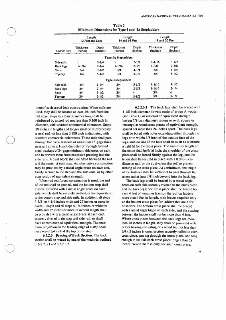
Table 2
Minimum Dimensions for Type-r and -IA Stepladders
Length Length Length
12 Feet and Less 14 and 16 Feel 18 and 20 Feet
Thickness Depth Thickness Depth Thickness Depth
Ladder Part inches) inches) inches) inches) inches) Cinches)
Type-IA Stepladders
Side rails 1 3-1/4 1 3-1/2 1-1/16 3-1/2
Back legs 1-1/16 2-1/4 1-1/16 2-3/8 1-3/8 2-3/8
Steps 3/4 3-1/2 3/4 4-1/4 3/4 4-1/4
Top cap 3/4 5-1/2 3/4 5-1/2 3/4 5-1/2
Type-l Stepladders
Side rails 3/4 3-1/4
Back legs 3 4 2-1/4
Steps 3 4 3-1/2
Top cap 3/4 5·1/2
thereof such as rod-lock construction. When nails areused, they shall be located at least 3/8 inch from the
rail edge. Steps less than 30 inch,?s long shall be
reinforced by a steel rod not less than 0.160 inch in
diameter, with standard commercial tolerances. Steps
30 inches in lengths and longer shall be reinforced by
a steel rod not less than 0.180 inch in diameter, with
standard commercial tolerances. These rods shall pass
through flat metal washers of minimum I8-gage thick
ness and at least I-inch diameter or through formed
steel washers of 24-gage minimum thickness on each
end to prevent them from excessive pressing into the
side rails. A truss block shall be fitted between the rod
and the center of each step. n alternative construction
may be provided by a metal angle brace on each end,
firmly secured to the step and the side rails, or by other
constuction of equivalent strength.
When rod-reinforced construction is used, the end
of the rod shall be peened, and the bottom step shall
also be provided with a metal angle brace on each
side, which shall be securely riveted, or the equivalent,
to the bottom step and side rails. In addition, aJl steps
3-5/8- to 4-1/4·inches wide and 27 inches or more in
overall length and all steps 4-1/4 inches or wider in
width and 32 inches or more in overaJlleng th shall
be provided with a metal angle brace at each end,securely riveted to the step and side rail, or shall
have construction of equivalent strength. The maxi
mum projection on the leading edge of a step shall
not exceed 3/4 inch at the top of the step.
6.2.2.3 Bracing of Back Section. The back
section shall be braced by one of the methods outlined
in 6.2.2.3.1 and 6.2.2.3.2.
3/4
3/4
3/4
3/4
3-1/2 1-1/16 3-1/2
2-5/8 1-1/16 2·1/4
4 3/4 4
5·1/2 3/4 5·1/2
6.2.2.3.1 The back legs shall be braced with1-1/8 inch diameter dowels made of group A woods
see Table 1), or material of equivalent strength,
having 7tg·inch diameter tenons or oval, square or
rectangular wood cross pieces of equivalent strength,
spaced not more than 24 inches apart. The back legs
shall be bored with holes extending either through the
legs or to within 1/8 inch of the outside face of the
legs, and the size of the hole shall be such as 10 ensure
a tight fit for the cross piece. The minimum length of
the tenon shall be 9/16 inch; the shoulder of the cross
piece shall be forced firmly against the leg, and the
tenon shall be secured in place with a O.OgO·inch·
diameter nail, or the equivalent thereof, to prevent
turning of the cross piece. At a minimum the length
of the fastener shall be sufficient to pass through the
tenon and at least 1/8 inch beyond into the back leg.
The back legs shall be braced by a metal angle
brace on each side securely riveted to the cross piece
and the back legs; one cross piece shall be braced for
each 4 feet of length or fraction thereof on ladders
more than 4 feet in length, with braces required on y
on the bottom cross piece for ladders that are 4 feet
or shorter. The bottom cross piece shall be braced
with a metal angle brace on each side, and the spacing
between the braces shall not be more than 4 feet.Where cross pieces between the back legs are more
than 28 inches in length, they shall be provided with
center bearing consisting of a wood bar not less than
3/4 x 2 inches in cross section securely nailed to each
cross piece, passing through the cross piece, and long
enough to include each cross piece longer than 28
inches. Where there is only one such cross piece,
9

7/21/2019 Ansi a14.1 Ladders
http://slidepdf.com/reader/full/ansi-a141-ladders 25/81
AMERICAN NATIONAL STANDARD AI4.1·1990·
supported by metal braces, the center bearing is not
required.
6.2.2.3.2 The back leg shall be braced with
horizontal wood bars made of group A B, C, or D
woods (see Table I), not less than 3/4 x 2-1/2 inches
in cross section, and spaced not more than 24 inches
apart. The ends of the bars shall fit into metal sockets
of not less than 24-gage (Manufacturer s Standard)steel, or other material of equivalent strength, or into
mortises of not less than 1/8 inch ±1/32 inch in depth
in the back legs. A steel rod not less than 0.160 inch in
diameter, with standard commercial tolerances, shall
pass through the back legs and the bar, and at each end
through flat metal washers at least 1 inch in diameter
and of minimum 20-gage thickness or formed steel
washers of 24-gage minimum thickness to prevent the
rod from excessi vely pressing into the back legs. The
back legs shalJ also be braced by a metal angle brace
on each side, securely riveted to the bar and to the
legs; one bar shall be so braced for at least each 4 feet
of length or fraction thereof, with braces required onlyon bottom bars for ladders that are 4 feet or shorter.
Metal sockets, when used, shall be attached to the
back legs by rivets, by means of a rod running through
the socket, or by equivalent means.
6.2.2.4 Antispl it Devices. Where a separate
hinge is not used, the back legs shall be reinforced by
a rivet through the depth of the leg above the top hinge
or pivot point. by metal plates or collars at the hinge
point. or by other means suitable for preventing split
ting of the back leg from the hinge pin to the top.
6.2.3 Typen CommercialStepladder
6.2.3.1 Dimensions. The minimum dimensions
of the parts of type· stepladders shall be as given in
Table 3 when these parts are made of group A. B, C,
orD woods.
The minimum thickness of the side rails provides
for the cutting of a groove 1/8 inch in depth with the
tolerance indicated in 6.2.1.4 and shall be increased
when grooves of greater depth are used. The minimum
thickness of the steps provides for the cutting of tread
grooves in the top surface not exceeding 1/8 inch in
width and 1/16 inch in depth and a rod-lock groove in
the underside of the step not exceeding 9/32 inch in
width and 9/32 inch in depth.
6.2.3.2 Flat Steps. Steps shall be secured from
front-to-back lateral movement with at least two 6dnails (minimum dimensions: 0.0858 inch in diameter
and 1-7/8 inches long) at each end. or the equivalent
thereof such as rod·lock construction. When nails are
used, they shall be located at least 3/8 inch from the
rail edge. Each step shall be reinforced by a steel rod
not less than 0 160 inch in diameter, with smndard
commercial tolerances, which shall pass through flat
metal washers of minimum 20-gage thickness and at
least 1 inch diameter or through fonned steel washers
of 24-gage minimum thickness on each end to prevent
the rod from excessively pressing into the side rails.
A truss block shall be fitted between the steel rodand the qenter of each step. Alternative construction
may be provided by a metal angle brace on each end,
ftrmly riveted to the step and side rail, or by other
construction of equivalent strength.
Where rod reinforced construction is used, the end
of the rod shall be peened, and the bottom step shall
also be provided with a metal angle brace on each
side. which shall be securely riveted, or the equivalent.
to the bottom step and side rails. In addition, all steps
27 inches or more in overall length shall be provided
with a metal angle brace at each end, securely riveted
to the step and side rails, or shall have construction of
equivalent strength.·The maximum projection on the
leading edge of a step shall not exceed 3/4 inch at the
top of the step.
6.2.2.3 Bracing of ack Section. The back
section shall be braced by one of the methods given
in 6.2.3.3.1 through 6.2.3.3.3.
Table 3
Minimum Dimensions for Type-II Stepladders
Length 3 to 8 Feet Length 10 Feet Length 12 Feet
Thickness Depth Thickness Depth Thickness DepthLadder Part (inches) (inches) (inches) (inches) (inches) (inches)
Side rails 3/4 2-5/8 3/4 2-5/8 3/4 3
Back legs 3/4 1-5/8 3/4 1-3/4 3/4 2
Steps 3/4 3-1/4 3/4 3-1/4 3/4 3-1/2
Top cap 3/4 5 3/4 5 3/4 5
20

7/21/2019 Ansi a14.1 Ladders
http://slidepdf.com/reader/full/ansi-a141-ladders 26/81
)
6.2.3.3.1 The back legs shall be braced with
cross pieces consisting of 7/8-inch-diameter dowels
made of group A woods see Table 1). or material of
equivalent strength, having 5 / 8 i n c h ~ d i a r n e t e r tenons
finnly secured in the back legs and spaced not more
than 12 inches apart. The back legs shall be bored with
holes extending either through the legs or to within
1/8 inch of the outside face of the legs, and the size
of the hole shall be such as to ensure a tight fit for the
dowel. The minimum length of the tenon shall by 9/16
inch. The shoulder of the dowel shall be forced firmly
against the leg. and the tenon shall be secured in place
with a O.080-inch-diameter nail, or the equivalent
thereof, to prevent turning of the dowel. At a mini
mum. the length of the fastener shall be sufficient to
pass through the tenon and at least 1 8 inch beyond
into the back leg.
A bar connecting two or more of the dowels shall
be provided on all ladders of 6-foot length or more.
The cross-sectional dimensions of the bar shall be the
same as the cross-sectional dimensions of the back
legs, and the dowels shall pass through holes at the
centerline of the bar. The bar shall be attached at the
center of the length of the lower two dowels on a
6-foot ladder and shall extend upward one dowel
for each additional 2 feet of length.
6.2.3.3.2 The back legs shall be braced with
wood dowels as set forth in 6.2.3.3.1 plus an inverted
V bracing of 3/4 x 1-1/2 inch material through which
the dowels extend; the length of the V shall extend
two-thirds of the way up the back.
6.2.3.3.3 The back legs shall be braced with
horizontal wood bars made up of group A, B, C, D, orE woods see Table 1) not less than 3/4 x 2 inches in
cross section, the ends of which shall fit into metal
sockets of not less than 24-gage (Manufacturer s
Standard) steel, or other material of equivalent
strength, or into mortises in the back l egs not less
than 1/8 inch ±1/32 inch in depth. The bars shall be
reinforced by steel rods not less than 0.160 inch in
diameter, with standard commercial tolerances, which
shaH pass through the back legs and the bar, and at
each end through flat metal washers at least 1 inch in
diameter and 20-gage minimum thickness. or through
formed steel washers of 24-gage minimum thickness,
10 prevent the rods from excessively pressing into theback legs. The spacing of such bars shall not exceed 3
feet, and there shall be at least one bar on 3- and 4-foOl
ladders, two bars on 5- and 6 ~ f o O l ladders, three bars
on and 8-footladders, and four bars on 10- and
12- 00t ladders. The bottom bar shall be not more than
18 inches from the bottom of the ladder, and where
only one bar is used, it shall be braced by a metal
AMERICAN NATIONAL STANDARD AI4.1·1990
angle brace on each end securely riveted 10 the bar and
the back leg, or by construction of equivalent strength.
6.2.3 4 Antisplit Devices. Where a separate
hinge is not used, each back leg shall be rein forced by
a rivet through the depth of the leg above the top hinge
or pivot point. by metal pla tes or collars at the hinge
point, or by other means suitable for preventing split
ting of the back leg from the hinge pin to the top.
6.2.4 Type l l Household Stepladder
6.2.4.1 Dimensions. The minimum dimensions
of the parts of the type-III stepladder shall be as given
in Table 4 when these parts are made of group A. B
C, or D woods.
The minimum thickness of the side rails provides
for the cutting of a groove 1/8 inch in depth with the
tolerance indicated in 6.2. 1.4 and shall be increased
when grooves of greater depth are used. The minimum
thickness of the steps provides for the cutting of tread
grooves in the top surface nor exceeding 1/8 inch in
width and 1/16 inch in depth and a rod-lock groove in
the underside of the step not exceeding 1/4 inch in
width and 1/4 inch in depth.
6.2.4.2 Flat Steps. Steps shall be secured from
f r o n t ~ t o b a c k lateral movement with at least one 6d
nail minimum dimensions: 0.0858 inch in diameter
and 1-7/8 inches long) at each end, or the equivalent
thereo f such as rod-lock construction. When nails are
used. they shall be loca ted at least 3/8 inch from the
rail edge. Each step shall be reinforced y a sreel rod
not less than 0.160 inch in diameter, with standard
commercial tolerances. which shall pass through flat
metal washers of a minimum 20-gage thickness or
formed steel washers o f 4 ~ g a g e minimum thickness
and at least one inch in diameter on each end to
prevent the rod from excessively pressing into the
side rails. Alternate construction may be provided by
a metal brace at each end securely riveted to the step
and side rail, or by other construction of equivalent
strength.
Where rod reinforced construction is used. the end
of the rod shall be peened, and the bottom step shall be
provided further with a metal angle brace on each end
Table 4
Minimum Dimensions for Type.III Stepladders
Length 3 to 6 Feet
Thickness DepthLadder Pan inches) inches)
Side rails 3 4 2-1/2
Back legs 3/4 1-5/1 6
Steps 3/4 3
Top cap 3 4 5
2
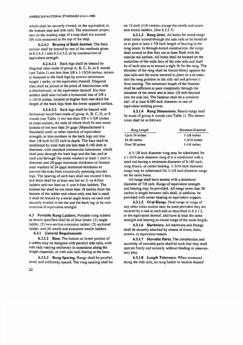
7/21/2019 Ansi a14.1 Ladders
http://slidepdf.com/reader/full/ansi-a141-ladders 27/81
AMERICAN NATIONAL STANDARD AI4.1-1990
which shall be securely riveted, or the equivalent, to
the bottom step and side rails. The maximum projec
tion on the leading edge of a step shall riot exceed
3/4 inch measured at the top of the step.
6.2.4.3 Bracing of Back Section. The back
section shall be braced by one of the methods given
in 6.2.4.3.1 and 6.2.4.3.2, or by construction of
equivalent strength.
6.2.4.3.1 Back legs shall be braced by
diagonal slats made of group A, B, C. D, or E woods
(see Table 1) not less than 3/8 x 1-15/16 inches, secure
ly fastened to the back legs by screws (minimum
length 1 nch . or the equivalent thereof. Diagonal
sfats shall be joined at the point of intersection with
a clinched nail, or the equivalent thereof. Six-foot
ladders shall also include a horizontal slat of 3/8 x1-15/16 inches. located no higher than one-third the
length of the back legs from the lower support surface.
6.2.4.3.2 Back legs shall be braced with
horizontal wood bars made of group A, B, C, D. or Ewoods (see Table I not less than 5/8 x 1 5/8 inches
in cross section, the ends of which shall fit into metal
sockets of not less than 24-gage (Manufacturer s
Standard) steel, or other material of equivalent
strength, or into monises in the back legs not less
than 1/8 inch ±1/32 inch in depth. The bars shall be
reinforced b) steel rods not less than 0.160 inch in
diameter, with standard commercial tolerances. whichshall pass through the back legs and the bar, and at
each end through flat metal washers at least I inch in
diameter and 20-gage minimum thickness or fanned
steel washers of 24-gage minimum thickness to
prevent the rods from excessively pressing into the
legs. The spacing of such bars shall not exceed 3 feet,
and there shall be at least one bar on 3- or 4-foot
ladders and two bars on 5- and 6-foot ladders. The
bottom bar shall be not more than 18 inches from the
bottom of the ladder and where anI) one bar is used.
it shall be braced by a metal angle,brace on each end
securely riveted to the bar and the back leg or by con
struction of equivalent strength.
6.3 Portable Rung Ladders. PonabJe rung ladders
as herein specified shall be of four kinds: (1) single
ladder. (2) two-section extension ladder. (3) sectional
ladder, and (4) trestle and extension trestle ladders.
6.3.1 General Requirements
6.3.1.1 Base. The bottom or lower portion of
a ladder may be designed with parallel side rails, with
side rails varying uniformly in separation along the
length (tapered), or with side rails flaring at the base.
6.3.1.2 Rung Spacing. Rungs shall be parallel,
level, and uniformly spaced. The rung spacing shall be
22
on 12-inch ±1{4 centers, except for trestle and exten
sion trestle ladders. (See 6.3.5.7)
6.3.1.3 Rung Joint. All holes for wood rungs
shall either extend through the side rails or be bored so
as to give at least a 7/8 inch length of bearing to the
rung tenon. In through-bored construction, the rungs
shall extend so that they are at least flush with the
outside rail surface. All holes shall be located on thecenterline of the wide face of the side rails and shall
be of such size as to ensure a tight fit for the rung. The
shoulder of the rung shall be forced firmly against the
side rails and the tenon secured in place so a to main
tain the rung position in the side rail and prevent it
from turning. The minimum length of the fastener
shall be sufficient to pass completely through the
diameter of the tenon and at least 1/8 inch beyond
into the side rail. The fastener shall be a common
nail of at least 0.080 inch diameter or one of
equivalent holding power.
6.3.1.4 Rung Dimensions. Round rungs shall
be made of group A woods (see Table I . The dimensions shall be as follows:
Rung Length
Up to 24 inches
24-28 inches
Over 28 inches
Minimum Diameter
1 1/8 inches
1 3/16 inches
1-1/4 inches
A 1 1/8 inch diameter rung may be substituted for
a 1-3/16-inch diameter rung if it is reinforced with a
steel rod having a minimum diameter of 0.160 inch.
rung braces, or center bearing. 1-3/16-inch diameter
rungs may be substituted for 1-1/4 inch diameter rungs
on the same basis.All rungs shall have tenons with a minimum
diameter of 7/8 inch. Rungs of equivalent strength
and bearing may be provided. All rungs more than 28
inches in length between rails shall, in addition. be
provided with center bearing or equiv.alent suppon.
6.3.1.5 Oval Rungs. Oval rungs or rungs of
any other cross section may be used provided they are
secured by a nail at each end as described in 6.3.1.3.
or the equivalent thereof. and have at least the same
strength and bearing as round rungs of the same length.
6.3.1.6 Hardware. LI hardware and fittings
shaH be securely attached by means of rivets, bolts.
screws, or equivalent means.
6.3.1.7 Movable Parts. The construction and
assembly of movable parts shan be such that they shall
operate freely and securely without binding or unneces
sary play.
6.3.1.8 Length Tolerance. When measured
along the side rails, no rung ladder or section thereof

7/21/2019 Ansi a14.1 Ladders
http://slidepdf.com/reader/full/ansi-a141-ladders 28/81
~ )
)
shall be more than 3 inches shorter than the specified
length.
6.3.1.9 Sboes or Antislip Devices. Shoes or
antislip devices are optional equipment. When in
stalled by the manufacturer of the ladder at the request
of the user, they shall be securely bolted, nailed,
riveted, or attached by equivalent construction to the
side rails, with the exception of elastic boot-type
shoes that are properly fined.
6.3.2 Single Ladder
6.3.2.1 Length. Single ladders as hereinafter
specified shall be of four types and lengths: I) Type
IA and shall not exceed 30 feet, (2) Type II shall not
exceed 20 feet, and (3) Type III shall not exceed 14
feet. The size shall be detennined by the overall length
measured along the side rail.
6.3.2.2 Side-Rail Dimensions. The minimum
dimensions of the side rails of Type-IA, -1 -II, and-III
single ladders shall be not less than those specifi ed in
Table 5 when the rails are made of group B, C, or D
woods.
6.3.2.3 Reinforced Rails. Smaller side rails
will be acceptable in all ladders of this type when the
rails are reinforced on the underside by a steel wire,
rod, or strap running their entire length and adequately
secured thereto. Where such reinforcement is used,
the reinforced rails shall be equivalent in strength to
the side rails specified in 6.3.2.2 and shall be marked
as being electrically conductive.
6.3.2.4 Width. The width between the side
rails at the base, inside to inside, shall be at least
11-1/2 inches for all ladders up to and including 10
feet. Such minimum widths shall be increased at
least 1/4 inch for each additional 2 feet of length.
6.3.3 Two-Section Extension Ladder
6.3.3.1 Sizes. Two-section extension ladders
as hereinafter specified shall be of four types and
sizes: I) Type IA and shall not exceed 60 feel, (2)
Type II shall nol exceed 40 feet, and 3) Type III shall
not exceed 28 feet. These ladders shall consist of two
sections; the top section nearest the climber shall fit
within the side rails of the bottom section and be
arranged in such a manner that the upper section can
be raised and lowered. The size shall be determined
by the sum of the lengths of the sections measured
along the side rails.
6.3.3.2 Side-Rail Dimensions. The minimum
dimensions of the side rails of Type-LA, -I, -II, and-III
two-section extension ladders shall be not less than
those specified in Table 6 when the rails are made of
group B C or D woods.
6.3.3.3 Overlap. The minimum dimensions of
side rails set forth in Table 6 are based on the maxi-
AMERICAN NATIONAL STANDARD A \4. \·\9'10
Table 5
Minimum Dimensions of
Side Rails for Single Ladders
Rail Dimensions
Length of Ladder
(feel)Thickness
(inches)
Type JA Group B Woods
Up to and including 16 1-1116
Over 16 up 10 and including 20 1-1/16
Over 20, up 10 and including 30 1-5/16
Type IA - Group C Woods
Up to and including 16 1-1/16
Over 16, up 1 and including 20 1 1/8
Over 20 up 10 and including 30 1-3/8
Type IA - Group D Woods
Up to and including 16 1-1/16
Over 16 up to and including 20 1-5/16
Over 20. up 10 and including 30 1 3/8
Type 1- Group B Woods
Up 10 and including 16 1-1/16
Over 16, up to and including 20 1-1116
Over 20, up to and including 30 1-1/4
Type 1- Group C Woods
Up to and including 16 1-1/16
Over 16, up to and including 20 1-1/8
Over 20, up 10 and including 30 1-1/4
Type I • Group 0 Woods
Up to and including 14 1 1116
Over 14. up to and including 18 1-118
Over 18, up to and including 22 1-1/8
Over 22, up 10 and including 30 1 5/16
Type n . Group B Woods
Up to and including 18 1-1/16
Over 18 up 10 and including 20 1-1/16
Type II Group C Woods
Up to and including 16 1 1/16
Over 16 up 10 and including 20 1-l/16
Type II - Group D Woods
Up 10 and including 14 1-1/16
Over 14, up to and including 20 1-1/8
Type 111- Group B C, or 0 Woods
Up to and including 14 1-1/16
Depth
(inches)
2 1/2
2-3/4
3
2-5/8
2 3/4
3
2-3/4
2 3/4
3 1/4
2-1/4
2-1/2
2-3/4
2-1/4
2-\ 2
2-718
2-1/4
2-1 2
2 3/4
3
2-1/42-3/8
2 1/4
2-1/2
2-1/4
2-1/2
2-1/4
mum working length, which is the size of the ladder
less the minimum overlap. The minimum overlap
shall be as given in Table 7.
6.3.3.4 Overlap Control. Extension ladders
shall be constructed in such a manner that the ladder
cannpl be used with an overlap less than the minimum
23

7/21/2019 Ansi a14.1 Ladders
http://slidepdf.com/reader/full/ansi-a141-ladders 29/81
AMERICAN NATIONAL STANDARD A14.1 1990
Table 6
Minimum Dimensions ofSide Rails for Two-Section Extension Ladders
Rail Dimensions Rail Dimensions
Overall LengthDepth
Overall LengthDeplhof Ladder Thickness of Ladder Thickness
(feet) (inches) (inches) (feet) (inches) (inches)
Type IA - Group B Woods Type·Group D Woods
16 and 20 1 1/16 2-1/2 6 1.1/16 2-1/424 1·1/16 2-3/4 20 1.1/16 2-1/2
28 1 5/16 2-3/4 24 1·1/8 2-3/4
32 1 1/4 3 28 1-5/16 2·3/4
36 1 3/8 3-1/8 32 1 5116 340 1 3/8 3·1/4 36 1 3/8 3-1/844 1 3/8 3-1/2 40 1 3/8 3·1/448 1·3/B 3·S/B 44 1.3/8 3-1/252 1·3/B 3 7/B 48 1 3/8 3-1/2
60 1 3/B 4.1/4 52 1 3/8 3·15/16Type lA • Group C Woods 60 1 3/4 3-7/8
16 and 20 1·1/16 2·5/8 Type II · Group B Woods24 1 1/8 2-3/4 16 and 20 1.1/16 2-1/428 1·3/8 2·3/4 24 1·1/16 2-3/832 1 3/8 3 28 1 1116 2-5/836 1 3/8 3 3116 32 1 1/4 2-5/840 1 3/8 3-1/4 36 1 3/8 2-3/444 1 3/8 3-9/16 40 1 5116 2-7/848 1 3/8 3·3/4 Type II • Group C Woods52 1 3/8 4 16and20 1·1/16 2·1/460 1 1/2 4-1/4 24 1·1/16 2-1/2
Type IA· Group D Woods 28 1-1/16 2·3/416and 20 1·1/16 2-3/4 32 1·1/4 2·3/4
24 1 5/16 2·3/4 36 1·5/16 · n
28 1·5/16 3 40 1·5/16 332 1.3/B 3·3/16 Type II - Group D Woods36 1 3/8 3·7{16 16 1·1/16 2·1/440 1 3/8 3·5/8 20 1·1 l6 2·3/844 1 3/8 3 7/8 24 1 1/16 2·5/848 1 3/8 4·1/16 28 1·3/16 2-3/452 1 3/8 4·5/16 32 1 3/8 2 3/4
60 1 3/4 4-1/4 36 1 3/8 3
Type 1 Group B Woods 40 1 3/8 3·\/816and 20 1 1/16 2·1/4 Type III - Group B Woods24 1 1/16 2·1/2 16. 20. and 24 1-1/16 2-1/428 1·1/16 2·3/4 28 1-1/16 2·1/232 1·5/16 2·3/4 Type III - Group C Woods36 1 5/16 2-7/8 16 and 20 1·1/16 2·1/440 1·5/16 3 24 1·1/16 2·3/844 1·3/8 3 1/4 28 1·1/16 2-5/848 1·3/8 3 3/8 Type III - Group D Woods52 \-3/8 3-1/2 16 and 20 1 1/16 2-1/460 1·1/2 3-3/4 24 1 1/16 2-1/2
Type I •Group C Woods 28 1 1/16 2-3/46 \·1/16 2-1/4
20 1 1/16 2-3/824 1 1116 2-5/828 1 1/8 2-3/432 1 3/8 2·3/4
36 1 5/16 340 1 3/8 344 1·3/8 3·3/848 1 3/8 3-1/252 1 3/8 3-5/860 1 5/8 3·3/4
24

7/21/2019 Ansi a14.1 Ladders
http://slidepdf.com/reader/full/ansi-a141-ladders 30/81
Ladder
Type
lA and I
Table 7
Minimum Overlap for
Two-Section Extension Ladders
Size of Ladder
(feet)
Up to and including 32Over 32. up to and including 36
Over 36. up to and including 48
Over 48. up to and including 60Up to and including 32
Over 32. up to and including 36
Over 36 up to and including 4Q
Up to and including 28
·Subject to tolerance as specified in 6.3.I.B.
Table 8
MinimumOverlap·
(feet)
34
5634
53
Minimum Distance between Points of Bearing
for Two-Section Extension Ladders
Minimum Overlap·(feet)
3
4
5
6
Minimum Distance between
Points of Bearing(inches)
2638
50
62
As described in 6.3.3.3 and Table 7.
specified in Table 7. The use of the pulley location to
limit the overlap shall not be considered as complying
with this requirement. Ladde r lock location. mecha
nical stops, or the equivalent are acceptable.6.3.3.5 Bearing Points The ladder shall be
constructed so that the minimum distance between the
points of bearing is as given in Table 8. The points of
bearing are nonnally the points at which the rails of
the top section bear against the support brackets or
guides attached to the top of the bottom section and
the points at which the rails of the top section bear
against a rung of the bottom section.
6.3.3.6 Number of Guide Irons There shall
be at least two pairs of guide irons on all two-section
extension ladders, except for type-III ladders not over
16 feet in length with push-up locks. Both pairs can be
placed near the top of the bottom section (at least 18
inches apart), or one pair can be placed near the top of
the bottom section and the other pair near the bottom
of the top section.
6.3.3.7 Reinforced Rails Smaller side rails
will be acceptable in all two-section extension ladders
when the rails are reinforced on the underside by a
steel wire, rod. or strap running their entire length and
AMERICAN NATIONAL STANDARD A14. 1·1 <}I} )
adequately secured thereto. Where such reinforcement
s used. the reinforced rails shall be equivalent in
strength to the side rails specified in Table 6 and
shall be marked on both top and bottom sections as
being eleclIically conductive.
6.3.3.8 Width. The minimum distance be
tween side railsof
the bottom section. inside to inside.shall be 14-1/2 inches on ladders up to and including
28 feet; 16 inches on all ladders over 28 feet. up to
and including 40 feet; and 18 inches on all ladders
over 40 feet.
6.3.3.9 Hardware All locks and guide irons
shall be made of metal or other material and shall be
of such construction and strength as to develop the
full strength of the side rails. All locks shall be posi
tive in their action and shall meet all performance
tests. Locks may be of any design, such as gravit) ,
spring- action, rope-operated. or stationary types.
A section incorporating locks in a manner that
results in the elimination of a rung in the section orone not intended for separate use because of non
compliance with single ladder requirements shall
have a pennanent marking in letters not less than
1/8 inch high:
Caution - This Ladder Section Is Not DeSigned
for Separate Use
or pennanently attached stops shall be provided to
prevent removal of the section. Permanently artached
stops are considered to be those that would require cut
ting. drilling, or similar forceable means for removal.
The guide irons shall be securely attached and so
placed as to prevent the upper section from tipping or
falling out while the ladder is raised, lowered. or inuse. Minimum dimensions of guide irons shall be as
shown in Table 9.
The primary guides are those placed nearest the top
of the bottom section. The secondary guides are those
placed lower down on the top of the bottom section or
those placed near the bottom of the top section.
6.3.3.10 Rope and Pulley. Extension ladders
may be equipped with a rope and pulley, which shall
Table 9
Guide Iron Dimensions for Extension Ladders
Primary SecondarySize of Ladder Minimum Minimum
(feet) (inches) (inches)
Up to and including 28 3/16 x I-J/4 3/l6 x 1Over 28 up to and
including 40 3/16x 1 1/2 3/16 x 1-1/4
Over 40. up to and
including 60 3/16 x 1-3/4 3/16 x 1 1/2
25

7/21/2019 Ansi a14.1 Ladders
http://slidepdf.com/reader/full/ansi-a141-ladders 31/81
AMERICAN NATIONAL STANDARD AI4.1-1990
be securely attached to the ladder in such a manner as
not to weaken either the rungs or the side rails. The
fastening means shall not be construed as weakening
the rungs, provided the minimum diameter of the
rungs with the fastening means attached meets the
requirements in 6.3.1.4. The pulley shall not be less
than I inch in diameter at the base of the sheave.
The rope used with the pulley shall not be less than a
nominal 5/16 inch in diameter, shall have a minimum
breaking strength of 560 pounds; and shall be of
sufficient length for the purpose intended.
6.3.4 Sectional Ladder6.3.4.1 Length. Assembled combinations of
sectional ladders longer than the lengths specified in
6.3.4.2 shall not be used. The size shall be detennined
by the overall length of the assembled sections. The
size of any individual section shall be delennined by
the length of the section, measured along a side rail,
not including the small amount of material at the end
or ends needed for attaching. Each section shall be
marked to indicate the maximum assembled length
in accordance with Table 10.
6.3.4.2 Side-Rail Dimensions. The minimum
dimensions of the side rails of type-lA, -I and-II
sectional ladders shall be not less than those specified
in Table \ when the rails are made of group B. C,
or 0 woods.
Table 10
Minimum Dimensions of
Side Rails for Sectional Ladders
Rail Dimensions
Assembled Lengthof Ladder
(feet)
Thickness(inches)
Type lA - Group Band C Woods
Depth
(inches)
Up to and including 21 1-1/8 2-7/8
Over 21. up to and including 31 1-1/8 3-1/2
Type lA - Group D Woods
Up to and including 21 1-1/8 3
Over 21. up to and including 31 1-1/8 3-3/4
Type I - Group Band C Woods
Up to and including 21 1·1/8 2-3/4
Over 21. up to and including 31 1-1/8 3·1/8
Type I - Group Woods
Up to and including 21 1-1/8 2-3/4
Over 21, up to and including 31 1· 1/8 3-3/8
Type II • Group B, C, and D Woods
Up to and including 21 1-1/8 2-3/4
Over 21. up to and including 31 1- 1/8 3-1/8
26
6.3.4.3 Width. Sectional ladders shall have
either (I) straight sides slightly converging toward the
top of each section, or 2) flaring sides at the bollom
of the first (or bottom section, with the top section
having side rails that converge to a width that shull be
no less than 4 inches. Except for the top section. Ihe
minimum width between side rails shall be inches.
6.3.4.4 Connecting Joint. Adjacent sectionsshall be joined by means of a groove in the bOllom
end of each rail of the upper of the two sections that
sets firmly, outside the side rails, over extensions of
the topmost rung of the next lower section. and. at
the same time. a groove in the top end of each rail of
the lower of the two sections that sets finnly. inside
the side rails, over the bottom rung of the section
immediately above.
The distance between the topmost rung of one
section and the bottom rung of the section immediately
above it shall not be less than I foot. The fit between
the rail grooves and the rungs shall be such as to provide a good fit without binding or unnecessary play.
The grooved ends of the sections shall be rein
forced with a metal plate of not less than IS-gage
(Manufacturer s Standard) material, properly secured
thereto. and a rivet adjacent to the groove, extending
through the depth of the rail, or the equivalent thereof.
6.3.5 Trestle and Extension Trestle Ladder -Type I
6.3.5.1 Size. Trestle ladders, or extension
sections or base sections of extension trestle ladders,
shall not be longer than 20 feel. The extension-section
size shall not be greater than the base-section size.
When measured along the front edge of the side rail,no section of the trestle ladder shall be more than 3
inches shoner than its specified length.
6.3.5.1.1 Trestle Ladder. The size of a
trestle ladder shall be detennined by the length of
the side rails measured along the front edge.
6.3.5.1.2 Extension Trestle Ladder. The
size of an extension trestle ladder shall be detennined
by the length of the trestle ladqer base along the front
edge of the side rail plus the allowable extended length
of the extension section measured along its side rail.
The extension section of the extension trestle ladder
shall have parallel sides.6.3.5.2 Side-Rail Dimensions. The minimum
dimensions of the side rails of the trestle ladder or of
the base sections of the extension trestle ladder, shall
be as given in Table I I for group B, C, or 0 woods.
The minimum dimensions of the side rails of the
extension section of the extension trestle ladder shall
be as given in Table 12 for group B, C, or 0 woods.

7/21/2019 Ansi a14.1 Ladders
http://slidepdf.com/reader/full/ansi-a141-ladders 32/81
~/
/
6.3.5.3 Slope. Trestle ladders and base sections
of extension trestle ladders shall. be so spread that
when in an open position, the spread of the trestle at
lhe bottom, inside-lo-inside, shall be at least 5-1/2
inches pe r foot of base-section side rail.
6.3.5.4 Width. The minimum width between
side rails of the extension section of the extensiontrestle ladders at any point shall not be less than 12-1/2
inches. The minimum width between side rails at the
top of trestle ladders and of base sections of extension
trestle ladders shall be not Jess than 15-1/2 inches, and
from top to bottom the side rails sha ll spread at least
1-1/4 inches per foot of side-rail length.
6.3.5.5 Extension Trestle Overlap. Based on
the size of the ladder, the extension sect ion of the
extension trestle ladder, when fully extend ed, shall
Table 11
Minimum Dimensions of Side Rails
for Trestle Ladders or Base Sections
of Extension Trestle Ladders
Rail DimensionsSize of
Base Section Thickness Depth
feet) (inches) (inches)
Up to and including 16 1-5/16 2-3/4Over 16, up to andincluding 20 1-5/16 3
Table 12
Minimum Dimensions of Side Rails
for Extension Sections
of Extension Trestle Ladders
Rail DimensionsSize of
Base Section Thickness Depth
(feet) (inches) (inches)
Up to nd including 12 1-5/16 2-1/4Over 12, up to and
including 16 1-5/16 2-1/2
Over 16. up to andincluding 20 1-5/16 2-3/4
Table 13Required Extension Trestle Ladder Overlap
Size of
Base Sectionfeet)
6, up to and including 8Over 8, up to and including 12
Over 12, up to nd including 16
Over 16, up to and including 20
Minimum RequiredOverlap*
feet)
34
56
*Subject to tolerance as specified in 6.3.5.1.
AMERICAN NATIONAL STANDARD t\14.1·1 :l lO
overlap the base section by the number of feet indi
cated in Table 13.
6.3.5.6 Hinge Joint. The lOpS of the side mils
of the trestle ladder and of the base section of the
extension trestle ladder shall be beveled. or o
equivalent construction, and shall be provided further
with a metal hinge to prevent spreading. (See 5.3)6.3.5.7 Spreaders. A metal spreader or lock
ing device (see 5.3) of sufficient size and strength to
securely hold the front and back sections in the open
position shall be a component of each trestle ladder.
When double sets of spreaders are used, the lower
set shall not be more than 6-1/2 feet above the lower
support surface. On extension trestles where the
extension guidance system serves as the spreaders. its
location may be more than 6-1/2 feet above the base.
6.3.5.8 Rung Spacing. Rungs shall be parallcl
and level. On the trestle ladder, or on the base section
of the extension trestle ladder, rungs shall be spaced
not less than 8 inches or more than 18 inches apart; on
the extension section of the extension trest Ie ladder,
rungs shall be spaced not less than 6 inches or more
than 12 inches apart.
6.3.5.9 Overlap Control. Extension trestle
ladders shall be constructed in such a manner thaI the
ladder cannot be used with an overlap of less than the
minimum specified in Table 13. Designs employing
ladder lock locations, mechanical stops, or the
equivalent are acceptable.
6.3.5.10 Extension-Section Locking Device.
The extension locking device shall be made of metal
and shall be of such design and strength as to develop
the full strength of the side rails.
6.4 Special-Purpose Ladders. All special-purpose
ladders shall comply with the appropriate require
ments given in 6.1, 6.2, and 6.3, except as hereinafter
modified in 6.4.
6.4.1 Platform Ladder. A platform ladd er is a
modification of a portable ladder with a working
platform provided near the lOp. The size of a platform
ladder shall be determined by the length of the front
edge of the side rail from the bottom of the ladder to
the top of the platform with a tolerance of ±2 inches.
6.4.1.1 Platform ladders shall be constructed
in accordance with the requirments for Type-1A or -I
stepladders (see 6.2.2) or in accordance with the
requirements of Type-II stepladders see 6.2.3).
6.4.1.2 The slope of the back section shall be
such that a vertical from the back edge of the platform
will strike the floor at a distance, measured toward the
front section, of not less than 3 inches from the inside
edge of the base of the back section.
27

7/21/2019 Ansi a14.1 Ladders
http://slidepdf.com/reader/full/ansi-a141-ladders 33/81
AMERICAN NATIONAL STANDARD AI4.l-1990
Table 14
Minimum Dimensions of Side Railsand Rungs for Masons Ladders
Side Rails
Length ofLadder
feet)
Thickness
inches)Up to and including 22
Over 22, up to and including 40
1-5/8
1 5/8
6.4.1.3 The minimum width between side rails
at the platform shall be not less than 15 inches.
6.4.1.4 The back legs and side rails shall
extend at least 20 inches of vertical height above the
top of the platform and shall be connected with the
top cap to fonn a three-sided rail, or equivalent
construction shall be provided.
0.4.1.5 Platfonns shall be constructed so thatthey are capable of supporting a load of 1200 pounds
for type-IA. 1000 pounds for type-I, and 900 pounds
for type-ll ladders, when the load is placed on a 3-1/2
inch wide block across the full width of the platfonn
at the center. The width of the platform is from side to
side. The platform shall withstand the load without
failure or permanent deformation in excess of 1/100of the length of the platfonn. The test unit shall be
destroyed immediately after testing.
6.4.1.6 A separate spreader may be omitted
from type-Il platform ladders in which the height to
the platform is 6 feet or less. If the spreader is omitted,
the platfonn shall be so designed as to function as aspreader or locking device to hold the front and back
sections securely in an open position, with the connec
tion between the side rails and back legs being through
the metal pans of the platform. The wood pans of a
combined wood and metal platform functioning as a
spreader shall not be depended upon to contribute to
the spreading or locking action. The spreader, or the
lower set of a double set of spreaders when used, shall
not be more than 6-1/2 feet above the lower supportsurface.
6.4.2 Painter s Stepladder - Type II
6.4.2.1 Painters stepladders longer than 12
feet shall not be supplied. The length of a painter sstepladder shall be determined by the length of the
front rail measured along the front edge from the
bottom of the ladder to the top of the top step. The
measurement shall be within 2 inches of the specifiedsize of the ladder.
6.4.2.2 Painters stepladders shall be con
structed in accordance with the minimum requirements
28
Depth
inches)3-5/8
4-1/2
Rung Diameter
inches)1 3/8
1 3/8
Tenon Diameter
inches)
of type-II stepladders (see 6.2.3), except for the
following:
I) The top cap may be omitted.
2) A rope spreader may be substituted for the metal
spreader required in 6.2.1.6. The rope shall not be less
than No.6 sash cord or its equivalent.
6.4.3 Mason s Ladder - Type IA. Amason s
ladder is a special type of single ladder intended foruse in heavy construction work.
6.4.3.1 Masons ladders longer than 40 feet
shall not be supplied. When measured along the side
rail, the size of the ladder shall not be more than 3
inches shorter than the specified length.
6.4.3.2 The minimum dimensions of the side
rails, when made of group B, C, or D woods, and ofthe rungs (group woods) shall be as given in Table
14.
6.4.3.3 The width between the side rails at the
bottom rung, inside to inside, shall be not less than 2
inches for all ladders up to and including 10 feel. Such
minimum widths shall be increased by at least 1/4 inchfor each additional 2 feet of length.
6.4.3.4 Rungs shall be parallel and level and
shall be uniformly spaced not less than 8 inches or
more than 12 inches center to center. When rungs are
28 inches or more in length between side rails, they
shall in addition be provided with center bearing.
6.4.4 Other Types o Special Ladders. Other
types of special ladders, such as cleat ladders. trolley
and rolling ladders, industrial tripod stepladders,
three-section extension ladders, fruit-pickers ladders.
combination step and extension ladders, stockroom
stepladders, aisleway stepladders, shelf ladders.self-leveling ladders, double front ladders, and
library ladders, are not covered in this standard.
6.5 Step Stools (Ladder Type)
6 5 1 Step Stool Size 32 Inches Maximum).
Stepstool size shall be measured along the front edge
of the fronl side rail including the top cap and feel,
with a tolerance of ±1/2 inch. The front side rails may

7/21/2019 Ansi a14.1 Ladders
http://slidepdf.com/reader/full/ansi-a141-ladders 34/81
continue around and over the top cap, but such side
rail extension is not considered as part of the size.
6.5.2 Slope. Slope is the angle of the side rails or
back legs with respect to the vertical, and is expressed
as the horizontal deviation from the vertical per unit
length of the member. Step stools shall be constructed
so that when in the open position, the slopeof
the frontsection shall e not less than 4 inches and the slope of
the back section shall not be less than 2-1/2 inches per
foot of back leg length.
6.5.3 Width and Spread The minimum clear
width between side rails at the top step shall be 10-1/2
inches. The minimum outside width at the top cap
shall e 12 inches. From top to bottom, the spread
between the side rails shall increase a minimum of
1-1/4 inches per foot of side-rail length.
6.5.4 Steps. Excluding the interval between the
bottom step and support surface, the steps shall be
uniformly spaced at intervals of 8 to 12 inches.
6.5.5 Back Section. The back section may e
designed with any type bracing covered in 6.2.4.3,
modified to cover a 2 to 3-foot section.
6.5.6 Spreaders. A metal spreader or locking
device of sufficient size and strength to securely lock
the front and back sections in the open position shall
be a component part of each step stool. All sharp
points or edges shall be covered or removed to
protect the user.
6.5.7 Top Cap. The top cap shaH be not less than
12-inches wide, 5-1/4 inches deep, and 3/4-inch thick.
The top cap shall not be split for folding the ladder.
6.5.8 Construction. Except as noted above, step
stools ladder type) shall meet the requirements of
6.2.1. and 6.2.4 for Type-Ill ladders.
7. Test Requirements
Ladders shall meet the specifications of the foregoing
sections and. in addition, shall pass the tests described
in this section.
7.1 General
7.1.1 The test methods depicted in this section rep
resent the preferred methods to be followed in deter
mining whether a ladder confonns to the requirements
of this standard. Variations from the specific methods
depicted in the various diagrdms shall be acceptable
provided such alternate means provide equivalent
results and comply with the intent of the applicable
preferred test method. However, where the supposed
equivalent test methods yield different results, the
preferred test methods shall determine whether or not
the ladder is in conformance with the standard.
AMERICAN NATIONAL STANDARD AI4.1 1990
1 .1.2 The test requirements were developed using
statistical tolerances. Hence. where a single test result
indicates noncompliance. the lest may e repeated
utilizing a statistically justifiable number of test
samples to ultimately detennine compliance or non
compliance with the standard.
7.1.3 Many of the tests required by the standardare inherently dangerous. The American National
Standars Institute, the Al4 Committee, the A14 Sub
committees, and the A14 Task Forces neither assume
nor accept any responsibility for any injury or damage
that may occur during or as the result of tests.
wherever perfonned, whether performed in whole or
in part by the manufacturer, an outside laboratory or
consultant, the user or owner of the product. or any
other individual or organization, and whether or not
any equipment, facility. or personnel for or in connec
tion with the test is furnished by the manufacturer or
by any other such individual. consultant. laboratory. or
organization. Extreme care shall be exercised to avoidpersonal injury when setting up and conducting the
tests and when disassembling the test gear at the
conclusion of the tests.
7.1.4 Diligent effort and close attention to all
details shall be exercised in setting up and conducting
the tests. Subtle varitions in test techniques may intro
duce significant testing errors that bias the testing pro
gram. Personnel inexperienced in ladddcr testing, even
though otherwise professionally qualified, should be
especially careful to follow the preferred test methods.
7.1.5 Design verification tests shall be conducted
during the initial evaluation of a specific product
design and thereafter whenever there is a change in
the design, method of manufacture, or material. It is
not intended that design verification tests shall be
conducted on ladders that have been in use or sub
jected to prior damage, misuse, or abuse. Ladders
subjected to design verification tests are not intended
for subsequent use.
7 1 6 uality control tests shall be conducted
during the manufacturing process employed to
produce the ladder. Such tests normally shall not be
conducted on every ladder manufactured or on ladders
that have been in use or have been subjected to prior
damage, misuse or abuse. Certain quality control tests,
such as dimensional verifications. hardness. chemistry.
spectroscopic and mechanical properties tests may be
conducted on ladders subsequent to their use when
done with extreme care by properly qualified profes
sionals following applicable STM Standards for
such tests, where proper recognition is given to the
influence on the tests results of prior use in the test
method itself. Except where the quality control teste;
29

7/21/2019 Ansi a14.1 Ladders
http://slidepdf.com/reader/full/ansi-a141-ladders 35/81
AMERICAN NATIONAL STANDARD A14.1-1990
NOTES:
A-C PL lWOOO SURFACE(NOTE I)
DEAD LOAD(NOTE 2)
A·C P ~ Y W O O SURFACE
(NOTE
l) This illustration shows the lest setup before the load s
applied.
2) The test platfonn follows the test load as the ladder
deflects into the wall.
3) The angle of inclination shaH be 75-1/2°, excep t that
for combination ladders in the extension-ladder orientation a
slightly modified angle shall be used so that the tread por·
tions of the steps are horizontal level).
Fig.l
Inclined Load Test
Table 15
Single and Extension-Ladder
Inclined Load Test
Working Load
Duty Rating and Type . pounds)
Extra heavy duty - Type IA 300
Heavy duty - Type I 250
Medium duty - Type II 225
Light duty - Type 1I1 200
30
Test Load
pounds)
1000
1000
900
800
are destructive in nature, ladders subjected to quality
control tests may be subsequently placed in field
service.
7.1.7 In-service tests may be conducted in the
field by the manufacturer, the acual owner the user. or
their agents to evaluate the condition of the product
following actual field service. Ladders that conform to
the in-service use tests shall continue to be employed.7.1.8 The development and on-going implemen
tation of overall quality control shall be the respon
sibility of each individual manufacturer.
7.1.9 Conformance to the design verification test
requirements, where applicable, shall be determined
five minutes after load removable.
7.1.10 The test load shall be applied slowly. using
care to avoid impact loading during the test.
7.2 Tests For Single and Extension Ladders
7.2.1 Simulated In-Use Inclined Load Test.
Note: This is a design verification test. The ladder
shall be fully extended and supported as shown in Fig.1. The load shall be applied equally to both side rails
on the lowest fly rung above the overlap using two 3-
1/2 inch straps, each located next to a rail and centrally
loaded through an equalizer bar over the climbing side
of the ladders. All supporting and loading apparatus
shall conform to that shown in Fig. I or shall be such
as to produce equivalent results.The ladder shall be loaded in accordance with Table
15. The full load shall be applied for a period of Iminute before release. The ladder shall sustain this
load without ultimate failure. Permanent deformation
set) shall be allowed. This test shall be used only for
design verification. It shall not be employed for qualitycontrol or field inspection purposes.
7.2.2 Hardware Test Requirements ForExtension Ladders
7.2.2.1 Single Lock Load Test. Note: This is a
design verification test. The test unit shall either be the
shortest full-size ladder manufactured or a unit only of
sufficient length for test purposes. If a full-size ladders
is used, the fly section shall be extended one rung
beyond the minimum working length of the ladder.
Short test units shall consist of portions of the base
and fly sections of the extension ladder, with all the
hardware or fittings attached.
The test unit shall be set as shown in Fig. 4 at a75_1/2° working angle, with one lock removed. For
combination ladders in the extension-ladder orienta
tion, a slightly modified angle shall be used so that
the tread portions of the steps are horizontal level).
A downward distributed load, in accordance with
Table 16, shall be applied to both siderails on the
lowest fly rung above the overlap using two 3 1/2 inch

7/21/2019 Ansi a14.1 Ladders
http://slidepdf.com/reader/full/ansi-a141-ladders 36/81
MOTOR
MERIC N N nONAL STANDARD A 14.1 1990
FLY SECTION
B SE SECTION
OJUST BLE FOR__ _ / IFFERENT INCLINES
~ lI
2) 6-inAIR CYLINDERS
MOUNTED B CK TO BACK
IR SUPPLY
Air Valve Position·
Operating Cycle No.1 No 2 No 3 No 4
FuJI upstroke 0 C C 0
Full downstroke C 0 0 C
One half downstroke to latch 0 C 0 C
Downstroke to lock C 0 0 C
· means open to atmosphere; C means closed to pressure.
Fig. 2Cyclic Rung Lock Test Arrangement
3

7/21/2019 Ansi a14.1 Ladders
http://slidepdf.com/reader/full/ansi-a141-ladders 37/81
AMERICAN NATIONAL STANDARD A14.1-1990
FLYRUNG
Fig. 3
UNLOCKIPOSITION 4l
DOWN STROKE TO
POSITION ICYCLE COMPLErEI
Rung Lock Testing Cycle
Table 16
Hardware Tests
Duty Rating and Type
Extra heavy duty - Type IA
Heavy duty - Type I
Medium duty - Type II
Light duty - Type III
straps, each located next to a rail and centrally loaded
through an equalizer bar over the climbing side of theladder.
The locks shall withstand this test with no penna
nent defonnation set) or other visible weakening of
the locks. Pennanent defonnation in other parts of the
ladder structure including racking of the ladder struc
lUre due to the test is not a test failure. However, the
ladder shall still support the test load after the appli
cation of the load, even if the rung assumes permanent
deformation set).
7.2.2.2 Lock Tip Load TesL Note: This is a
design verification test. The test unit shall be either the
shortest full-size ladder manufactured or a unit only of
sufficient length for test purposes. If a full-sized ladderis used, the fly section shall be extended a minimum of
one rung beyond the minimum working length of the
ladder. Short test units shall consist of portions of the
base and fly sections of the extension ladder, with the
locks attached.
The test unit shall be set at a 75-1/2° working angle,
as shown in Fig. 6a and b, with both locks partially
32
Compression Single LockTest Load Test Load
pounds) pounds)
12 1000
1000 1000
900 900
800 800
engaged. For combination ladders in the extension
ladder orientation, a slightly modified angle shall beused so that the tread portions of the steps are hori·
zontal level). The bottom end of the ladder shall be
prevented from slipping by a block or equivalent
means: The top of each lock shall bear on the center
of a steel test fixture placed over the top of a rung, as
shown in Fig. 6a and b. During the test, each lock shall
be prevented from pivoting by means located adjacent
t its pivot point, but which shall not affect that
portion of the lock under test in any way.
A downward distributed load, in accordance with
Table 16, shall be applied for a period of one minute
equally to both side rails on the lowest fly rung above
the overlap, using two 3 l/2 inch straps, each locatednext to a rail and centrally loaded through an equalizer
bar over the climbing side of the ladder. Permanent
defonnation in other parts of the ladder structure due
to the test is not a test failure. However, the ladder
shall still support the test load after the application
of the load, even if the rung assumes pennanent
deformation set).

7/21/2019 Ansi a14.1 Ladders
http://slidepdf.com/reader/full/ansi-a141-ladders 38/81
AMERICAN NATIONAL STANDARD A14.1·1990
NOTES:(I) The fly section may be located either to the front OrlO
the rear of the base section.2) The angle of inclination shall be 75-1 2°, except that for
combination ladders in the extension-ladder orientation aslightly modified angle shall be used so that the tread portionsof the steps are horizontal level).
3) This test shall be performed with one lock engaged and
the other lock removed.
~~ T I
Fig. 4
Single Lock Load Test
SOLID STEEL PLATE - in THICK
OR EOUIVALENT MATERIAL
I .• In
.->. 2 80 IO SHORE DUROMETER AU
4 ELASTOMERIC MATERIAL SUCH AS
RUBBER OR POLYURETHANE
ADHERED TO PLATE.
NOTE: - width of step or rung plus I inch.
Fig.S
Standard Loading Block
33

7/21/2019 Ansi a14.1 Ladders
http://slidepdf.com/reader/full/ansi-a141-ladders 39/81
AMERICAN NATIONALSTANDARDA14.1-1990
FllCTURE
o ~BlOCKI N O T E 2 1 ~
NOTES:
COMPReSSION LOCK(8)
INCLIN TION
(NOTE I
1SLOCKN O T E 2 1 ~
TENSION LOCK(b)
1 The angle of inclination shall be 75-112°. except that for combination ladders in the extension-ladder
orientation a slightly modified angle shall be used so that the tread ponion of the steps are horizontal level).
2) A block or equivalent means shall be used to prevent the bonom of the ladder from slipping.
Fig. 6
Lock Tip Load Test
7.2.2.3 Cyclic Rung Lock Test. Note: This is
a design verification test. A machine equivalent to that
picrured in Fig. 2 shall be used to operate the rung lock
through the following cycle, as shown in Fig. 3.
1 One 6-inch upstroke to allow rung lock to
engage rung
(2) Full 6-inch downstroke to lock run lock on rung
3) Full l2- inch upstroke to disengage rung lock
4) Full l2-inch downstroke to return rung lock 0
starting position
Locks shall be tested with the ladder at a 75-1/2°
angle. For combination ladders in the extension-ladder
orientation a slightly modified angle shall be used so
that the tread portions of the steps are horizontal
level). Spring locks shall be tested with the ladder
in the vertical position.
The rung lock may be manually lubricated prior toor during the test. The stroke speed shall be 6 to 12
inches per second. A minimum of 6000 cycles shall be
imposed. Any malfunction of the rung lock or fracture
of its components, including springs, shall be con
sidered as a failure to meet this requirements. The
presence of wear that does not effect the proper
functioning of the lock shall not constitute failure.
34
This test is not intended to apply to fixed-type locks
used on extension ladders or combination ladders.
7.2.3 Side-Rail Cantilever Dynamic Drop Test
for Single and Extension Ladders Note: This is a
design verification test. The test unit shall be the
longest extension ladder for each base section and the
longest single ladder for each rail size. An extension
ladder shaU be opened I foot for the drop test.
The test ladder shall be placed in a horizontal
position, with the rungs vertical. The top section shall
be supported 6 inches from the very top of the top
section so that the lower r il of the bottom section is
36 inches from a concrete floor. See Fig. 7)
To perform the drop test, both rails of the base
section shaU be guided in a vertical plane during a
free-fall drop. A ladder shall be considered to have
passed the test if there is no visual damage to the rail.7.2.4 Ladder Section Twist Test for Single and
Extension Ladders Note: This is a design verifica
tion test. The test unit shall consist of any length
ladder base section supported over a 7-fool test span.
The ladder shall be placed in a flat horizontal position
and supported at each end as depicted in Fig. 8. The
horizontal support for the ladder on one end shall be

7/21/2019 Ansi a14.1 Ladders
http://slidepdf.com/reader/full/ansi-a141-ladders 40/81
AMERICAN NATIONAL STANDARDAI4.1·1990
OPENOOe RUNG
J ~ S U P P R T
SlOEGUIOES
36-IN.
DAOPHEIGHT
NOTE: This test evaluates the result of inward-cantilever dynamic loading o the ladder.
Fig. 7
Side-Rail Cantilever Dynamic Drop Test
PIVOTALSUPPORT
FOR APPLYINGTOROUE WRENCHNOTE 2
NOTES
TESTLOAD
~ T E 2 )
FIXEDMOUNTINGBRACKET
(CLAMPED)
1) The test span is 7 feet, but any ladder base section, or single ladder, that is at least 8feet in length may be tested.
(2) The torque may be applied alternately using a torque wrenCh or a test load may beapplied a1temalely on each end o the arm
Fig. 8
Single or Extension-Ladder Twist Test
35
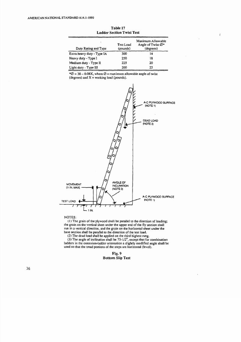
7/21/2019 Ansi a14.1 Ladders
http://slidepdf.com/reader/full/ansi-a141-ladders 41/81
AMERICAN NATIONAL STANDARD A14.1-1990
36
Table 17
Ladder Section Twist Test
Duty Rating and Type
Extra heavy duty - Type IA
Heavy duty -Type I
Medium duty - Type II
Light duty - Type III
Test Loadpounds)
300
250
225
200
Maximum AllowableAngle of Twist 0
degrees)
14
18
20
22
0 = 8 - O.08X, where 0 =maximum allowable angle of twistdegrees) and X = working load pounds).
MOVEMENT
( /. IN. MAX
NOTES
A-C PLYWOOD SURFACE(NOTE 1)
DEADLOAO(NOTE 2)
A-C PLYWOOD SURFACE(NOTE 1)
1 The grain of the plywood shall be parallel to the direction of loading;the grain on the vertical sheet under the upper end of the fly section shall
run in a vertical direction. and the grain on the horizontal sheet under thebase section shall be parallel to the direction of the test load_
2) The dead load shall be applied on [he third highest rung.3) The angle of inclination shall be 75-1/2°, except that for combination
ladders in the extension-ladder orientation a slightly modified angle shall beused so that the tread portions of the steps are horizontal level).
Fig. 9
Bottom Slip Test

7/21/2019 Ansi a14.1 Ladders
http://slidepdf.com/reader/full/ansi-a141-ladders 42/81
)
AMERICAN NATIONAL STANDARD A14. 1-1990
Table 18
Bottom Twist Test
Duty Raling and Type
Test Weight on 3rd
Highest Fly Rung(pounds)
Horizontal Pulling
Force(pounds)
Extra heavy dUly Type I
Heavy duty - Type I
Medium duty - Type II
Light duty· Type III
fixed. An initial preload of 600 inch-pounds, applied
in a clockwise direction, shall be used to establish a
reference for angular deflection, after which the ladder
shall be unloaded. A torque of 1200 inch-pounds shall
than be applied in accordance with one of the two
methods shown in Fig. 8. The torque shall be applied
first in a clockwise and then in a counterclockwise
direction. The angle of twist measured from thehorizontal position shall not be greater than the values
in Table 17. Attention shall be given to ensure that the
ladder is tightly clamped onto the test fixtures during
this test.
7.2.5 Bottom Slip Test. Note: This is a design
verification test. Single and extension ladders shall be
tested for skid resistance as shown in Fig. 9. The test
unit shall be a 16-foot extension ladder in the fully
extended position. The test surface shall be A·C
plywood, which shall be presanded using 320 fine
wet/dry sandpaper. The A side of the plywood shall
be placed in contact with the bottom of the ladder. The
surface that the top of the fly section rests against
shall also be A-C plywood, similarly treated.
A weight, in accordance with Table 18 shalI be
attached to the third highest fly rung. A horizontal
pulling force, in accordance with Table 18 statically
applied to the bottom of the ladder at I inch above the
test surface, shall not cause any noticeable movement
across the test surface.
7.2.6 Multisection Extending Force Test for
Extension Ladders. Note: This is a design verifica·
tion test. The test unit shall be a complete extension
ladder. The unit shall be set in a vertical position. at
the minimum working length of the ladder. The base
section may be braced or otherwise held to maintain
vertical alignment. A measured downward force shall
be applied to the rope if the ladder has a rope and
pulley system installed. The force shall be smoothly
applied to cause vertical extension of the fly section of
2 feet or more, at a rate of 1/2 to I foot per second.
For those ladders not equipped with rope and
pulley the measured force shall be applied vertically
300250
225
200
5050
50
50
to the bottom rung of the top section. The maximum
measured force that occurs during each pull shall be
recorded. Three test pulls shall be done for each
ladder, and the maximum forces shall be averaged for
the three pulls. This average maximum force shall not
exceed two times the weight of the ladder top section.
7.3 Tests for Stepladders, Platform Ladders.Trestle Ladders, Extension Trestle Ladders, and
Stepstools.
7.3.1 Compression Test. Note: This is a design
verification test. A load test of the entire ladder or
stepstool shall be made with the ladder in an open
position, as shown in Fig. 10. A unifonnly distrubuted
load, in accordance with Table 16. shall be applied for
a minimum period of I minute to the ladder top cap or
platform. Trestle ladders and the base section of exten·
sion trestle ladders shall be subjected to twice the test
loads in Table 16 by simultaneously applying the test
load to both sections of the ladder at the top or
via a loading block or plate across the top of the rails
when no top cap is used. For the extension trestle.
the load shall be applied via a loading block or plate
across the top of the rails of the extended section when
that section is extended a minimum of I foot above the
minimum working height. This test will also serve as u
design verification test of the locking mechanism. The
unit shall withstand the load without test failure.
7.3.2 Bucket Shelf Test for Stepladders. Note:
This is a design verification test. The bucket shelf shall
be constructed so as to support a distributed load of
100 pounds, applied to the shelf for a minimum of
I minute while the ladder is in an open position with
the spreaders locked. The bucket shelf shall withstand
the load without ultimate failure.
7.3.3 Front StabiJity Test for Stepladders,
Platform Ladders, Trestle Ladders, Extension
Trestle Ladders, and Step Stools; Note: This is a
design verification test. The ladder shall be set in the
open position on a level floor. A uniformly distributed
load. in accordance with Table 19. comprising lead
37

7/21/2019 Ansi a14.1 Ladders
http://slidepdf.com/reader/full/ansi-a141-ladders 43/81
38
COMPRESSlON TEST{TOP C P LO DING}
i in WOO LOADING
BLOCt
NOTE: This test is illustrated for a stepladder
Fig 10Compression Test

7/21/2019 Ansi a14.1 Ladders
http://slidepdf.com/reader/full/ansi-a141-ladders 44/81
)
)
AMERICAN NATIONAL STANDARD AI4.1-1990
Table 19
Stability Test Loads·
Front SideDistributed Pulling Pulling
Duty Rating and Type Loadt Force Force
Extra heavy duty - Type lA 200 25 20
Heavy duty - Type I 200 25 20
Medium duty - Type 200 25 20
Light duty - Type III 200 25 20
All quantities are in pounds.
tThis load is applied at the second highest step or platform.
SIDE PULLINGFOR E NOTE)
FRONT PULLINGFOR E NOTE)
200-lb UNIFORMLY
olSTR I BUTEOLOAD
SECOND HIGHESTSTEP
NOTES:
Rear Pulling Force Torsional
Stability
Platform Step Pulling
Ladders Ladders Force
35 45 30
35 45 30
35 45 25
35 45 20
1) The pulling force shall be applied at a maximum distance of 1/2 inch above the top of
the stepladder.2) This test is illustrated for a stepladder.
Fig. 11
Front, Side, and Rear Stability Tests
39

7/21/2019 Ansi a14.1 Ladders
http://slidepdf.com/reader/full/ansi-a141-ladders 45/81
AMERICAN NATIONAL STANDARD AI4.1-1990
weights or the equivalent to maximize the density of
the loading medium, shall be applied to the second
highest step, rung, or the platform the highest proper
standing level), as shown in Fig. 11. For an extension
trestle ladder, the load shall be applied to the second
highest extension-section rung.)
The ladder shall then be subjected to a horizontal
pulling force, in accordance with Table 19. applied atthe geometric center of the stepladder top cap, at a
distance of not more than 1/2 inch above its top
surface, towards the front of the ladder, as shown in
Fig. I I. The pulling force shall be applied to the top
horizontal guard rail member of platform ladders, and
to the apex of the base section of trestle and extension
trestle ladders. Step stools shall be loaded with the
distributed load on the top cap. and the pulling force
shall e applied to the top cap also. The test surface
shall be such as to ensure that the ladder does not slip
or slide during the test.
During this test, the minimum load that causes the
ladder to tip over shall not be less that the value shown
in Table 19. Ladders equipped with a bucket shelf shall
be tested with the bucket shelf in the in-use position.
7.3.4 Side Stability Test for Stepladders
Platform Ladders Trestle Ladders Extension
Trestle Ladders and Step Stools. Note: This is a
design verification test. The side stability of a ladder
shall be measured with the ladder set n an open posi
tion on a level floor. A uniformly distributed load, in
accordance with Table 19 comprising lead weights or
the equivalent to maximize the density of the loading
medium. shall be applied to the second highest step,
rung, or the platform, as shown in Fig. 11. For an
extension trestle ladder the load shall be applied to
the second highest extension-section rung.)
The ladder shall then be subjected to a horizontal
pu lling force, in accordance with Table 19, applied to
the side of the front rail, at the geometric center of the
stepladder top cap, at a distance of not more than 1/2
inch above its top surface, as shown in Fig. 11. The
pulling force shall e applied to the top horizontal
guard rail member of platform ladders and to the apex
of the base section of trestle and extension trestle lad
ders. Step stools shall be loaded with the distributed
load on the top cap, and the pUlling force shall be
applied to the top cap also. The test surface shall besuch as to ensure that the ladder does not slip or slide
during the test.
During this test, the minimum load that causes the
ladder to tip over shall not be less than the value
shown in Table 19. The test shall be run with the force
applied to both sides and the values shall be averaged
to obtain the minimum load. Ladders equipped with a
40
bucket shelf shall be tested with the bucket shelf in
the in-use position.
7.3.5 Rear Stability Test for Stepladders,
Platform Ladders Trestle Ladders Extension
Trestle Ladders and Step Stools. Note: This is a
design verification test. The rear stability of a ladder
shall be measured by placing the ladder in an open
position on a level floor. A uniformly distributed load,in accordance with Table 19, comprising lead weights
or the equivalent to maximize the density of the load
ing medium, shall be placed on the second highest
step, rung, or the platform the highest proper standing
level), as shown in Fig. II. For an extension trestle
ladder the load shall be applied to the second highest
extension-section rung.)
The ladder shall then be subjected to a horizontal
pulling force, in accordance with Table 19, applied to
the geometric center of the stepladder top cap, at a
distance of not more than 1/2 inch above its top sur
face, in a rearward direction, as shown in Fig. 11.
The pulling force shall e applied to the top horizontal
guard rail member of platfonn ladders and to the apex
of the base section of trestle and extension trestle
ladders, and to the top cap or combination ladders on
the top step when no cap is used. Step stools shall be
loaded with the distributed load on the top cap, and
the pulling force shall be applied to the top cap also.
The test surface shall be such as to ensure that the
ladder does not slip or slide during the test.
During this test, the minimum load that causes the
ladder to tip over shall not be less that the value shown
on Table 19. Ladders equipped with a bucket shelf
shall be tested with the bucket shelf in the in-use
position.
7.3.6 Torsional Stability Test for Stepladders,
Platform Ladders Trestle Ladders and Extension
Trestle Ladders. Note: This is a design verification
test. The test unit shall be placed on a level floor, in
the fully opened position, with the spreaders properly
set. A 200-pound distributed dead load, comprising
lead weights or the equivalent to maximize the density
of the loading medium, shall be applied to the ladder
top cap, platform, or top step when no top cap is used,
as shown in Fig. 12. A horizontal force, in accordance
with Table 19, directed to the rear of the ladder, shall
be applied to the ladder top cap at a distance of 18inches from the vertical centerline of the ladder, as
shown in Fig. 20. The force shall be maintained per
pedicular to the moment arm, with a tolerance of±IO°,
during the test. The test shall be conducted on a dry
unwaxed vinyl tile floor.
Relative movement in excess of 1 inch of the ladder
with respect to the floor, any damage or visible

7/21/2019 Ansi a14.1 Ladders
http://slidepdf.com/reader/full/ansi-a141-ladders 46/81
_._._ _.
)
CLAMPNOTE 2)
AMERICAN NATIONAL STANDARD AI4.1·1990
200 LB DEAD WEIGHT
9 ~ ± ~
~ T E S T L O DLEVEL TO BASE
TEST BAR
NOTE 1)
NOTES:
I ) The test bar is clamped to the top cap.
2) The clamp is used for the rail torsion and spreader tests in 7.3.6 and
7.3.9.
3) The test surface shall be dry unwaxed vinyl tile.
4) This test is illustrated for a stepladder.
Fig. 12Torsional Stability and Rail Torsion and Spreader Tests
41

7/21/2019 Ansi a14.1 Ladders
http://slidepdf.com/reader/full/ansi-a141-ladders 47/81
AMERIcANNAnONALS TANDARDA14.1-1990
42
Method for Blocking Test
a)
IOO-lbDISTRIBUTED _ 1 1 1_
LOAD
NOTES
BLOCKNOTE 2
INIMUM FOR E APPLIEDTO LIFT REAR FEET
NOTE 4)
Test Setup
b)
L T E R L/ / DISPLACEMENT
LATERALr \ TEST FOR E
I \ NOTE IFLOOR
I) The lateral force shall be applied using a force gage or the equivalent. The force shall be applied
parallel to the bonom of the front section. The lateral displacement of the rea r section shall be measured
parallel to the direction the lateral force is applied.
(2) Blocks fIxed to the test surface are used to resist rail rotation.
(3) This test is illustrated for a stepladder.
(4) The ven icall ifting force shall be applied by a member bearing against the rear center of the ladder
top cap, and shall be attached to a 5/16 inch minimum diameter rope at least 3 feet long with the rope
secured against motionin
any direction at leasl 3 feet above the ladder top.
Fig. 13
Racking Test

7/21/2019 Ansi a14.1 Ladders
http://slidepdf.com/reader/full/ansi-a141-ladders 48/81
J
AMERICAN NATIONAL STANDARD AI4.1 ICJtJO
Table 20
Maximum Allowable Racking Deflection
Detlectiont
Ladder
Size Type- and -IA Ladders Type-II Ladders
(feet) y 1.35 +.3.9 Y= 1.35 7.9
3 7.95 11.95
4 9.30 13.30
5 10.65 14.65
6 12.00 16.00
7 13.35 17.35
8 14.70 18.70
10 17.40 21.40
12 20.10 24.10
14 22.80
16 25.50
18 28.20
20 30.90
All deflections are measured in inches.
tY lateral racking deflection (inches) during a 6-pound pull;
= ladder size (feet).
SI E GUI ES
SUPP RT
Type-III Ladders
y L35X 7.9
11.95
13.30
14.65
16.00
24- ,ROP
H IGHT
NOTE: This test is for cantilever in only. It is performed with the ladder close d.
Fig. 14
Dynamic Drop Test
43
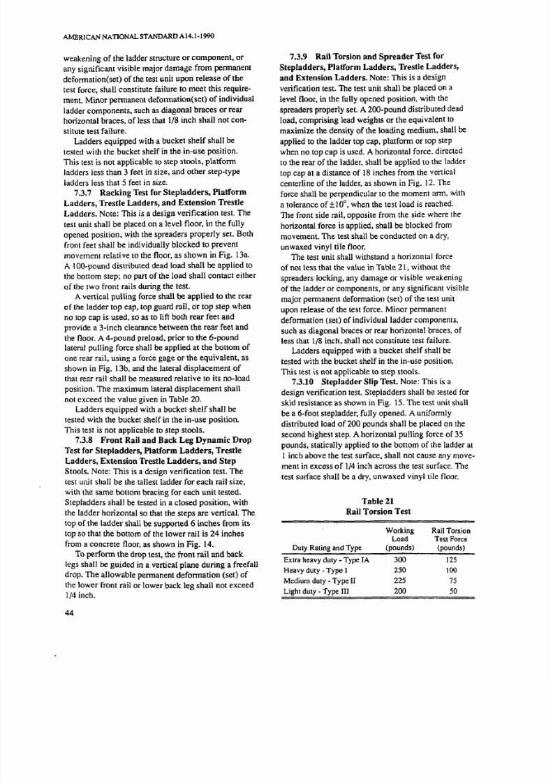
7/21/2019 Ansi a14.1 Ladders
http://slidepdf.com/reader/full/ansi-a141-ladders 49/81
AMERICAN NATJONALSTANDARD A14.1-1990
weakening of the ladder structure or component, or
any significant visible major damage from permanent
deformation set) of the test unit upon release of the
test force, shall constitute failure to meet this require
ment. Minor pennanent deformation set) of individual
ladder components. such as diagonal braces or rear
horizontal braces, of less that 1/8 inch shall not con
stitute test failure.Ladders equipped with a bucket shelf shall be
tested with the bucket shelf in the in-use position.
This test is not applicable to step stools. platfonn
ladders less than 3 feet in size. and other step-type
ladders less that 5 feet in size.
7.3.7 Racking Test for Stepladders , Platform
Ladders, Trestle Ladders, and Extension Trestle
Ladders. Note: This is a design verification test. The
test unit shall be placed on a level floor. in the fully
opened position. with the spreaders properly sel. Both
front feet shall be individually blocked to prevent
movement relative to the floor. as shown in Fig. 13a.
A IOO-pound distributed dead load shall be applied to
the bottom step; no part of the load shall contact either
of the two front rails during the test.
A vertical pulling force shall be applied to the rear
of the ladder top cap. top guard rail. or top step when
no top cap is used, so as to lift both rear feet and
provide a 3-inch clearance between the rear feet and
the floor. 4-pound preload. prior to the 6-pound
lateral pulling force shall be applied at the bottom of
one rear rail. using a force gage or the equivalent. as
shown in Fig. 13b, and the lateral displacement of
that rear rail shall be measured relative to its no-load
position. The maximum lateral displacement shall
not exceed the value given in Table 20.
Ladders equipped with a bucket shelf shall be
tested with the bucket shelf in the in-use position.
This test is not applicable to step stools.
7.3.8 ront Rail and Back Leg Dynamic Drop
Test for Stepladders, Platform Ladders, Trestle
Ladders, Extension Trestle Ladders, and Step
Stools. Note: This is a design verification test. The
test unit shall be the tallest ladder for each rail size,
with the same bottom bracing for each unit tested.
Stepladders shall be tested in a closed position, with
the ladder horizontal so that the steps are vertical. The
top of the ladder shallbe
supported 6 inches from itstop so that the bottom of the lower rail is 24 inches
from a concrete floor. as shown in Fig. 14.
To perfonn the drop test, the front rail and back
legs shall be guided in a vertical plane during a freefall
drop. The allowable permanent deformation set) of
the lower front rail or lower back leg shall not exceed
1/4 inch.
44
7.3.9 Rail Torsion and Spreader Test for
Stepladders, Platform Ladders. Trestle Ladders,
and Extension Ladders. Note: This is a design
verification test. The test unit shall be placed on a
level floor. in the fully opened position, with the
spreaders properly set. A 200-pound distributed dead
load. comprising lead weights or the equivalent to
maximize the density of the loading medium. shall beapplied to the ladder top cap. platfonn or top step
when no top cap is used. horizontal f.:>rce. directed
to the rear of the ladder, shall be applied to the ladder
lOp cap at a distance of 18 inches from the vertical
centerline of the ladder, as shown in Fig. 12. The
force shall be perpendicular to the moment arm, with
a tolerance of± 0°. when the test load is reached.
The front side rail, opposite from the side where the
horizontal force is applied. shall be blocked from
movement. The test shall be conducted on a dry,
un waxed vinyl tile floor.
The test unit shall withstand a horizontal force
of not less that the value in Table 21, without the
spreaders locking. any damage or visible weakening
of the ladder or components, or any significant visible
major permanent deformation set) of the test unit
upon release of the test force. Minor permanent
deformation set) of individual ladder components,
such as diagonal braces or rear horizontal braces, of
less that 1/8 inch, shall nOl constitute test failure.
Ladders equipped with a bucket shelf shall be
tested with the bucket shelf in the in-use position.
This lest is not applicable to step stools.
7.3.10 Stepladder Slip Test. Note: This is a
design verification test. Stepladders shall be tested forskid resistance as shown in Fig. 15. The test unit shall
be a 6-foot stepladder, fully opened. uniformly
distributed load of 200 pounds shall be placed on Ihe
second highest step. A horizontal pulling force of 35
pounds, statically applied to the bottom of the ladder at
1 inch above the test surface, shall not cause any move
ment in excess of 1/4 inch across the test surface. The
test surface shall be a dry, unwaxed vinyl tile floor.
Table 21
Rail Torsion Test
Duty Rating and Type
Extra heavy duty - Type IA
Heavy duty - Type I
Medium duty - Type II
Light dUly - Type III
WorkingLoad
pounds)
300
250
225
2
Rail TorsionTest Force
pounds)
125
tOO
75
50

7/21/2019 Ansi a14.1 Ladders
http://slidepdf.com/reader/full/ansi-a141-ladders 50/81
AMERICAN NA TIONAL STANDARD A 14.1·1990
NOTE: The 200-pound distributed load shall be placed on the second highest step.
Fig. IS
Stepladder Slip Test
7.4 Labeling Tests
7.4.1 General. The following procedures are
designed to evaluate the suitability of primary hazard
(danger and caUl ion), safety use instruction (safety
first), and product data infonnation (notice) labels for
application to ladders, and the perfonnance of printed
labels applied to surfaces representative of those
employed in the intended application.
NOTE: See Seclion 9, Labeling/Marking Requirements, for
layout detail. color, and format of labels.
Unless otherwise specified. the l abels are applied
to the appropriate surfaces and conditioned for 24
hours at 73 0 F(±o F and 50 ±5 humidi ty (±5 ).
Satisfactory results are needed on three samples for
each test to fulfull the requirements.
t is not intented that the tesls shall be conducted on
a progressive basis on one set of test samples. After
each environmental test, the samples should be condi
tioned at 73°F (±5°F and 50 releat ive humidity ±5
for 24 hours before subsequent test are conducted.
7.4.2 Tests
NOTE: These tests are all design verification tests and
should be performed on a standard substrates rather than on
actual ladders. The substrates shall be southem yellow pine
or the manufaclUrer's standard rail material with nominal
th ickness of 3/4 inch.
Labels shall be mounted using a 4-1/2-pound
weighted roller and then cured for 24 hours before
being subjected to test.
7.4.2.1 Adhesion Test. The test shall be
conducted on a new label that has not been subject
to other tests in 7.4.2, according to ASTM 0903-49
( 1988), Test for Pee l or Stripping Strength of
Adhesive Bonds.3 A minimum force of 30 ounces
shall be required to remove the label.
7.4.2.2 Scratch Resistance Test. The label
shall resist defacement or removal when a flat metal
blade l/32-inch thick. held at a right angle to the test
>Available from the American So ciety for Testing and Materials.
1916 Race Street. Philadelphia. Pa. 19103.
45

7/21/2019 Ansi a14.1 Ladders
http://slidepdf.com/reader/full/ansi-a141-ladders 51/81
AMERICAN NATIONAL STANDARD AI4.1·1990
panel, is scraped across it. This rest shall be run
on labels before and immediately afrer the wate r
immersion test.
7.4.2.3 Water Immersion Test. Applied
labels shall be immersed in water, label side down,
with the water level a minimum of 1/8 inch above the
label, for 48 hours at 7 5 ~ No significant change shall
occur in the legibility of the labels or in their adhesionto the ladder surface (as evidence by delamination or
curling) following the test.
7.4.2.4 Oven Aging Test. Applied labels shall
be placed in an oven maintained at a temperature of
158°F (700 q for 240 hours. No significant change
shall occur in the legibility of the labels or in their
adhesion to the ladder surface (as evidence by
delamination or curling) following the test.
8 Selection, Care, and Use
8.1 General
8.1.1 For maximum serviceability and safety and
to eliminate unnecessary damage to equipment, good
safe practices in the use and care of ladder equipment
shall be employed by the users. The guidel ines dis
cussed in this section constitute the most appropriatte
and proper procedures for the car and use of ladders.
8.1.2 A comparison of studies within A 14 juris
diction, by government bodies, by other researcher,
and in the ILO 4 Publication CIS-12, Ladders ,
indicates a close correlation between major accident
causes and the failure to follow guidelines like those
provided in this section.8.1.3 The major causes of falls from self
supponed portable ladders are lack of stability and
sliding. Major causes of falls from non-self-supporting
portal be ladders are lateral sliding at the top support,
and human Slip Table 22 provides a summary of
significant accident causes.
8.1.4 Proper selection of a ladder is essential
for ensuring safety and reducting the potential for
accidents.
8.1.5 Proper use of a ladder will contribute
significantly to safety. Factors contributing to falls
include haste, sudden movement, lack of attention
during use, ladder condition (worn or damaged), user s
age or physical condition, or both, and the user s foot
wear. The likelihood of falls is not increased by the
user s excessive weight or size. However, improper
4Available from the Intemation Occupational Safety and Health
Information Centre. International Labour Office. CH 1211 Geneva
22. Switzerland.
46
climbing posture creating user clumsiness on the
ladder may cause falls.
8.1.6 The safe useful life of the ladder is depend
ent upon its proper in-service care. While ladders are
designed for extended service, it is necessary to
provide periodic in-service care and maintenance to
ensure their continued safe use. Ladders are not
designed or intended to possess an infinite safe usefullife.
8.1.7 The information provided in the balance
of this section principally addresses stepladders and
extension ladders. The principles, however, are
applicable to all self-supporting and non-self-support
ing ponable ladders.
8.2 Selection
8.2.1 Ladder Selection. Portable ladders are
designed f T one-man use to meet the requirements of
the man, the task, and the environment. This section
covers the factors involved in making the proper lad
der selection. Product information data necessary forproper ladder selection are found on the ladder rail.
8.2.1.1 Duty Rating. Ladders have been
designed in four duty classifications:
Working Load
Duty Rating Ladder Type pounds)
Extra heavy duty. I 3
Heavy duty 250
Medium dUly II 225
Light duty lI 200
8.2.1.2 Loading and Service. Users shall give
consideration to the length required, the working load,
the duty rating, and frequency of use to which the
ladder will be subjected. Users shall not overload a
ladder.
The following criteria shall be used when purchas
ing or using a ladder:
I) Extra Heavy Duty For users requiring a 300-
pound working load or duty rating, such as industry,
utilities, contractors, and the like.
2) Heavy Duty For users requiring a 250·pound
working load or duty rating, such as industry, utilities,
contractors, and the like.
3) Medium Duty For users requiring a 225-poundworking load or duty rating, such a painters, offices,
light maintenance, and the like.
4) Light Duty For users requiring no more than
a 200-pound working load or duty rating, such as
general household use. Light-duty ladders shall
not be used with ladder jacks or scaffolds planks,
or both.

7/21/2019 Ansi a14.1 Ladders
http://slidepdf.com/reader/full/ansi-a141-ladders 52/81
AMERICAN NATIONAL STANDARD .l, \4.1·\"'11 I
) Table 22
ummary of Significant Accident Causes
Possible Factors Involved in Accidenr
Ladder Cause of Base SuppOrt L ~ d k r S< It:Ctillll
D c s i ~ n Accident or Surface ToeSuEPort S e t - U ~ User Location and Condition
Self- Stability Soft NO Unlocked Above "highest Too short (size)
supporting Uneven applicable spreaders standing level" Incorrect lacldt:r
(stepladder) Unstable surface One or more feet label tYP< ( A.I.11.
Slipper surface unsupported Reaching out toO or I II
Differences in lJsed unstable far. panicularly Incorrect s \ V l ~flmlness of or insufficient lalemIIv ladder (for ex·
surface supports Climbing onto ladder :lmplt:. platform
Slope of surface Ladder not close from above or single versusenough to work Handling heavy loads stepladdcr)
location or unstable objects Use of improperUser's physical Applying side load eljuipment (forcondition example. ladder
versus scaffold)
Sliding Uneven surface Not U ed as a non- Reaching out too far Use of improperLow friction applicable self-supporting Stepping off ladder eljuipment (for
Unstable surface ladder Applying side load example. ladderIce snow or Ladder not close versus scaffold)
wet surface enough to work Removal or de-Slippery surface location terioration of
Worn. missing or slip-resistantcontaminated ladder feetfeet
Non-self- Human slip Not applicable Not Pitch (angle) too Descending Dirty. oily. or i<:y
supponing applicable steep (especially step surfuces(extension with flat rungs) Use of improperand User's physical equipment (lor
)single) condition or example, ladder
shoes versus ~ c a f f o k lLateral Uneven surface Uneven Not tied off Getting on or off Too short or toosliding Differences in surface Not held at base ladder to roof long (size)(left or flmlness of Slippery Inadequate or Reaching OUltoo Not extended furright) at surface surface excessive ex- far laterally enough (tootop sup- Unstable surface Unstable tension above Applying side load steep)port surface' top support Use of improper
(pole. (ree, Ladder not close equipment (fmcomer of enough to work example. ladderbuilding. location versus scaffold)and the like) Pitch (angle) 00
\ce. snow. steepor wet Feet unsupportedsurface or unstable
Insufficient Extension locks
toe sUEE2rt nO e n ~ a g e dOutward Unstable surface Overexten- Used unstable or Above "highest Wrong 1'01)( orsliding at Low friction sian above insufficient standing level" skid-resistantlower base Loose surface top support supports label bearing surfacesupport Ice, snow, or wet Pitch (angle) Sliding tendency Too long (size) or
surface 100 flat increases above extended too farSlippery surface· Ladder not fOOled midpoint of Use of impropa
Ladder not tied ladder working equipment (for
off or blocked length exampk. ladderWorn, missing or Careless climbing versus scu ffold)slippery feet onto or off of
Improper selec- ladder (from aria·
tion of feet or roof. and the like)skid-resistant Applying side loadbearing surfaces
Extension locksengaged
,
47

7/21/2019 Ansi a14.1 Ladders
http://slidepdf.com/reader/full/ansi-a141-ladders 53/81
MERIC NN TION L STANDARD A 14.1-1990
Table 23
Ladder Size, Working Length and Height*
Extension Maximum
Ladder Size Working Length
16 13
20 1724 21
28 25
32 29
36 33
40 36
All quantities are in feet.
8.2.1.3 Proper Size
8.2.1.3.1 Extension Ladders. Selection of
proper extension-ladder size requires knowledge of the
vertical height or elevation to the top support point.
Where the top support is a roof eave, addit ional work
ing length is needed to permit the required 1- to 3-foot
extension beyond this point. The highest standing level
shall also be considered, although the actual dimension
will change as the ladder is extended. The nominal
relationships among size, working length, and height
to the top support point are given in Table 23.
8.2.1.3.2 Stepladders. The highest standing
level is constant for a specific stepladder. Typical
relationships are as follows:
Stepladder Size
feet)
4
5
6
7
8
1
Recommended ighest
Standing Level
I foot, I 1 inches
2 feet. 10 inches - 2 feet. II inches
3 feet, IO inches
4 feet. 9 inches - 4 feet, 10 inches
5 feet, 9 inches - 5 feet 10 inches
7 feet. 8 inches - 7 feet, 9 inches
The maximum work height is then establ ished by
adding the user s height and safe reach to the highest
standing level dimension.
8.2.1.3.3 User On-Ladder Location. There
are situations in which the use of a particular size
ladder creates a gap in the height that can be reachedby the user. For example, extension ladders of 28-fool
size and longer cannot be used to work on a wall
below a certain height because the user would be too
far out from the wall. Usually the lower portion of the
wall can be reached from the ground, which means up
to a height of about 7 feet. When this 28-foot exten-
48
Height to Roo f Eave
Height 10 Top with I· 1 3-Fool
Support on Wall Extension
To 12-1/2 9-1/2-11-1/2
12-1/2-16-1/2 13-1/2-15-1/216-1/2-20 17-19
20-24 21-23
24-28 25-27
28-32 29-31
32-35 32-34
sion ladder is closed to 14 feet, working on a wall
below IO feet becomes a problem
These conditions create a gap between 7 and 1
feet in height where another ladder selection is recom
mended. To work in this zone, a shorter non-self
supporting ladder or a self-supporting ladder such
as a stepladder should be considered.
8.2.1.3.4 Work Site Restrictions on .
Working Length. In cases where the work site
imposes a height restriction on the non-self-supporting
ladder s working length, the user may find that longer
ladders are not capable of erection at the proper angle
of inclination of75-1/2°. To safeguard against bottom
Sliding, select a shorter extension ladder or a single
ladder.
8.2.2 In choosing between a self-supporting anda non-self-supporting ladder, an important factor to
consider is the bottom and top support conditions. A
stepladder requires level support for four rails. If such
support is lacking or is not convenient. and if a top
support is available, an extension ladder might be a
better choice. In addition, the top support allows the
opportunity to secure or tie off the top to increase
stability.
8.2.3 Manufacturers do design and offer certain
ladders intended for use by more than one man. These
products shall be so identified on their labels and
markings.
8.3 Rules for Ladder Use
8.3.1 Intended Use. Ladder use shall be restricted
to the purpose for which the ladder is designed.
8.3.1.1 Ladders shall not be climbed by more
than one person at a time unless designed to support
more than one person.

7/21/2019 Ansi a14.1 Ladders
http://slidepdf.com/reader/full/ansi-a141-ladders 54/81
)
8.3.1.2 Self-supporting ladders shall not be
used as single ladders or in the partially closed posi
tion.
8.3.1.3 Unless specifically designed for a
cantilever operation, a non-self-supporting ladder shall
not be used to climb above the top support point.
8.3.1.4 Combination ladders, when used as
self-supporting stairway ladders shall not be climbed
on their back sections.
8.3.1.5 ladder jack system shall not be used
by more than two persons (see 8.3.19).
8.3.2 Climbing and Working Locations. The
user shall climb or work with the body near the middle
of the step or rung. The user shall not step or stand
higher than the step or rung indicated on the label
marking the highest standing level of a ladder. The
user shall not step or stand on:
I) A ladder top cap and the top step of a step or
trestle ladder, or the pail shelf of a self-supporting
ladder.
NOTE: This restriction is nOI applicable to lOp steps located18 inches under the top cap.
2) The rear braces of a self-supporting ladder,
unless these are designed and recommended for that
purpose by the manufacturer.
(3) The top step of the extension section of an
extension trestle ladder.4) The top cap or top step of a combination ladder
when it is used as a self supporting ladder.
8.3.3 Angle of Inclination . Portable non-self
supporting ladders should be erected at a pitch of
75-1/2° from the horizontal for optimum resistanceto sliding. strength of the ladder. and balance of the
climber. A simple rule for setting up a ladder at the
proper angle is to place the base a distance from the
wall or upper support equal to one-quarter the effec
tive working length of the ladder (the quarter length
rule ). Effective working length is the distance along
the side rails from the bottom to the support point of
the upper portion of the ladder. Combination ladders
should be erected so that the step surfaces are in a
horizontal plane.
8.3.4 Footing Suppor t. The ladder base shall be
placed with a secure footing on a finn. level support
surface. Ladder levelers may be used to achieve equalrail support on uneven surfaces. Devices such as
shoes, spurs, spikes. combinations thereof, or similar
devices of substantial design should be installed where
required for slip resistance and bearing area. Where
ladders with no safety shoes. spurs, spikes. or similar
devices are used, a foot ladder board or similar device
may be employed. Ladders shall not be used on ice.
AMERICAN NATIONAL STANDARD A 14.)·)990
snow. or slippery surfaces unless suitable means to
prevent slipping are employed. Ladders shall not be
placed on boxes, barrels. or other unstable bases to
obtain additional height.
8.3.5 Top Support. The top ofa non-self-support
ing ladder shall be placed with the two rails supported
equally unless it is equipped with a single support
attachment. Such an attachment shOUld be substantial
and large enough to support the ladder under load. It
should be used when the ladder top support is a pole.
light standard. building comer. or in tree-type opem
lions (pruning, fruit picking. and the like). When it is
necessary to support the top of a ladder at a window
opening. a device should be attached across Ihe back
of the ladder. extending across the window, to provide
fU l support against the building walls or window
frames.
8.3.6 Side Loading. Portable ladders are not
designed for excessive side loading, and such abuse of
the ladder shall be avoided. The ladder shall be kept
close to the work. The user shall not overreach, but
shall descend and relocate the ladder instead. When
using a ladder. the user shall never push or pull unless
the ladder is properly secured.
8.3.7 Climbing Ladder s. When ascending or
descending the ladder. the user shall face the ladder
and maintain a firm hold on the ladder. The user shall
not climb onto a ladder from the side, from one ladder
to another, or front a swing-stage to a ladder. unless
the ladder is secured against sideways motion or had
been tied to the slructure. The user shall not climb a
broken or bent ladder or a ladder that does not comply
with 8.4.1.8.3.8 Elect rical Hazards . Users are cautioned to
take proper safelY measures when ladders are used in
areas containing electrical circuits. These precautions
should prevent any contact or possible contact with an
energized. uninsulated circuit or conductor in order to
avoid electrical shock or short circuit. Metal ladders
and wood ladders with side-rail metal reinforcement
wires shall not be used where they would come in
contact with exposed energized electric wires.
All ladders should be kept away from electric
power lines unless they are specifically designed for
that application. Ordinary precautions should be
employed as would be taken when using any tool thatmay become a conductor of electricity. Users are
cautioned to be particularly careful when manipulating
any ladder around an overhead electrical power line.
8.3.9 Improper Use. A ladder shall not be used
as a brace. skid, lever. uy or gin pole. gangway. plat
form. scaffold plank, material hoist, or for any other
use for which it was not intended, unless such use is
49

7/21/2019 Ansi a14.1 Ladders
http://slidepdf.com/reader/full/ansi-a141-ladders 55/81
AMERICAN NATIONAL STANDARD A14.1·1990
specifically recommended by the manufacturer. Lad
ders shall not be erected on scaffolds to gain additional
height, unless specifically designed for that application.
8.3.10 Access to Roof. When single-section or
extension ladders are used to gain access to a roof, the
top of the ladder shall extend at least foot and no
more than 3 feet above the point of suppon at eaves,
gutter or roof line. The ladder should be tied down to
prevent slipping before the user ascends onlo the roof.
The user shall take care when ascending from the lad
der to the roof or descending from the roof to the lad
der to avoid tipping the ladder over sideways or
causing the ladder base to slide.
8.3.11 Fastening Together. Ladders and ladder
sections, unless so designed, shall not e tied or
fastened together to provide a longer length. Ladders
and ladder sections shall not have their length
increased by other means, unless specifically
designed for the means employed.
8.3.12 Doorways. Ladders shall not be placed
in front of doors opening toward the ladder unlessthe door is blocked open, locked, or guarded.
8.3.13 Setup and Adjusbnent of Ladders
8.3.13.1 Extension Ladders Adjustment of
extension ladders shall only be made by the user when
standing at the base of the ladder so the user may
observe when the locks are properly engaged. The user
shall check that the rope is tracking correctly in the
pulley. Adjustment of extension ladders from the top
of the ladder (or any level ov r the locking device) is
a dangerous practice and shall not be attempted.
Adjustments shall not be made while anyone is
standing on the ladder. The user shall ensure that both
upper and lower ladder support points are contactingfirm support surfaces. Extension trestle ladders and
combination ladders used in non-self-supporting posi
lions require that the same procedures be observed.
8.3.13.2 Stepladders The user shall ensure
that the stepladder is fully opened, with spreaders
locked and all feet contacting a firm level support
surface.
8.3.14 Erection of Extension Ladders Exten
sion ladders shall always be erected so that the top
section (fly sectiori) is above and resting on the bottom
section (base section) with the rung locks engaged.
The top section may e located in front of or behind
the bottom seclion. depending upon the design. The
ladder shall never be used in a reverse position where
the top end of the fly section becomes the lower end
of the ladder, and the lower end of the base section
becomes the upper end of the ladder. Where extension
ladders have been previously used as single ladders,
care should be exercised to ensure that the sections are
50
properly reassembled and that the interlocking guides
or brackets are properly engaged between the sections
before further use.
8 3 15 Relocating Ladders. A ladder shall not be
relocated while anyone is on it.
8.3.16 Bracing of Stepladders. The bracing on
the rear rails of stepladders is designed solely for
increasing stability and not for climbing. This does
nol apply to stepladders provided with steps for
climbing on both front and rear sections.
8.3.17 Use of IndividuaJ Sections of Sectional
Ladders and Sections of Extension Trestle Ladders.
Middle and top sections of sectional or window
cleaners ladders and extension sections of extension
trestle ladders should not be used for bottom sections.
8.3.18 Hooks When service conditions warrant.
hooks may be attached at or near the top of ponable
ladders to give added security. (Such hooks are used
for upper support in cable strand or rooftng applica
tions.)
8.3.19 Ladder lacks Only ex.tra-heavy-duty(type-IA) and heavy-duty (type-I) ladders shall be used
in conjunction with ladder jacks and stages or planks.
Light-duty (type-llI) and medium-duty (type-II)
ladders shall never be used with ladder jacks. For
additional information on ladder jack systems, see
American National Standard Safety Requirements for
Scaffolding, ANSI A 10.8-1988.
8.3.20 Ladders Designed for Special Uses.
Certain ladders are designed specifically as two-man
working load products. Included in this group are
trestle ladders, extension trestle ladders, and double
stepladders.
8.3.21 High Static Electrical Fields. Metalladders or other ladders specifically designed to permit
grounding or dissipation of static electricity should be
used around high static elecnical fields to assisting in
preventing shocks to the user.
8.4 Care
8.4.1 Inspection. A thorough ladder inspection
shall be made when the ladder is originally purchased,
received. and put into service. The ladder shall
inspected periodically, preferably before each use.
Working parts and runglstep-to-side-rail connections
shall e checked. Where structural damage or other
hazardous defect is found, the ladder shall e takenout of service and either discarded or repaired by a
competent mechanic.
8.4.1.1 Tipp ing Over, and Oth er Impact
Damage. The ladder shall be i n ~ p e t e d for cracks and
splits on side rails and rungs and steps. All rungl
step-to-side-rail connections shall be checked, as
7/21/2019 Ansi a14.1 Ladders
http://slidepdf.com/reader/full/ansi-a141-ladders 56/81
~ ) well as hardware connections, rivets (for shear). and
all other components.
8.4.1.2 Exposure to Fire. If ladders are
exposed to excessive heat, as in the case of fire, their
strength may be reduced. After such exposure, the
ladder shall be inspected visually for damage and
tested for deflection and strength characteristics.
More infonnation is provided in Section 7. In
doubtful cases, refer to the manufacturer.
8.4.1.3 Corrosive Substances. When ladders
are to be subjected to certain acids or alkali materials,
which may be chemically corrosive and significantly
reduce the working load of the ladder, consult the
manufacturer or a qualified person prior to such
exposure.
8.4.1.4 Oil and Grease. Ladders should be
free of oil, grease, or slippery materials on climbing
or gripping surfaces.
8.4.1.5 Ropes and Pulleys. Ropes, cables,
and pulleys should be inspected frequently, checked to
ensure that they operate properly, and replaced if they
are worn or defective.
8.4.2 Damaged Ladders . Broken Or bent ladders
shall e marked and taken out of service until they are
repaired by a competent mechanic or destroyed in
such a manner as to render [hem useless. The user
shall not attempt to repair a defective side rail.8.4.3 Proper Handling. Ladders, like any tool,
must be handled with care and not be subjected to
dropping, jarring, or misuse. They are designed for the
purpose intended. Therefore, any variation from this
purpose constitutes a mishandling of the equipment.
8.4.4 Transporting. Ladders transported on road,street, and highway motor vehicles shall be properly
supported. Overhang of the ladders beyond supporting
points should be limited. Supporting points should be
of a material such as wood or rubber-covered iron
pipe, to minimize chafing and the effects of road
shock. Securing the ladder to each support point will
greatly reduce damage due to road shock.
8.4.4.1 Truck Racks. Ladders shall be secured
to a truck rack in a manner that will avoid chafing
from relative horizontal and vertical motion. The
ladder feet when present, should be secured from
pivoting about the ladder while the vehicle is in
motion. The ladder truck rack shall be designed to
positively secure the ladder into a fixed position, and
the rack should be designed to fit the particular ladder
being fixed to the truck. f these requirements are not
satisfied, excessive wear of the ladder will occur,
which will cause premature deterioration of the ladder
and reduce its service life. Improperly designed and
used truck racks may damage side rails. steps or rungs,
AMERICAN NATIONAL STANDARD A14.1·1990
feet, and other ladder parts owing 10 vehicle vibration
and road shock.
8.4.5 Storage. Ladders should be stored in or on
racks designed to protect the ladder when it is not in
use. These racks should have sufficient supporting
points to avoid sagging. Material shall not be placed
on the ladder while it is in storage. Untreated wooden
ladders shall not be exposed to the elements and
should not be stored in damp places since such storage
will appreciably shorten their useful life.
8 4.6 Maintenance. Proper ladder maintenance
ensures the safe condition of the ladder. Hardware.
fittings, and accessories should be checked frequently
and kept in proper working condition. All pivotable
connections and the rung-lock cam surfaces should
be lubricated frequently. All bolts and rivets shall be
in place and secure before using a ladder. and no
ladder should be used if any bolts or rivets are
missing or if the joints between the steps (or rungs)
and the side rails are not tight.
8.4.6.1 Ladders with safety shoes or padded
feet which are excessively worn shall be taken out of
service until repaired.
8.4.6.2 Wood ladder tie-rods shall be tightened
as required.
8.4.6.3 Ladders may be coated with .trans
parent, nonconductive finish such as varnish. shellac.
or a clear preservative. Ladders shall not be coated
with any opaque covering except for a minimum
amount needed for identification or warning, and then
only on one face of the side rails.
8.4.7 Electrical Insulating Qualities . To ensure
the retention of the original electrical insulating characteristics, the ladder. when it is designed for use around
electrical circuits, shall he maintained in a clean condi
tion. All surface build-up of dirt, dust, grease, grime.
carbonaceous, and other conductive materials shall be
removed. The presence of such materials may provide
a ready path for electrical currents to trave over the
surface of the ladder and potentially endanger the user.
9. Labeling/Marking Requirements
9.1 Primary Hazard Danger and Caution
Markings
9.1.1 General
9.1.1.1 Primary hazard "DANGER" and
"CAUTION" markings shall confonn to the general
design principles, and where labels are used, to the
design and color principles of these requirements as
provided in Appendix A for the types and kinds of
ladders in the standard.
5

7/21/2019 Ansi a14.1 Ladders
http://slidepdf.com/reader/full/ansi-a141-ladders 57/81
AMERICAN NATIONAL STANDARD A14.1·1990
9.1.1.2 All markings shall be legible and
readily visible.
9.1.1.3 The preferred locations of the mark·
ings especially danger and caution markings,
should be approximately 4·1/2 feet to 6 feet from
the bottom of the ladder on the outside of the rails
(climber facing the ladder) with the ladder in the use
position.9.1.1.4 For ladders less than 6 feet in length
markings should be located as high as possible and
as close to the top as possible.
9.1.1.5 Markings shall be positioned so that
other parts of the ladder shall not damage the
label/marking when the ladder is open, closed, or
extended.
9.1.1.6 The labels/markings n the appendices
shall be considered as illustrations only.
9.1.1.7 Modification of markings, within the
design or color principles, or both of these require·
ments including equivalent wording and symbols,
shall be permitted to accommodate material finishand construction features.
9.1.1.8 Marking no. 00 shall e placed on all
portable ladders on the upper most marking on the
outside of the right rail (climber facing the ladder).
9.1.2 Stepladders
9.1.2.1 Marking no. 1 shall meet the general
requirements of location and positioning to avoiddamage to the label/marking.
9.1.2.1.1 For ladders less than 6 feet in
length, markings shall be located as high as possible
and close to the top cap.
9.1.2.2 Marking no. 2 shall be located on thelOp cap of stepladders.
9.1.2.3 Marking no. 3 shall be located on the
first step below the top cap when this step is 18 inches
or less from the cop and may be omitted when the first
step is more than 18 inches from the top cap.
9.1.2.4 The placement of markings no. 2 and 3
shall be such as to ensure best viewing position and to
accommodate design, construction features. and
materials and finishes.
9.1.2.5 Marking no. 4 shall meet the general
requirements for all ladders.
9.1.3 Extension and Single Ladders
9.1.3.1 Markings no. 5 and 6 shall meet thegeneral requirements for location.
9.1.3.2 Marking no. 6 shall be used on all
extension ladders and single ladders construction ofwood with wire·reinforced rails.
9.1.3.3 Markings no. 7 and 8 may be used
together if so desired.
52
9.1.3.4 Marking no. 7 shall be placed, in lieu of
marking no. 8 on the inside of the right rail of the fly
section of extension ladders, with the arrow pointing to
the second or third rung, depending upon which rung
is 24 inches or more from the top of the top section,
either of which location shall be the highest standing
level.
9 1 3 5 Marking no. 8 shall be placed. in lieu of
marking no. 7 on the second rung from the top when
the second rung is 24 inches or more from the top of
the top section, or placed on the third rung from the
top when the second rung is less than 24 inches from
the top of the top section, either of which location shall
he the highest standing level.
9.1.3.6 Marking no. 9 shall be placed below
marking no. 4 on both extension and single ladders.
9.1.3.7 Marking no. 10 shall meet the general
requirements for all ladders including equivalent
wording in the text.
9.1.4 Step Stool9.1.4.1 Markings no. II and 12 shall conform
to the general requirements for all ladders.
9 1 S Trestle Ladder
9.1.5.1 Marking no. 13 shall confonn to the
general requirements for all ladders.
9 1 5 2 Marking no. 7 shall be placed on the
inside of the right rail of the trestle ladder with the
arrow of the label/marking pointing to the secondstep or rung.
9.1.5.3 Marking no. 8 shall be located on the
second step or rung from the top of the ladder.
9.1.5.4 Markings no. 7 and 8 may be used
together if so desired.
9.1.6 Extension Trestle Ladders
9.1.6.1 When the extension section in [he
trestle ladder is used marking no. 7 shall be used as
required for single ladders.
9.1.6.2 Marking no. 14 shall meet the general
requirements for all ladders.
NOTE: This does not include label/marking for separateex.tension see ex.tension/straight ladder - Marking no. 10)
9.1.7 Platform Ladder
9.1.7.1 Marking no. I shall meet the general
requirements of location and positioning to avoid
damage to the label/marking.
9.1.7.2 Marking no. 2 shall be located on thetop cap or highest cross member above the platfonn.
9.1.7.3 Marking no. 15 shall conform to the
general requirements for all ladders.
9.2 Product Data Information Markings
9.2.1 The product data information markings
in 9.2.2 shall appear on the outside lower left rail

7/21/2019 Ansi a14.1 Ladders
http://slidepdf.com/reader/full/ansi-a141-ladders 58/81
(climber facing the ladder). and. where possible.
approximately 4-1/2 to 6 feet from the bottom of the
ladder.
9.2.2 Information Required. The following
information shall be preceded by the word NOTICE
in boldface and preferably shall be n the following
sequence.
9.2.2.1 Ladder size
9.2.2.2 Type or duty rating
9.2.2.3 Maximim working length (if extension
ladder)
9.2.2.4 Highest standing level
9 2 ~ 2 S Total length of sections (if extension
ladder)
9.2.2.6 Model number or name
9.2.2.7 Manufacturer or distributor name (may
be logo)
9.2.2.8 Manufacturing plant if multiplant
organization) (may be coded)
AMERICAN NAT IONAL STANDARD A 14.1·1990
9.2.2.9 Month and year of manufacture
9.2.2.10 ANSI Standard compliance
9.2.2.11 Warranty, if offered (optional)
9.2.3 Preferred Presentation. Product data
information markings shall preferably be presented
as provided by the label/marking and instructions ill
Appendix B See Marking no. 16).
10. Revision of American National Standard sReferred to in This Document
When the American National Standards referred to in
this document are superseded by a revision approved
by the American National Standards Institute. Inc, the
revision shall apply.
53

7/21/2019 Ansi a14.1 Ladders
http://slidepdf.com/reader/full/ansi-a141-ladders 59/81
AMERICAN NATIONAL STANDARD AI4.1-1990
ppendixes(These Appendixes are not p n of American National Standard AI4.1-1990. but a re included forinfonnationpurposes only.)
Appendix A
NOTE: The following are the preferred design and color principles for the primary hazard DANGER . and
CAUTION labels/markings for the kinds of portable wood ladders cited in this standard. These labels/markingsare illustrations of typical labels/markings and are not actual recommended size The minimum recommended size
is 2 inches x 8 inches.
RE OVAL WITH
WHITE LETTERS
54
BLACK LETTERS ON
WHITE BACKGROUND
WHITE
BLACK
BACKGROUND
SAME COLOR NOT S AS OTHER DANGER
YELLOW LETTERS ON
V BACKGROUND
f i t i i i ~ j i j ~ i i i i l j i j j i i i i i i i i i l j i i ~ i l l
BLACK L IT RS ON
YELLOW BACKGROUND

7/21/2019 Ansi a14.1 Ladders
http://slidepdf.com/reader/full/ansi-a141-ladders 60/81
- -- -
AMERICAN NATIONAL STANDARDAI4.1-1990
Appendix B
NOTE: The following are the preferred design and color principles for SAFETY FIRST" (safet)' instructions) and
NOTICE (product data infonnation) labels/markings for the kinds of portable metal ladders cited in this standard.
These labels/markings are illustrations of typical labels/markings and are not actual recommended size. The mini
mum recommended size is 2 inches x 8 inches.
WHITE LETTERS
S FETYFIRST
BLUE BACKGROUND
NOTI EGREEN WHITE LEITERSBACKGROUND
GREEN OR BLACK LETTERS ONWHITE BACKGROUND BLUE OR BLACK LETTERS ON
Preferred Presentation o Product
Data Information Markings
The preferred presentation is not mandatory. but if it is used,it should be used in the panel sequence illustrated in Marking
No. 16. f necessary, elements may be rearranged. as multi
ple panels are used. However, any panel which includes thedata of pane no. I should be shown with the word
"NOTICE" as illustrated in Marking No. 16
The best method would be to present the notice
and three panels as one label or marking. This method would
mean the month and year date, for economic use of
preprinted labels, would have to be entered by ink stamp for
the one-label approach. Permanent inks should be sought-and are available - for such applications. In fact. if this in
formation is stamped or bumed, the rest of the marking can
be a label or similarly stamped or burned, as long as the one
label effect is maintained.
The three panels are also designed to be divided between
panels no. I and 2 and panels no. 2 and 3. The notice and
panel no. I should be presented as one unit either in a label
or other marking, since this product information is most criti
cal in selecting the right ladder. Such information provides
the necessary elements of a sound purchase that allows the
user to match his needs and requirements to the capabil itics
of the ladder.
Panel no. 2, if separated, may be stamped. burned,
embossed. or otherwise marked, including a label which
provides for ink stamping of month and year data. An effon
should be made to avoid the placement of OIher markings be
tween panels which are separated. In fact, the information in
panel no. 2 may be placed elsewhere if it is first placed as re
quired by 9.2. AddilOnally, the optional character of panel
no. 3 may eliminate its use or incorporate its information
in either panel no. I or 2.
Manufacturer's and distributor's name may be a logo.
Manufacturing plant (ifmulti·plant organization) may be
coded.
WHITE BACKGROUND
NOTICELadder Size
Type and/or DutyRaling
Maximum Working Length
III extension ladder)
HIghest Standing Level
Total length 1 SectionsIf extension Ladder)
Model Numberor Hame
Manulacturer or
Distributor Name
2Manulacturing Plant
II multi-plant organization)
Month and Yearal Manufacture
ANSIStandards Compliance
3Warranty
II Warranty Dnered
Marking No_ 16
Preferred Notice Presentation
55

7/21/2019 Ansi a14.1 Ladders
http://slidepdf.com/reader/full/ansi-a141-ladders 61/81
AMERICAN NATIONAL STANDARD AI4 1·1990
56
FAILURE TO READ AND FOLLOW
INSTRUCTIONS ON THIS LADDER
MAY RESULT IN INJURIES OR DEATH
FAILURE TO READ AND FOLLOW
INSTRUCTIONS ON THIS LADDER A
MAY RESULT IN INJURIES OR DEATH
FAILURE TO READ
AND FOLLOW
INSTRUCTIONS ON
THIS LADDER M YRESULT IN INJURIES
OR DEATH
Marking No 00
c

7/21/2019 Ansi a14.1 Ladders
http://slidepdf.com/reader/full/ansi-a141-ladders 62/81
[iB1jit UIKEEP BODY CENTERED
BETWEEN SIDE·RAilSDO NOT OVER·REACH~
AMERICAN NATIONAL STANDAR D A14.1 1990
DO NOT Marking No 2
ST NDBOVETHISSTEP
SET ALL FOUR FEETON FIRM LEVEL SURFACE.
WEAR SLIP RESISTANT SHOES
READ ADDITIONALINSTRUCTIONS ON LADDER
Marking No 1
I I
I Do Not Stand On OrI •E Ut; i bove This Step • OU CAN iI LOSE YOUR B L NCE i
_J
Marking No 3
57

7/21/2019 Ansi a14.1 Ladders
http://slidepdf.com/reader/full/ansi-a141-ladders 63/81
AMERICAN NAll0NAL STANDARD A14.1 l990
S FETYFIRST
STEPLADDER· FOR YOUR SAFETY
READ CAREFULLYPROPER SELECTION
1. Select ladder 01 proper ieI1g1It 10 reach worXing heigh1.
2 IMPORTANT: Ladders are designed to support one
person plus materials and tools not more th n theworking load on the notice sign on this ladder.
3 Select ladders within the following:
TYPE DUTY RATING WORKING LOADIA INDUSTRIAL·EXTRAHEAVY 300 Ibs
I INDUSTRIAL·HEAVY 250 100.
II COMMERCIAL MEDIUM 2251bs.
III HOUSEHOLD·UGHT 200 100.
INSPECTION1 Make sure ladder is fully open. spreaders secure. pall
shell in posnion.
2 Place on [[m level surlace wnh asecure footing. Do
not use on slippery surlaces. Do not pJace on boxes.
unstabte bases or on scaffolds to gain additional heiglllDo Not place in front oJ door opening toward ladder.
PROPER SET·UP1 DANGER METAL CONDUCTS ELECTRICrTY. Donot let ladders of any material oome in <Xl I1aCi wiUllive
eledJicaJ wires.
Z. Make sure ladder is lully open. spceadBlS secure. pail
shell in posnion.
3 Place on firm level surtace willi asecure kloling Do
not use on slippery surfaces. 00 not place an boxes,
unstable bases or scaHolds \0 gsin d d ~ n l height Donol place in nonl 01 door opening toward ladder
PROPER CLIMBING AND USE
1 DO NOT USE LADDERS ifyou tire easily. are subject10 lainling spells. are using medicine or alcohol orare physically impaired
2 To proteci children. do nOlleave ladder selo{Jp andunanended.
3 Face ladder when climbing up or down: keep body
cenlered belween side rails.
4 Maintain a irm grip. Use bolh hands In climbing.S Never climb ladder from Ihe side unless ladder is·secured againsl side·wise motiDn.
6 00 nDI over reach: move ladder wnen needed7 00 nOI"walk" or "jog" ladder when slanding on It
8 Do nOI sland. climb or sit on ladder lap pail Shelf.
braces or back seclion
9 Do nOI overload Ladders ale meanl tor one person.
00 nol use as brace. platform or plank.10 Keep ladder close 10 work; avoid pushing or
pulling ofllO Ihe side 01 ladders.
PROPER CARE AND STORAGEI. Siore ladder in safe and dry place.
2 Properly secure aod suppen ladder while in transit.
3 Naver store maleriais on ladder.4 Never paint awood li O:jet. treat at flequent inleNals
WAh wood preselVative or clear COaling.
S. Keep ladder clean and llee of aU foreign materials.
Marking No 4
58
[ttll it.HISET UP LADDER PROPERLYTO REDUCE SLIP ANDOVERLOAD HAZARDS.FOLLOW THESEINSTRUCTIONS.
SECURE
CD
®®@
PLACE TOES AGAINST SDnDMOF LADDER SIDERAILS
STAND ERECT
EXTEND ARMS STRAIGHT OUT
PALMS Df HANDS SHOULD TOUCHTOP OF RUNG AT SHOULDER £VEl
1 DO NOT OVER.KEEP BODY C n 'c u
BETWEEN SIDERAILS
2 EXTEND LADDER ONETO THREE FEET ABOVE
ROOF FOR ACCESS
3 READ ADDITIONALINSTRUCTIONSON LADDER
Marking No 5
I
r
HIS L DDER 1, CONDUCTS ,• ELECTRICITY·
Marking No 6
Do Not Stand On OrAbove This RungYOU CAN LOSEYOUR BALANCE
lMarking No 7
i
II
II

7/21/2019 Ansi a14.1 Ladders
http://slidepdf.com/reader/full/ansi-a141-ladders 64/81
------ -------
AMERICAN NATIONAL STANDARD AI4.H9 }()
Marking No.8
THIS L DDER SECTION
IS NOT DESIGNED
FOR SEP R TE USEMarking No.9
S
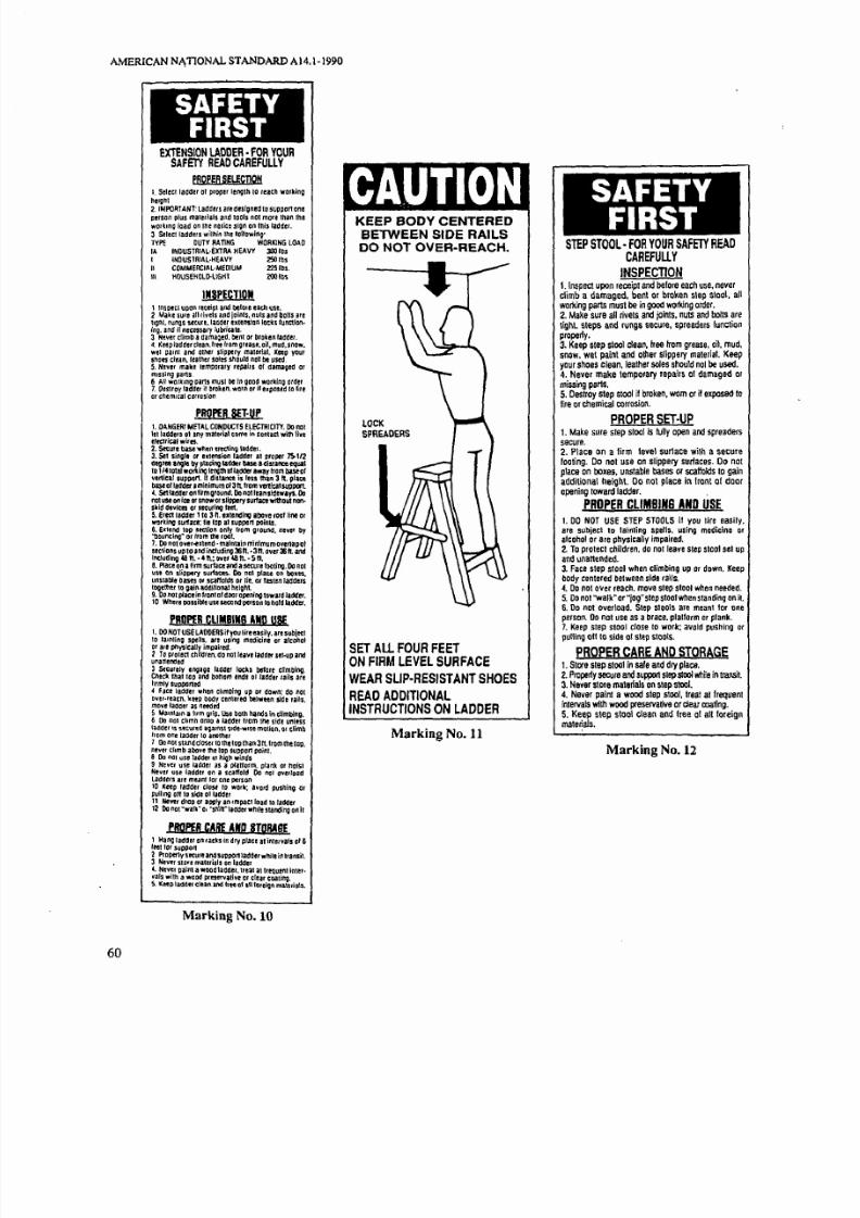
7/21/2019 Ansi a14.1 Ladders
http://slidepdf.com/reader/full/ansi-a141-ladders 65/81
AMERICAN NATIONAL STANDARD A14.1-1990
60
S FETYIRST
EXTENSION LADDER -FOR YOURSAFETY READ CAREFULLY
PROPER SELECDQN
I. SeleCi ladder 01 proper length 10 reach workinghelgnl2. IMPORTANT: Laaders areaeslgned to suppon oneperson plus malerlals and lools not more than theworkmo load on the nuice sign on Ihis laddel.3 Stlecllaaders within Ihe tonowlng'TYPI: DUTY RATING WORKING LOAD
IA INDUSTRIAL·EXTRA HEAVY 300 IDs
I INOUSTRIAL·HEAVY 250 IDsI COMMERCIAL·MEDIUM 225 IDs.III HOUS£HOLG-LIGHI l OO tb.
INSPECTIOII1 InSP tl ut\Q \ leceip\ and belore eath lSI :.2 Make sure all rivets and Joints. nuts a n ~ bOilS arelIon\. runos securt.laCldet ex.tensian locks 'unction.ing. and' if necessary lubricate.3 Never climb a damaged. bent or broken ladaer.4, Keeplad'der tlean.lree rom grease. oil, mUd. snow.wei oalnl and Olher slippery malerlal. Keep yourshOes clean. lealher soles should not be usea5, N ~ ' i e ' make lemgOrary repairs of damaged ormissing parts6 AI working pans must be in gOOd working order7. Destroy ladder it broken. worn or n exposed to lileor '''emlcal corroSion
PROPER SET·UPI DANGER METAL CONDUCTS ELECTRICITY. 00 nolftllaOders ot any material come in Contact with \iveeftctrical wires.2. Secure b;se when erecting \:addef.3. Sel single or e",ension ladder 01 proper ~ 1 2Goor l'1li10 by p l " ~ l ' I I I l a d l 1 t r base a Gist'''''' equal10 1I41D1oh,orl<ing length oIladder away ~ o m bUeorvenieal ,uplIOn. II distance is less lIIan 3 placeDase ol'aaa., aminimum 01 311 Irom YeII/calsupPOII.4. SetI.dderon lirm ;round. 00 nollnnsid.ways. 00not use on ice or snow or slippery u ~ a c t wiIIlOUI non·skid devices .r se(urin; leel.S Erect ladder 110 3 ~ , ••"ndin; abOve roolliM orworking s u ~ . c e : Ii. lOP alSuppon poinlS,6. EXlend top See1lon only Irom ground. never by"bouncing" or Irom the roor.7. 00 nol ov . I.nd •maintain minimum o • a p o lseclions UP 10and including36n.· 3 t. over 36 ft. andincludil'lll 481\ •• n.: wet 481\. ·511,S. Plac. on a firm surlace and asecure rooling. 00 noluse on slippery u r i ~ . 00 no' platt on boltsunSlable bases Of scarfDlds or lie. ar faslen JafSderilogelller to Qai. additi.naI h<lQhl.9. Do n., place in Ironl 01 door openil'lll towara I.defer.to Where ilte us o"" ""'0. o hold ladder,
'ROPER CliMBINS AND USEI. 00 NOT USE LAOOERSiI you lir.easily. are suDie(l10 .alntlno spells. are us/no medicine or alcoholor are physicaUy impaired.Z To protect children. do nOlleavl ladder s"·up andunal1ermed3 Stcurely eng";e ladder lOCk. llftare climbing.Check Ihallop and bonom lnas 01 ladder rail. areIlrmly sUPPOl1ea4 Face ladder when Climbing up Dr down: clo nOIDver.reacn. 'w:t P body cen1ered belwttn side rails.move ladder as neededS Mamtau a hIm orip. Use both hands in elimbing.6 00 nol chmD enlo a ladder 110m lhe side unlesslaGOer IS secutf,1J i J ~ 1 m S Slde:·wlse motion. Of climbItom one taGder to ,nother1 OonOtSlaIldcl 10 tile lap than In. Irotl\tlletap.nev :. climb above the lOp SUppOr1 poinl.8 00 not use ladder In hiQtI winds9 Never use l,jader as a platform. olank or haislHevel use ladder on a scaffold 00 nat overloidladders an ~ n l lOt one person
~ I 1 : ~ ~ ~ : ~ ~ , ' ~ n : d ~ ~ r work: avord pushino or
11 Never drop or allllly an Impaclload 10 lallder12 00 no' "walk" 01 "snih""ddet while standing on il
PROPER C lif AND SIQRAflEt Hang laader on ,acks in dry place II inler.als 016leet lor support2 Pro""'y secure ana supponladder while in Iransil3 Never star/ materials on laddar .4. N t y ~ gain' awood ladder. Ueat al lrtil,uen1 in, ,."a Is wII" a wood preservative or clear coatino.S. KetQ ladder cltan and I f of IU {areign mattrial$.
Marking No. 10
KEEP BODY CENTERED
BETWEEN SIDE RAILS
DO NOT OVER-REACH.
LOCKSPREADERS
seT All FOUR FEETON FIRM LEVEL SURFACE
WEAR SLlp·RESISTANT SHOES
READ ADDITIONALINSTRUCTIONS ON LADDER
Marking No. 11
S FETYIRST
STEP STOOL· FOR YOUR SAFETY READCAREFUllY
INSPECTION1. Inspect upon receipt and belore each use. neverclimb a damaged. bent or brollen slep 51001. aUworlling parts must be in good working order.2. Make sure all rivets. and jOinlS. nuts and bolts areligh . steps and rungs secure, spreaders lunctionproperly.3. Keep step stool etean. free from grease. oil. mUd.snow. wet paint and ol/ler slippery malerial. Keepyour shoes clean. lealher soles should nol be used.4. Never make temporary repairs 01 damaged ormissing parts.5. Oestroy step Slool if broken. wom or il exposed 10
fire or chemical corrosion.
PROPER SET·UP1. Make sure slep stool is fully open and spreaderssecure.2. 'lace on a lirm level surtace wilh a securefooling. Do not use on Slippery surfaces. Do nOIplace on boxes. unstable bases 01 scaffolds to gainaddilional heigh . 00 not place in Iront of dooropening loward ladder,
PROPER CLIMBING AND USE
1. DO NOT USE STEP STOOLS il you tire easily.are subjecl tD lainling spells. using medicine or
alcohol or are physicallv impaired.2. To proieci children. do nOI/eave Slep 51001 sel up
and unaneMed.3. Face slep Siool when climbing up or down, Keepbody cenlered belween side rails,4. Do nol over reach. mova slep 51001 when needed.5. Do nol ''walk -or '10g" slep 51001 when slanding on il.
6, Do not overload. Step stools are meanl lor oneperson. Do nol use as a brace. plalform or plank.7. Keep step 51001 close 10 work: avoia pushing Dr
pulling all til side lit step 510015.
PROPER CARE AND STORAGE1. Store slep stool in safe and dry place.2. Properly secure and support slep stooll\11i1e in lraJlsij.
3. Never stOIS materials on step stool.4. Never painl a wood step stool. Ireat allrequenlinlervals with wood preservalive or clear tXlating.5. Keep slep stool clean and free ot aU tllreignmaterials.
Marking No. 12

7/21/2019 Ansi a14.1 Ladders
http://slidepdf.com/reader/full/ansi-a141-ladders 66/81
S FETYIRST
mEsnE LADDER· FOR YOUR SAFETYREAD CAREFULLY
PROPER SELECTION
1 Select ladder of proper lenglh to reach workIngheight.
2 IMPORTANT: Ladders are designed to support oneperson plus materials and tools per side not more IhanIhe working load on the notice sign on Ihis ladder.
INSPECTION1. Inspect upon receipl and bafore each use neverdimb adamaged. bent or broken ladder, all workingparts musl be in goOd ,,"ooong order.2 Make sure all rivets and joinls, nuts and bolts arelight. steps and rungs secure. spreaders functionproperly.
3. Keep ladder clean. Iree Irom grease. oil. mud.snow. weI painl and other slippery malerial. Keep
your shoes clean. lealher soles should nOI be used.4. Never make lemporary repairs 01 damaged ormissing pans.S. Destroy ladder if broken. worn Dr if exposed 10 lireor chemical corrosion.
PROPER SET·UP1 Make sure ladder is fully open and spreaderssecure.2. Place on a irm level surface wilh secure loolingDo not use on slippery surtaces. 00 nol place o
boxes. unslable bases or scaffolds to gainaddilional heigMI. 00 not place in frOnl of dooropening toward ladder.
PROPER CLIMBING AND USE1. DO NOT USE LADDERS if you tire easily. aresubjeci 10 fainting spells. are using medicine Dralcohol or are phYSIcally impaired.2 To prOlect children. do nOlleave ladder sel up andunanended.3 Face ladder when climbing up Dr down: keep body
centered belWeen side rails.4. Mainlain a irm grip. Use both hands in climbing.5 Never climb ladder from Ihe side unless ladder issecured againsl side-wise mouon.6 Do nOI over reach, move ladder when needed.7.00 nOI"walk" or "jog" ladder when slanding on il.B 00 nol sland. climb or sil on ladder lOp or braces.9 00 not overload. Do nol use as a brace. platiorm orplank.10. Keep ladder close to work: avoid pushing Drpulling off 10 side 1 ladder.
FOR SCAFFOLD USEI Follow inslructions on scaffold plank.2 Do nOI place plank allove second rung Irom lop.3. Secure plank to ladde belore each use.4. Secure Dr guy ladder 10 prevent excessivemovemenl.5 Use properly secured Ihird ladder 10 access plank.
PROPER CARE AND STORAGE
t. SIOre ladder in safe dry place.2 Properly secure and support ladder while in Ilansii.3 Never store maferials on ladder.4 Never paint a woad ladder. Ireat al frequentinlervals with woad preservalive or clear coating.5. Keep ladder clean and lree 01 aU loreignmalerials.
Marking No 13
AMERICAN NATIONAL STANDARD A 14.1-1990
S FETYIRST
EXTENSION TRESTLE LADDER· FOR
YOUR SAFID READ CAREFULLY
PROPER SELECTION1. Select ladder of proper lenglh 10 readlwoT'loing
height2 IMPORTANT: Ladders are designed 10 supportone person plus malerials and tools nCI mOrethan the wooong load on tile notice sign on thisladder.
INSPECTION1. Inspecl upon receipt and belore each use.never dimb adamaged benl or broken ladder. allwarlling parts musl be in good wort.ing order.2. Make sure all rivels and joints. nuls and boltsare light. sleps and rungs secure.spreadersunction property.3. Keep ladder clean free from grease. oil. mud.snow wet painl and o her slippery mal",ia . Keepyour shoes clean. leather soles should nOI Deused.4. Never make lemporlll)' repairs of damaged ormissing pans.5. Destroy ladder it broken. worn or it exposed 10
Nre or chemical c o ~ o s i o n .
PROPER SET·UP
t. Make suro ladder Is lully open and spreaderssean I.
2 Place on a firm level surface with a securetoating. Do not use on slippelY surfaces. Do notplace on bOles. unstable bases or scaffolds to gainaddilia nal heigl lt. Do not place in front 0 doorope ning lowafd ladder.
PROPER CLIMBING AND USEI DO NOT USE LADDERS il you lire .asUy. aresubject to tainling spells. are using medicine oralcohol or are physically impaired.
2 To protect c'ildlen.do
not leave ladder sel upand unanended.J. Face ladder when dimbing up or down: keepbody centered belWee11 side lails.4. Maintain a firm grip. Use Doth hands indlmbing.5 Ne,er climb ladder Irom tne side unless ladderis secured against side·wise molion.
6 Do nol over reach move ladder When needed.7 Do nol"wall<: O l ' ~ " l a d d e wlttn slallding on il.B 00 nol Sland. climb 01 sil on braces Dr ladderlOll When used without ,,"onsian ponion.9. 00 not oV8rload. Do nol us as a brace.p/atlorrn or plank.to. Keep ladder dose to wor\<: a,oid pushing orpulling off 1 side of ladder.11. Do nOI use Ihis ladder in high winds orslarms.
PROPER CARE AND STORAGEt StOle laddel in sale and dry place.
2 Properly secure and suppon ladder while int r a n s ~ .3 Never slore materials on ladder.A Nover painl a wood ladder. Iroal at frequentintervals with Wood flIesorvative ordear coaling.5. Keep ladder clean and lree 01 alllor ignmalerials.
Marking No 14
61

7/21/2019 Ansi a14.1 Ladders
http://slidepdf.com/reader/full/ansi-a141-ladders 67/81
AMERlCAN NATIONAL STANDARD AI4.1-1990
62
S FETYIRST
PLATFORM LADDER -FOR YOURSAFETY READ CAREFULLY
PROPER SELECTION1. SeIed ladder 01 prcper length 10 reach YlCfl<ing
heighl.2. IMPORTANT: Ladders are designed 10 suppor1
one person plus materials and IDOls MI more hanlI1e wot1<ing load an lI1e noliCe sign on his Iaddat.3. SeIed Iadde<,; "",,,n he 1oI1cIwir9:
TVPe DUTY RATING WORKING LOAD
IA INDUSTRIAL.flCTRA HEAVY 300 Ills.
I IlI1)USTRIAl·HEAV'I' 250tbs.
II CDMMEI.:IAL·MEDIUM 22S Ills., \ HOUSEHOLD-LIGHT 200 Ibs.
INSPEcnON1. InspeC upon receipl and belore each use.never dinil a damaged. benI 01 broken ladder. auwoIIdng pans must be in gQO( worlUng order.2. Make sure all rivets and joints, nUlS and boilS
are Ilghl. sleps and rungs secure.spreadersturo:UlnprO lQ l'l.
3. Keep ladder claan. hee hom graase. Oil. mUd.
SMW, we painl and oll1er Slippery malerial. Keep
your shoes dean. lealher soles should nOl be used,4. Never make temporary repairs 1 damaged ormissing paIlS.
5. Destroy laddern rOOln, worn or j exposed 10
fire CI d\emica CXllTosion.
PROPER SET-UP1. DANGERI ME'lAL LADDERS CONOUCt ELECTRICITY. Do nat let ladders 01 .ny mltorial come incont'C1 wllh Jiv. eleC1riCiI wires.2. Make sure ladder Is lully Dpen, spreaders10000re.
3, Place on a firm le 1 urlace with seoure laolinl,Do nol use on slippe ry SUrfICes. 00 not pliO 011
boxes, unstabl. basIS or scaffDlds to gainaddilional heign . 00 nat place in fronl of dDoropening toward Iidder.4. If equipped with caslers. lock in proper positionbelore climbing.5, If ,quipped with autriugelS. posiliDn pe,manufacturers instruction Defore climbing.
PROPER CLIMBING AND USE
t. 00 NOT USE LADDERS If YDU tire easily. allsubjecl to fainting spells. are using medicine or
alc.hDI Dr are physically impalroa,2. To prolect children. do nDt le.v, ladder sel up
and unlnended.3. Fac, ladder when climCing up or down: ketpbody c e . t e r ~ between sid, rails.4. Mainlain I firm grip. Use bOlh hInds i
climbing.
5, Never Climb 'adder trem Ihe side untHs tadderis secured against side·wise motion.6. Do nol over reach. move. ladder when needed7. Do not k- Or 'jog" fadderwhen"anding8. Do not stand. climb or sit en 'adder IDP rail.braces or ladder top,9. Do nOI overlaad; ladders are meant 'Dr one
oersen. 00 net use as • brace, platterm er plank.10. Keep l ~ d e r ct to ori: avoid pushlno or
pullino on 10 side of ladder.
PROPER, CARE AND STORAGE1. 510ft IacIdef in safe and dr'( place.2. Properly secur, and suppon ladder while in
nwh.3. Never _ maleria.Is on 1addeI.
4. Never painl a wood ladder, ttaal .1 IrequenlintllVais with wood preservative or clear co;ting.5. Keep ladder claan and free 01 ,II loreignmaterials.6. lutJitaIu moving parts frvquerrtly.
Marking No. S
NOTICELadder Size
Type and/or DutyRating
Maximum Working lengthIf extension Ladder)
Highest Standing Level
Total Length of SectionsIf extension Ladder)
Model Numberor Name
Manufacturer or
Distributor Name
Manufacturing PlantIf multi-plant organization)
Month and Year
01 Manufacture
ANSI
Standards Compliance
WarrantyII Warranty Oltered
. Marking No. 16
Illustrations courtesy of
Holly Label Co,

7/21/2019 Ansi a14.1 Ladders
http://slidepdf.com/reader/full/ansi-a141-ladders 68/81
)
ppendix C Data Gathering Forms
The following data gathering forms were developed by
the Al4 Testing Task Force to obtain meaningful infor
mation for validating and revalidating the ladder stand
ard requirements. Having used the forms with
remarkable success the Al4 Committee wished to
share the beneficial results produced by the forms with
the users of the ladders.
The ladder use survey basically provides a profile of
ladder user habits so that incorrect practices can be
corrected by self instruction or be addressed in more
formal training efforts. The second form the bi-level
injury report. is used to determine from the fall victim
AMERICAN NATIONAL STANDARD AI4.1·1990
the various factors surrounding the injury. These
forms can be used separately or together. since the
survey questionnaire identified fall victims for laler
investigation.
These forms may be regarded merely as a starting
point or framework. Modification of the basic fom s
to provide information more pertinent to a particular
operation is also suggested. They are offered nol only
to assist in injury invest igation. but to stimulale spin
offs or other better investigative forms and [Ools 1
learn more about the causes of ladder injuries.
63

7/21/2019 Ansi a14.1 Ladders
http://slidepdf.com/reader/full/ansi-a141-ladders 69/81
APPENDIXC
L DDER USE SURVEY
I live in a n) apartment one story
condominium wo stories
home more than two stories
. I use ladders:
once a week or more once a month eldom
2. What types of ladders do you own?
Wooden: Metal:
weight
height
age
sex
Stepladder: size age
Extension ladder : size age
Combination ladder: size age
size ge
size ge
size ge
3. What ladder accessories do you own?
op stand·off
bottom leveler
ladder jacks and extension planks
Other, please list:none
4. Are any of your ladders damaged?yes, please describe:
no
Have you used the damaged ladder?usually occasionally never
5. Have you ever used a ladder with supports to make it taller or level?
yes, to make it taller
How oft en? usually occasionally
yes, to make it level
How often? usually occasionallY
yes, on soft groundno
6. Have you used a metal ladder when doing live electrical work or near exposed wiring?
usually occasionally never
7 Have you USED a ladder horizontally or in another position for other than climbing?
yes, please explain:no
8. Have you ever read the instructions on the label of your laddeds)?yes
no
doesn t have a label
9. Have you ever fallen from a ladder?
yes, an extension ladder
yes, a stepladder: ndoors outdoorsyes, a combination ladder: ndoors outdoorsno
10. Do you use a ladder in your occupation?
yes, an extension ladder
yes, a stepladderno
64

7/21/2019 Ansi a14.1 Ladders
http://slidepdf.com/reader/full/ansi-a141-ladders 70/81
APPENDIXC
STEPLADDER
11. Have you climbed the back of a stepladder?
usually occasionally never
12. Have you stood on the bucket shelf of a stepladder?usually occasionally never
13. Have you used a CLOSED stepladder by leaning it
against a wall?
usually occasionally never
14. Have you stood on these positions of a stepladder?
position 1: o stand on
o climb higher
position : o stand on
o climb higher
neither position
2
EXTENSION LADOE R
15 How do you position an extension ladder?
Other position please sketch:
16. Do you position an extension ladder:
by myself
with help
17. How many feet D) from the wall would you place
this extension ladder?
feet
feet
5teet
do not know
feet
7 feet
Sfeet
18. Have you used an extension ladder to climb on the
roof?yes
no
If yes does it extend beyond the roof eaves a dis·
tance of O ?
ess than 1 foot
1 foot
feet
3 feet
more than 3 feet
19. Do you use a rope to extend the top section of
your ladder?usually occasionally never
20. Do you have difficulty in extending your ladder?yes too heavy
yes locks malfunct iono
cOntinued)
65

7/21/2019 Ansi a14.1 Ladders
http://slidepdf.com/reader/full/ansi-a141-ladders 71/81
APPENDIXC
21. Do you tie the top of an extension ladder to pre-
vent movement?
usually occasionally never
22. Do you block or tie the bottom of n extension
ladder to prevent movement?_ usually occasionally never
23. Do you stand on the top rung of an extensionladder?
usually occasionally never
24. Do you usually move an extended ladder along awall by:
sliding it to the slide
standing it vertically and moving extended
ladder
closing extension and then moving ladder
25. How do you store an extension ladder?loor
hang, please explain:
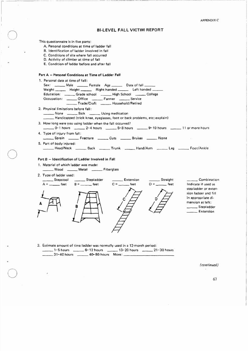
7/21/2019 Ansi a14.1 Ladders
http://slidepdf.com/reader/full/ansi-a141-ladders 72/81
APPENDIX C
81 LEVEL F LL VICTIM REPORT
This questionnaire is in five parts:
A Personal conditions at time of ladder fall
B Identification of ladder involved in fall
C. Conditions of site where fall occurred
D Activity of climber at time of fall
E Condition of ladder before and after fall
Part A - Personal Conditions at Time of Ladder Fa
1 Personal data at time of fall:
Sex: Male Female Age Date of fall
Weight Height Right handed Left handed
Education: Grade school High School College
Occupation: Office Farmer ervice
Trade/Craft Household/Retired
2 Physical limitations before fall:
None Sick Using medication
Handicapped (trick knee, eyeglasses foot or back problems etc; explain)
3. How long were you using ladder when the fall occurred?
0-1 hours 2-4 hours 5-8 hours 9-10 hours 11 or more hours
4. Type of injury from fall:
Sprain Fracture Cuts Bruises None
5. Part of body injured:
Head/Neck Back runk Hand/Arm eg FootiAnkle
Part 8 - Identification of Ladder Involved in Fa
1 Material of which ladder was made:
Wood Metal Fiberglass
2Type of
ladder used:Steps ool Stepladder Extension Straight
A:: eet B:: feet C = feet D = feet
3. Estimate amount of time ladder was normally used in a 12-month period:
1-5 hours 6-12 hours 13-20 hours 21-30 hours
31-40 hours 40-BOhours More:
Combination
Indicate it used as
stepladder or exten·
sian ladaer and fill
in appropriate di·
mension at left:
Stepladder
Extension
con tinued)
67

7/21/2019 Ansi a14.1 Ladders
http://slidepdf.com/reader/full/ansi-a141-ladders 73/81
APPENDlXC
Part C - Conditions of Site Where Fall Occurred:
1 Location of site:
nside Outside
2 Weather if applicable):
Dry Windy Rain now cover Clear
3. Ladder base support can be more than one characteristic):
oil Grass _ In shrubs Gravel
_ _ Concrete _ Blacktop ___ Tile WoodOther explain):
4. Condition of base:
Level
Uneven
Slippery
Hard
Soft
Yes o
5 Condition at top support extension ladder only ):
Gutter Tree Attic or 10ft
Wall: Wood Metal ___ Brick
Other:
Part D - Activity of Climber at Time of Fall
. What were you doing?
Painting ___ Cleaning __ _ Pruning Storing
Working on: Roof Wall GutterOther: __________________________ ___
2. Height of work area ceiling. shelf. window tree branch. etc): eet
3a. Stepladder:
68
When fall occurred I was:
Climbing down
Climbing up
tandingReaching up
Reaching to the side
Coming down to A from above
Going up from A 10 above
Location
on ladder:A
____ 8C
D
E
_ G
Stepladder closed. leaning against:
_Wall
_Tree
_Other continued)

7/21/2019 Ansi a14.1 Ladders
http://slidepdf.com/reader/full/ansi-a141-ladders 74/81
)
3b. Extension ladder:
When fall occurred I was:
Climbing down
Climbing up
tanding
Reaching up
Reaching up the side
Coming off roof
Going on roof
Location
on ladder:A
C
0
EF
G
Extension ladder used as straight ladder:
Taken apart
Fully closed
4 What appeared to happen at the time?f the fall?
Lost balance Step or rung broke
Missed a step or rung Ladder collapsed
Ladder tipped Electric shock
Ladder slipped at top Extension lock failed
Ladder slipped at bottom Wind blown
: Personal assessment of the fall:
Was using the right ladder for the job
Placed the ladder correctly
Read labels and other literature
Personal condition was a factor
Yes No
APPENDIX C
WALL
FT
vWALL
GROUND
continued)
69
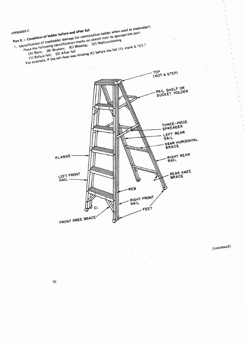
7/21/2019 Ansi a14.1 Ladders
http://slidepdf.com/reader/full/ansi-a141-ladders 75/81
Part E _ condition 01 ladder ,,10, .nd fall\. lO.n,\I\<ot\on 0' ,,,olad
Oo' d. ,... Ie< _bi •tiOn
ladOo' h'· d , t < o l ~ d d ) 'PI.' tM 'olloW
i09
'd.ntme.tiC . . ,,,,., o . <t,,h • • to , ,o,oP ' 0IA) s.nt; IS) S,o,.n; Ie) i . ' : 0) , , ~ u n c t i o n n1\\ S. 'o II: (2) Aft fall .for . ,, '°
1
• ,-., tn. , , ' t ,oot ,. ,,,,,,. Ie) ,10 thO .11 1\\· ,a e '
PAIL S H E U ~ R
BUCKEl HOLDER
I ~ ~ ~ ~ ~ n.\REE-P\ECESPRE ADER
LE fi REAR
Rto \L\ \ t t : : : : : : ; : ~ ~ ~ - - - REAR HOR\ZONiALBRACE
10

7/21/2019 Ansi a14.1 Ladders
http://slidepdf.com/reader/full/ansi-a141-ladders 76/81
2. 'd,ntifl ,;on 0 ten,;on 0 , , ; ,h ' dd d,, ' ' ' (0' ,o ,b;n,,;on ,,,,de' wh'n d ,,,,n,;on ',dd,<I'
p,,,, ,h ' onow;n, ;dentl ,ion ,,'k' on ,k ,h nex' 0 ,pp,oP,i' oa<
(Al Bent; (B) Broken; tC) Missing; to) Malfunctioning
(1) Before fall; 2) After fallFo, , 'P' il th ,i t oot w ' in, (C\ b,'o the II (11. ,,,k i, ..c1.
END CAP~6 in OR 12 in ENo SPACINGt ~
FLY ORSECTIO
TOPN
FLANGE
ROPE
KS
PLASTIC RAILCLOSURES
~IOOT
ASSEMBLY ' CI
~
n ......~
.....
-r=
-
If I
....
~
...-
-SIDE RAIL
WEB
BASESECTION
CENTER SWIVEL
PULLEY
L.UNGS
FLAT OR ROUND)
6 in OR I2 in ENe.
r , SPACING
tiI
71

7/21/2019 Ansi a14.1 Ladders
http://slidepdf.com/reader/full/ansi-a141-ladders 77/81

7/21/2019 Ansi a14.1 Ladders
http://slidepdf.com/reader/full/ansi-a141-ladders 78/81

7/21/2019 Ansi a14.1 Ladders
http://slidepdf.com/reader/full/ansi-a141-ladders 79/81

7/21/2019 Ansi a14.1 Ladders
http://slidepdf.com/reader/full/ansi-a141-ladders 80/81
7/21/2019 Ansi a14.1 Ladders
http://slidepdf.com/reader/full/ansi-a141-ladders 81/81
merican ational Standards
The standard in this booklet is one of more than 10,000 standards approved
to date by the American National Standards Institute.
The Standards Institute provides the machinery for creating voluntary stan
dards. t serves to eliminate duplication of standards activities and to weld
conflicting standards into single, nationally accepted standards under the
designation American National Standards.
Each standard represents general agreement among maker, seller, and user
groups as to the best current practice with regard to some specific problem.
Thus the completed standards cut across the whole fabric of production,
distribution, and consumption of goods and services. American NationalStandards, by reason of Institute procedures, reflect a national consensus
of manufacturers, consumers, and s c i e n t i f i c ~ technical, and professional orga
nizations, and governmental agencies. The completed standards are used
widely by industry and commerce and often by municipal, state, and federal
governments.
The Standards I n s ~ i t u t e under. whose auspices this work is being done, is the
United States clearinghouse and coordinating body for voluntary standards
activity on the national level. It is a federation of trade associations, techni
cal societies, professional groups, and consumer organizations. Some 1000
companies are affiliatecs with the Institute as company members.
The American National Standards Institute is the United States member ofthe International Organization for Standardization ISO) and the Interna
tional Electrotechnical Commission (IEC). Through these channels U.S. stan-
dards interests make their positions felt on the international level. American
National Standards are on file in the libraries of the national standards bodies
of more than 60 countries.
American National Standards Institute, Inc