Annual Certification of Maintenance Procedures Sample − 6 ... · PDF fileMNT-FIXED-017...
32
Your Company Here MNT-INDEX Rev. 0 Anytown, USA Maintenance Procedure Printed:3/7/2017 CONTROL COPY Page 1 of 4 Mechanical Integrity Maintenance Procedure Index Annual Certification of Maintenance Procedures I hereby certify these active maintenance procedures were developed utilizing input and review of the employees and are current and accurate as of their individual effective date. Name: ______________________________ Title: ______________________________ Signature: ______________________________ Date: ______________________________ Administration Procedure No. Description Directory Date Issued Rev # MNT-ADM-001 Development of Maintenance Procedures Administration 4/18/2013 0 MNT-ADM-002 QA/QC Plan Administration 4/18/2013 0 Electrical Equipment Procedure No. Description Directory Date Issued Rev # MNT-ELCT-001 Service/Maintenance for 600V Electrical Cable Electrical 4/18/2013 0 MNT-ELCT-002 Field Testing/Troubleshooting of an Electric Motor Electrical 4/18/2013 0 MNT-ELCT-003 Replacing Explosion Proof Receptacle Electrical 4/18/2013 0 MNT-ELCT-004 Electrical Substation Periodic Inspection Electrical 4/18/2013 0 MNT-ELCT-005 Cutler Hammer 600V Motor Starters Electrical 4/18/2013 0 MNT-ELCT-006 Procedure for Substation Service Transformers Electrical 4/18/2013 0 MNT-ELCT-007 Maintenance Procedure for Equipment Grounding Electrical 4/18/2013 0 MNT-ELCT-008 Troubleshoot/Removal of a 480V Motor Starter Electrical 4/18/2013 0 MNT-ELCT-009 Procedure for Replacing Lamps Electrical 4/18/2013 0 MNT-ELCT-010 Megger Test for Insulation Breakdown Electrical 4/18/2013 0 MNT-ELCT-011 UPS / Uniterruptable Power System Checkout Electrical 4/18/2013 0 Fixed Equipment Procedure No. Description Directory Date Issued Rev # MNT-FIXED-001 Remove, Clean and Re-Install Bundle from an Exchanger Fixed Equip 4/18/2013 0 MNT-FIXED-002 Test and Repair of an Exchanger (in place) Fixed Equip 4/18/2013 0 MNT-FIXED-003 Clean, Inspect and Repair of a Heater Fixed Equip 4/18/2013 0 MNT-FIXED-004 Clean, Inspect and Repair of a Tower Fixed Equip 4/18/2013 0 MNT-FIXED-005 Clean, Inspect and Repair of a Drum Fixed Equip 4/18/2013 0 MNT-FIXED-006 Clean, Inspect and Repair of a Vessel Fixed Equip 4/18/2013 0 MNT-FIXED-007 Clean, Inspect and Repair of a Tank Fixed Equip 4/18/2013 0 MNT-FIXED-008 Installing Isolation Blind and/or Blind Flange to Processing Piping or Equipment Fixed Equip 4/18/2013 0 MNT-FIXED-009 Installation/Removal of Screwed Piping Sections Fixed Equip 4/18/2013 0 MNT-FIXED-010 Replacement of Flanged Piping Sections Fixed Equip 4/18/2013 0 Sample 6 of 97 www.industrydocs.website
Transcript of Annual Certification of Maintenance Procedures Sample − 6 ... · PDF fileMNT-FIXED-017...

Your Company Here MNT-INDEX Rev. 0 Anytown, USA Maintenance Procedure
Printed:3/7/2017 CONTROL COPY Page 1 of 4
Mechanical Integrity Maintenance Procedure Index
Annual Certification of Maintenance Procedures I hereby certify these active maintenance procedures were developed utilizing input and review of the employees and are current and accurate as of their individual effective date. Name: ______________________________ Title: ______________________________
Signature:
______________________________
Date:
______________________________
Administration
Procedure No. Description Directory Date Issued
Rev #
MNT-ADM-001 Development of Maintenance Procedures Administration 4/18/2013 0
MNT-ADM-002 QA/QC Plan Administration 4/18/2013 0
Electrical Equipment
Procedure No. Description Directory Date Issued
Rev #
MNT-ELCT-001 Service/Maintenance for 600V Electrical Cable Electrical 4/18/2013 0
MNT-ELCT-002 Field Testing/Troubleshooting of an Electric Motor Electrical 4/18/2013 0
MNT-ELCT-003 Replacing Explosion Proof Receptacle Electrical 4/18/2013 0
MNT-ELCT-004 Electrical Substation Periodic Inspection Electrical 4/18/2013 0
MNT-ELCT-005 Cutler Hammer 600V Motor Starters Electrical 4/18/2013 0
MNT-ELCT-006 Procedure for Substation Service Transformers Electrical 4/18/2013 0
MNT-ELCT-007 Maintenance Procedure for Equipment Grounding Electrical 4/18/2013 0
MNT-ELCT-008 Troubleshoot/Removal of a 480V Motor Starter Electrical 4/18/2013 0
MNT-ELCT-009 Procedure for Replacing Lamps Electrical 4/18/2013 0
MNT-ELCT-010 Megger Test for Insulation Breakdown Electrical 4/18/2013 0
MNT-ELCT-011 UPS / Uniterruptable Power System Checkout Electrical 4/18/2013 0
Fixed Equipment
Procedure No. Description Directory Date Issued
Rev #
MNT-FIXED-001 Remove, Clean and Re-Install Bundle from an Exchanger
Fixed Equip 4/18/2013 0
MNT-FIXED-002 Test and Repair of an Exchanger (in place) Fixed Equip 4/18/2013 0
MNT-FIXED-003 Clean, Inspect and Repair of a Heater Fixed Equip 4/18/2013 0
MNT-FIXED-004 Clean, Inspect and Repair of a Tower Fixed Equip 4/18/2013 0
MNT-FIXED-005 Clean, Inspect and Repair of a Drum Fixed Equip 4/18/2013 0
MNT-FIXED-006 Clean, Inspect and Repair of a Vessel Fixed Equip 4/18/2013 0
MNT-FIXED-007 Clean, Inspect and Repair of a Tank Fixed Equip 4/18/2013 0
MNT-FIXED-008 Installing Isolation Blind and/or Blind Flange to Processing Piping or Equipment
Fixed Equip 4/18/2013 0
MNT-FIXED-009 Installation/Removal of Screwed Piping Sections Fixed Equip 4/18/2013 0
MNT-FIXED-010 Replacement of Flanged Piping Sections Fixed Equip 4/18/2013 0
Sam
ple
− 6
of 9
7 −
ww
w.in
dust
rydocs.
websi
te
Your Company Here MNT-INDEX Rev. 0 Anytown, USA Maintenance Procedure
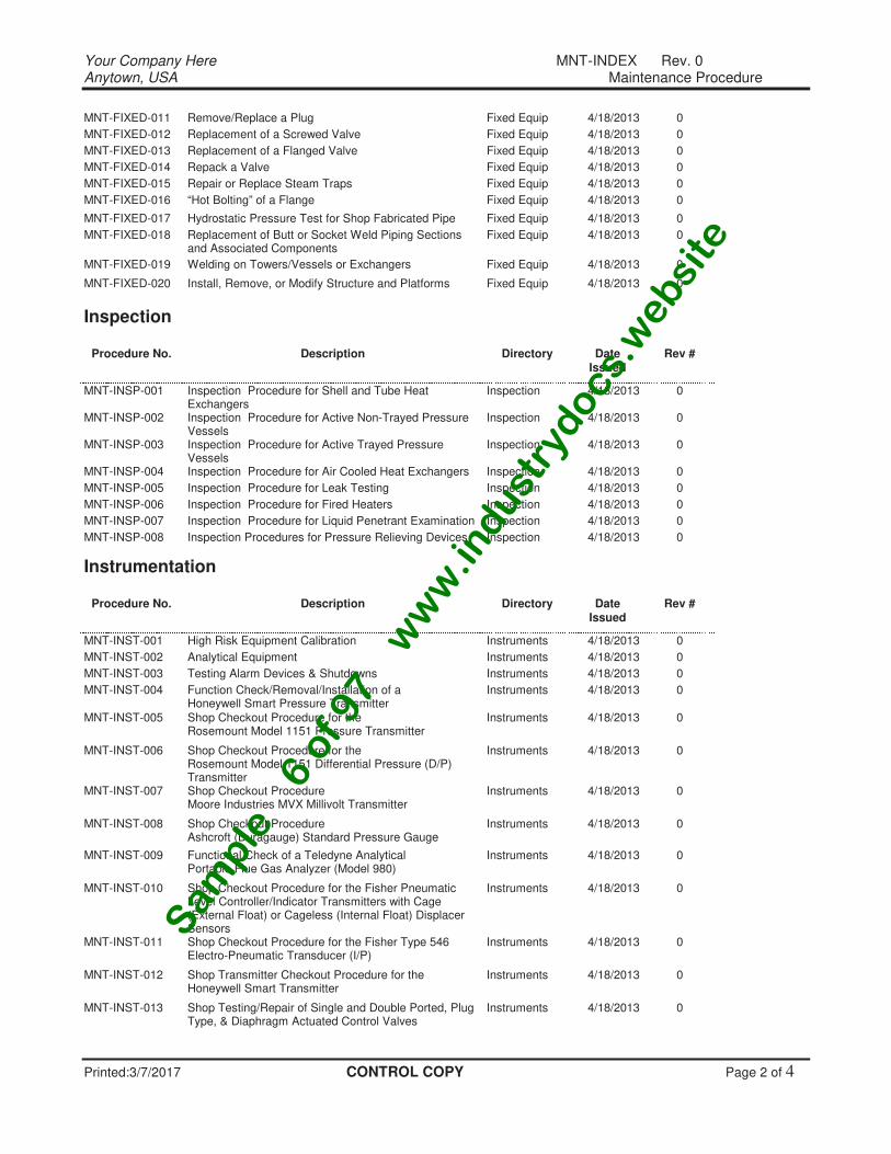
Printed:3/7/2017 CONTROL COPY Page 2 of 4
MNT-FIXED-011 Remove/Replace a Plug Fixed Equip 4/18/2013 0
MNT-FIXED-012 Replacement of a Screwed Valve Fixed Equip 4/18/2013 0
MNT-FIXED-013 Replacement of a Flanged Valve Fixed Equip 4/18/2013 0
MNT-FIXED-014 Repack a Valve Fixed Equip 4/18/2013 0
MNT-FIXED-015 Repair or Replace Steam Traps Fixed Equip 4/18/2013 0
MNT-FIXED-016 “Hot Bolting” of a Flange Fixed Equip 4/18/2013 0
MNT-FIXED-017 Hydrostatic Pressure Test for Shop Fabricated Pipe Fixed Equip 4/18/2013 0
MNT-FIXED-018 Replacement of Butt or Socket Weld Piping Sections and Associated Components
Fixed Equip 4/18/2013 0
MNT-FIXED-019 Welding on Towers/Vessels or Exchangers Fixed Equip 4/18/2013 0
MNT-FIXED-020 Install, Remove, or Modify Structure and Platforms Fixed Equip 4/18/2013 0
Inspection
Procedure No. Description Directory Date Issued
Rev #
MNT-INSP-001 Inspection Procedure for Shell and Tube Heat Exchangers
Inspection 4/18/2013 0
MNT-INSP-002 Inspection Procedure for Active Non-Trayed Pressure Vessels
Inspection 4/18/2013 0
MNT-INSP-003 Inspection Procedure for Active Trayed Pressure Vessels
Inspection 4/18/2013 0
MNT-INSP-004 Inspection Procedure for Air Cooled Heat Exchangers Inspection 4/18/2013 0
MNT-INSP-005 Inspection Procedure for Leak Testing Inspection 4/18/2013 0
MNT-INSP-006 Inspection Procedure for Fired Heaters Inspection 4/18/2013 0
MNT-INSP-007 Inspection Procedure for Liquid Penetrant Examination Inspection 4/18/2013 0
MNT-INSP-008 Inspection Procedures for Pressure Relieving Devices Inspection 4/18/2013 0
Instrumentation
Procedure No. Description Directory Date Issued
Rev #
MNT-INST-001 High Risk Equipment Calibration Instruments 4/18/2013 0
MNT-INST-002 Analytical Equipment Instruments 4/18/2013 0
MNT-INST-003 Testing Alarm Devices & Shutdowns Instruments 4/18/2013 0
MNT-INST-004 Function Check/Removal/Installation of a Honeywell Smart Pressure Transmitter
Instruments 4/18/2013 0
MNT-INST-005 Shop Checkout Procedure for the Rosemount Model 1151 Pressure Transmitter
Instruments 4/18/2013 0
MNT-INST-006 Shop Checkout Procedure for the Rosemount Model 1151 Differential Pressure (D/P) Transmitter
Instruments 4/18/2013 0
MNT-INST-007 Shop Checkout Procedure Moore Industries MVX Millivolt Transmitter
Instruments 4/18/2013 0
MNT-INST-008 Shop Checkout Procedure Ashcroft (Duragauge) Standard Pressure Gauge
Instruments 4/18/2013 0
MNT-INST-009 Functional Check of a Teledyne Analytical Portable Flue Gas Analyzer (Model 980)
Instruments 4/18/2013 0
MNT-INST-010 Shop Checkout Procedure for the Fisher Pneumatic Level Controller/Indicator Transmitters with Cage (External Float) or Cageless (Internal Float) Displacer Sensors
Instruments 4/18/2013 0
MNT-INST-011 Shop Checkout Procedure for the Fisher Type 546 Electro-Pneumatic Transducer (I/P)
Instruments 4/18/2013 0
MNT-INST-012 Shop Transmitter Checkout Procedure for the Honeywell Smart Transmitter
Instruments 4/18/2013 0
MNT-INST-013 Shop Testing/Repair of Single and Double Ported, Plug Type, & Diaphragm Actuated Control Valves
Instruments 4/18/2013 0
Sam
ple
− 6
of 9
7 −
ww
w.in
dust
rydocs.
websi
te
Your Company Here MNT-INDEX Rev. 0 Anytown, USA Maintenance Procedure
Printed:3/7/2017 CONTROL COPY Page 3 of 4
MNT-INST-014 Function Check/Removal/Installation of a Flow Transmitter (Honeywell Smart)
Instruments 4/18/2013 0
MNT-INST-015 Function Check/Removal/Installation of a Pressure Transmitter (Honeywell Smart)
Instruments 4/18/2013 0
MNT-INST-016 Function Check/Removal of a Cage Type Displacer Level Transmitter
Instruments 4/18/2013 0
MNT-INST-017 Function Check/Removal of a Control Valve Instruments 4/18/2013 0
MNT-INST-018 Function Check of a Precision Continuous Viscometer Instruments 4/18/2013 0
MNT-INST-019 Replacement of a Butterfly Valve Instruments 4/18/2013 0
MNT-INST-020 Installation/Removal/Function Check of a Pressure Switch
Instruments 4/18/2013 0
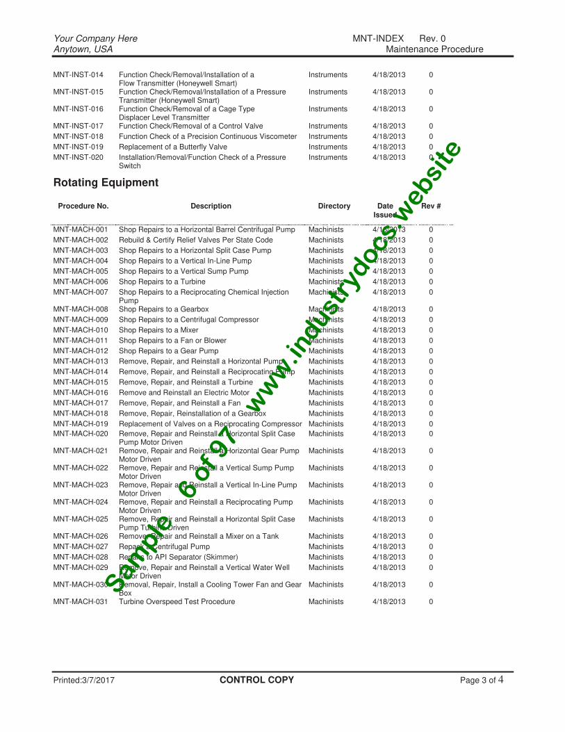
Rotating Equipment
Procedure No. Description Directory Date Issued
Rev #
MNT-MACH-001 Shop Repairs to a Horizontal Barrel Centrifugal Pump Machinists 4/18/2013 0
MNT-MACH-002 Rebuild & Certify Relief Valves Per State Code Machinists 4/18/2013 0
MNT-MACH-003 Shop Repairs to a Horizontal Split Case Pump Machinists 4/18/2013 0
MNT-MACH-004 Shop Repairs to a Vertical In-Line Pump Machinists 4/18/2013 0
MNT-MACH-005 Shop Repairs to a Vertical Sump Pump Machinists 4/18/2013 0
MNT-MACH-006 Shop Repairs to a Turbine Machinists 4/18/2013 0
MNT-MACH-007 Shop Repairs to a Reciprocating Chemical Injection Pump
Machinists 4/18/2013 0
MNT-MACH-008 Shop Repairs to a Gearbox Machinists 4/18/2013 0
MNT-MACH-009 Shop Repairs to a Centrifugal Compressor Machinists 4/18/2013 0
MNT-MACH-010 Shop Repairs to a Mixer Machinists 4/18/2013 0
MNT-MACH-011 Shop Repairs to a Fan or Blower Machinists 4/18/2013 0
MNT-MACH-012 Shop Repairs to a Gear Pump Machinists 4/18/2013 0
MNT-MACH-013 Remove, Repair, and Reinstall a Horizontal Pump Machinists 4/18/2013 0
MNT-MACH-014 Remove, Repair, and Reinstall a Reciprocating Pump Machinists 4/18/2013 0
MNT-MACH-015 Remove, Repair, and Reinstall a Turbine Machinists 4/18/2013 0
MNT-MACH-016 Remove and Reinstall an Electric Motor Machinists 4/18/2013 0
MNT-MACH-017 Remove, Repair, and Reinstall a Fan Machinists 4/18/2013 0
MNT-MACH-018 Remove, Repair, Reinstallation of a Gearbox Machinists 4/18/2013 0
MNT-MACH-019 Replacement of Valves on a Reciprocating Compressor Machinists 4/18/2013 0
MNT-MACH-020 Remove, Repair and Reinstall a Horizontal Split Case Pump Motor Driven
Machinists 4/18/2013 0
MNT-MACH-021 Remove, Repair and Reinstall a Horizontal Gear Pump Motor Driven
Machinists 4/18/2013 0
MNT-MACH-022 Remove, Repair and Reinstall a Vertical Sump Pump Motor Driven
Machinists 4/18/2013 0
MNT-MACH-023 Remove, Repair and Reinstall a Vertical In-Line Pump Motor Driven
Machinists 4/18/2013 0
MNT-MACH-024 Remove, Repair and Reinstall a Reciprocating Pump Motor Driven
Machinists 4/18/2013 0
MNT-MACH-025 Remove, Repair and Reinstall a Horizontal Split Case Pump Turbine Driven
Machinists 4/18/2013 0
MNT-MACH-026 Remove, Repair and Reinstall a Mixer on a Tank Machinists 4/18/2013 0
MNT-MACH-027 Repack a Centrifugal Pump Machinists 4/18/2013 0
MNT-MACH-028 Repairs to API Separator (Skimmer) Machinists 4/18/2013 0
MNT-MACH-029 Remove, Repair and Reinstall a Vertical Water Well Motor Driven
Machinists 4/18/2013 0
MNT-MACH-030 Removal, Repair, Install a Cooling Tower Fan and Gear Box
Machinists 4/18/2013 0
MNT-MACH-031 Turbine Overspeed Test Procedure Machinists 4/18/2013 0
Sam
ple
− 6
of 9
7 −
ww
w.in
dust
rydocs.
websi
te
Your Company Here MNT-INDEX Rev. 0 Anytown, USA Maintenance Procedure
Printed:3/7/2017 CONTROL COPY Page 4 of 4
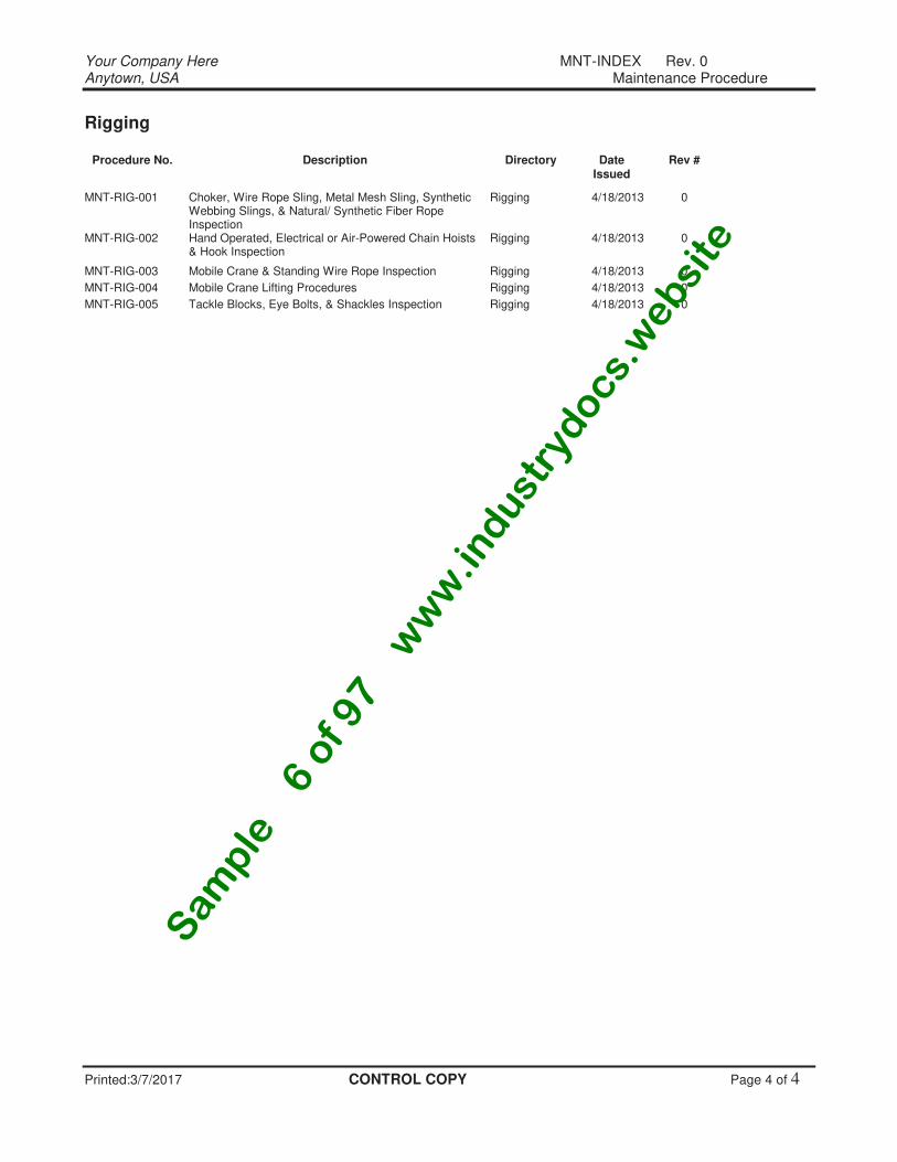
Rigging
Procedure No. Description Directory Date Issued
Rev #
MNT-RIG-001 Choker, Wire Rope Sling, Metal Mesh Sling, Synthetic Webbing Slings, & Natural/ Synthetic Fiber Rope Inspection
Rigging 4/18/2013 0
MNT-RIG-002 Hand Operated, Electrical or Air-Powered Chain Hoists & Hook Inspection
Rigging 4/18/2013 0
MNT-RIG-003 Mobile Crane & Standing Wire Rope Inspection Rigging 4/18/2013 0
MNT-RIG-004 Mobile Crane Lifting Procedures Rigging 4/18/2013 0
MNT-RIG-005 Tackle Blocks, Eye Bolts, & Shackles Inspection Rigging 4/18/2013 0
Sam
ple
− 6
of 9
7 −
ww
w.in
dust
rydocs.
websi
te
MNT-ADM-001 Rev. 0 Administrative Procedure
Printed:3/7/2017 CONTROL COPY Page 1 of 5
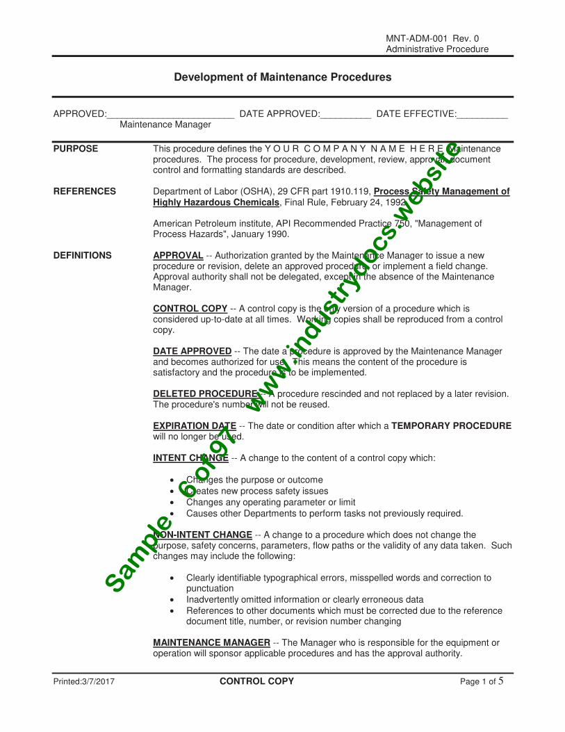
Development of Maintenance Procedures
APPROVED:_________________________ DATE APPROVED:__________ DATE EFFECTIVE:__________ Maintenance Manager
PURPOSE This procedure defines the Y O U R C O M P A N Y N A M E H E R E Maintenance procedures. The process for procedure, development, review, approval, document control and formatting standards are described.
REFERENCES Department of Labor (OSHA), 29 CFR part 1910.119, Process Safety Management of
Highly Hazardous Chemicals, Final Rule, February 24, 1992. American Petroleum institute, API Recommended Practice 750, "Management of
Process Hazards", January 1990. DEFINITIONS APPROVAL -- Authorization granted by the Maintenance Manager to issue a new
procedure or revision, delete an approved procedure, or implement a field change. Approval authority shall not be delegated, except in the absence of the Maintenance Manager.
CONTROL COPY -- A control copy is the only version of a procedure which is
considered up-to-date at all times. Working copies shall be reproduced from a control copy.
DATE APPROVED -- The date a procedure is approved by the Maintenance Manager
and becomes authorized for use. This means the content of the procedure is satisfactory and the procedure is to be implemented.
DELETED PROCEDURE -- A procedure rescinded and not replaced by a later revision.
The procedure's number will not be reused. EXPIRATION DATE -- The date or condition after which a TEMPORARY PROCEDURE
will no longer be used. INTENT CHANGE -- A change to the content of a control copy which:
• Changes the purpose or outcome
• Creates new process safety issues
• Changes any operating parameter or limit
• Causes other Departments to perform tasks not previously required. NON-INTENT CHANGE -- A change to a procedure which does not change the
purpose, safety concerns, parameters, flow paths or the validity of any data taken. Such changes may include the following:
• Clearly identifiable typographical errors, misspelled words and correction to punctuation
• Inadvertently omitted information or clearly erroneous data
• References to other documents which must be corrected due to the reference document title, number, or revision number changing
MAINTENANCE MANAGER -- The Manager who is responsible for the equipment or
operation will sponsor applicable procedures and has the approval authority.
Sam
ple
− 6
of 9
7 −
ww
w.in
dust
rydocs.
websi
te
MNT-ADM-001 Rev. 0 Administrative Procedure
Printed:3/7/2017 CONTROL COPY Page 2 of 5
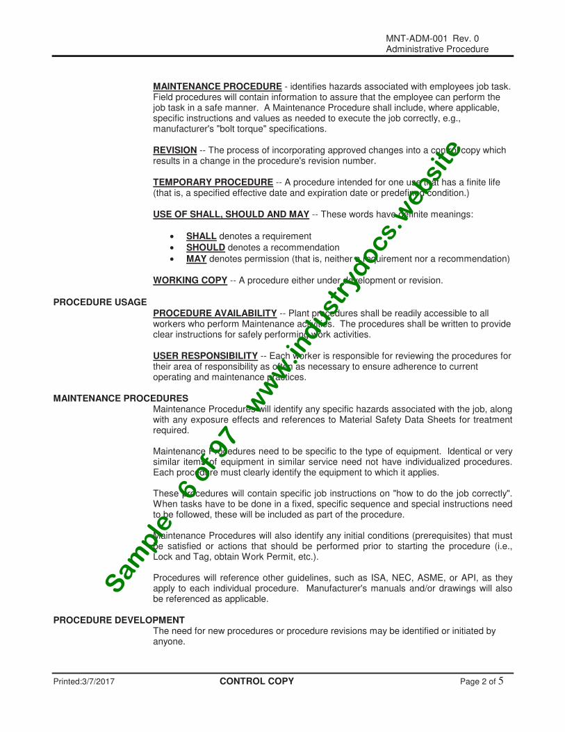
MAINTENANCE PROCEDURE - identifies hazards associated with employees job task.
Field procedures will contain information to assure that the employee can perform the job task in a safe manner. A Maintenance Procedure shall include, where applicable, specific instructions and values as needed to execute the job correctly, e.g., manufacturer's "bolt torque" specifications.
REVISION -- The process of incorporating approved changes into a control copy which
results in a change in the procedure's revision number. TEMPORARY PROCEDURE -- A procedure intended for one use that has a finite life
(that is, a specified effective date and expiration date or predefined condition.) USE OF SHALL, SHOULD AND MAY -- These words have definite meanings:
• SHALL denotes a requirement
• SHOULD denotes a recommendation
• MAY denotes permission (that is, neither a requirement nor a recommendation) WORKING COPY -- A procedure either under development or revision. PROCEDURE USAGE PROCEDURE AVAILABILITY -- Plant procedures shall be readily accessible to all
workers who perform Maintenance activities. The procedures shall be written to provide clear instructions for safely performing work activities.
USER RESPONSIBILITY -- Each worker is responsible for reviewing the procedures for
their area of responsibility as often as necessary to ensure adherence to current operating and maintenance practices.
MAINTENANCE PROCEDURES Maintenance Procedures will identify any specific hazards associated with the job, along
with any exposure effects and references to Material Safety Data Sheets for treatment required.
Maintenance Procedures need to be specific to the type of equipment. Identical or very
similar items of equipment in similar service need not have individualized procedures. Each procedure must clearly identify the equipment to which it applies.
These procedures will contain specific job instructions on "how to do the job correctly".
When tasks have to be done in a fixed, specific sequence and special instructions need to be followed, these will be included as part of the procedure.
Maintenance Procedures will also identify any initial conditions (prerequisites) that must
be satisfied or actions that should be performed prior to starting the procedure (i.e., Lock and Tag, obtain Work Permit, etc.).
Procedures will reference other guidelines, such as ISA, NEC, ASME, or API, as they
apply to each individual procedure. Manufacturer's manuals and/or drawings will also be referenced as applicable.
PROCEDURE DEVELOPMENT The need for new procedures or procedure revisions may be identified or initiated by
anyone.
Sam
ple
− 6
of 9
7 −
ww
w.in
dust
rydocs.
websi
te
MNT-ADM-001 Rev. 0 Administrative Procedure
Printed:3/7/2017 CONTROL COPY Page 3 of 5
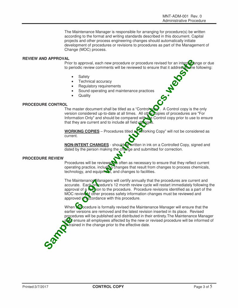
The Maintenance Manager is responsible for arranging for procedure(s) be written according to the format and writing standards described in this document. Capital projects and other process engineering changes should automatically initiate development of procedures or revisions to procedures as part of the Management of Change (MOC) process.
REVIEW AND APPROVAL Prior to approval, each new procedure or procedure revised for an intent change or due
to periodic review comments will be reviewed to ensure that it addresses the following:
• Safety
• Technical accuracy
• Regulatory requirements
• Sound operating and maintenance practices
• Quality PROCEDURE CONTROL The master document shall be titled as a “Control copy”. A Control copy is the only
version considered up-to-date at all times. All other copies of procedures are "For Information Only" and should be compared with the Control copy prior to use to ensure that they are current and to include all field changes.
WORKING COPIES – Procedures titled as “Working Copy” will not be considered as
current. NON-INTENT CHANGES - should be written in ink on a Controlled Copy, signed and
dated by the person making the change and submitted for correction. PROCEDURE REVIEW Procedures will be reviewed as often as necessary to ensure that they reflect current
operating practice, including changes that result from changes to process chemicals, technology, and equipment, and changes to facilities.
The Maintenance Managers will certify annually that the procedures are current and
accurate. Each procedure's 12 month review cycle will restart immediately following the approval of a revision to the procedure. Procedure revisions identified as a part of the MOC review of other process safety information changes must be reviewed and approved in accordance with this procedure.
When a procedure is formally revised the Maintenance Manager will ensure that the
earlier versions are removed and the latest revision inserted in its place. Revised procedures will be published and distributed in their entirety.The Maintenance Manager shall ensure all employees affected by the new or revised procedure will be informed of or trained in the change prior to the effective date.
Sam
ple
− 6
of 9
7 −
ww
w.in
dust
rydocs.
websi
te
MNT-ADM-001 Rev. 0 Administrative Procedure
Printed:3/7/2017 CONTROL COPY Page 4 of 5
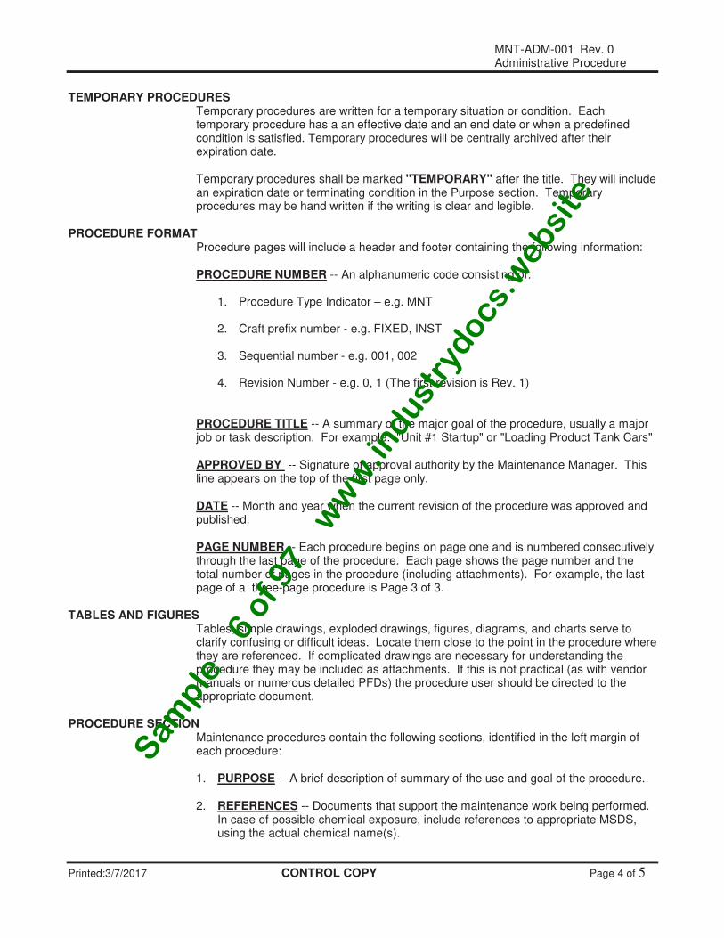
TEMPORARY PROCEDURES Temporary procedures are written for a temporary situation or condition. Each
temporary procedure has a an effective date and an end date or when a predefined condition is satisfied. Temporary procedures will be centrally archived after their expiration date.
Temporary procedures shall be marked "TEMPORARY" after the title. They will include
an expiration date or terminating condition in the Purpose section. Temporary procedures may be hand written if the writing is clear and legible.
PROCEDURE FORMAT Procedure pages will include a header and footer containing the following information: PROCEDURE NUMBER -- An alphanumeric code consisting of:
1. Procedure Type Indicator – e.g. MNT 2. Craft prefix number - e.g. FIXED, INST 3. Sequential number - e.g. 001, 002 4. Revision Number - e.g. 0, 1 (The first revision is Rev. 1)
PROCEDURE TITLE -- A summary of the major goal of the procedure, usually a major
job or task description. For example: "Unit #1 Startup" or "Loading Product Tank Cars" APPROVED BY -- Signature of approval authority by the Maintenance Manager. This
line appears on the top of the first page only. DATE -- Month and year when the current revision of the procedure was approved and
published. PAGE NUMBER -- Each procedure begins on page one and is numbered consecutively
through the last page of the procedure. Each page shows the page number and the total number of pages in the procedure (including attachments). For example, the last page of a three-page procedure is Page 3 of 3.
TABLES AND FIGURES Tables, simple drawings, exploded drawings, figures, diagrams, and charts serve to
clarify confusing or difficult ideas. Locate them close to the point in the procedure where they are referenced. If complicated drawings are necessary for understanding the procedure they may be included as attachments. If this is not practical (as with vendor manuals or numerous detailed PFDs) the procedure user should be directed to the appropriate document.
PROCEDURE SECTION Maintenance procedures contain the following sections, identified in the left margin of
each procedure: 1. PURPOSE -- A brief description of summary of the use and goal of the procedure. 2. REFERENCES -- Documents that support the maintenance work being performed.
In case of possible chemical exposure, include references to appropriate MSDS, using the actual chemical name(s).
Sam
ple
− 6
of 9
7 −
ww
w.in
dust
rydocs.
websi
te

MNT-ADM-001 Rev. 0 Administrative Procedure
Printed:3/7/2017 CONTROL COPY Page 5 of 5
3. PRECAUTIONS -- A brief description of any dangerous conditions that exist or
could be encountered while performing the procedure as identified by a Job Hazard Analysis.
4. SPECIAL TOOLS AND EQUIPMENT -- A list of equipment or materials unique to
the procedure or which should be in place before beginning the procedure. This section would not include normal Personal Protection Equipment (PPE) worn to meet general plant safety requirements.
5. PREREQUISITES -- Actions or conditions which shall be performed or verified
before starting the procedure. The technician skill level that the work requires will be stated here. Other job planning information is identified here as well as special training and regulatory requirements.
6. PROCEDURE -- The step-by-step instructions for achieving the purpose of the
procedure. Procedural steps will consist of an action and the object of the action. For example: Mechanic 1. VISUALLY INSPECT gasket seat for signs of rusting or pitting. 2. WIPE the gasket seat area with a cloth soaked in machine oil.
NOTES contain information that will help in the performance or understanding of a procedural step. Notes will precede the procedural step to which they refer. It is advisable to limit the use of "nice to know information" in notes as well as in procedural steps. Notes do not normally contain actions. Notes will be designated as shown below:
CAUTIONS are placed before a step to identify potential or actual hazards that could injure personnel, damage equipment or reduce a component's mechanical integrity.
END OF PROCEDURE The centered word { END }, in bold type, shall appear after the last step or paragraph of
a procedure.
END
Sam
ple
− 6
of 9
7 −
ww
w.in
dust
rydocs.
websi
te

MNT-ELCT-001 Rev.0 Maintenance Procedure
Printed: 3/7/2017 WORKING COPY Page 1 of 3
Service/Maintenance Procedure for 600V Electrical Cable
APPROVED:_________________________ DATE APPROVED:__________ DATE EFFECTIVE:__________ Maintenance Manager
PURPOSE This procedure describes the service and maintenance of 600V electrical cable This procedure applies to all electrical personnel that perform or assist in this work. All Maintenance Electrical Personnel that perform or assist in accomplishing this work will follow all procedures.
.
REFERENCES • MATERIAL SAFETY DATA SHEETS
• Safe Work Permit Procedure
• Lock Out/ Tag Out Procedure
• Safety Manual SPECIAL Minimum 5KV Megger with 20,000 Mohm scale. EQUIPMENT PREREQUISITE This procedure requires qualified craftsmen. 1. REVIEW this procedure with the electrical personnel to ENSURE all steps
and cautions are CLEAR and all hazards have been DEFINED. 2. Electrical personnel shall VERIFY that all safety equipment in the sub
station is in good working order. 3. If electrical lockout is required, REFER to Lock Out/ Tag Out Procedure. 4. When involving electrical distribution, NOTIFY central control operators that a power distribution system will be out of service, and what will be
affected. 5. Refer to Electrical Switching Orders Procedure. PRECAUTION Personnel will be exposed to low or high voltages. The following hazards are
associated with electrical energy and safety precautions must be exercised: 1. Shock 2. Arc (Flash) 3. Blast
Exposure or contact with any of these hazards will result in burns, severe and/or possibly fatal injuries. Wear proper protective gear, barricade area to be tested.
Sam
ple
− 6
of 9
7 −
ww
w.in
dust
rydocs.
websi
te
MNT-ELCT-001 Rev.0 Maintenance Procedure
Printed: 3/7/2017 WORKING COPY Page 2 of 3
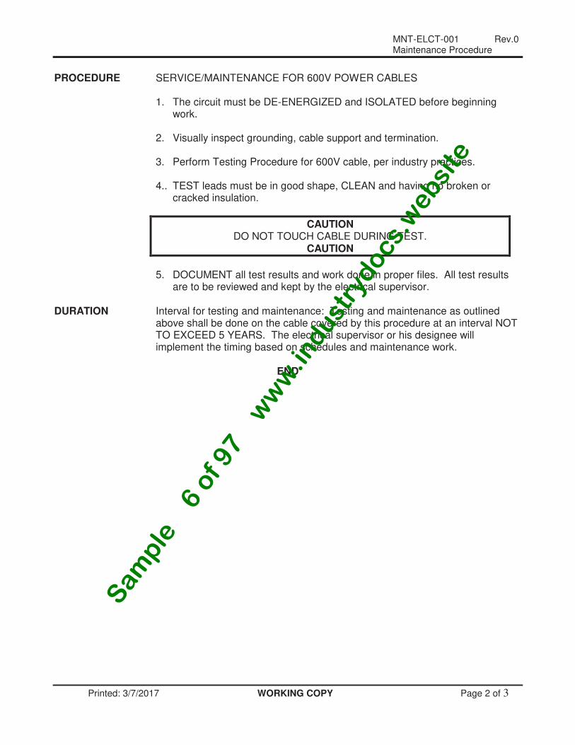
PROCEDURE SERVICE/MAINTENANCE FOR 600V POWER CABLES 1. The circuit must be DE-ENERGIZED and ISOLATED before beginning
work. 2. Visually inspect grounding, cable support and termination. 3. Perform Testing Procedure for 600V cable, per industry practices. 4.. TEST leads must be in good shape, CLEAN and having no broken or
cracked insulation.
CAUTION DO NOT TOUCH CABLE DURING TEST.
CAUTION
5. DOCUMENT all test results and work done in proper files. All test results
are to be reviewed and kept by the electrical supervisor. DURATION Interval for testing and maintenance: Testing and maintenance as outlined
above shall be done on the cable covered by this procedure at an interval NOT TO EXCEED 5 YEARS. The electrical supervisor or his designee will implement the timing based on schedules and maintenance work.
END
Sam
ple
− 6
of 9
7 −
ww
w.in
dust
rydocs.
websi
te
MNT-ELCT-001 Rev. 0 Maintenance Procedure
Printed: 3/7/2017 WORKING COPY Page 3 of 3
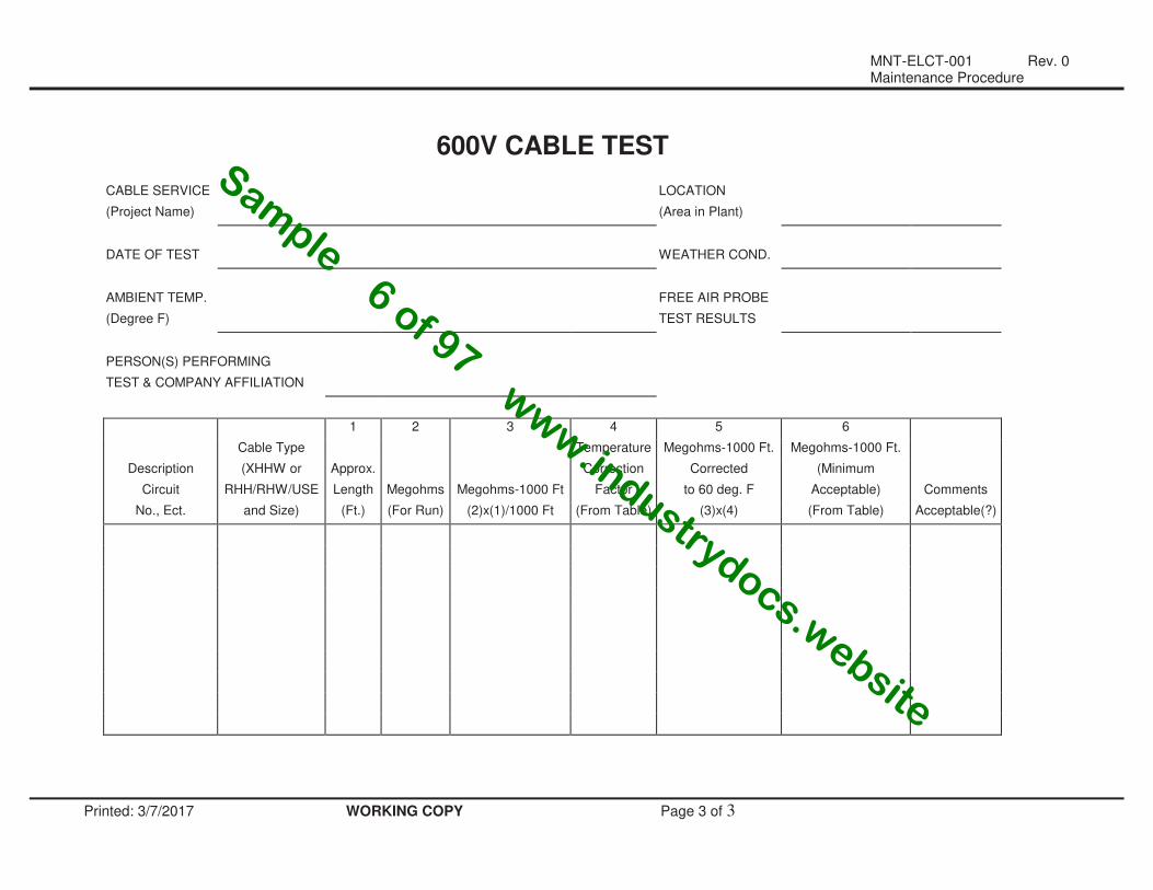
600V CABLE TEST
CABLE SERVICE LOCATION
(Project Name) (Area in Plant)
DATE OF TEST WEATHER COND.
AMBIENT TEMP. FREE AIR PROBE
(Degree F) TEST RESULTS
PERSON(S) PERFORMING
TEST & COMPANY AFFILIATION
1 2 3 4 5 6
Cable Type Temperature Megohms-1000 Ft. Megohms-1000 Ft.
Description (XHHW or Approx. Correction Corrected (Minimum
Circuit RHH/RHW/USE Length Megohms Megohms-1000 Ft Factor to 60 deg. F Acceptable) Comments
No., Ect. and Size) (Ft.) (For Run) (2)x(1)/1000 Ft (From Table) (3)x(4) (From Table) Acceptable(?)
Sample − 6 of 97 − w
ww
.industrydocs.website

MNT-FIXED-001 Rev. 0 Maintenance Procedure
Printed: 3/7/2017 WORKING COPY Page 1 of 3
Remove, Clean, and Re-Install Bundle from an Exchanger
APPROVED:_________________________ DATE APPROVED:__________ DATE EFFECTIVE:__________ Maintenance Manager
PURPOSE This Procedure describes the steps required to remove the tube bundle from an exchanger. This procedure applies to all Maintenance personnel that perform or assist in this work.
REFERENCES • MATERIAL SAFETY DATA SHEETS
• Hazardous Energy Control Procedure
• Safe Work Permit Procedure
• Lock Out/ Tag Out Procedure
• Lifting Procedure
• Safe Work Program for Handling Inorganic Metals in Process Scales
• Welding on Towers/Vessels or Exchangers Procedure SPECIAL Refer to proper MATERIAL SAFETY DATA SHEETS EQUIPMENT PREREQUISITE This procedure requires qualified craftsmen. 1. REVIEW this procedure with the Operations and Maintenance crews to
ENSURE all steps and cautions are clear and all hazards have been DEFINED. Match the proper MATERIAL SAFETY DATA SHEETS with the equipment service.
2. Use special precautions defined on MATERIAL SAFETY DATA SHEETS
and verify operation of all safety showers and eyewashes near the work area to ENSURE they are in good working order.
3. Field VERIFY with Operations that the equipment has been BLOCKED IN,
DE PRESSURIZED, and BLED DOWN. VERIFY that block valves are HOLDING satisfactorily.
4. INSTALL locks and tags where required per the Lock Out/ Tag Out
Procedure. 5. Maintenance personnel shall VERIFY with the unit operator that all
applicable equipment is LOCKED and TAGGED OUT and is NON-OPERABLE (Lock, Tag, Test, Try).
6. REVIEW and OBTAIN Work Permit at this time. PROCEDURE REMOVE, CLEAN, AND RE-INSTALL TUBE BUNDLE FROM AN
EXCHANGER IN THE VACUUM-I UNIT.
Sam
ple
− 6
of 9
7 −
ww
w.in
dust
rydocs.
websi
te
MNT-FIXED-001 Rev. 0 Maintenance Procedure
Printed: 3/7/2017 WORKING COPY Page 2 of 3
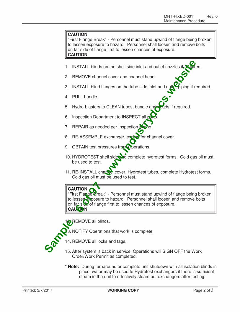
CAUTION "First Flange Break" - Personnel must stand upwind of flange being broken to lessen exposure to hazard. Personnel shall loosen and remove bolts on far side of flange first to lessen chances of exposure. CAUTION
1. INSTALL blinds on the shell side inlet and outlet nozzles if required. 2. REMOVE channel cover and channel head. 3. INSTALL blind flanges on the tube side inlet and outlet piping if required. 4. PULL bundle. 5. Hydro-blasters to CLEAN tubes, bundle and heads if required. 6. Inspection Department to INSPECT all parts. 7. REPAIR as needed per Inspection Memo. 8. RE-ASSEMBLE exchanger, except for channel cover. 9. OBTAIN test pressures from Operations. 10. HYDROTEST shell side and complete hydrotest forms. Cold gas oil must
be used to test. 11. RE-INSTALL channel cover, Hydrotest tubes, complete Hydrotest forms.
Cold gas oil must be used to test.
CAUTION "First Flange Break" - Personnel must stand upwind of flange being broken to lessen exposure to hazard. Personnel shall loosen and remove bolts on far side of flange first to lessen chances of exposure. CAUTION
12. REMOVE all blinds. 13. NOTIFY Operations that work is complete. 14. REMOVE all locks and tags. 15. After system is back in service, Operations will SIGN OFF the Work
Order/Work Permit as completed. * Note: During turnaround or complete unit shutdown with all isolation blinds in
place, water may be used to Hydrotest exchangers if there is sufficient steam in the unit to effectively steam out exchangers after testing.
Sam
ple
− 6
of 9
7 −
ww
w.in
dust
rydocs.
websi
te
MNT-FIXED-001 Rev. 0 Maintenance Procedure
Printed: 3/7/2017 WORKING COPY Page 3 of 3
END
Sam
ple
− 6
of 9
7 −
ww
w.in
dust
rydocs.
websi
te
MNT-INSP-001 Rev. 0 Inspection Procedure
INSPECTION PROCEDURE FOR SHELL AND TUBE HEAT EXCHANGERS
Printed: 3/7/2017 CONTROL COPY Page 1 of 7
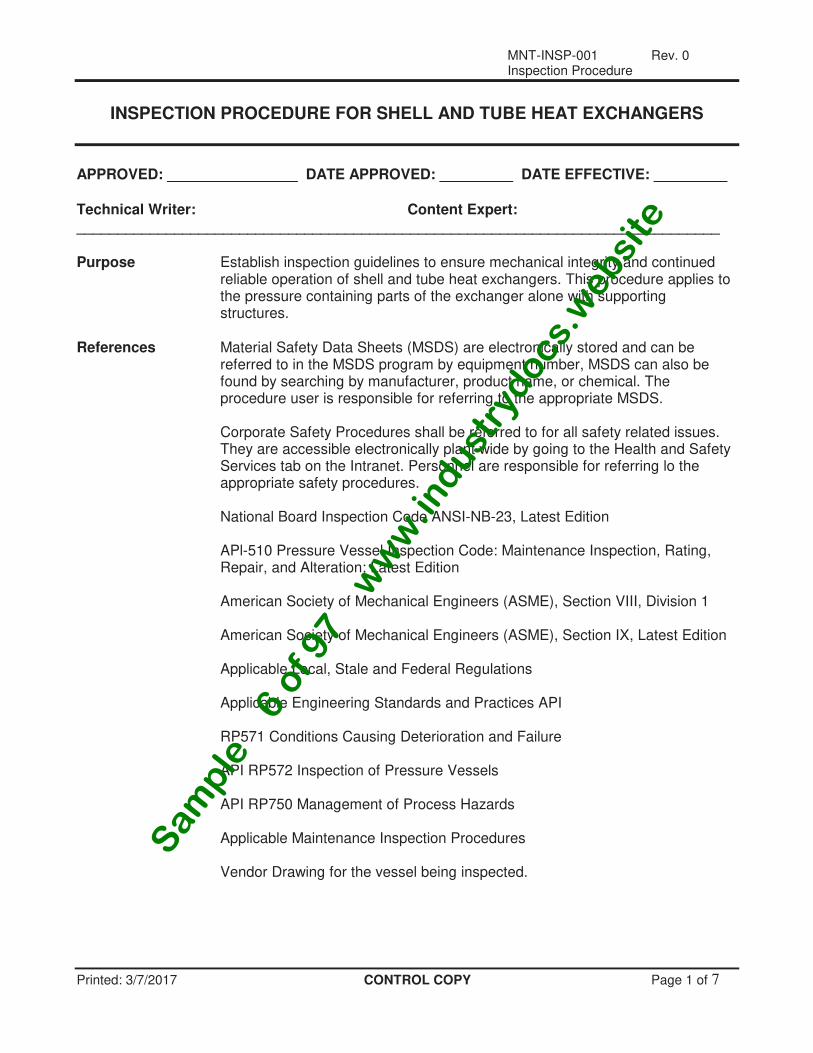
APPROVED: ________________ DATE APPROVED: _________ DATE EFFECTIVE: _________ Technical Writer: Content Expert: _______________________________________________________________________________ Purpose Establish inspection guidelines to ensure mechanical integrity and continued
reliable operation of shell and tube heat exchangers. This procedure applies to the pressure containing parts of the exchanger alone with supporting structures.
References Material Safety Data Sheets (MSDS) are electronically stored and can be
referred to in the MSDS program by equipment number, MSDS can also be found by searching by manufacturer, product name, or chemical. The procedure user is responsible for referring to the appropriate MSDS. Corporate Safety Procedures shall be referred to for all safety related issues. They are accessible electronically plant wide by going to the Health and Safety Services tab on the Intranet. Personnel are responsible for referring lo the appropriate safety procedures. National Board Inspection Code ANSI-NB-23, Latest Edition APl-510 Pressure Vessel Inspection Code: Maintenance Inspection, Rating, Repair, and Alteration; Latest Edition American Society of Mechanical Engineers (ASME), Section VIII, Division 1 American Society of Mechanical Engineers (ASME), Section IX, Latest Edition Applicable Local, Stale and Federal Regulations Applicable Engineering Standards and Practices API RP571 Conditions Causing Deterioration and Failure API RP572 Inspection of Pressure Vessels
API RP750 Management of Process Hazards Applicable Maintenance Inspection Procedures
Vendor Drawing for the vessel being inspected.
Sam
ple
− 6
of 9
7 −
ww
w.in
dust
rydocs.
websi
te
MNT-INSP-001 Rev. 0 Inspection Procedure
INSPECTION PROCEDURE FOR SHELL AND TUBE HEAT EXCHANGERS
Printed: 3/7/2017 CONTROL COPY Page 2 of 7
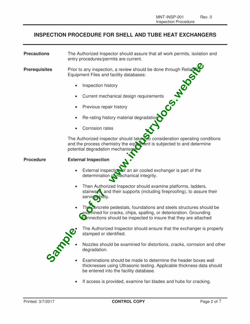
Precautions The Authorized Inspector should assure that all work permits, isolation and entry procedures/permits are current.
Prerequisites Prior to any inspection, a review should be done through Reliability
Equipment Files and facility databases:
• Inspection history
• Current mechanical design requirements
• Previous repair history
• Re-rating history material degradation
• Corrosion rates
The Authorized inspector should take into consideration operating conditions and the process chemistry the equipment is subjected to and determine potential degradation mechanisms.
Procedure External Inspection
• External inspection of an air cooled exchanger is part of the determination of mechanical integrity.
• Then Authorized Inspector should examine platforms, ladders, stairways, and their supports (including fireproofing), to assure their serviceability.
• The concrete pedestals, foundations and steels structures should be examined for cracks, chips, spalling, or deterioration. Grounding connections should be inspected to insure that they are attached
• The Authorized Inspector should ensure that the exchanger is properly stamped or identified.
• Nozzles should be examined for distortions, cracks, corrosion and other degradation.
• Examinations should be made to determine the header boxes wall thicknesses using Ultrasonic testing. Applicable thickness data should be entered into the facility database.
• If access is provided, examine fan blades and hubs for cracking.
Sam
ple
− 6
of 9
7 −
ww
w.in
dust
rydocs.
websi
te
MNT-INSP-001 Rev. 0 Inspection Procedure
INSPECTION PROCEDURE FOR SHELL AND TUBE HEAT EXCHANGERS
Printed: 3/7/2017 CONTROL COPY Page 3 of 7
• Examine hold down bolting arrangement-slots should be free of material that would restrict thermal growth.
Procedure Inspection Intervals Inspection intervals for Shell and Tube exchangers will be in accordance with
pressure vessels as defined in API 510 Vessel Inspection Code, Generally, this means inspection at vessel half remaining life, up to a maximum of ten years. Same Code also provides for extensions based on historical findings.
External Inspection intervals for Shell and Tube Exchangers will be in
accordance with pressure vessels as defined in API 510 Vessel Inspection Code. Generally, this interval is 5 years.
Internal Inspection
NOTE: The below scopes for Internal and external Inspection should not be considered the limits of inspection. Inspector is responsible for inspecting in accordance with and on the basis of referenced Code Documents.
Internal Inspections should be performed by or under the directions of an
Authorized Inspector as defined by Code. An External Inspection should be performed in conjunction with each Internal Inspection.
• The Inspector should examine the internal walls of the shell, channel and nozzles for cracking, pitting, general corrosion and erosion. Indications should be quantified through use of pit depth gages, or ultrasonics (straight or angle beam). Locations and depths should be plotted on an equipment drawing
• Scale buildup or sludge deposits should be noted along with their location on the shell or nozzle.
• All gasket surfaces should be examined for any signs of damage.
• Examine condition of pass partition plate and weldments (typically for cracking) and gasket surfaces for metal loss.
• When the tube bundle is removed from the shell, a visual examination should be done before cleaning noting the amount of scale, sludge and general fouling products. Also, if variations of deposits exist, note locations.
Sam
ple
− 6
of 9
7 −
ww
w.in
dust
rydocs.
websi
te
MNT-INSP-001 Rev. 0 Inspection Procedure
INSPECTION PROCEDURE FOR SHELL AND TUBE HEAT EXCHANGERS
Printed: 3/7/2017 CONTROL COPY Page 4 of 7
• Baffles and tie-rods should be examined for loose nuts as well as metal loss. Also check for tube OD wear where the pass through baffles.
• Verify proper location of impingement plate and for tube OD erosion in the vicinity of inlet nozzles.
• After the bundle is cleaned, a thorough examination should be performed on tubes, tube ends and tube sheets for pitting, thinning and general corrosion. A representative portion of the above should be measured using appropriate instruments. Data should include ID and OD tube measurements, and pit depths. Findings should be noted on equipment drawing.
Internal Lining Inspection
• Metallic and nonmetallic linings (e.g. strip and plate linings, overlays, internal coatings, refractory) shall be examined during internal inspections of pressure vessels.
• The inspection scope and methods recommended in API RP 572 for metallic and nonmetallic linings should be followed to assess the condition of the lining and the vessel surface beneath.
• A visual inspection of the accessible internal lining should take place at each internal inspection interval. The lining should be inspected for damage such as separation, bulging, spalling, holes, blisters, cracks, chipping, and erosion.
• If lining damage is detected, representative portions of the internal liner should be removed to assess the condition/effectiveness of the liner and the metal beneath the lining. Alternatively, ultrasonic scanning from the external surface may be used to asses the damage beneath the lining,
• Thermography (IR) is an accepted on-stream inspection method to detect refractory damage. Reference Maintenance Procedure; MNT-INSP-029. Infrared.
External Inspection The following items should be included among those Items checked during
external Inspections:
Sam
ple
− 6
of 9
7 −
ww
w.in
dust
rydocs.
websi
te
MNT-INSP-001 Rev. 0 Inspection Procedure
INSPECTION PROCEDURE FOR SHELL AND TUBE HEAT EXCHANGERS
Printed: 3/7/2017 CONTROL COPY Page 5 of 7
NOTE: It is preferred that an External Inspection Checklist is utilized for recording the results.
• Platforms, ladders, stairways, and their supports, to assure their serviceability.
• Concrete pedestals, foundations, skirt fire proofing should be examined for cracks, chips, spalling, or deterioration. Grounding connections should be inspected to insure that they are attached.
• Paint coating should be examined for blister and chipping that would expose the vessel to corrosive elements Insulation and metal jacketing should be examined for integrity of sealing and for indications of corrosion under insulation.
• Condition of Data Plates and ID Markings.
• Nozzles should be examined for distortions, cracks, corrosion, and other degradation. Reinforcements should be examined for evidence of leakage. Weep holes should be open.
• Any ancillary equipment such as level bridles, temperature or pressure gauge connections, should be inspected for external corrosion, signs of leakage, and condition of support
• The Inspector should examine the surfaces of the shells, channel covers, and heads for possible cracks, bulges, and other evidence of deterioration. Attention should be given to support saddles and other external supports.
• Follow-up examinations should be made to determine the shell and channel wall thickness (using Ultrasonic testing) in significant wall toss is observed.
Repairs and Alterations
• All repairs end alterations performed on shells, channels and heads will be done in accordance with Maintenance Procedure; MNT-INSP-015, Vessel Repair/Alteration Procedure, and in accordance to applicable Codes.
• Repairs to bundles (tube pluggings) or bundle replacements are lo be documented by the Inspector in the equipment file. Location of plugged tubes should be mapped on equipment tubesheet drawing along with date plugged.
Sam
ple
− 6
of 9
7 −
ww
w.in
dust
rydocs.
websi
te
MNT-INSP-001 Rev. 0 Inspection Procedure
INSPECTION PROCEDURE FOR SHELL AND TUBE HEAT EXCHANGERS
Printed: 3/7/2017 CONTROL COPY Page 6 of 7
• All repairs, whether to shell or bundle, are to be approved by the Reliability Authorized Inspector Maintenance Engineer should be consulted with for repairs not of a routine nature.
• Repair, alteration and bundle replacement documentation is to be kept in the Reliability Equipment Files or Plant Condition Monitoring System (PCMS).
Nonconformities
• Definition - Any change in the condition of an item described on the original Manufacturer's Data Report (U-1A), NBIC-R1 or API 510 Repair/Alterations Reports that affects the pressure containing capability of the pressure vessel.
• Non-conformance conditions will be reviewed by a designated Technical Team (typically Area Inspector and Area Maintenance Engineer) who will make repair or alteration recommendations in accordance with Maintenance Procedure; MNT-INSP-027, Inspection Recommendation Process, to assure continued integrity and Code compliance.
• Non-conformance issues should be forwarded to Refinery Management if proper resolution is not reached in a timely manner.
Reports At a minimum, condition of the following should be indicated on Inspection
Report:
1. Recommendations and Repairs Completed during current Maintenance Event.
2. Condition of the following:
a. Bundle
i. Tubes (ID and OD)
ii. Tubesheet (face a, baffle and gasket surfaces)
iii. Floating Head (ID and OD, pass partitions, gasket
surfaces)
iv. Spacers, baffles, impingement plates
Sam
ple
− 6
of 9
7 −
ww
w.in
dust
rydocs.
websi
te
MNT-INSP-001 Rev. 0 Inspection Procedure
INSPECTION PROCEDURE FOR SHELL AND TUBE HEAT EXCHANGERS
Printed: 3/7/2017 CONTROL COPY Page 7 of 7
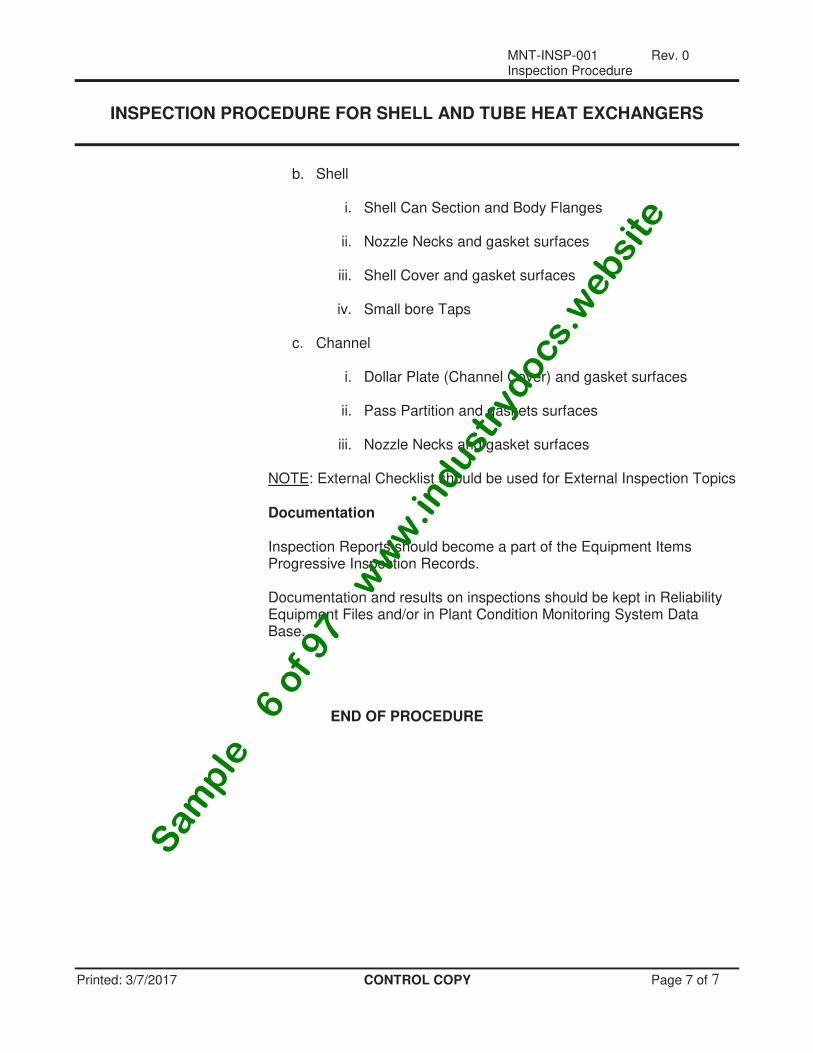
b. Shell
i. Shell Can Section and Body Flanges
ii. Nozzle Necks and gasket surfaces
iii. Shell Cover and gasket surfaces
iv. Small bore Taps
c. Channel
i. Dollar Plate (Channel Cover) and gasket surfaces
ii. Pass Partition and gaskets surfaces
iii. Nozzle Necks and gasket surfaces NOTE: External Checklist should be used for External Inspection Topics Documentation
Inspection Reports should become a part of the Equipment Items Progressive Inspection Records.
Documentation and results on inspections should be kept in Reliability
Equipment Files and/or in Plant Condition Monitoring System Data Base.
END OF PROCEDURE
Sam
ple
− 6
of 9
7 −
ww
w.in
dust
rydocs.
websi
te
MNT-MACH-001 Rev. 0 Maintenance Procedure
Printed: 3/7/2017 WORKING COPY Page 1 of 3
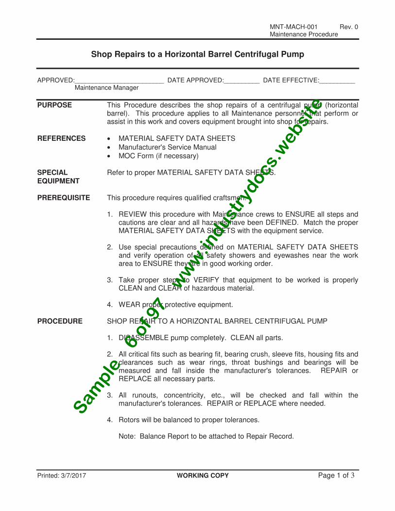
Shop Repairs to a Horizontal Barrel Centrifugal Pump
APPROVED:_________________________ DATE APPROVED:__________ DATE EFFECTIVE:__________ Maintenance Manager
PURPOSE This Procedure describes the shop repairs of a centrifugal pump (horizontal barrel). This procedure applies to all Maintenance personnel that perform or assist in this work and covers equipment brought into shop for repairs.
REFERENCES • MATERIAL SAFETY DATA SHEETS
• Manufacturer's Service Manual
• MOC Form (if necessary) SPECIAL Refer to proper MATERIAL SAFETY DATA SHEETS. EQUIPMENT PREREQUISITE This procedure requires qualified craftsmen. 1. REVIEW this procedure with Maintenance crews to ENSURE all steps and
cautions are clear and all hazards have been DEFINED. Match the proper MATERIAL SAFETY DATA SHEETS with the equipment service.
2. Use special precautions defined on MATERIAL SAFETY DATA SHEETS
and verify operation of all safety showers and eyewashes near the work area to ENSURE they are in good working order.
3. Take proper steps to VERIFY that equipment to be worked is properly
CLEAN and CLEAR of hazardous material. 4. WEAR proper protective equipment. PROCEDURE SHOP REPAIR TO A HORIZONTAL BARREL CENTRIFUGAL PUMP 1. DISASSEMBLE pump completely. CLEAN all parts. 2. All critical fits such as bearing fit, bearing crush, sleeve fits, housing fits and
clearances such as wear rings, throat bushings and bearings will be measured and fall inside the manufacturer's tolerances. REPAIR or REPLACE all necessary parts.
3. All runouts, concentricity, etc., will be checked and fall within the
manufacturer's tolerances. REPAIR or REPLACE where needed. 4. Rotors will be balanced to proper tolerances. Note: Balance Report to be attached to Repair Record.
Sam
ple
− 6
of 9
7 −
ww
w.in
dust
rydocs.
websi
te
MNT-MACH-001 Rev. 0 Maintenance Procedure
Printed: 3/7/2017 WORKING COPY Page 2 of 3
5. Any part used in a repair will be designed for the intended use and will be CHECKED for dimensional integrity, surface finish or metallurgy.
6. Any material changes must be approved by a MOC Procedure. 7. Shop will VERIFY all water jackets/coolers are CLEANED and TESTED. 8. The Manufacturer's service Manual will be used assuring that the proper
repair methods are used in the repair including specification and tolerances based on OEM specifications, industry standards or sound engineering judgment based on equipment history.
9. All pumps must be tested to VERIFY no leakage of seals, gaskets and
fittings. 10. The proper repair records will be filled out by the shop making the repairs
The facility will maintain records. Note: Final equipment alignment and piping fit ups will fall within accepted
tolerances.
END
Sam
ple
− 6
of 9
7 −
ww
w.in
dust
rydocs.
websi
te

MNT-MACH-001 Rev. 0 Maintenance Procedure
Printed: 3/7/2017 WORKING COPY Page 3 of 3
CENTRIFUGAL PUMP REPAIR RECORD
Pump #: ______________ Date: ___________ WO: _____________ Unit: ____________ Manufacturer: ____________________ RPM: __________________ Temp: ___________
1. SHAFT A. Run Out____________________ B. Coupling Fit GOOD _________ BAD _________ C. Bearing Fit 1) Thrust Bearing No. ________________ Int. Fit ________________ 2) Radial Bearing No. ________________ Int. Fit ________________ D. Throat Bushing Bushing Clearance ______________________(Max .025) Corrective Action_________________________________________________________ 2. BEARING HOUSING A. Bearing to Housing Fits 1) Thrust Bearing Clearance ____________________ 2) Radial Bearing Clearance ____________________ 3) Oil Throwers Concentricity ____________________(Max .002) B. Mic. Boss Fit 1) Bearing Housing ____________________ 2) Head ____________________ Corrective Action__________________________________________________________ 3. STUFFING BOX HEAD A. Wear Ring Clearance 1) Head Wear Ring ____________________ 2) Case Wear Ring ____________________ B. Mic. Boss Fit 1) Case Boss Fit ____________________ 2) Head Box Fit ____________________ Corrective Action___________________________________________________________ 4. Set Thrust_______________________________(Max - Packing: .003-.005 Seal: .001-.003) 5. Shaft Runout on Coup. End_________________________________(Max .002) 6. Shaft Runout on Imp. End___________________________________(Max .002) 7. Shaft Deflection________________________________(Max .002) 8. Runout from Shaft to Bearing Housing Flange Boss_________________________(Max .002) 9. Runout form Shaft to Bearing Housing Flange Face_________________________(Max .002) 10. Runout from Shaft to Head Wear Ring______________________________(Max .0035) 11. Runout on Imp.______________________________(Max .003) 12. Seal Glang Throat Center to Shaft: Yes______ No______ 13. Test Seal at_________________lbs. Test with______________________________________ 14. Date Completed_______________________________________________________________ 15. Completed by_________________________________________________________________ COMMENTS_______________________________________________________________________ __________________________________________________________________________________
Sam
ple
− 6
of 9
7 −
ww
w.in
dust
rydocs.
websi
te

MNT-RIG-001 Rev. 0 Maintenance Procedure
Printed: 3/7/2017 WORKING COPY Page 1 of 7
Choker, Wire Rope Sling, Metal Mesh Sling, Synthetic Webbing Slings, Natural and Synthetic Fiber Rope & Chain Sling Inspections
APPROVED:_________________________ DATE APPROVED:__________ DATE EFFECTIVE:__________ Maintenance Manager
PURPOSE This Procedure describes the inspections that apply to the integrity of rigging materials.
AUTHORITY The Maintenance Supervisor has the responsibility to insure compliance with
the terms of this procedure. He further has the authority to intercede, revise and/or initiate additional inspections and/or checkout requirements as may be required to insure all equipment is safe and operable and properly maintained.
REFERENCES • OSHA 1910.184
• ASME B30.9-1990
• ASME B30.9a-1991 INSPECTION FREQUENCY 1. Prior to use, the equipment shall be inspected to insure there is no
damaged or worn parts and the equipment meets or exceeds the appropriate industry standards. No record is required.
2. A semi-annual inspection shall be done to insure the equipment meets or
exceeds the appropriate industry standard. A record of this inspection will be maintained.
3. New, modified or repaired equipment shall be certified by the qualified
agency supporting or repairing the equipment. This certification record will be maintained.
SPECIAL Leather Gloves EQUIPMENT PREREQUISITE This work requires qualified craftsmen PROCEDURE WIRE ROPE SLINGS - The prior to use inspection is a visual examination by
the user or other designated personnel with records not required. These visual observations should be concerned with discovering gross damage, such as listed below, which may be an immediate hazard:
1. Distortion of rope in the sling such as kinking, crushing, unstranding,
birdcaging, main strand displacement, or core protrusion. Loss of rope diameter in short rope lengths or unevenness of outer strands should provide evidence the sling or slings should be replaced.
2. General corrosion. 3. Broken or cut strands.
Sam
ple
− 6
of 9
7 −
ww
w.in
dust
rydocs.
websi
te
MNT-RIG-001 Rev. 0 Maintenance Procedure
Printed: 3/7/2017 WORKING COPY Page 2 of 7
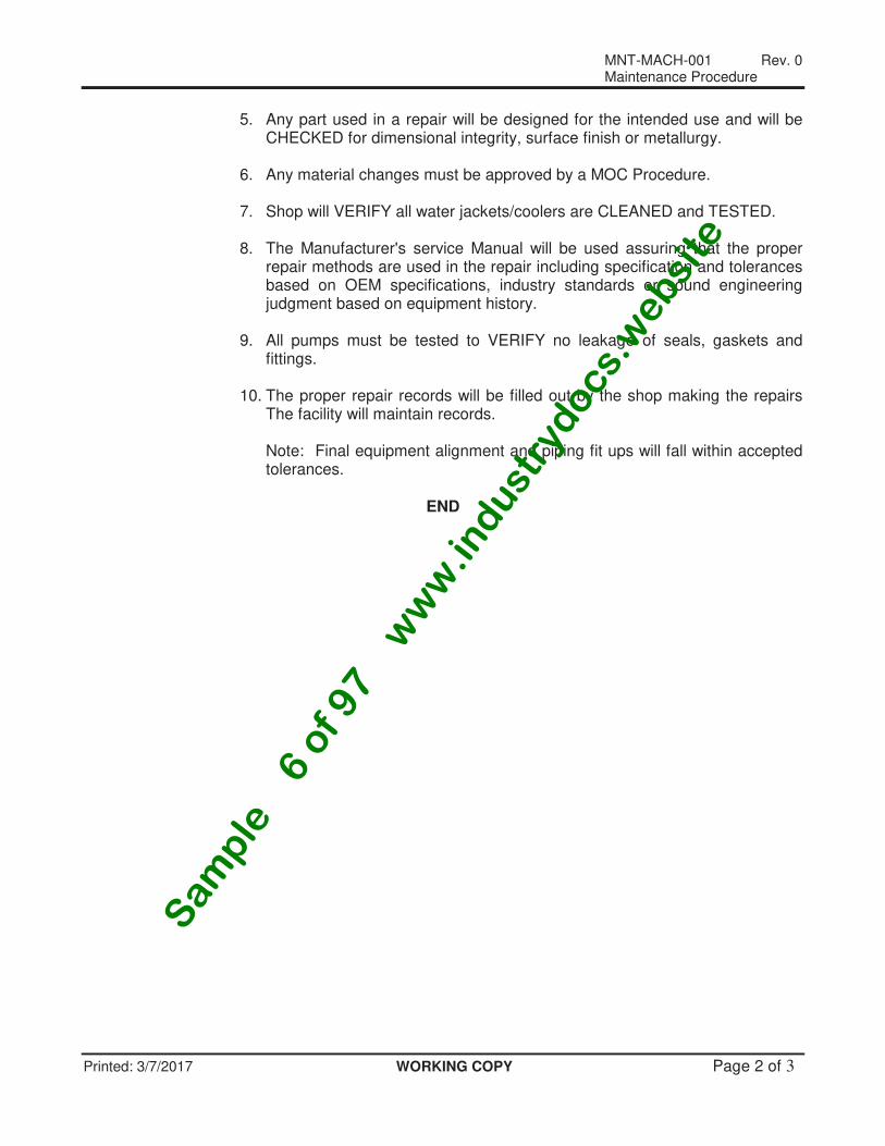
4. Number, distribution, and type of visible broken wires. 5. Examine internal rope for damage and corrosion. Semi-annual inspection - This inspection shall include the requirements listed
under prior to use inspection and, in addition, the inspection shall be conducted on the entire length of each sling including splices, end attachments, and fittings. Deterioration, which would result in loss of original strength, shall be observed and determination made whether further use of the sling would constitute a hazard.
REPLACEMENT OF WIRE ROPE SLINGS - No precise rules can be given for
determination of the exact time for replacement of a sling since many variable factors are involved. Continued use in this respect depends upon the judgment of a designated person in evaluating a used sling. Safety of sling operation depends upon this remaining strength.
Conditions such as the following should be sufficient reason for questioning
sling safety and for consideration of replacement. • For strand laid and single part slings ten randomly distributed broken wires
in one rope lay, or five broken wires in one strand in one rope lay. • Severe localized abrasion or scraping. • Kinking, crushing, birdcaging, or any other damage resulting in distortion of
the rope structure; • Evidence of heat damage. • End attachments that are cracked, deformed, or worn to the extent that the
strength of the sling is substantially affected. • Hooks should be inspected in accordance with ASME/ANSI B30.10. • Any corrosion of the rope or end attachments. • Multi-part removal criteria for cable laid and braided slings. METAL MESH SLINGS - The prior to use inspection is a visual examination by
the user or other designated personnel with records not required. It shall be inspected for safe conditions and to insure that the correct sling is being used per ASME B30.9-1990 standards.
Semi-annual inspection - This inspection shall include the requirements listed
under prior to use inspection and, in addition:
• Shall have identification giving rated load capacity in basket, choker and vertical hitch.
• A broken weld or a broken brazed joint along the sling edge. • A broken wire in any part of the mesh. • Reduction in wire diameter of 25% due to abrasion or 15% due to
corrosion. • Lack of flexibility due to distortion of the mesh. • Distortion of the choker fitting so the depth of the slot is increased by more
than 10%. • A 15% reduction of the original cross-sectional area of metal at any point
around the hook opening of end fitting.
Sam
ple
− 6
of 9
7 −
ww
w.in
dust
rydocs.
websi
te
MNT-RIG-001 Rev. 0 Maintenance Procedure
Printed: 3/7/2017 WORKING COPY Page 3 of 7
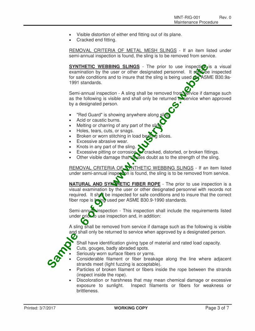
• Visible distortion of either end fitting out of its plane. • Cracked end fitting. REMOVAL CRITERIA OF METAL MESH SLINGS - If an item listed under
semi-annual inspection is found, the sling is to be removed from service. SYNTHETIC WEBBING SLINGS - The prior to use inspection is a visual
examination by the user or other designated personnel. It shall be inspected for safe conditions and to insure that the sling is being used per ASME B30.9a-1991 standards.
Semi-annual inspection - A sling shall be removed from service if damage such
as the following is visible and shall only be returned to service when approved by a designated person.
• "Red Guard" is showing anywhere along sling. • Acid or caustic burns. • Melting or charring of any part of the sling. • Holes, tears, cuts, or snags. • Broken or worn stitching in load bearing slices. • Excessive abrasive wear. • Knots in any part of the sling. • Excessive pitting or corrosion, or cracked, distorted, or broken fittings. • Other visible damage that causes doubt as to the strength of the sling. REMOVAL CRITERIA OF SYNTHETIC WEBBING SLINGS - If an item listed
under semi-annual inspection is found, the sling is to be removed from service. NATURAL AND SYNTHETIC FIBER ROPE - The prior to use inspection is a
visual examination by the user or other designated personnel with records not required. It shall be inspected for safe conditions and to insure that the correct fiber rope is being used per ASME B30.9-1990 standards.
Semi-annual inspection - This inspection shall include the requirements listed
under prior to use inspection and, in addition: A sling shall be removed from service if damage such as the following is visible
and shall only be returned to service when approved by a designated person.
• Shall have identification giving type of material and rated load capacity. • Cuts, gouges, badly abraded spots. • Seriously worn surface fibers or yarns. • Considerable filament or fiber breakage along the line where adjacent
strands meet (light fuzzing is acceptable). • Particles of broken filament or fibers inside the rope between the strands
(inspect inside the rope). • Discoloration or harshness that may mean chemical damage or excessive
exposure to sunlight. Inspect filaments or fibers for weakness or brittleness.
Sam
ple
− 6
of 9
7 −
ww
w.in
dust
rydocs.
websi
te

MNT-RIG-001 Rev. 0 Maintenance Procedure
Printed: 3/7/2017 WORKING COPY Page 4 of 7
• Kinks • Melting or charring on any part of the sling. • Excessive pitting or corrosion, or cracked, distorted or broken fittings. • Other visible damage that causes doubt as to the strength of the sling. REMOVAL CRITERIA OF FIBER SLINGS - If an item listed under semi-annual
inspection is found, the sling is to be removed from service. For additional information refer to ASME B30.9-1990. CHAIN SLINGS - The prior to use inspection is a visual examination by the
user or other designated personnel. Check: chain and attachments for wear, nicks, cracks, breaks, gouges, stretch, bends, weld splatter, discoloration from excessive temperature, and throat opening of hooks. Chain links and attachments should hinge freely with adjacent links. Latches on hook, if present, should hinge freely and seat properly without evidence of permanent distortion. Sling shall have tag giving sling length, size and rated load in vertical, basket and choker hitch.
Semi-annual inspection - this inspection shall include the requirements listed
under the prior to use inspection and in addition, items such as the following: Each link and end attachment shall be examined individually, taking care to
expose inner link surfaces of the chain and chain attachments to inspect for those items defined in ASME B30.9a-1991.
• Worn links should not exceed values given in Table 2 of ASME B30.9a-
1991 or that which is specifically recommended by the manufacturer. • Sharp transverse nicks and gouges should be rounded out by grinding and
the depth of the gouge or rounded out portion should not exceed values given in Table 2 of ASME B30.9a-1991.
• Hooks should be inspected in accordance with ASME/ANSI B30.10. • If present, latches on hooks should seat properly, rotate freely, and show
no permanent distortion. REPAIR OF CHAIN SLINGS - Any hazard condition disclosed by the
inspection requirements of ASME B30.9a-1991 shall be corrected before use of the chain or sling is resumed. Repairs shall be made only by the chain manufacturer or qualified personnel.
When repairs are made, the following criteria shall be followed:
• Certification papers to identify the length and load rating. • Alloy steel chain and coupling links used for repair shall conform to the
strength requirements and other requirements of this Standard. Cracked, broken, or bent links shall not be repaired; they shall be replaced.
• When repaired, a sling shall be permanently marked to identify the repairing agency.
Sam
ple
− 6
of 9
7 −
ww
w.in
dust
rydocs.
websi
te
MNT-RIG-001 Rev. 0 Maintenance Procedure
Printed: 3/7/2017 WORKING COPY Page 5 of 7
• Attachments which are used for repair shall conform to the strength requirements and other requirements of this Standard. Cracked, broken, or bent attachments shall not be repaired; they shall be replaced.
• Mechanical coupling links or carbon steel repair links shall not be used to repair broken lengths of alloy chain.
END
Sam
ple
− 6
of 9
7 −
ww
w.in
dust
rydocs.
websi
te
MNT-RIG-001 Rev. 0 Maintenance Procedure
Printed: 3/7/2017 WORKING COPY Page 6 of 7
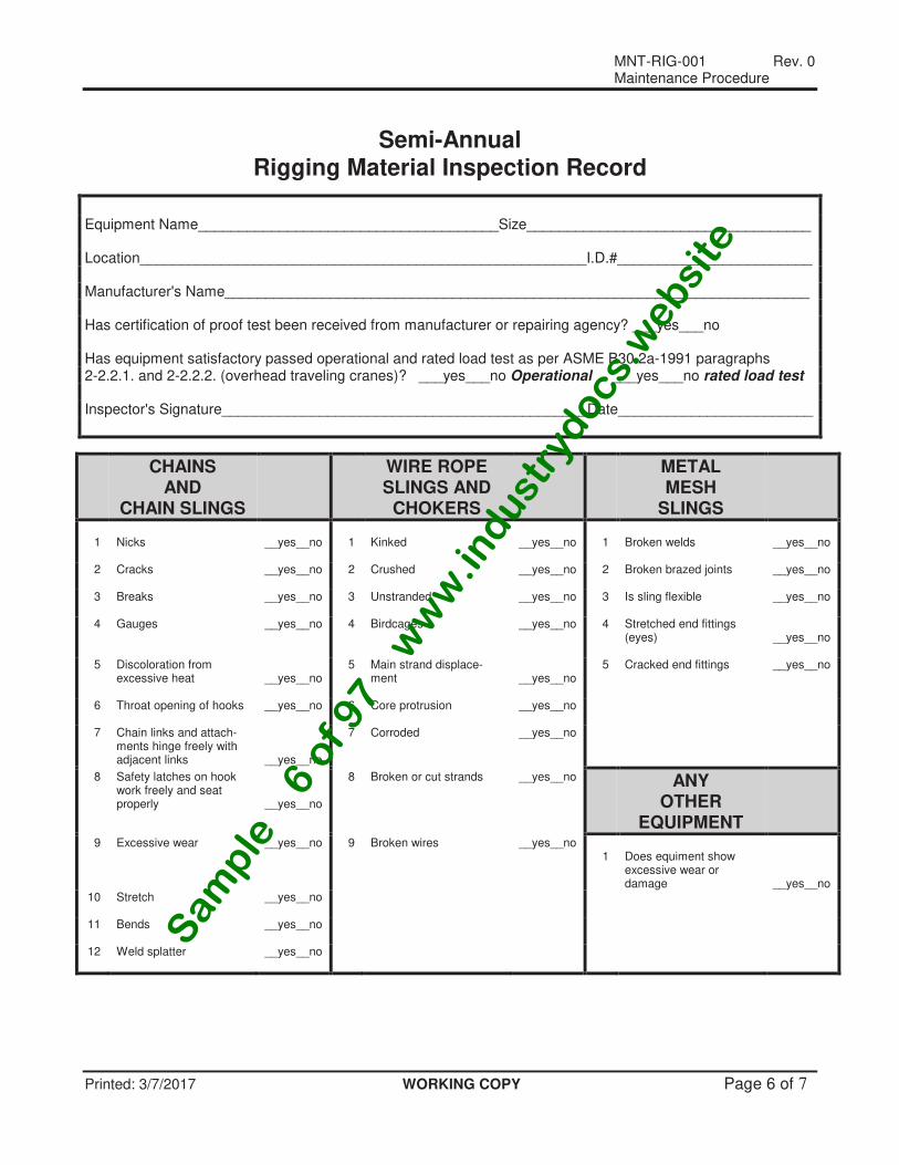
Semi-Annual Rigging Material Inspection Record
Equipment Name_____________________________________Size___________________________________ Location_______________________________________________________I.D.#________________________ Manufacturer's Name________________________________________________________________________ Has certification of proof test been received from manufacturer or repairing agency? ___yes___no Has equipment satisfactory passed operational and rated load test as per ASME B30.2a-1991 paragraphs 2-2.2.1. and 2-2.2.2. (overhead traveling cranes)? ___yes___no Operational ___yes___no rated load test Inspector's Signature_____________________________________________Date________________________
CHAINS AND
CHAIN SLINGS
WIRE ROPE SLINGS AND
CHOKERS
METAL MESH
SLINGS
1
Nicks
__yes__no
1
Kinked
__yes__no
1
Broken welds
__yes__no
2 Cracks
__yes__no 2 Crushed __yes__no 2 Broken brazed joints __yes__no
3 Breaks
__yes__no 3 Unstranded __yes__no 3 Is sling flexible __yes__no
4 Gauges __yes__no 4 Birdcages __yes__no 4 Stretched end fittings (eyes)
__yes__no
5 Discoloration from excessive heat
__yes__no
5 Main strand displace- ment
__yes__no
5 Cracked end fittings __yes__no
6 Throat opening of hooks
__yes__no 6 Core protrusion __yes__no
7 Chain links and attach- ments hinge freely with adjacent links
__yes__no
7 Corroded __yes__no
8 Safety latches on hook work freely and seat properly
__yes__no
8 Broken or cut strands __yes__no ANY OTHER
EQUIPMENT
9 Excessive wear
__yes__no 9 Broken wires __yes__no 1
Does equiment show excessive wear or damage
__yes__no
10 Stretch
__yes__no
11 Bends
__yes__no
12 Weld splatter
__yes__no
Sam
ple
− 6
of 9
7 −
ww
w.in
dust
rydocs.
websi
te
MNT-RIG-001 Rev. 0 Maintenance Procedure
Printed: 3/7/2017 WORKING COPY Page 7 of 7
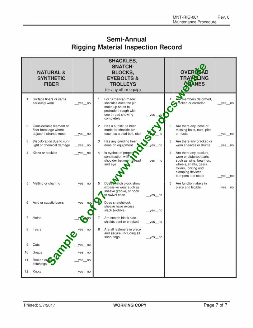
Semi-Annual Rigging Material Inspection Record
NATURAL & SYNTHETIC
FIBER
SHACKLES, SNATCH- BLOCKS,
EYEBOLTS & TROLLEYS
(or any other equip)
OVERHEAD TRAVELING
CRANES
1
Surface fibers or yarns seriously worn
__yes__no
1
For "American-made" shackles does the pin make up so as to protrude through with one thread showing completely
__yes__no
1
Are members deformed, cracked or corroded
__yes__no
2 Considerable filament or fiber breakage where adjacent strands meet
__yes__no
2 Has a substitute been made for shackle-pin (such as a stud bolt, etc)
__yes__no
2 Are there any loose or missing bolts, nuts, pins or rivets
__yes__no
3 Discoloration due to sun- light or chemical damage
__yes__no
3 Has any grinding been done on equipment
__yes__no
3 Are there any cracked or worn sheaves or drums
__yes__no
4 Kinks or hockles __yes__no 4 Is eyebolt of proper construction with shoulder between thread and eye
__yes__no
4 Are there any cracked, worn or distorted parts such as: pins, bearings, wheels, shafts, gears rollers, locking and clamping devices, bumpers and stops
__yes__no
5 Melting or charring __yes__no 5 Does snatch block show excessive wear such as sheave groove, or hook to swivel case
__yes__no
5 Are function labels in place and legible
__yes__no
6 Acid or caustic burns __yes__no 6 Does snatchblock sheave have excess slack (wobble)
__yes__no
7 Holes __yes__no 7 Are snatch block side shields bent or cracked
__yes__no
8 Tears __yes__no 8 Are all fasteners in place and secure, including all snap rings
__yes__no
9 Cuts
__yes__no
10 Snags
__yes__no
11 Broken or worn stitchings
__yes__no
12 Knots
__yes__no
Sam
ple
− 6
of 9
7 −
ww
w.in
dust
rydocs.
websi
te