Annex - R C Design Formulae and Data (2014-08-01)tycnw01.vtc.edu.hk/cbe2022/Annex - R C Design...
10
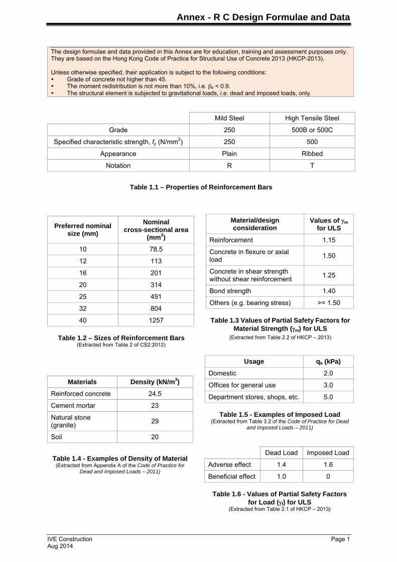
Annex - R C Design Formulae and Data IVE Construction Page 1 Aug 2014 The design formulae and data provided in this Annex are for education, training and assessment purposes only. They are based on the Hong Kong Code of Practice for Structural Use of Concrete 2013 (HKCP-2013). Unless otherwise specified, their application is subject to the following conditions: Grade of concrete not higher than 45. The moment redistribution is not more than 10%, i.e. β b < 0.9. The structural element is subjected to gravitational loads, i.e. dead and imposed loads, only. Mild Steel High Tensile Steel Grade 250 500B or 500C Specified characteristic strength, f y (N/mm 2 ) 250 500 Appearance Plain Ribbed Notation R T Table 1.1 – Properties of Reinforcement Bars Preferred nominal size (mm) Nominal cross-sectional area (mm 2 ) 10 78.5 12 113 16 201 20 314 25 491 32 804 40 1257 Table 1.2 – Sizes of Reinforcement Bars (Extracted from Table 2 of CS2:2012) Material/design consideration Values of m for ULS Reinforcement 1.15 Concrete in flexure or axial load 1.50 Concrete in shear strength without shear reinforcement 1.25 Bond strength 1.40 Others (e.g. bearing stress) >= 1.50 Table 1.3 Values of Partial Safety Factors for Material Strength ( m ) for ULS (Extracted from Table 2.2 of HKCP – 2013) Usage q k (kPa) Domestic 2.0 Offices for general use 3.0 Department stores, shops, etc. 5.0 Table 1.5 - Examples of Imposed Load (Extracted from Table 3.2 of the Code of Practice for Dead and Imposed Loads – 2011) Materials Density (kN/m 3 ) Reinforced concrete 24.5 Cement mortar 23 Natural stone (granite) 29 Soil 20 Table 1.4 - Examples of Density of Material (Extracted from Appendix A of the Code of Practice for Dead and Imposed Loads – 2011) Dead Load Imposed Load Adverse effect 1.4 1.6 Beneficial effect 1.0 0 Table 1.6 - Values of Partial Safety Factors for Load ( f ) for ULS (Extracted from Table 2.1 of HKCP – 2013)
Transcript of Annex - R C Design Formulae and Data (2014-08-01)tycnw01.vtc.edu.hk/cbe2022/Annex - R C Design...
Annex - R C Design Formulae and Data
IVE Construction Page 1 Aug 2014
The design formulae and data provided in this Annex are for education, training and assessment purposes only. They are based on the Hong Kong Code of Practice for Structural Use of Concrete 2013 (HKCP-2013). Unless otherwise specified, their application is subject to the following conditions: Grade of concrete not higher than 45. The moment redistribution is not more than 10%, i.e. βb < 0.9. The structural element is subjected to gravitational loads, i.e. dead and imposed loads, only.
Mild Steel High Tensile Steel
Grade 250 500B or 500C
Specified characteristic strength, fy (N/mm2) 250 500
Appearance Plain Ribbed
Notation R T
Table 1.1 – Properties of Reinforcement Bars
Preferred nominal size (mm)
Nominal cross-sectional area
(mm2)
10 78.5
12 113
16 201
20 314
25 491
32 804
40 1257
Table 1.2 – Sizes of Reinforcement Bars
(Extracted from Table 2 of CS2:2012)
Material/design consideration
Values of m for ULS
Reinforcement 1.15
Concrete in flexure or axial load
1.50
Concrete in shear strength without shear reinforcement
1.25
Bond strength 1.40
Others (e.g. bearing stress) >= 1.50
Table 1.3 Values of Partial Safety Factors for
Material Strength (m) for ULS (Extracted from Table 2.2 of HKCP – 2013)
Usage qk (kPa)
Domestic 2.0
Offices for general use 3.0
Department stores, shops, etc. 5.0
Table 1.5 - Examples of Imposed Load
(Extracted from Table 3.2 of the Code of Practice for Dead and Imposed Loads – 2011)
Materials Density (kN/m3)
Reinforced concrete 24.5
Cement mortar 23
Natural stone (granite)
29
Soil 20
Table 1.4 - Examples of Density of Material (Extracted from Appendix A of the Code of Practice for
Dead and Imposed Loads – 2011)
Dead Load Imposed Load
Adverse effect 1.4 1.6
Beneficial effect 1.0 0
Table 1.6 - Values of Partial Safety Factors
for Load (f) for ULS (Extracted from Table 2.1 of HKCP – 2013)

Annex - R C Design Formulae and Data
IVE Construction Page 2 Aug 2014
Elevation
h
Sw Sw
Clear Span, Ln
Effective Span, La1 = Sw/2 (if Sw < h)
a2 = h/2 (if h < Sw)
BEAM
SUPPORT 1 SUPPORT 2
Figure 1.5 - Effective Span
Limit to neutral axis x ≤ 0.5d [2.1]
The K-value K = M/(bd2fcu) [2.2]
βb = 1.0 K' = 0.156 [2.7]
βb = 0.8 K' = 0.132
Singly-reinforced section, K < K’
The lever arm z = [0.5 + (0.25 – K/0.9)0.5] d [2.3]
If K ≤ 0.0428 z = 0.95 d [2.6]
As = M / (0.87 fy z) [2.4]
Check depth of neutral axis for flanged section
(d – z) / 0.45 ≤ hf [2.11]
Doubly-reinforced section, K > K’
z = 0.775 d [2.5]
Check d' / x < 0.38 [2.10]
A's= (K – K') fcu bd2
[2.8] 0.87 fy (d - d')
As = K' fcu bd2
+ A's [2.9] 0.87 fy z
βb = moment at the section after redistribution
[1.1]moment at the section before redistribution
K 0.043 0.05 0.06 0.07 0.08 0.09 0.10 0.11 0.12 0.13 0.14 0.15 0.156
z/d 0.950 0.941 0.928 0.915 0.901 0.887 0.873 0.857 0.842 0.825 0.807 0.789 0.775
Table 2.2 – Lever Arm Factor

Annex - R C Design Formulae and Data
IVE Construction Page 3 Aug 2014
Figure 2.11 – Definition of lpi for Calculation of Effective Flange Width
(Figure 5.1 of HKCP-2013)
Figure 2.12 – Effective Flange Width (Figure 5.2 of HKCP-2013)
Elements Minimum (%) Maximum (%)
Beam
4
Flexural tension steel
Rectangular section 0.13
Flanged section (bw/b < 0.4) 0.18
Flexural compression steel
Rectangular section 0.20
Column 0.80 6
Wall
4 Vertical bars 0.40
Horizontal bars 0.25
Table 2.1 – Minimum and Maximum Percentage of Reinforcement (Grade 500)
Notes:
(a) The length of the cantilever, l3, should be less than half the adjacent span.
(b) The ratio of the adjacent spans should lie between 2/3 and 1.5.
(c) For simply-supported beam, lpi = L.
c/c distance of adjacent slabs

Annex - R C Design Formulae and Data
IVE Construction Page 4 Aug 2014
Shear Stress v = V bv = b for rectangular beam section
bv = bw for flanged beam section [3.1]
bvd
vc = 0.79 (
100 As )1/3 (
400 )1/4
1 [3.2]
bvd d m where
( 100 As
) should not be taken as greater than 3. (As is the steel area of longitudinal tension steel.) bvd
( 400
)1/4 should not be taken as less than 0.67 for members without shear reinforcement. d
( 400
)1/4 should not be taken as less than 1 for members with minimum shear reinforcement. d
m 1.25, partial factor of safety for shear strength of concrete
Table 3.1 – Values of Design Concrete Shear Stress, vc (Extracted from Table 6.3 of HKCP-2013)
If fcu > 25 MPa, the value of vc has to be multiplied by (fcu / 25)1/3.
Asv / sv ≥ bv(v – vc) / (0.87 fyv) [3.3]
Asv / sv ≥ 0.4 bv / (0.87 fyv) [3.4]
Vn = (vc + 0.4) bvd [3.5]
Max. Allowable Shear Stress = 0.8 √ fcu [3.6]
Max sv 0.75d [3.7]
Link Size Spacing of Links in (mm)
80 100 125 150 175 200 225 250 275 300 325
8 1.257 1.005 0.804 0.670 0.574 0.503 0.447 0.402 0.366 0.335 0.309
10 1.964 1.571 1.257 1.047 0.898 0.785 0.698 0.628 0.571 0.524 0.483
12 2.827 2.262 1.810 1.508 1.293 1.131 1.005 0.905 0.823 0.754 0.696
16 5.027 4.021 3.217 2.681 2.298 2.011 1.787 1.608 1.462 1.340 1.237
Table 3.23 – Asv / sv Values for Single Link (2 legs) (in mm2 per mm)
Annex - R C Design Formulae and Data
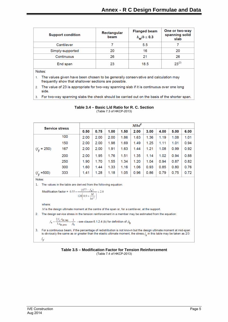
IVE Construction Page 5 Aug 2014
Table 3.4 – Basic L/d Ratio for R. C. Section (Table 7.3 of HKCP-2013)
Table 3.5 – Modification Factor for Tension Reinforcement (Table 7.4 of HKCP-2013)

Annex - R C Design Formulae and Data
IVE Construction Page 6 Aug 2014
Table 3.6 – Modification Factor for Compression Reinforcement (Table 7.5 of HKCP-2013)
At outer support
Near middle of end span
At first interior support
At middle of interior span
At interior supports
Moment 0 0.09FL -0.11FL 0.07FL -0.08FL
Shear 0.45F - 0.6F - 0.55F
Notes:
No redistribution of the moments calculated from this table should be made.
Characteristic imposed load may not exceed the characteristic dead load.
Load should be substantially uniformly distributed over three or more spans.
Variation in span length should not exceed 15% of the longest.
Table 4.1 – Force Coefficients for Continuous Beams with Approximately Equal Span under udl
(Table 6.1 of HKCP-2013)
At outer support (simply
supported)
Near middle of end span
At first interior support
At middle of interior span
At interior supports
Moment 0 0.086FL -0.086FL 0.063FL -0.063FL
Shear 0.4F - 0.6F - 0.5F
Notes:
1. Area of each bay exceeds 30 m2.
2. Characteristic imposed load does not exceed 5kPa.
3. The ratio of characteristic imposed load to the characteristic dead load does not exceed 1.25.
4. An allowance of 20% redistribution of the moments at the supports has been made.
5. Load should be substantially uniformly distributed over three or more spans.
Table 5.1 – Force Coefficients for One-way Slabs with Approximately Equal Span
under udl (Extracted from Table 6.4 of HKCP-2013)

Annex - R C Design Formulae and Data
IVE Construction Page 7 Aug 2014
Bar Size Bar Spacing in mm
100 125 150 175 200 225 250 275 300 350
8 503 402 335 287 251 223 201 183 168 144
10 785 628 524 449 393 349 314 286 262 224
12 1131 905 754 646 565 503 452 411 377 323
16 2011 1608 1340 1149 1005 894 804 731 670 574
Table 5.2 – Steel Area in mm2 per m Width
Shear and moment for simply-supported beam symmetrically loaded with two partial udl loads, w1 and w2, as shown in the figure on the right:
Shears at the supports V = w1L1 + 0.5 w2L2 [5.1]
Mid-span moment M = 0.5w1L12 + 0.5w2L2(L1 + 0.25L2) [5.2]
Effective height of a column: Le = βLo [6.1] where, Lo = The clear height between end restraints
The value of β is given in the following table:
End Condition at the
Bottom Condition 1. The end of the column is connected monolithically to beams on either side which are at least as deep as the overall dimension of the column in the plane considered. Where the column is designed to a foundation structure, this should be of a form specifically designed to carry the moment.
Condition 2. The end of the column is connected monolithically to beams on either side which are shallower than the overall dimension of the column in the plane considered.
Condition 3. The end of the column is connected to members which, while not specifically designed to provide restraint to rotation of the column will, nevertheless, provide some nominal restraint.
1 2 3
End
C
ondi
tion
at
the
Top
1 0.75 0.80 0.90
2 0.80 0.85 0.95
3 0.90 0.95 1.00
Table 6.1 – Values of β for Braced Columns (Table 6.11 of HKCP-2013)
K = Stiffness of the member
K = 4E(bh3/12)/L (for rectangular beam with fixed end)
Mes = The unbalance fixed end moment (FEM) of beams
= (FEM of b1) – (FEM of b2)
FEM = (1/12)wL2 (for beam under udl)
Mcl = Moment to the lower column
= Mes Kcl / (Kcu + Klu + 0.5Kb1 + 0.5Kb2)
Mcu = Moment to the upper column
= Mes Kcu / (Kcu + Klu + 0.5Kb1 + 0.5Kb2)
Figure 6.2 – Simplified Sub-frame Analysis for Determination of Design Moment for Column
1.0Gk 1.4G
k + 1.6Qk
Kcu
Kcl
Kb1
Kb2
w1 w1w
2
L1 L1
L2

Annex - R C Design Formulae and Data
IVE Construction Page 8 Aug 2014
Column under Axial Force
N = 0.4fcu Ac + 0.75fyAsc [6.3]
N = 0.35fcu Ac + 0.67fyAsc [6.4]
Biaxial Bending
For Mx/h' ≥ My/b', Mx' = Mx + β(h'/b')My [6.5] For Mx/h' < My/b', My' = My + β(b'/h')Mx [6.6]
N/(bhfcu) 0 0.1 0.2 0.3 0.4 0.5 ≥ 0.6
β 1.00 0.88 0.77 0.65 0.53 0.42 0.30
Table 6.2 – Values of the Coefficient β for Biaxial Bending
(Table 6.14 of HKCP-2013)

Annex - R C Design Formulae and Data
IVE Construction Page 9 Aug 2014

Annex - R C Design Formulae and Data
IVE Construction Page 10 Aug 2014
Figure 7.3 – Critical Sections for R C Design of Square Footing
Pad Footing
Column
(2) Perimeter of the column – check vmax
(1) Section across column face – design for bending
(3) Section at 1d from the column from – design for shear
(4) Perimeter at 1.5d from the column face – check punching shear
PLAN
L
a
b
c
d
e f
gh
d
1.5d
Check distribution of rebars in square footing: L ≤1.5(c+3d) [7.1]
No. of Piles
Configuration Tensile Force of the
Bottom Reinforcement
2
T = FcL/(4d)
3
T = FcL/(9d)
4
T = FcL/(8d)
Table 7.1 – Tensile Force for the Reinforcement in
Simple Pile Cap
L
L
L
L
L
L
ϕ
av
0.2ϕ
Critical section for shear check
Figure 7.5 – Critical Section for Shear Check in Pile Cap (Plan)
(Adapted from Figure 6.19 of HKCP-2013)