CON4332 REINFORCED CONCRETE DESIGNtycnw01.vtc.edu.hk/cbe2022/R2_Design Formulae for... · CON4332...
44
CON4332 REINFORCED CONCRETE DESIGN Chapter 2 1 HD in Civil Engineering (Aug 2014) │CHAPTER 2│ Design Formulae for Bending Learning Objectives Appreciate the stress-strain properties of concrete and steel for R.C. design Appreciate the derivation of the design formulae for bending Apply the formulae to determine the steel required for bending CONTENTS 2.1 Material Stress-strain Relations 2.1.1 Concrete 2.1.2 Reinforcement 2.1.3 Example – Design Ultimate Capacity for Axial Compression 2.2 Design Formulae for Bending 2.2.1 Limit to Neutral Axis 2.2.2 Examples – Effective Depth 2.2.3 Simplified Stress Block 2.2.4 Design Formulae for Singly Reinforced Section 2.2.5 Limits of the Lever Arm 2.2.6 The Balanced Section 2.2.7 Examples – Singly Reinforced Section 2.2.8 Design Formulae for Doubly Reinforced Section 2.2.9 Examples – Doubly Reinforced Section 2.3 Flanged Section 2.3.1 Effective Flange Width 1.3.2 Examples – Flanged Section 2.4 Limits to Bar Spacing and Steel Ratio 2.4.1 Bar Spacing 2.4.2 Maximum and Minimum Percentage of Steel
-
Upload
nguyenhanh -
Category
Documents
-
view
236 -
download
11
Transcript of CON4332 REINFORCED CONCRETE DESIGNtycnw01.vtc.edu.hk/cbe2022/R2_Design Formulae for... · CON4332...

CON4332 REINFORCED CONCRETE DESIGN
Chapter 2 1
HD in Civil Engineering (Aug 2014)
│CHAPTER 2│
Design Formulae for Bending
Learning Objectives
Appreciate the stress-strain properties of concrete and steel for R.C. design
Appreciate the derivation of the design formulae for bending
Apply the formulae to determine the steel required for bending
CONTENTS
2.1 Material Stress-strain Relations 2.1.1 Concrete
2.1.2 Reinforcement
2.1.3 Example – Design Ultimate Capacity for Axial Compression
2.2 Design Formulae for Bending 2.2.1 Limit to Neutral Axis
2.2.2 Examples – Effective Depth
2.2.3 Simplified Stress Block
2.2.4 Design Formulae for Singly Reinforced Section
2.2.5 Limits of the Lever Arm
2.2.6 The Balanced Section
2.2.7 Examples – Singly Reinforced Section
2.2.8 Design Formulae for Doubly Reinforced Section
2.2.9 Examples – Doubly Reinforced Section
2.3 Flanged Section 2.3.1 Effective Flange Width
1.3.2 Examples – Flanged Section
2.4 Limits to Bar Spacing and Steel Ratio 2.4.1 Bar Spacing
2.4.2 Maximum and Minimum Percentage of Steel
CON4332 REINFORCED CONCRETE DESIGN
Chapter 2 2
HD in Civil Engineering (Aug 2014)
2.1 Material Stress-strain Relations
The stress-strain curve of a material describes the deformation of the
material in response to the load acted upon it. In generalized terms,
deformation is presented in terms of change in length per unit length, i.e.
strain, while load is in terms of force per unit area, i.e. stress.
Strain, Ɛ = Deformation
(Dimensionless) Length
Stress, f = Force
(in N/mm2 or MPa) Area
The stress-strain curves of concrete and steel provides the fundamental
knowledge to understand the behaviour of the R.C. composite under loads
and for deriving the necessary formulae for R. C. design.
2.1.1 Concrete
Concrete is comparatively very weak in tension. Its tensile strength is
about 1/10 of the compressive strength. It is usually ignored in the design.
Therefore, the stress-strain curve of concrete is usually referring to concrete
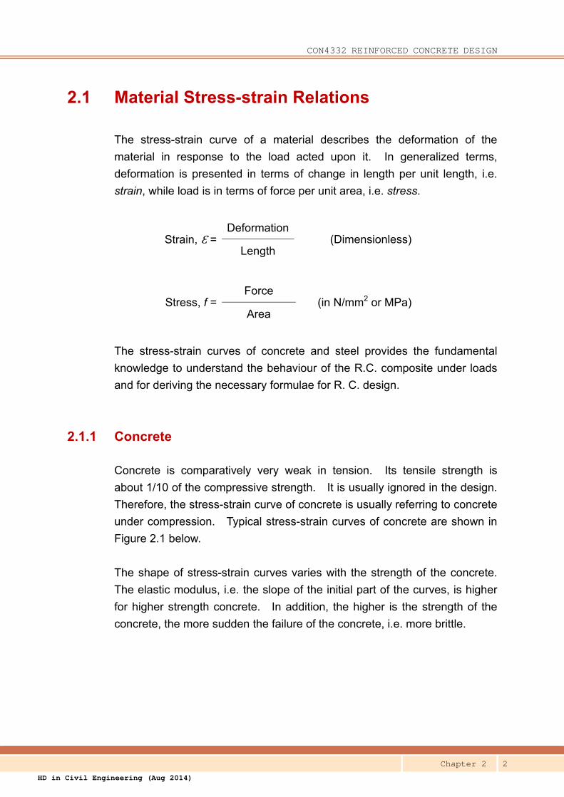
under compression. Typical stress-strain curves of concrete are shown in
Figure 2.1 below.
The shape of stress-strain curves varies with the strength of the concrete.
The elastic modulus, i.e. the slope of the initial part of the curves, is higher
for higher strength concrete. In addition, the higher is the strength of the
concrete, the more sudden the failure of the concrete, i.e. more brittle.

CON4332 REINFORCED CONCRETE DESIGN
Chapter 2 3
HD in Civil Engineering (Aug 2014)
Figure 2.1 – Typical Stress-strain Curves of Concrete
In order to facilitate the derivation of design formulae, an idealized
stress-strain curve in parabolic-rectangular shape is adopted in the design
code as shown in Figure 2.2 below.
Figure 2.2 – Idealized Stress-strain Curve of Concrete for Design
(Figure 3.8 of HKCP-2013)
Strain
Stress (MPa)
0.001 0.002 0.003 0.004 0.005
40
80
120
0

CON4332 REINFORCED CONCRETE DESIGN
Chapter 2 4
HD in Civil Engineering (Aug 2014)
Take note of the following points:
(a) The design ultimate strength of concrete is:
0.67 fcu / m = 0.67 fcu / 1.5 0.45 fcu
where
0.67 is to account for the differences between the testing
condition and the actual effect on concrete in the structure.
1.5 is the partial factor of safety for the strength of concrete
under bending or axial load.
(b) The ultimate compressive strain of concrete is:1
Ɛcu = 0.0035
The concrete crushes when it deforms to this value and the failure is
brittle and sudden. This value defines the ultimate limit state, ULS,
of R. C structure.
2.1.2 Reinforcement
Steel is much stronger and more ductile than concrete as illustrated in the
typical stress-strain curves of steel in Figure 2.3.
The initial part of the curve is linear and the slope, i.e. the elastic module, is
constant disregard of the strength. The following value of elastic modulus
is adopted in R.C. design.
Es = 200 kN/m2 or 200 000 N/m2
1 This value is for concrete not higher than Grade C60. Concrete becomes more brittle when its strength is higher,
and therefore the value of Ɛcu is lower. Details refer to the design code.

CON4332 REINFORCED CONCRETE DESIGN
Chapter 2 5
HD in Civil Engineering (Aug 2014)
Figure 2.3 – Typical Stress-strain Curves of Steel
Most of the grades of steel exhibit a definite yield point at which strain
increases suddenly without increase in stress. The stress at this point, i.e.
yield stress, fy, is adopted for design. For steel without yield, 0.2% proof
stress is adopted. Beyond this point, the strength of steel continues to
increase but with substantial increase in strain.
Steel deforms substantially before rupture, and the ultimate strength
increases by more than 8% above the yield, and the ultimate strain is more
than 0.05. This strength hardening and ductility properties render steel a
good structural material.
The tensile and compressive strength properties of steel are the same.
The design code provides an idealized stress-strain curve for design as
given in Figure 2.4.
0.04 0.08 0.12 0.16 0.20
100
200
300
400
500
600
700
800
Stress (MPa)
Strain 0
0.002
0.2% Proof
Stress
A typical stress-strain
curve of concrete
Yield Stress

CON4332 REINFORCED CONCRETE DESIGN
Chapter 2 6
HD in Civil Engineering (Aug 2014)
Figure 2.4 – Idealized Stress-strain Curve
of Reinforcement for Design
(Figure 3.9 of HKCP-2013)
Take note of the following points:
(a) The design yield strength is:
fy / m = fy / 1.15 = 0.87 fy
(b) Within the elastic range, i.e. before yield:
Stress = Es Ɛs
= 200 000 Ɛs
(c) The yield strain, i.e. beyond which the stress of steel is 0.87fy, is:
Ɛy = 0.87fy / 200 000
For grade 500 steel,
Ɛy = 0.87 x 500 / 200 000
= 0.002175
Ɛy

CON4332 REINFORCED CONCRETE DESIGN
Chapter 2 7
HD in Civil Engineering (Aug 2014)
2.1.3 Example – Design Ultimate Capacity for Axial Compression
The design ultimate capacity of a concrete section subject to axial
compression is given by Eqn 6.5 of HKCP-20132:
Nuz = Compression Resistance of Concrete
+ Compression Resistance of Steel
= 0.45 fcu Anc + 0.87 fy Asc
where
Anc = Net cross-sectional area of concrete
Asc = Area of steel in compression
Question Determine the design ultimate capacity for axial compression of the following concrete
section:
Concrete : C40
Dimensions : 400mm x 400mm
Rebars : 4T25 vertical bars fully restrained by links
Solution Asc = 4 x 491
= 1 964 mm2
Anc = 400 x 400 – 1 964
= 158 036 mm2
Nuz = 0.45 fcu Anc + 0.87 fy Asc
= (0.45 x 40 x 158036 + 0.87 x 500 x 1964) x 10-3
= 2845 + 854
= 3 699 kN
2 The application of this equation is subject to the following conditions: (i) the column is subject to axial load only,
without eccentricity and moment, (ii) the rebars restrained from buckling, and (iii) the column is not slender.
Design of column will be discussed in another chapter.

CON4332 REINFORCED CONCRETE DESIGN
Chapter 2 8
HD in Civil Engineering (Aug 2014)
2.2 Design Formulae for Bending
When a beam is under downward bending as shown in Figure 2.5 below, the
upper part of the beam is in compression and the lower part is in tension. If
the plane section remains plane after deformation as shown in figure (a), the
strain distribution will be linear as shown in figure (b), with zero strain at the
neutral axis and increasing linearly outward towards the top and bottom
fibres of the section.3
a
b
d
c
M M
a
b
d
c
Elevation of a Beam under Load
Rebar
d
x
Ɛcc
Ɛst
(a) Deformation of a-b-c-d (b) Strain (c) Stress (Elastic) (d) Stress (Plastic)
Neutral Axis
Figure 2.5 – Distribution of Stresses and Strains
across a Beam Section
When the load is small and the material is still linear elastic, the stress will be
in linear proportion to the strain. The distribution of the compressive stress
above the neutral axis is then in triangular shape as shown in figure (c).
The concrete below the neutral axis is assumed unable to take up any
tensile stress, and rebars are provided to take up the tension.
3 The "plane section remains plane" assumption is usually valid in beam design, except under some
circumstances, for examples, deep beam with span-to-depth ratio is smaller than 4, at section under very high
shear force, etc. It is out of the scope of this chapter.

CON4332 REINFORCED CONCRETE DESIGN
Chapter 2 9
HD in Civil Engineering (Aug 2014)
If the load is further increased until the section become plastic, the
compressive stress block of concrete will become parabolic in shape and the
tension steel become yielded as shown in figure (d).
2.2.1 Limits to the Neutral Axis
Considering the compatibility of strain in figure (b) above, and assuming
there no slip at the interface of concrete and steel bar, the relationship of the
maximum strain of concrete compression, Ɛcc, and the strain of steel in
tension, Ɛst, is given by:
Ɛst = Ɛcc (d – x)
x
where
d = The effective depth of the section. It is the depth
measured from the top of the section (for sagging
moment) to the centroid of the tension reinforcement.
x = The depth of the neutral axis, above which (for sagging
moment) the section is in compression while below
which the section cracks under tension.
In order to ensure ductility, it is desirable to have the tension reinforcement
yielded before the concrete crushes. That is
Ɛst ≥ 0.002175 when Ɛcc = 0.0035
Therefore, 0.0035 (d – x) ≥ 0.002175
x
Re-arranging, it becomes x ≤ 0.617 d
In other words, the section should be designed such that depth of neutral
axis should not exceed the limit to ensure ductility.

CON4332 REINFORCED CONCRETE DESIGN
Chapter 2 10
HD in Civil Engineering (Aug 2014)
3T32
h d
2T40 + T32
h d
2T32
d
Bar size / 2 Link size Cover
HKCP-2013 limits the depth of neutral axis to:4
x ≤ 0.5 d [2.1]
If moment redistribution is more than 10%, i.e. βb < 0.9, the depth of neutral
axis is limited to:
x ≤ (βb - 0.4) d [2.1a]
For example, if βb = 0.8, the limiting neutral axis is 0.4d.
2.2.2 Examples – Effective Depth
Question A Determine the effective depth of the following section:
Overall beam depth, h = 500 mm
Concrete cover = 40 mm
Size of link: 10
Bottom bars: 3T32 in one layer
Solution Effective Depth, d = 500 – 40 – 10 – 32/2
= 434 mm
Question B Determine the effective depth of the following section:
Overall beam depth, h = 650 mm
Concrete cover = 45 mm
Size of link: 12
Bottom bars: 2T40 + 3T32 in two layers
4 This limit is for concrete not higher than Grade C45. For higher grade of concrete the limit is more stringent.
Details refer to the design code.

CON4332 REINFORCED CONCRETE DESIGN
Chapter 2 11
HD in Civil Engineering (Aug 2014)
Solution The clear spacing between two layers of bars should not be less than (vide Cl.8.2 of
HKCP-2013):
(a) maximum bar size
(b) aggregate size + 5 mm
(c) 20 mm
In this case, the maximum bar size controls, i.e. 40mm.
Distance to the bottom T40 = 650 – 45 – 12 – 20 = 573 mm
Distance to the bottom T32 = 650 – 45 – 12 – 16 = 577 mm
Distance to the 2nd layer T32 = 650 – 45 – 12 – 40 – 40 - 16 = 497 mm
Effective Depth, d =1257 x 2 x 573 + 804 x 577 + 804 x 2 x 497
1257 x 2 + 804 x 3
= 549 mm
Alternatively, the effective depth is simply taken to the "center", instead of the centroid, of
the two layers of rebars as follows.
Effective depth, d = 650 – 45 – 12 – 40 – 20
= 533 mm (the deviation is about 2.9% only)
Unless rigorous checking is required, this method is in general acceptable for manual
calculation in design office. In fact, during the initial design stage, the amount steel
required is unknown. Assumption has to be made on the bar size, based on which to
estimate the effective depth for calculating the steel required and then the number and size
of bars. Once the bar size is known, the initial assumption on effective depth has to
verified. If the initial assumption is on conservative side and does not deviate too much
from actual value, the result will then be treated as acceptable and the calculation would not
be re-done.
2.2.3 Simplified Stress Block
After the steel has yielded, the beam continues to deform until the top
concrete crushes at the ultimate strain, Ɛcu, and the distribution of
compressive stress in the compression zone, i.e. above the neutral axis, will
then be in the shape of rectangular-parabolic as shown in (b) of Figure 2.6
below. In order to make it more manageable in deriving the design formula
for bending, a simplified rectangular stress block as shown figure (c) of
Figure 2.6 is adopted (Figure 6.1 of HKCP-2013).
?Q.1 – Q.4

CON4332 REINFORCED CONCRETE DESIGN
Chapter 2 12
HD in Civil Engineering (Aug 2014)
Ɛcu
Ɛst
(a) Strain at Ultimate
Limit State
(b) Parabolic Stress
Block
Section
0.45fcu
d
x
0.45fcu
s s/2
z
(c) Simplified Rectangular
Stress Block
Neutral Axis
Figure 2.6 – Stress and Strain Distribution at Ultimate Limit State
In the simplified stress block, a uniform compressive stress of
0.67 fcu / m = 0.45fcu is adopted over a depth of:5
s = 0.9 x
and, the lever arm, z, between the centroid of the compression force in the
concrete and the tension force of rebars is:
z = d – s/2
Rearranging, s = 2(d – z)
2.2.4 Design Formulae for Singly-Reinforced Section
The objective of the design formulae is to determine the steel area, As, with
the following information given:
The design ultimate moment: M
5 It is for concrete not higher than Grade C45. The value of "s" is smaller for higher grade of concrete. Details
refer to the design code.

CON4332 REINFORCED CONCRETE DESIGN
Chapter 2 13
HD in Civil Engineering (Aug 2014)
Grade of concrete : fcu
Grade of steel : fy
Breadth of section : b
Effective depth : d
Section
d
x
0.45fcu
s =
0.9
x
s/2
z
Simplified Rectangular Stress Block
Neutral Axis
As
Fcc
Fst
M
b
Figure 2.7 – Simplified Stress Block for R.C. Design
Compression in concrete Fcc = 0.45 fcu (b s)
= 0.9 fcu b (d - z)
Tension in the rebar Fst = 0.87 fy As
Take moment about the rebar, and by equilibrium of moment:
M = Fcc z
= 0.9 fcu b (d - z) z
Divide both sides by (bd2fcu), and
let K = M/(bd2fcu) [2.2]
the equation becomes:

CON4332 REINFORCED CONCRETE DESIGN
Chapter 2 14
HD in Civil Engineering (Aug 2014)
(z/d)2 – (z/d) + K/0.9 = 0
Solve for z/d, the level arm factor:
z/d = [0.5 + (0.25 – K/0.9)0.5]
and then, the level arm: z = [0.5 + (0.25 – K/0.9)0.5] d [2.3]
This is Eqn 6.10 of HKCP-2013.
Take moment about the centroid of the compression force, and by
equilibrium of moment:
M = Fst z
= 0.87 fy As z
Rearranging, As = M / (0.87 fy z) [2.4]
This is Eqn 6.12 of HKCP-2013.
2.2.5 Limits of the Lever Arm, z
The limit to the depth of neutral axis, i.e. x ≤ 0.5 d, imposes a lower limit to
the lever arm6:
z ≥ d – 0.9(0.5d) / 2
z ≥ 0.775 d [2.5]
If moment redistribution is more than 10%, i.e. βb < 0.9
z ≥ (1.18 – 0.45βb) d [2.5a]
6 This limit is for concrete not higher than Grade 45. This limit is more stringent for higher grade of concrete.
Refer to the design code for details.
CON4332 REINFORCED CONCRETE DESIGN
Chapter 2 15
HD in Civil Engineering (Aug 2014)
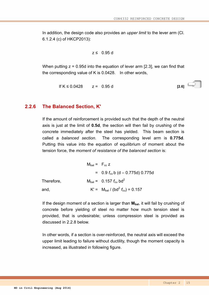
In addition, the design code also provides an upper limit to the lever arm (Cl.
6.1.2.4 (c) of HKCP2013):
z ≤ 0.95 d
When putting z = 0.95d into the equation of lever arm [2.3], we can find that
the corresponding value of K is 0.0428. In other words,
If K ≤ 0.0428 z = 0.95 d [2.6]
2.2.6 The Balanced Section, K'
If the amount of reinforcement is provided such that the depth of the neutral
axis is just at the limit of 0.5d, the section will then fail by crushing of the
concrete immediately after the steel has yielded. This beam section is
called a balanced section. The corresponding level arm is 0.775d.
Putting this value into the equation of equilibrium of moment about the
tension force, the moment of resistance of the balanced section is:
Mbal = Fcc z
= 0.9 fcu b (d – 0.775d) 0.775d
Therefore, Mbal = 0.157 fcu bd2
and, K' = Mbal / (bd2 fcu) = 0.157
If the design moment of a section is larger than Mbal, it will fail by crushing of
concrete before yielding of steel no matter how much tension steel is
provided, that is undesirable; unless compression steel is provided as
discussed in 2.2.8 below.
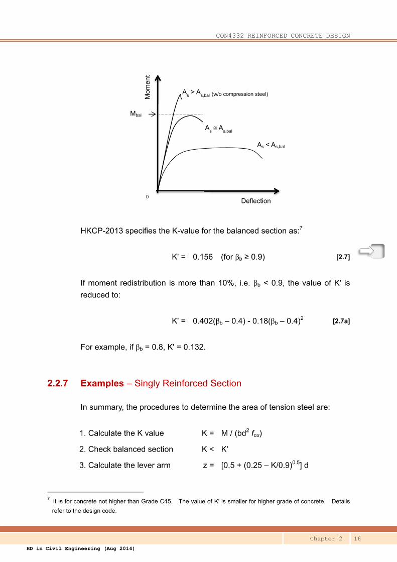
In other words, if a section is over-reinforced, the neutral axis will exceed the
upper limit leading to failure without ductility, though the moment capacity is
increased, as illustrated in following figure.
CON4332 REINFORCED CONCRETE DESIGN
Chapter 2 16
HD in Civil Engineering (Aug 2014)
HKCP-2013 specifies the K-value for the balanced section as:7
K' = 0.156 (for βb ≥ 0.9) [2.7]
If moment redistribution is more than 10%, i.e. βb < 0.9, the value of K' is
reduced to:
K' = 0.402(βb – 0.4) - 0.18(βb – 0.4)2 [2.7a]
For example, if βb = 0.8, K' = 0.132.
2.2.7 Examples – Singly Reinforced Section
In summary, the procedures to determine the area of tension steel are:
1. Calculate the K value K = M / (bd2 fcu)
2. Check balanced section K < K'
3. Calculate the lever arm z = [0.5 + (0.25 – K/0.9)0.5] d
7 It is for concrete not higher than Grade C45. The value of K' is smaller for higher grade of concrete. Details
refer to the design code.
Deflection
Mom
ent
0
Mbal
As < As,bal
As A
s,bal
As > A
s,bal (w/o compression steel)

CON4332 REINFORCED CONCRETE DESIGN
Chapter 2 17
HD in Civil Engineering (Aug 2014)
4. Check z / d ≤ 0.95
5. Calculate the steel area As = M / (0.87 fy z)
Question A Determine the rebars for the following beam section:
Design ultimate moment, M = 350 kN-m βb = 1.0
Breadth, b = 350 mm
Effective depth, d = 480 mm
Concrete, fcu = 35 MPa
Steel, fy = 500 MPa
Solution K = M / (bd2 fcu)
= 350 x 106 / (350 x 4802 x 35)
= 0.124
βb = 1.0 < 0.156 (Singly reinforced)
Lever arm, z = [0.5 + (0.25 – K/0.9)0.5] d
= [0.5 + (0.25 – 0.124/0.9)0.5] x 480
= 0.835 x 480
= 401 mm
Tension steel req'd, As = M / (0.87 fy z)
= 350 x 106 / (0.87 x 500 x 401)
= 2 006 mm2
(Provide 2T32 + 1T25)
As,pro = 2 x 804 + 491
= 2099 mm2
Question B For the section in Example A, find the moment of resistance of the balanced section and the
corresponding amount of steel.
Solution Mbal = K' fcu bd2

CON4332 REINFORCED CONCRETE DESIGN
Chapter 2 18
HD in Civil Engineering (Aug 2014)
Simplified Rectangular Stress Block
d
x
0.45fcu
s =
0.9
x
s/2
z
N.A.
Fcc
Fst
M
= 0.156 x 35 x 350 x 4802 x 10-6
= 440 kN-m
z = 0.775 d
= 0.775 x 480
= 372 mm
As = M / (0.87 fy z)
= 440 x 106 / (0.87 x 500 x 372)
= 2719 mm2
Question C Determine the ultimate moment of resistance of the following beam section:
Breadth, b = 350 mm
Effective depth, d = 480 mm
Area of steel provided, As = 2412 mm2 (i.e. 3T32)
Concrete, fcu = 35 MPa
Steel, fy = 500 MPa
Solution (The design formulae in the design
code are given in the form to facilitate
the determination of steel area from
the design moment. This example,
however, requires you to work back
the ultimate moment capacity of the
section from the steel area provided.)
For equilibrium of compression and tension forces:
Fcc = Fst
0.45 fcu (b s) = 0.87 fy As (assuming steel has yielded)
s = 0.87 fy As / (0.45 fcu b)
= 0.87 x 500 x 2412 / (0.45 x 35 x 350)
= 190.3 mm
Depth of neutral axis, x = s / 0.9
= 190.3 / 0.9

CON4332 REINFORCED CONCRETE DESIGN
Chapter 2 19
HD in Civil Engineering (Aug 2014)
= 211.5 mm
< 0.5 x 480 = 240 mm (steel has yielded as assumed)
Lever arm, z = d – s/2
= 480 – 190.3 / 2
= 384.9 mm
Take moment about the centroid of compression zone:
Moment of resistance, M = Fst z
= 0.87 fy As z
= 0.87 x 500 x 2412 x 384.9 x 10-6
= 404 kN-m
2.2.8 Design Formulae for Doubly Reinforced Section
When the design moment becomes so large that
K > K',
compression reinforcement is required to provide additional compressive
resistance in the compression zone of the section. If the area of
compression steel, A's, is located at d' from the top of the section as shown
in Figure 2.8, the formulae for determining As and A's are derived as follows.
The neutral axis cannot be further lowered. It remains at the limiting depth
to retain ductility. Therefore,
z = (1.18 – 0.45βb) d
Fcc z = K' fcu bd2
For βb < 0.9,
z = 0.775 d
Fcc z = 0.156 fcu bd2
?Q.5 – Q.8

CON4332 REINFORCED CONCRETE DESIGN
Chapter 2 20
HD in Civil Engineering (Aug 2014)
Section
Ɛcu
Ɛst
(a) Strain at Ultimate Limit
State
d
x
0.45fcu
s
z =
d –
s/2
(b) Simplified Rectangular
Stress Block
Neutral Axis
d'
Ɛsc
d –
d'
As
As'
Fst
Fcc
Fsc
M
Figure 2.8 – Stress and Strain Distribution
for Doubly Reinforced Section
Compression in the compression reinforcement:
Fsc = fsc A's
where fsc = stress in the compression steel
Take moment about the tension steel, and by equilibrium of moment:
M = Fcc z + Fsc (d - d')
= 0.156 fcu bd2 + fsc A's (d - d')
Rearranging, it becomes
A's =M - 0.156 fcu bd2
fsc (d - d')

CON4332 REINFORCED CONCRETE DESIGN
Chapter 2 21
HD in Civil Engineering (Aug 2014)
or A's =(K – K') fcu bd2
[2.8a]fsc (d - d')
By equilibrium of forces
Fst = Fcc + Fsc
0.87 fy As = 0.156 fcu bd2 / z + fsc As'
Rearranging, it becomes
As =0.156 fcu bd2
+ As' fsc
0.87 fy z 0.87 fy
or As =K' fcu bd2
+ As' fsc
[2.9a]0.87 fy z 0.87 fy
The value of fsc can be determined from the strain distribution in Figure 2.8(a)
above, that is
Ɛsc / (x - d') = Ɛcu / x
Rearranging, d' / x = 1 - Ɛsc / Ɛcu
If Ɛsc > 0.002175 at Ɛcu = 0.0035, the compression steel has yielded at the
ultimate limit state, i.e. fsc = 0.87 fy :
In other words, if d' / x < 1 – 0.002175 / 0.0035 = 0.38 [2.10]
A's=(K – K') fcu bd2
[2.8]0.87 fy (d - d')
and, As =K' fcu bd2
+ A's [2.9]0.87 fy z
These are Eqns 6.14 and 6.15 in HKCP-2013.
On the other hand,
CON4332 REINFORCED CONCRETE DESIGN
Chapter 2 22
HD in Civil Engineering (Aug 2014)
if d' / x > 0.38
the compression bars are so close to the neutral axis that they has not
yielded and the stress in the compression bars has to be calculated by:
fsc = Es Ɛsc
2.2.9 Examples – Doubly Reinforced Section
In summary, the procedures to determine the steel areas for doubly
reinforced section are (for βb > 0.9):
1. Provide comp'n steel, if K > 0.156
2. Calculate the lever arm z = 0.775d
3. Calculate the neutral axis x = 0.5d
4. Check d' / x ≤ 0.38 to ensure rebar has yielded
5. Calculate compression steel A's=(K – K') fcu bd2
0.87 fy (d - d')
6. Calculate tension steel As =K' fcu bd2
+ A's 0.87 fy z
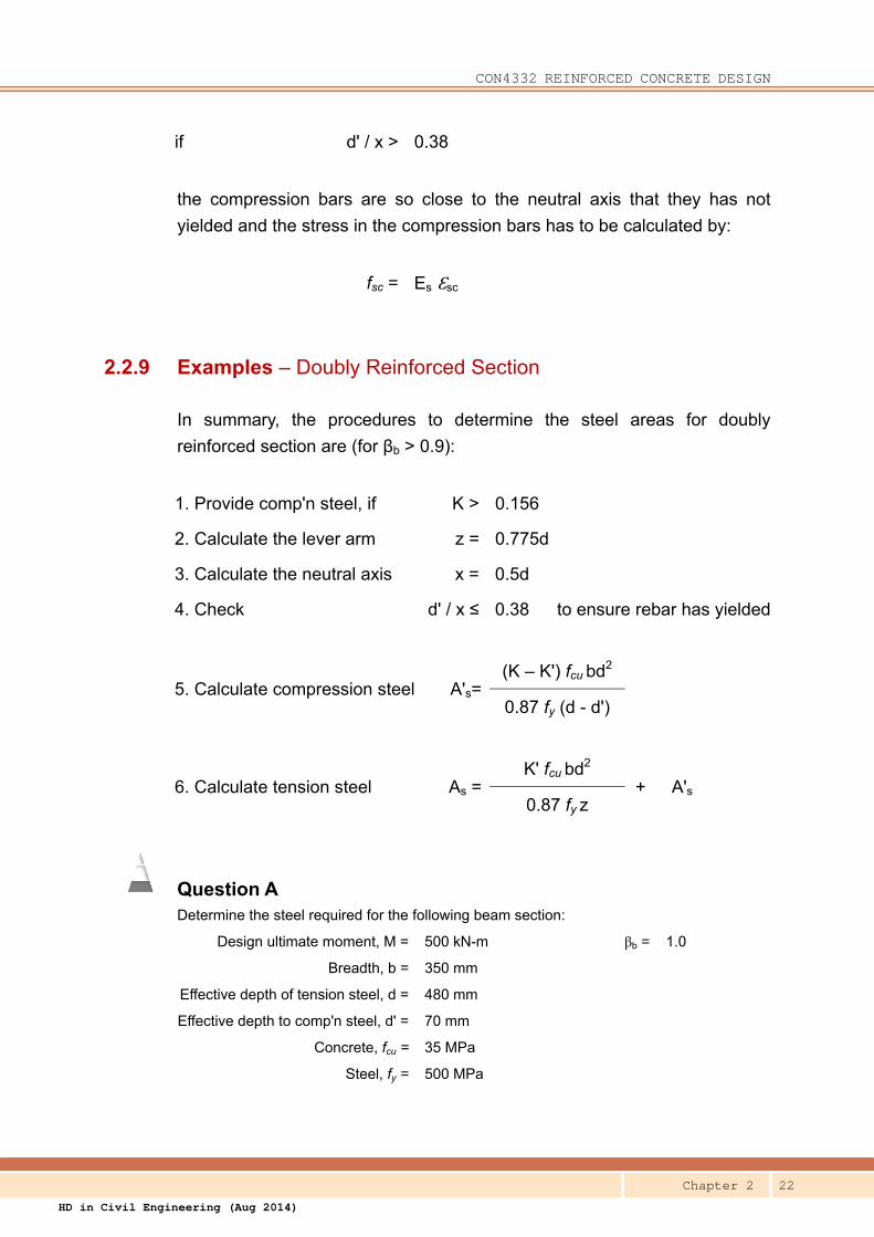
Question A Determine the steel required for the following beam section:
Design ultimate moment, M = 500 kN-m βb = 1.0
Breadth, b = 350 mm
Effective depth of tension steel, d = 480 mm
Effective depth to comp'n steel, d' = 70 mm
Concrete, fcu = 35 MPa
Steel, fy = 500 MPa

CON4332 REINFORCED CONCRETE DESIGN
Chapter 2 23
HD in Civil Engineering (Aug 2014)
Solution K = M / (bd2 fcu)
= 500 x 106 / (350 x 4802 x 35)
= 0.177
βb =1.0 > 0.156 (Compression steel is required)
Lever arm, z = 0.775 d
= 0.775 x 480
= 372 mm
Depth to neutral axis, x = 0.5 d
= 0.5 x 480
= 240 mm
Check d' / x = 70 / 240
= 0.29 < 0.38 (fsc = 0.87fy)
Compression steel req'd, A's =(K – K') fcu bd2
0.87 fy (d - d')
=(0.177 – 0.156) x 35 x 350 x 4802
0.87 x 500 x (480 – 70)
= 332 mm2
(Provide 2T16 Top Bars)
A's,pro = 2 x 201
= 402 mm2
Tension steel req'd, As =K' fcu bd2
+ As' 0.87 fy z
=0.156 x 35 x 350 x 4802
+ 332 0.87 x 500 x 372
= 2721 + 332
= 3053 mm2
(Provide 4 T32 Bottom Bars)
As, pro = 4 x 804
= 3216 mm2
CON4332 REINFORCED CONCRETE DESIGN
Chapter 2 24
HD in Civil Engineering (Aug 2014)
d
x
Neutral Axis
d' Ɛ
sc
Ɛcu
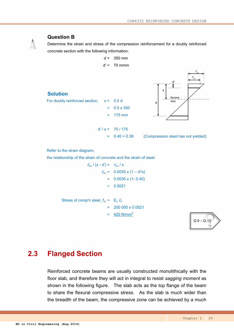
Question B Determine the strain and stress of the compression reinforcement for a doubly reinforced
concrete section with the following information:
d = 350 mm
d' = 70 mmm
Solution For doubly reinforced section, x = 0.5 d
= 0.5 x 350
= 175 mm
d' / x = 70 / 175
= 0.40 > 0.38 (Compression steel has not yielded)
Refer to the strain diagram,
the relationship of the strain of concrete and the strain of steel:
Ɛsc / (x - d') = Ɛcu / x
Ɛsc = 0.0035 x (1 – d'/x)
= 0.0035 x (1- 0.40)
= 0.0021
Stress of comp'n steel, fsc = Es Ɛs
= 200 000 x 0.0021
= 420 N/mm2
2.3 Flanged Section
Reinforced concrete beams are usually constructed monolithically with the
floor slab, and therefore they will act in integral to resist sagging moment as
shown in the following figure. The slab acts as the top flange of the beam
to share the flexural compressive stress. As the slab is much wider than
the breadth of the beam, the compressive zone can be achieved by a much
?Q.9 – Q.13

CON4332 REINFORCED CONCRETE DESIGN
Chapter 2 25
HD in Civil Engineering (Aug 2014)
shallower neutral axis, which, in most circumstances, falls within the flange
without trespassing into the web of the beam. On the other hand, the
flange does not assist in resisting the hogging moment at the supports,
where the compression zone is at the bottom of the section.
Figure 2.9 – Slab Acting as the Flange of a Beam (Isometric View) (For clarity of illustration, the main beams supporting beam A-B are not shown)

CON4332 REINFORCED CONCRETE DESIGN
Chapter 2 26
HD in Civil Engineering (Aug 2014)
beff
bw
T – Section
hd
bw
beff
L – Section
hf
Compression
Tension
Figure 2.10 – Flanged Sections
2.3.1 Effective Flange Width
The flexural compressive stress in the flange is assumed to be uniformly
distributed over an effective width, beff, which depends on the dimensions of
the beam & slabs and the length of the sagging moment, lpi, which may be
obtained from the following figures.
Figure 2.11 – Definition of lpi
for Calculation of Effective Flange Width
(Figure 5.1 of HKCP-2013)
For simply-supported beam, the whole span is under sagging moment, and
therefore, lpi = effective span of the simply-supported beam (L).
Notes:
(a) The length of the cantilever, l3, should be less than half the adjacent span.
(b) The ratio of the adjacent spans should lie between 2/3 and 1.5.

CON4332 REINFORCED CONCRETE DESIGN
Chapter 2 27
HD in Civil Engineering (Aug 2014)
Figure 2.12 – Effective Flange Width
(Figure 5.2 of HKCP-2013)
The design of flanged section for bending can be simply treated as the
design of rectangular section by putting:
b = beff
provided that the neutral axis is within the flange, i.e.
x ≤ hf
or (d – z) / 0.45≤ hf [2.11]
where hf is the thickness of the flange, i.e. the slab.
2.3.2 Examples – Flanged Section
Question A Determine the effective flange width for an interior span of a continuous beam with
approximately equal spans with the following information:
Breadth, bw = 350 mm
c/c distance of adjacent slabs

CON4332 REINFORCED CONCRETE DESIGN
Chapter 2 28
HD in Civil Engineering (Aug 2014)
Effective span, L = 6 700 mm
Clear spacing btw adjacent beams = 2 500mm (same on both sides)
Solution Internal span of ctu beam lpi = 0.7 x 6700
= 4 690 mm
b1 = b2 = 2 500 / 2
= 1250 mm
beff,1 = beff,2 = Min (0.2x1250+0.1x4690 or 0.2x4690 or 1250)
= Min (719 or 938 or 1250)
= 719 mm
beff = 2 x 719 + 350
= 1788 mm
Note: As 719 > 0.1 x 4690, the shear stress between the web and flange has to be checked,
i.e. Note 1 of Figure 2.12, which is outside the scope of this chapter and is ignored for the
purpose of this course.
Question B Determine the effective flange width for the following simply-supported beam:
Breadth, bw = 300 mm
Effective span, L = 9 000 mm
Clear spacing btw adjacent beams = 2 000mm (same on both sides)
Solution Simply supported beam lpi = 9000
b1 = b2 = 2000 / 2
= 1000 mm
beff,1 = beff,2 = Min (0.2x1000+0.1x9000 or 0.2x9000 or 1000)
= Min (1100 or 1800 or 1000)
= 1000 mm
beff = 2 x 1000 + 300
= 2300 mm
CON4332 REINFORCED CONCRETE DESIGN
Chapter 2 29
HD in Civil Engineering (Aug 2014)
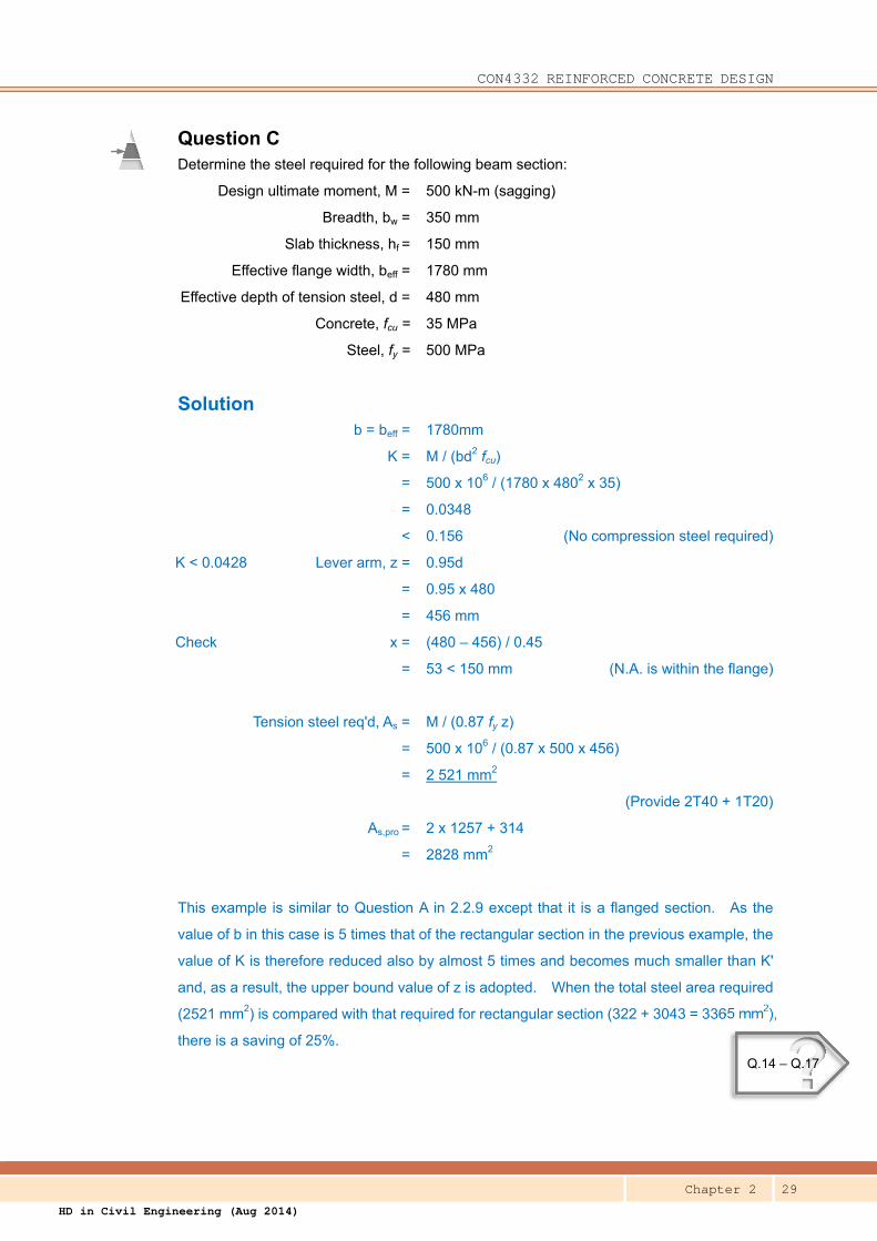
Question C Determine the steel required for the following beam section:
Design ultimate moment, M = 500 kN-m (sagging)
Breadth, bw = 350 mm
Slab thickness, hf = 150 mm
Effective flange width, beff = 1780 mm
Effective depth of tension steel, d = 480 mm
Concrete, fcu = 35 MPa
Steel, fy = 500 MPa
Solution b = beff = 1780mm
K = M / (bd2 fcu)
= 500 x 106 / (1780 x 4802 x 35)
= 0.0348
< 0.156 (No compression steel required)
K < 0.0428 Lever arm, z = 0.95d
= 0.95 x 480
= 456 mm
Check x = (480 – 456) / 0.45
= 53 < 150 mm (N.A. is within the flange)
Tension steel req'd, As = M / (0.87 fy z)
= 500 x 106 / (0.87 x 500 x 456)
= 2 521 mm2
(Provide 2T40 + 1T20)
As,pro = 2 x 1257 + 314
= 2828 mm2
This example is similar to Question A in 2.2.9 except that it is a flanged section. As the
value of b in this case is 5 times that of the rectangular section in the previous example, the
value of K is therefore reduced also by almost 5 times and becomes much smaller than K'
and, as a result, the upper bound value of z is adopted. When the total steel area required
(2521 mm2) is compared with that required for rectangular section (322 + 3043 = 3365 mm2),
there is a saving of 25%.
?Q.14 – Q.17

CON4332 REINFORCED CONCRETE DESIGN
Chapter 2 30
HD in Civil Engineering (Aug 2014)
2.4 Limits to Bar Spacing and Steel Ratio
There are lower and upper limits to the amount of steel and the spacing
between bars in reinforced concrete. The lower bound is to prevent
unsightly cracking due to shrinkage, temperature effect, restrained action
and brittle failure. On the other hand, the upper bound is to prevent
congestion of reinforcement bars that would affect the proper compaction of
concrete.
2.4.1 Bar Spacing
Adequate clear spacing should be provided
between bars such that concrete can be placed
and compacted satisfactorily around the bars.
The clear distance (horizontal and vertical)
between individual or horizontal layers of parallel
bars should not be less than (Cl.8.2 of
HKCP-2013):
i. maximum bar size
ii. aggregate size + 5 mm
iii. 20 mm
On the other hands, reinforcement bars cannot be placed too far apart; they
have to be placed close enough to distribute the cracks on the surface of the
concrete element. The maximum spacing of the bars is determined by the
service stress in the rebars, their distance from the concrete surface and the
thickness of the concrete element. Detailed requirements for beams and
slabs can be found in Cl.9.2.1.4 and Cl.9.3.1.1 of HKCP-2013. They will not
be covered in this chapter. For simplicity, the following rules of thumb can
be adopted for preliminary design:
For beam, the maximum bar spacing requirement can in general be
complied with by providing one bar for every 100 to 150 mm width of the
beam.
CON4332 REINFORCED CONCRETE DESIGN
Chapter 2 31
HD in Civil Engineering (Aug 2014)
Example
For a beam of 400 mm wide, provide 3 to 4 bars at the outer layer depending on the size
of the bars.
For slab, under most circumstances, limit the spacing of main bars to not
more than 2h or 250 mm whichever is lesser.
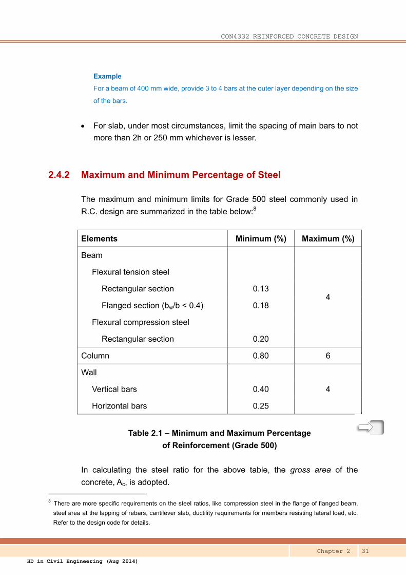
2.4.2 Maximum and Minimum Percentage of Steel
The maximum and minimum limits for Grade 500 steel commonly used in
R.C. design are summarized in the table below:8
Elements Minimum (%) Maximum (%)
Beam
4
Flexural tension steel
Rectangular section 0.13
Flanged section (bw/b < 0.4) 0.18
Flexural compression steel
Rectangular section 0.20
Column 0.80 6
Wall
4 Vertical bars 0.40
Horizontal bars 0.25
Table 2.1 – Minimum and Maximum Percentage
of Reinforcement (Grade 500)
In calculating the steel ratio for the above table, the gross area of the
concrete, Ac, is adopted. 8 There are more specific requirements on the steel ratios, like compression steel in the flange of flanged beam,
steel area at the lapping of rebars, cantilever slab, ductility requirements for members resisting lateral load, etc.
Refer to the design code for details.

CON4332 REINFORCED CONCRETE DESIGN
Chapter 2 32
HD in Civil Engineering (Aug 2014)
Overall depth, h,
instead of effective
depth, d, is used to
check steel ratio.
For rectangular section, Ac = bh
For flanged section, Ac = bwh
Example
For a beam of 600 (h) x 300 (b), the minimum flexural tension
steel is 0.13 x 600 x 300 / 100 = 234 mm2.
?Q.18 – Q.19
CON4332 REINFORCED CONCRETE DESIGN
Chapter 2 33
HD in Civil Engineering (Aug 2014)
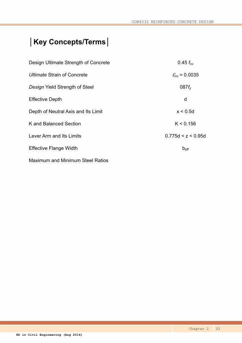
│Key Concepts/Terms│
Design Ultimate Strength of Concrete 0.45 fcu
Ultimate Strain of Concrete Ɛcu = 0.0035
Design Yield Strength of Steel 087fy
Effective Depth d
Depth of Neutral Axis and Its Limit x < 0.5d
K and Balanced Section K < 0.156
Lever Arm and Its Limits 0.775d < z < 0.95d
Effective Flange Width beff
Maximum and Minimum Steel Ratios

CON4332 REINFORCED CONCRETE DESIGN
Chapter 2 34
HD in Civil Engineering (Aug 2014)
│Self-Assessment Questions│
Q.1 Find the effective depth, d, of the following beam section.
Overall beam depth, h = 600 mm Referred size of link: 10
Concrete cover = 40 mm Preferred size of main bars: 40
A. 510 mm
B. 530 mm
C. 265 mm
D. 550 mm
Q.2 Find the effective depth, d, of the following beam section.
Overall beam depth, h = 625 mm Referred size of link: 12
Concrete cover = 40 mm Main bars: 2 layers of 32
A. 557 mm
B. 541 mm
C. 525 mm
D. 312.5 mm
Q.3 Find the effective depth, d, of the following slab section.
Overall slab thickness, h = 175 mm
Concrete cover = 25 mm Preferred size of main bars: 12
A. 159 mm
B. 138 mm
C. 144 mm
D. 150 mm

CON4332 REINFORCED CONCRETE DESIGN
Chapter 2 35
HD in Civil Engineering (Aug 2014)
Q.4 Determine the allowable depth of the neutral axis, x, of the following rectangular beam
section.
Overall beam depth, h = 600 mm Referred size of link: 10
Concrete cover = 35 mm Preferred size of main bars: 32
βb = 1.0
A. 322 mm
B. 300 mm
C. 539 mm
D. 269.5 mm
Q.5 Determine the K value for the following rectangular beam section.
Design ultimate moment, M = 350 kN-m βb = 1.0
Breadth, b = 300 mm
Effective depth, d = 454 mm Overall depth, h = 520mm
Concrete, fcu = 40 MPa
A. 0.142
B. 0.108
C. 1.415
D. 0.124

CON4332 REINFORCED CONCRETE DESIGN
Chapter 2 36
HD in Civil Engineering (Aug 2014)
Q.6 Determine the amount of tension steel, As, required for the following rectangular beam
section.
Design ultimate moment, M = 422 kN-m βb = 1.0
Breadth, b = 325 mm Effective depth, d = 534 mm
Concrete, fcu = 40 MPa Steel, fy = 500 MPa
A. 3212 mm2
B. 2320 mm2
C. 1856 mm2
D. 2134 mm2
Q.7 Determine the amount of tension steel, As, required for the following rectangular beam
section.
Design ultimate moment, M = 153 kN-m βb = 1.0
Breadth, b = 350 mm Effective depth, d = 534 mm
Concrete, fcu = 30 MPa Steel, fy = 500 MPa
A. 701 mm2
B. 2320 mm2
C. 1856 mm2
D. 693 mm2
Q.8 Determine the amount of tension steel, As, required for the following rectangular beam
section.
Design ultimate moment, M = 26 kN-m βb = 0.8
Breadth, b = 1000 mm Effective depth, d = 169 mm
Concrete, fcu = 30 MPa Steel, fy = 500 MPa
A. 372 mm2
B. 366 mm2
C. 327 mm2
D. 701 mm2

CON4332 REINFORCED CONCRETE DESIGN
Chapter 2 37
HD in Civil Engineering (Aug 2014)
Q.9 Determine the lever arm, z, for the following rectangular beam section.
K = 0.178 βb = 1.0
Breadth, b = 350 mm Effective depth, d = 634 mm
Concrete, fcu = 30 MPa Steel, fy = 500 MPa
A. 462 mm
B. 426 mm
C. 317 mm
D. 491 mm
Q.10 Determine the compression steel, A's, required for the following rectangular beam section.
K = 0.188 βb = 1.0
Breadth, b = 350 mm Overall depth, h = 700 mm
Effective depth, d = 634 mm d' = 70 mm
Concrete, fcu = 35 MPa Steel, fy = 500 MPa
A. 3617 mm2
B. 642 mm2
C. 4776 mm2
D. 491 mm2

CON4332 REINFORCED CONCRETE DESIGN
Chapter 2 38
HD in Civil Engineering (Aug 2014)
Q.11 Determine the steel required for the following rectangular beam section.
Design ultimate moment, M = 683 kN-m βb = 1.0
Breadth, b = 350 mm Overall depth, h = 575 mm
Effective depth, d = 505 mm d' = 70 mm
Concrete, fcu = 40 MPa Steel, fy = 500 MPa
A. A's = 563 mm2 and As = 3525 mm2
B. A's = 563 mm2 and As = 4483 mm2
C. A's = 666 mm2 and As = 3272 mm2
D. A's = 666 mm2 and As = 3938 mm2
Q.12 Determine the steel required for the following rectangular beam section.
Design ultimate moment, M = 766 kN-m βb = 1.0
Breadth, b = 400 mm Overall depth, h = 545 mm
Effective depth, d = 475 mm d' = 70 mm
Concrete, fcu = 40 MPa Steel, fy = 500 MPa
A. A's = 1151 mm2 and As = 4668 mm2
B. A's = 1151 mm2 and As = 3516 mm2
C. A's = 666 mm2 and As = 3272 mm2
D. A's = 666 mm2 and As = 3938 mm2
Q.13 Determine the lever arm, z, for the following rectangular beam section.
K = 0.150 βb = 0.8
Breadth, b = 350 mm Effective depth, d = 634 mm
Concrete, fcu = 30 MPa Steel, fy = 500 MPa
A. 462 mm
B. 520 mm
C. 317 mm
D. 491 mm

CON4332 REINFORCED CONCRETE DESIGN
Chapter 2 39
HD in Civil Engineering (Aug 2014)
Q.14 Determine the effective flange width, beff, for the end span of a continuous beam with
approximately equal spans with the following information:
Breadth, bw = 300 mm
Effective span, L = 7 700 mm
Clear distance between adjacent beams = 2 600mm (same on both sides)
A. 2918 mm
B. 2600 mm
C. 2129 mm
D. 1829 mm
Q.15 Determine the effective flange width, beff, for the following simply-supported beam:
Breadth, bw = 250 mm (same for adjacent beams)
Effective span, L = 8 700 mm
c/c distance between adjacent beams = 3000mm (same on both sides)
A. 1395 mm
B. 2290 mm
C. 2540 mm
D. 2750 mm

CON4332 REINFORCED CONCRETE DESIGN
Chapter 2 40
HD in Civil Engineering (Aug 2014)
Q.16 Determine the lever arm, z, for the following flanged beam section.
Design ultimate moment, M = 666 kN-m (sagging) βb = 1.0
Breadth, bw = 400 mm Effective flange width, beff = 2150 mm
Effective depth, d = 485 mm hf = 200 mm
Concrete, fcu = 40 MPa Steel, fy = 500 MPa
A. 457 mm
B. 355 mm
C. 376 mm
D. 461 mm
Q.17 Determine the steel area required for the following flanged beam section.
Design ultimate moment, M = 668 kN-m (sagging) βb = 1.0
Breadth, bw = 350 mm Effective flange width, beff = 2050 mm
Effective depth, d = 486 mm hf = 190 mm
Concrete, fcu = 40 MPa Steel, fy = 500 MPa
A. A's = 0 mm2 and As = 3326 mm2
B. A's = 0 mm2 and As = 4077 mm2
C. A's = 823 mm2 and As = 4900 mm2
D. A's = 823 mm2 and As = 3326 mm2
Q.18 In the design of a 600mm (h) x 400mm (b) reinforced concrete beam, if the amount of steel
required for resisting the design moment by the rectangular section is found to be 210 mm2,
which of the following reinforcement is most appropriate?
A. 2T12
B. 2T16
C. 4T12
D. 1T20

CON4332 REINFORCED CONCRETE DESIGN
Chapter 2 41
HD in Civil Engineering (Aug 2014)
Q.19 In the design of a 400mm x 400mm reinforced concrete column, if the amount of steel
required for resisting the design axial force is found to be 1250 mm2, which of the following
reinforcement is most appropriate?
A. 4T20
B. 3T25
C. 4T25
D. 12T32
Q.20 Which of the following is the most appropriate rebars for the flanged beam under sagging
moment as described below?
Breadth, bw = 600 mm Effective flange width, beff = 2050 mm
Effective depth, d = 350 mm hf = 150 mm
Overall depth, h = 400 mm
The amount of bottom steel required to resist the sagging moment = 380 mm2
A. 2T20
B. 2T16
C. 4T12
D. 5T12

CON4332 REINFORCED CONCRETE DESIGN
Chapter 2 42
HD in Civil Engineering (Aug 2014)
Answers:
Q1 B d = 600 – 40 – 10 – 40/2 = 530 mm
Q2 C d = 625 – 40 – 12 – 32 – 32/2 = 525 mm
Q3 C d = 175 – 25 – 12/2 = 144 mm
Q4 D max x = 0.5d = 0.5 x (600 – 35 -10 – 32/2) = 269.5 mm
Q5 A K = 350 x 106 / (300 x 4542 x 40) = 0.142
Q6 D K = 0.114; z = 0.851 x 534 = 454.7mm; As = 422 x 106 / (0.87 x 500 x 454.7) = 2134 mm2
Q7 A K = 0.0511; z = 0.940 x 534 = 501.7mm; As = 153 x 106 / (0.87 x 500 x 501.7) = 701 mm2
Q8 A K = 0.0303; z = 0.95 x 169 = 160.6mm, As = 26 x 106 / (0.87 x 500 x 160.6) = 372 mm2
Q9 D K = 0.178 > 0.156, therefore, z = 0.775 x 634 = 492 mm
Q10 B As' = (0.188-0.156)x35x350x6342 / (0.87x500x(634-70)) = 643 mm2
Q11 D K = 0.1913; As' = (0.1913-0.156)x40x350x5052 / (0.87x500x(505-70)) = 666 mm2; As =
0.156x40x350x5052 / (0.87x500x0.775x505) + 666 = 3938 mm2
Q12 A K = 0.2122; As' = (0.2122-0.156)x40x400x4752 / (0.87x500x(475-70)) = 1151 mm2; As =
0.156x40x400x4752 / (0.87x500x0.775x475) + 1151 = 4668 mm2
Q13 B βb = 0.8 < 0.9, max x = (βb – 0.4)d = 0.4 x 634 = 253.6; z = 634 – 0.45 x 253.6 = 520mm
Q14 C bi = 2600/2 = 1300mm; lpi = 0.85x7700 = 6545mm; beff = 2 x min(0.2x1300+0.1x6545, 0.2x6545,
1150) + 300 = 2129 mm
Q15 C bi = (3000-250)/2 = 1375mm; lpi = 8700mm; beff = 2 x min(0.2x1375+0.1x8700, 0.2x8700, 1150) +
250 = 2540 mm
Q16 D K = 0.0329 < 0.0428; z = 0.95 x 485 = 461 mm
Q17 A K = 0.0345 < 0.0428; z = 0.95 x 486 = 461.7 mm; As = 668 x 106 / (0.87 x 500 x 461.7) = 3326 mm2
Q18 C Min As = 0.13x600x400/100 = 312 > 210 mm2; preferably provide 4 bars over 400mm; therefore
use 4T12, As = 452 mm2
Q19 C (A) 100As/bh = 0.785 < 0.8 unacceptable; (B) At least 4 bars; (D) 100As/bh = 6.03 > 3 unacceptable
Q20 D Min As = 0.18x600x400/100 = 432 > 380; although the steel area 4T12 is ok, it is preferable to
provide at least 5 – 6 bars over the width of 600mm.
CON4332 REINFORCED CONCRETE DESIGN
Chapter 2 43
HD in Civil Engineering (Aug 2014)
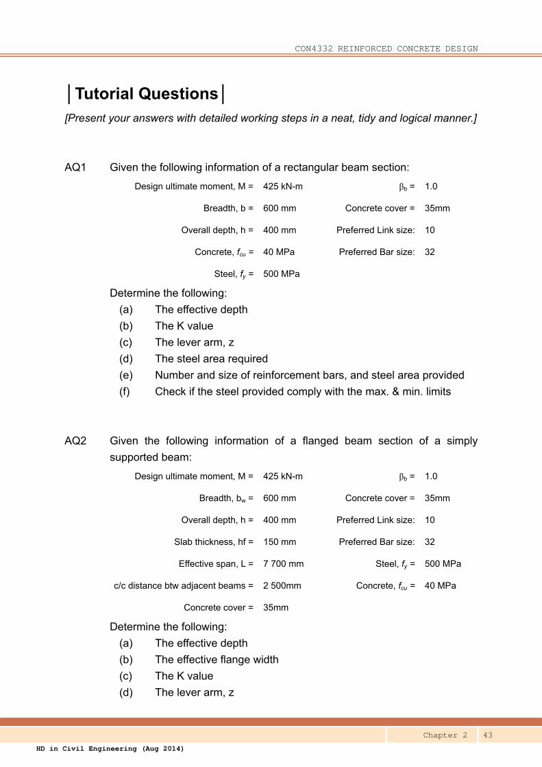
│Tutorial Questions│
[Present your answers with detailed working steps in a neat, tidy and logical manner.]
AQ1 Given the following information of a rectangular beam section:
Design ultimate moment, M = 425 kN-m βb = 1.0
Breadth, b = 600 mm Concrete cover = 35mm
Overall depth, h = 400 mm Preferred Link size: 10
Concrete, fcu = 40 MPa Preferred Bar size: 32
Steel, fy = 500 MPa
Determine the following:
(a) The effective depth
(b) The K value
(c) The lever arm, z
(d) The steel area required
(e) Number and size of reinforcement bars, and steel area provided
(f) Check if the steel provided comply with the max. & min. limits
AQ2 Given the following information of a flanged beam section of a simply
supported beam:
Design ultimate moment, M = 425 kN-m βb = 1.0
Breadth, bw = 600 mm Concrete cover = 35mm
Overall depth, h = 400 mm Preferred Link size: 10
Slab thickness, hf = 150 mm Preferred Bar size: 32
Effective span, L = 7 700 mm Steel, fy = 500 MPa
c/c distance btw adjacent beams = 2 500mm Concrete, fcu = 40 MPa
Concrete cover = 35mm
Determine the following:
(a) The effective depth
(b) The effective flange width
(c) The K value
(d) The lever arm, z

CON4332 REINFORCED CONCRETE DESIGN
Chapter 2 44
HD in Civil Engineering (Aug 2014)
(e) The steel area required
(f) Number and size of reinforcement bars, and steel area provided
(g) Check if the steel provided comply with the max. & min. limits
AQ3 Identify the assumptions that have been made in deriving the formulae for
bending.