ANNEX 14 RESOLUTION MEPC.108(49) Adopted on …...MEPC 49/22/Add.2 ANNEX 14 RESOLUTION MEPC.108(49)...
48
MEPC 49/22/Add.2 ANNEX 14 RESOLUTION MEPC.108(49) Adopted on 18 July 2003 REVISED GUIDELINES AND SPECIFICATIONS FOR OIL DISCHARGE MONITORING AND CONTROL SYSTEMS FOR OIL TANKERS THE MARINE ENVIRONMENT PROTECTION COMMITTEE, RECALLING Article 38(a) of the Convention on the International Maritime Organization concerning the functions of the Marine Environment Protection Committee conferred upon it by international conventions for the prevention and control of marine pollution, NOTING that regulation 15(3)(a) of Annex I of the International Convention for the Prevention of Pollution from Ships, 1973, as modified by the Protocol of 1978 relating thereto (MARPOL 73/78), specifies that oil tankers of 150 gross tonnage and above shall be fitted with an oil discharge and monitoring control system approved by the Administration and designed and installed in compliance with the Guidelines and Specifications for Oil Discharge Monitoring and Control Systems for Oil Tankers adopted by the Organization, NOTING ALSO resolution A.586(14) entitled “Revised Guidelines and Specifications for Oil Discharge Monitoring and Control Systems for Oil Tankers” developed in implementation of the said regulation, NOTING FURTHER regulation 14 of Annex II of MARPOL 73/78 in respect of the carriage of category C and D oil-like substances in oil tankers, RECALLING that by resolution A.886(21) the Assembly resolved that, in order to establish a uniform procedure, the function of adopting or amending performance standards and technical specifications referred to in the substantive text of MARPOL 73/78 and other IMO instruments, shall be performed by the Marine Environment Protection Committee and/or the Maritime Safety Committee, as appropriate, HAVING CONSIDERED, at its forty-ninth session, the recommendation submitted by the Sub-Committee on Ship Design and Equipment in light of the requirements of Annex I of MARPOL 73/78, 1. ADOPTS the Revised Guidelines and Specifications for Oil Discharge Monitoring and Control Systems for Oil Tankers, the text of which is set out in the Annex to this resolution, for application to oil tankers the keels of which are laid or which are in a similar stage of construction (hereinafter referred to as “constructed”) on or after 1 January 2005; 2. INVITES Governments to implement these Revised Guidelines and Specifications when approving oil discharge monitoring and control systems being installed under regulation 15(3)(a) of Annex I of MARPOL 73/78 on oil tankers constructed on or after 1 January 2005.
Transcript of ANNEX 14 RESOLUTION MEPC.108(49) Adopted on …...MEPC 49/22/Add.2 ANNEX 14 RESOLUTION MEPC.108(49)...

MEPC 49/22/Add.2
ANNEX 14
RESOLUTION MEPC.108(49)
Adopted on 18 July 2003
REVISED GUIDELINES AND SPECIFICATIONS FOR OIL DISCHARGE MONITORING AND CONTROL SYSTEMS FOR OIL TANKERS
THE MARINE ENVIRONMENT PROTECTION COMMITTEE,
RECALLING Article 38(a) of the Convention on the International Maritime Organization concerning the functions of the Marine Environment Protection Committee conferred upon it by international conventions for the prevention and control of marine pollution, NOTING that regulation 15(3)(a) of Annex I of the International Convention for the Prevention of Pollution from Ships, 1973, as modified by the Protocol of 1978 relating thereto (MARPOL 73/78), specifies that oil tankers of 150 gross tonnage and above shall be fitted with an oil discharge and monitoring control system approved by the Administration and designed and installed in compliance with the Guidelines and Specifications for Oil Discharge Monitoring and Control Systems for Oil Tankers adopted by the Organization, NOTING ALSO resolution A.586(14) entitled “Revised Guidelines and Specifications for Oil Discharge Monitoring and Control Systems for Oil Tankers” developed in implementation of the said regulation, NOTING FURTHER regulation 14 of Annex II of MARPOL 73/78 in respect of the carriage of category C and D oil- like substances in oil tankers, RECALLING that by resolution A.886(21) the Assembly resolved that, in order to establish a uniform procedure, the function of adopting or amending performance standards and technical specifications referred to in the substantive text of MARPOL 73/78 and other IMO instruments, shall be performed by the Marine Environment Protection Committee and/or the Maritime Safety Committee, as appropriate, HAVING CONSIDERED, at its forty-ninth session, the recommendation submitted by the Sub-Committee on Ship Design and Equipment in light of the requirements of Annex I of MARPOL 73/78, 1. ADOPTS the Revised Guidelines and Specifications for Oil Discharge Monitoring and Control Systems for Oil Tankers, the text of which is set out in the Annex to this resolution, for application to oil tankers the keels of which are laid or which are in a similar stage of construction (hereinafter referred to as “constructed”) on or after 1 January 2005; 2. INVITES Governments to implement these Revised Guidelines and Specifications when approving oil discharge monitoring and control systems being installed under regulation 15(3)(a) of Annex I of MARPOL 73/78 on oil tankers constructed on or after 1 January 2005.

MEPC 49/22/Add.2 ANNEX 14
Page 2
ANNEX
REVISED GUIDELINES AND SPECIFICATIONS FOR OIL DISCHARGE MONITORING AND CONTROL SYSTEMS FOR OIL TANKERS
TABLE OF CONTENTS 1 INTRODUCTION 1.1 Purpose 1.2 Applicability 1.3 Summary of requirements 2 BACKGROUND 3 DEFINITIONS 3.1 Oil discharge monitoring and control system 3.2 Control section 3.3 Overboard discharge control 3.4 Starting interlock 3.5 Control unit 3.6 PPM 4 IMPLEMENTATION REQUIREMENTS 5 CONSTRUCTION, MAINTENANCE, SECURITY, CALIBRATION AND TRAINING 6 TECHNICAL SPECIFICATIONS 6.1 Oil discharge monitoring and control system 6.2 Oil content meters 6.3 Sampling system 6.4 Flow rate indicating system 6.5 Ship’s speed indicating system 6.6 Ship position indicating device 6.7 Overboard discharge control management 6.8 Processor and transmitting device 6.9 Recording devices 6.10 Data display 6.11 Manually operated alternatives in the event of equipment malfunction 6.12 Alarm conditions resulting in the stopping of discharge 6.13 Location of alarm indicator

MEPC 49/22/Add.2 ANNEX 14
Page 3
7 SPECIFICATIONS FOR TYPE APPROVAL OF THE OIL CONTENT METER AND
THE CONTROL SECTION OF AN OIL DISCHARGE MONITORING AND CONTROL SYSTEM
7.1 Testing requirements 7.2 Approval and certification procedures 8 WORKSHOP FUNCTIONAL TEST REQUIREMENTS 9 PLAN APPROVAL REQUIREMENTS 10 GENERAL INSTALLATION REQUIREMENTS 11 INSTALLATION SURVEY 12 ON-BOARD FUNCTIONAL TEST AND CHECKOUT PROCEDURE ANNEX Part 1 - Test and performance specifications for type approval of oil content meters Part 2 - Specification for environmental testing for type approval of the oil content meter and
the control section of an oil discharge monitoring and control system Part 3 - Documentation of approval APPENDIX - Certificate of type approval for oil content meters intended for monitoring the
discharge of oil-contaminated water from the cargo tank areas of oil tankers

MEPC 49/22/Add.2 ANNEX 14
Page 4
1 INTRODUCTION 1.1 Purpose 1.1.1 These Guidelines and Specifications contain requirements regarding the design, installation, performance and testing of oil discharge monitoring and control systems on oil tankers as required by regulation 15(3)(a) of Annex I of MARPOL 73/78. 1.1.2 The purpose of these Guidelines and Specifications is:
.1 to provide a uniform interpretation of the requirements of regulation 15(3)(a) of Annex I of MARPOL 73/78;
.2 to assist Administrations in determining appropriate design, construction and
operational parameters for oil discharge monitoring and control systems for oil tankers, hereafter referred to as “monitoring systems”, when such systems are fitted in ships flying the flag of their State;
.3 to define test and performance requirements for oil content meters and control
sections forming part of monitoring systems; .4 to define requirements for plan approval of installations and functional testing of
installed equipment; and .5 to provide guidance for the survey of installations on board.
1.1.3 These Guidelines and Specifications also apply to oil content monitoring systems used for monitoring certain category C and D oil- like noxious liquid substances carried in accordance with regulation 14 of Annex II of MARPOL 73/78. Wherever in these Guidelines and Specifications reference is made to oil being monitored, this applies likewise to such oil- like noxious liquid substances. 1.2 Applicability 1.2.1 The Revised Guidelines and Specifications apply to equipment installed in oil tankers the keels of which are laid, or which are at a similar stage of construction, on or after 1 January 2005. The Guidelines and Specifications adopted under resolutions A.393(X), A.496(XII), MEPC.13(19) and A.586(14) are not applicable to oil tankers to which these new Guidelines and Specifications apply. 1.2.2 Equipment installed in other oil tankers the keels of which are laid, or are in a similar stage of construction, before 1 January 2005, should comply either with the requirements contained in the Guidelines and Specifications adopted under resolutions A.393(X), A.496(XII), MEPC.13(19) and A.586(14), as applicable, or with the requirements contained in these new Guidelines and Specifications. 1.3 Summary of requirements The approval requirements for various parts of a monitoring system as specified in these Guidelines and Specifications are summarized below:

MEPC 49/22/Add.2 ANNEX 14
Page 5
.1 the oil content meter should be tested for type approval in accordance with the procedures described in part 1 of the Annex;
.2 the oil content meter and the control section of a monitoring system should be
subjected to the environmental tests specified in part 2 of the annex; .3 documentation for plan approval, as specified in section 8, should be submitted to
the Administration prior to the installation of the monitoring system; .4 the component parts of the system should undergo the workshop functional tests
specified in section 8; and .5 the complete monitoring system should be surveyed in accordance with the
procedures laid down in section 11. 2 BACKGROUND 2.1 The requirements of Annex I of MARPOL 73/78 relating to oil content monitoring of oil tanker ballast and tank washing water are set out in regulation 15(3)(a), which stipulates that oil tankers of 150 tons gross tonnage and above should be equipped with an approved monitoring system and that such system should record continuously:
.1 the discharge of oil in litres per nautical mile; and
.2 the total quantity of oil discharged, or alternatively, the oil content of the effluent and the rate of discharge.
In both cases, the record should be identifiable as to time and date and should be kept for at least three years. 2.2 Regulation 15 also stipulates that the system should come into operation when there is any discharge of effluent into the sea and should be such as will ensure that any discharge of oily mixture is automatically stopped when the instantaneous rate of discharge of oil exceeds that permitted by regulation 9(1)(a). 3 DEFINITIONS 3.1 Oil discharge monitoring and control system An oil discharge monitoring and control system, referred to in these Guidelines and Specifications as a “monitoring system”, is a system which monitors the discharge into the sea of oily ballast or other oil-contaminated water from the cargo tank areas and comprises the items specified in paragraph 6.1.4. 3.2 Control section A control section of a monitoring system is a unit composed of the items specified in paragraph 6.1.4.8.

MEPC 49/22/Add.2 ANNEX 14
Page 6
3.3 Overboard discharge control An overboard discharge control is a device which automatically initiates the sequence to stop the overboard discharge of the effluent in alarm conditions and prevents the discharge throughout the period the alarm condition prevails. The device may be arranged to close the overboard valves or to stop the relevant pumps, as appropriate. 3.4 Starting interlock A starting interlock is a facility which prevents the initiation of the opening of the discharge valve or the operation of other equivalent arrangements before the monitoring system is fully operational when use of the monitoring system is required by the Convention. 3.5 Control unit 3.5.1 A control unit is a device which receives automatic signals of:
.1 oil content of the effluent ppm;
.2 flow rate of discharge m3/hour;
.3 ship’s speed in knots;
.4 ship's position - latitude and longitude;
.5 date and time (GMT); and .6 status of the overboard discharge control.
3.5.2 The unit shall make automatic recordings of data as specified in paragraph 6.9.2. 3.6 ppm “ppm” means parts of oil per million parts of water by volume. 4 IMPLEMENTATION REQUIREMENTS Oil Discharge Monitoring and Control Systems should be fitted to oil tankers of 150 gross tonnage and above. It should employ a control unit and be fitted with a starting interlock and overboard discharge control.
MEPC 49/22/Add.2 ANNEX 14
Page 7
5 CONSTRUCTION, MAINTENANCE, SECURITY, CALIBRATION AND TRAINING 5.1 The instrument should be designed to ensure that user access is restricted to essential controls. Access beyond these controls should be available for emergency maintenance and temporary repair but must require the breaking of security seals or activation of another device which indicates an entry to the equipment. 5.2 The seals should be of a design that only the manufacturer or his agent can replace the seals or reset the system following inspection and permanent repairs to the equipment. 5.3 The accuracy of the Oil Discharge Monitoring equipment should be verified at the IOPP renewal surveys. The calibration certificate certifying date of last calibration check should be retained on board for inspection purposes. 5.4 The ODME unit may have several scales as appropriate for its intended use. The recording device fitted to a meter which has more than one scale should indicate the scale which is in use. 5.5 It is recommended that simple means be provided aboard ship to check on instrument drift, repeatability of the instrument reading, and the ability to re-zero the instrument. 5.6 Ship staff training should include familiarisation in the operation and the maintenance of the equipment. 5.7 The routine maintenance of the Oil Discharge Monitoring Equipment and troubleshooting procedures should be clearly defined by the manufacturer in the Operating and Maintenance Manual. All routine maintenance and repairs to be recorded. 6 TECHNICAL SPECIFICATIONS 6.1 Oil discharge monitoring and control system 6.1.1 The monitoring system should be capable of effectively monitoring and controlling the discharge of any effluent into the sea through those overboard discharge outlets permitted by regulation 18 which, in the opinion of the Administration, are necessary to fulfil the operational requirements of the oil tanker. 6.1.2 The discharge of dirty ballast water or other oil-contaminated water from the cargo tank areas into the sea through outlets which are not controlled by the monitoring system is an infringement of the Convention. 6.1.3 The monitoring system should function effectively under all environmental conditions which oil tankers are normally assumed to encounter, and should be designed and constructed to satisfy the specifications for environmental testing specified in part 2 of the annex to these Guidelines and Specifications. Moreover,
.1 the system should be so designed that no discharge of dirty ballast or other oil-contaminated water from the cargo tank areas can take place unless the monitoring system is in the normal operating mode and the relevant sampling point has been selected;

MEPC 49/22/Add.2 ANNEX 14
Page 8
.2 preferably the system should sample the effluent discharge from a minimum number of discharge outlets and be so arranged that discharge overboard can take place via only one outlet at a time;
.3 where it is intended that more than one line be used for simultaneous discharging
purposes, one oil content meter, together with a flow meter, should be installed in each discharge line. These instruments should be connected to a common processor; and
.4 in order to avoid alarms due to short-term high oil concentration signals (spikes) causing indications of high instantaneous rates of discharge, the short-term high ppm signal may be suppressed for a maximum of 10 s. Alternatively, the instantaneous rate of discharge may be continuously averaged during the preceding 20 s or less as computed from instantaneous ppm values of the oil content meter readings received at intervals not exceeding 5 s.
6.1.4 The monitoring system should comprise:
.1 an oil content meter to measure the oil content of the effluent in ppm. The meter should be approved in accordance with the provisions contained in the annex to these Guidelines and Specifications and be certified to take into account the range of cargoes carried;
.2 a flow rate indicating system to measure the rate of effluent being discharged into
the sea; .3 a ship speed indicating device to give the ship’s speed in knots; .4 a ship position indicating device to give the ship's position – latitude and
longitude; .5 a sampling system to convey a representative sample of the effluent to the oil
content meter; .6 an overboard discharge control to stop the overboard discharge; .7 a starting interlock to prevent the discharge overboard of any effluent unless the
monitoring system is fully operational; and .8 a control section comprising:
.8.1 a processor, which accepts signals of oil content in the effluent, the
effluent flow rate and the ship’s speed and computes these values into litres of oil discharged per nautical mile and the total quantity of oil discharged;
.8.2 means to provide alarms and command signals to the overboard discharge
control; .8.3 a recording device to provide a record of data in accordance with
paragraph 6.9.2;
MEPC 49/22/Add.2 ANNEX 14
Page 9
.8.4 a data display to exhibit the current operational data in accordance with paragraph 6.10;
.8.5 a manual override system to be used in the event of failure of the
monitoring system; and .8.6 means to provide signals to the starting interlock to prevent the discharge
of any effluent before the monitoring system is fully operational.
6.1.5 Each main component of the oil content monitoring system should be fitted with a name-plate, properly identifying the component by assembly drawing number, type or model number and serial number, as appropriate. 6.1.6 If installed in a hazardous area, the electrical components of the monitoring system should meet the appropriate safety requirements∗ laid down for these areas. 6.2 Oil content meter 6.2.1 An oil content meter should satisfy the test and performance specifications contained in part 1 of the Annex to these Guidelines and Specifications and should conform with the general requirements contained in this subsection. 6.2.2 The accuracy of meters designed to monitor a wide range of oil content should be such that the reading will represent the actual oil content of the sample being tested within +10 ppm or +10%, whichever is the greater. The accuracy should remain within the above limit despite the presence of contaminants other than oil, such as entrained air, rust, mud and sand. 6.2.3 The meter should be designed so that it functions within the above limit when the power supply (in the form of electricity, compressed air, etc.) is varied by 10% from the value for which the meter is designed. 6.2.4 It is desirable that the reading should not be affected by the type of oil. If it is, it should not be necessary to calibrate the meter on board ship, but pre-set alterations in the calibration may be made in accordance with the manufacturer’s instructions. In the latter case, means should be available to check that the correct calibration has been selected for the oil in question. The accuracy of the readings should at all times remain within the limit specified in 6.2.2. 6.2.5 The response time of the meter, as defined in paragraph 1.2.8 of part 1 of the annex, should not exceed 20 s. 6.2.6 The meter may have several scales as appropriate for its intended use. The full range of the scale should not be less than 1,000 ppm. 6.2.7 The meter should have simple means to enable the ship’s crew to check the functioning of the electrical and electronic circuitry of the meter by introduction of a simulated signal corresponding approximately to half the full-scale reading of the meter. It should also be possible for qualified personnel to recalibrate the meter on board the oil tanker.
∗ As specified in IEC publication 92 or its equivalent.

MEPC 49/22/Add.2 ANNEX 14
Page 10
6.2.8 The meter should, if intended to be fitted in locations where flammable atmospheres may be present, comply with the relevant safety regulations for such spaces. Any electrical equipment which is part of the meter should be placed in a non-hazardous area, or should be certified by the Administration as safe for use in a hazardous atmosphere. Any moving parts which are fitted in hazardous areas should be so arranged as to avoid the formation of static electricity. 6.2.9 The meter should not contain or use any substance of a dangerous nature, unless adequate arrangements, acceptable to the Administration, are provided to eliminate any hazard introduced thereby. 6.2.10 The meter should resist corrosion in conditions of the marine environment. 6.2.11 The meter should be constructed from materials compatible with the liquids to be tested. 6.3 Sampling system 6.3.1 Sampling points should be so located that relevant samples can be obtained from those outlets that are used for operational discharges in accordance with paragraph 6.1.1. The sampling probes located in the overboard discharge lines and the piping system connecting the sampling probes to the oil content meter should meet the requirements of this section. 6.3.2 The piping and probes should be of a material resistant to fire, corrosion, and oil and be of adequate strength, properly jointed and supported. 6.3.3 The system should have a stop-valve fitted adjacent to each probe, except that, where the probe is mounted in a cargo line, two stop-valves shall be fitted, in series, in the sample line; one of these may be the remote controlled sample selector valve. 6.3.4 Sampling probes should be arranged for easy withdrawal and should as far as practicable be mounted at an accessible location in a vertical section of the discharge line. Should it be necessary to fit sampling probes in a horizontal section of the discharge line it should be ascertained, during the installation survey, that the pipe runs full of liquid at all times during the discharge of the effluent. Sampling probes should normally penetrate inside the discharge pipe to a distance of one quarter the diameter of that pipe. 6.3.5 Means should be provided for cleaning the probes and piping system by the provision of permanent clean water flushing arrangements or an equivalent method. The design of the probes and piping should be such as to minimize their clogging by oil, oily residue, and other matter. 6.3.6 The velocity of the fluid in the piping should be such that, taking into consideration the length of the piping, the overall response time should be as short as possible between an alteration in the mixture being pumped and the alteration in the meter reading and in any case not more than 40 s, including the response time of the meter. 6.3.7 The location of sampling probes in relation to any point of flow diversion to a slop tank should be selected with regard to the need for sampling the oily water in the recircula tion mode.

MEPC 49/22/Add.2 ANNEX 14
Page 11
6.3.8 The arrangements for driving the sampling pump or any other pumps used in the system should have regard to the safety requirements of the space in which the pump is located. Any bulkhead penetration between a hazardous and a non-hazardous area should be of a design approved by the Administration. 6.3.9 The flushing arrangement should be such that where necessary it can be utilized for test-running and stabilizing the oil content meter and correcting for zero setting. 6.3.10 Sample water returning to the slop tank should not be allowed to free-fall into the tank. In tankers equipped with an inert gas system a U-seal of adequate height should be arranged in the piping leading to a slop tank. 6.3.11 A valve should be provided for the manual collection of samples from the inlet piping to the meter at a point downstream of any sampling pump or at an equivalent location satisfactory to the Administration. 6.4 Flow rate indicating system 6.4.1 A flow meter for measuring the rate of discharge should be installed in a vertical section of a discharge line or in any other section of a discharge line as appropriate, so as to be always filled with the liquid being discharged. 6.4.2 A flow meter should employ an operating principle which is suitable for shipboard use and, where relevant, can be used in large diameter pipes. 6.4.3 A flow meter should be suitable for the full range of flow rates that may be encountered during normal operation. Alternatively, arrangements such as the use of two flow meters of different ranges or a restriction of the operational flow rate range may be necessary to meet this requirement. 6.4.4 The flow meter, as installed, should have an accuracy of +10%, or better, of the instantaneous rate of discharge throughout the operating range for discharging the effluent. 6.4.5 Any component part of the flow meter in contact with the effluent should be of corrosion-resistant and oil-resistant material of adequate strength. 6.4.6 The design of the flow metering arrangements should have regard to the safety requirements of the space in which such metering arrangements are located. 6.5 Ship’s speed indicating system 6.5.1 The automatic speed signal required for a monitoring system should be obtained from the ship’s speed indicating device∗ by means of a repeater signal. The speed information used may be either speed over the ground or speed through the water, depending upon the speed measuring equipment installed on board.
∗ See “Recommendation on Performance Standards for Devices to Indicate Speed and Distance” (Annex to
resolution A.824(19) as amended by resolution MSC.96(72)).

MEPC 49/22/Add.2 ANNEX 14
Page 12
6.6 Ship position indicating device 6.6.1 The ship position indicating device shall consist of a receiver for a global navigation satellite system or a terrestrial radio navigation system, or other means, suitable for use at all times throughout the intended voyage to establish and update the ship’s position by automatic means. 6.7 Overboard discharge control management 6.7.1 The overboard discharge control should be able to stop the discharge of the effluent into the sea automatically by either closing all relevant overboard discharge valves or stopping all relevant pumps. The discharge control arrangement should be fail-safe so that all effluent discharge is stopped when the monitoring system is not in operation, at alarm conditions, or when the monitoring system fails to function. 6.8 Processor and transmitting device 6.8.1 The processor of a control section should receive signals from the oil content meter, the flow rate indicating system and the ship’s speed indicating system at time intervals not exceeding five seconds and should automatically compute the following: .1 instantaneous rate of discharge of oil in litres per nautical mile; and .2 total quantity of oil discharged during the voyage in cubic metres or litres. 6.8.2 When the limits imposed by regulation 9(1)(a)(iv) and (v) are exceeded, the processor should provide alarms and provide command signals to the overboard discharge control arrangement which will cause the discharge of effluent into the sea to stop. 6.8.3 The processor should normally include a device for the continuous generation of time and date information. Alternative arrangements for the automatic and continuous reception of time and date information from an external source may be accepted. 6.8.4 In the event of power failure the processor should retain its memory in respect to computation of the total quantity of oil discharged, time and date. A printout of data should be obtained when the monitoring system is operating with manual override, but this is not required if, when the power fails, the monitoring system activates the overboard discharge control to stop the discharge of effluent. 6.9 Recording devices 6.9.1 The recording device of a control section should include a digital printer, which may be formatted electronically if preferred. The recorded parameters should be explicitly identified on the printout. The printout should be legible and should remain so once removed from the recording device and should be retained for at least three years. 6.9.2 The data to be automatically recorded should include at least the following:
.1 instantaneous rate of discharge of oil (litres per nautical mile);
.2 instantaneous oil content (ppm); .3 the total quantity of oil discharged (cubic metres or litres);

MEPC 49/22/Add.2 ANNEX 14
Page 13
.4 time and date (GMT); .5 ship’s speed in knots; .6 ship’s position – latitude and longitude; .7 effluent flow rate; .8 status of the overboard discharge control or arrangement; .9 oil type selector setting, where applicable; .10 alarm condition; .11 failure (i.e. no flow, fault, etc.); and .12 override action (i.e. manual override, flushing, calibration, etc.).
Any information inserted manually as a result of an override action should be identified on the printout. 6.9.3 Data required in paragraph 6.9.2 of these Guidelines and Specifications should be printed out, as applicable, or may be stored electronically with printout capability, with the following minimum frequency:
.1 when the discharge is started;
.2 when the discharge is stopped;
.3 at intervals of not more than 10 min (except when the system is in stand-by mode);
.4 when an alarm condition develops;
.5 when normal conditions are restored;
.6 whenever the computed rate of discharge varies by 10 litres per nautical mile;
.7 when zero-setting or calibration modes are selected; and
.8 on manual command.
6.9.4 The recording device should be located in a position easily accessible to the person in charge of the overboard discharge operation. 6.10 Data display 6.10.1 In addition to the recorded printout, the current data should be visibly displayed and should as a minimum contain the following: .1 instantaneous rate of discharge of oil (litres per nautical mile);
MEPC 49/22/Add.2 ANNEX 14
Page 14
.2 total quantity of oil discharged (cubic metres or litres); .3 instantaneous oil content (ppm) .4 flow rate; .5 ship’s speed; and .6 status of the overboard discharge control or arrangement. 6.10.2 The data display should be located in a position easily observed by the person in charge of the overboard discharge operation. 6.11 Manually operated alternatives in the event of equipment malfunction 6.11.1 The alternative means of obtaining information in the event of a failure in the monitoring system should be as follows:
.1 oil content meter or sampling system: visual observation of the surface of the water adjacent to the effluent discharge;
.2 flow meter: pump discharge characteristics, etc.; .3 ship’s speed indicating device: main engine rpm, etc.; .4 processor: manual calculation and manual recording; and .5 overboard discharge control: manual operation of pumps and valves.
6.12 Alarm conditions resulting in the stopping of discharge Audio-visual alarms should be activated for any of the following conditions and the monitoring system should be so arranged that the discharge of effluent into the sea is stopped:
.1 whenever the instantaneous rate of discharge of oil exceeds 30 litres per nautical mile;
.2 when the total quantity of oil discharged reaches 1/30,000∗ of the previous cargo; .3 in the event of failure of the system’s operation, such as:
.3.1 power failure; .3.2 loss of sample; .3.3 significant failure of the measuring or recording system; or .3.4 when the input of any sensor exceeds the effective capacity of the system.
∗ Existing ships to comply with requirements of regulation 9(1)(a)(5) of MARPOL Annex I.
MEPC 49/22/Add.2 ANNEX 14
Page 15
6.13 Location of alarm indicator The alarm indicator of the system should be installed in the cargo control room, where provided, and/or in other places where it will attract immediate attention and action. 7 SPECIFICATIONS FOR TYPE APPROVAL OF THE OIL CONTENT METER
AND THE CONTROL SECTION OF AN OIL DISCHARGE MONITORING AND CONTROL SYSTEM
7.1 Testing requirements 7.1.1 An oil content meter should be tested for its ability to determine the oil content over a wide range of oil contents and types of oil and within the accuracy limits specified in paragraph 6.2.2. The meter, which is to be identical in all respects with the production model for which the approval will apply, should be type-tested in accordance with the test and performance specifications contained in part 1 of the annex to these Guidelines and Specifications. 7.1.2 An oil content meter and a control section of the monitoring system, which is to be identical in all respects with the production model for which the approval will apply, should be type-tested in accordance with the specification for environmental testing contained in part 2 of the annex to these Guidelines and Specifications. 7.2 Approval and certification procedures 7.2.1 Oil content meters which in every respect fulfil the requirements of these Guidelines and Specifications may be approved by the Administration for fitting on board tankers. The approval should take the form of a certificate of type approval specifying the main particulars of the apparatus and any limiting conditions on its usage necessary to ensure its proper performance. Such certificate should be issued in the format shown in part 3 of the annex to these Guidelines and Specifications. A copy of the certificate of type approval for the oil content meter should be carried aboard an oil tanker fitted with such equipment at all times. 7.2.2 A certificate of type approval should be issued for the specific application for which the oil content meter is approved, i.e. for crude oil, “black” products, “white” products, other products or applications as listed on the certificate. 7.2.3 Approved oil content meters may be accepted by other countries for use on their ships on basis of the first trials, or after new tests carried out under the supervision of their own representatives. Should an oil content meter pass a test in one country but fail a test of a similar nature in another country, then the two countries concerned should consult one another with a view to reaching a mutually acceptable agreement. 8 WORKSHOP FUNCTIONAL TEST REQUIREMENTS 8.1 Each oil content meter and each control section of a monitoring system should be subjected to a functional test on a suitable test bench prior to delivery. The detailed programme for a functional test of such equipment should be developed by the manufacturer, taking into account the features and functions of the specific design of equipment. A completed workshop certificate including the delivery test protocol should be supplied with each unit delivered. 8.2 A functional test conducted on an oil content meter should include at least all the following operations:

MEPC 49/22/Add.2 ANNEX 14
Page 16
.1 check flow rate, pressure drop, or an equivalent parameter as appropriate; .2 check all alarm functions built into the meter; .3 check all switching functions interconnecting with other parts of the system; and
.4 check correct reading at several ppm values on all measurement scales when operated on an oil appropriate for the application of the meter or by an equivalent method.
8.3 A functional check conducted on a control section of a monitoring system should include at least all the following operations: .1 check all alarm functions;
.2 check correct function of the signal processor and the recording equipment when simulated input signals of ppm, flow rate, and speed are varied;
.3 check that the alarm is activated when the input signals are varied so that the discharge limits contained in regulation 9(1)(a)(iv) and (v) are exceeded;
.4 check that a signal is given to the overboard discharge control when alarm conditions are reached; and
.5 check that the alarm is activa ted when each one of the input signals is varied to exceed the capacity of the system.
9 PLAN APPROVAL REQUIREMENTS Adequate documentation should be prepared well in advance of the intended installation of a monitoring system and should be submitted to the Administration for approval. The documentation to be submitted should include at least all the following:
.1 a description of the monitoring system. The description should include a diagrammatic drawing of the pumping and piping arrangements, identifying the operational outlets for dirty ballast and oil-contaminated water from the cargo tank area and compatible with the operational requirements set out in the oil tanker’s cargo and ballast handling manuals. Special considerations may have to be given to installations in oil tankers which have unusual pumping and piping arrangements;
.2 equipment manuals, supplied by manufacturers, which should contain details of
the major components of the monitoring system; .3 an operations and technical manual for the complete monitoring system which is
proposed to be installed in the oil tanker. This manual should cover the arrangements and operation of the system as a whole and should specifically describe parts of the system which are not covered by the manufacturer’s equipment manuals;
.4 the operations section of the manual should include normal operational procedures
and procedures for the discharge of oily water in the event of malfunction of the equipment;

MEPC 49/22/Add.2 ANNEX 14
Page 17
.5 the technical section of the manual should inc lude adequate information
(description and diagrammatic drawings of the pumping and piping arrangements of the monitoring system and electrical/electronic wiring diagrams) to enable fault finding and should include instructions for keeping a maintenance record;
.6 a technical installation specification defining, inter alia, the location and mounting
of components, arrangements for maintaining the integrity of the boundary between safe and hazardous spaces and the arrangement of the sample piping, including calculation of the sample response time referred to in paragraph 6.3.6. The installation should comply with manufacturers specific installation criteria;
.7 a copy of the certificate of type approval for the oil content meter and technical
documentation relevant to other main components of the monitoring system; and .8 a recommended test and checkout procedure specific to the monitoring system
installed. This procedure should specify all the checks to be carried out in a functional test by the installation contractor and should provide guidance for the surveyor when carrying out the on-board survey of the monitoring system and confirming the installation reflects the manufacturers specific installation criteria.
10 GENERAL INSTALLATION REQUIREMENTS 10.1 The on-board installation arrangements must be such that satisfactory function of the entire system is obtained and all safety regulations issued by the relevant Administration are complied with. 10.2 The installation arrangements must conform in each case with those specified and approved under the procedure for plan approval outlined in section 9. 10.3 The installation arrangements must also satisfy all relevant parts of the technical specifications in section 6 and all relevant installation instructions provided by the manufacturer of the various items of equipment and components. 11 INSTALLATION SURVEY 11.1 Verify that the following documentation is on board in a suitable format for permanent use:
.1 copy of the certificate of type approval for the oil content meter;

MEPC 49/22/Add.2 ANNEX 14
Page 18
.2 statement from the Administration, or from a laboratory authorized by the
Administration, to confirm that the control section of the monitoring system has been type-tested in accordance with the specifications for environmental testing contained in part 2 of the annex;
.3 equipment manuals for major components of the system; .4 operations and technical manual approved by the Administration, containing a
technical description of the system, operational procedures and backup procedures in case of equipment malfunction;
.5 installation specification; and .6 installation checkout procedures.
11.2 Verify the completeness of the workshop certificate for the oil content meter and the control section of the monitoring system. 11.3 Verify that the system installation has been carried out in accordance with the approved technical installation specification referred to in paragraph 9.1.6. 11.4 Verify that:
.1 the oil content meter is identical to the one for which the certificate of type approval has been issued;
.2 the installation of the oil content meter and the control section of the monitoring
system has been carried out in accordance with the manufacturer’s equipment specification; and
.3 the operational outlets are located in the positions indicated on the drawing of the
pumping and piping arrangements.
11.5 Verify that the workmanship of the installation is satisfactory and, in particular, that the bulkhead penetrations are to the relevant approved standard. 11.6 Verify that the monitoring system operates correctly when tested in accordance with the approved procedures contained in section 12 of these Guidelines and Specifications. 12 ON-BOARD FUNCTIONAL TEST AND CHECKOUT PROCEDURE The functional test referred to in paragraph 9.1.8 should include at least all the following tests when the monitoring system is operating on water:
.1 verify correct running of pumps, absence of leakage in the sample pumping and piping system, correct functioning of remote controlled sampling valves, etc.;
.2 verify by checking flow rates or pressure drops, as appropriate, that the system
operates under correct flow conditions. This test should be repeated separately for each sampling point;

MEPC 49/22/Add.2 ANNEX 14
Page 19
.3 verify that alarms function correctly when a malfunction occurs external to the monitoring system, such as no sample flow, no flow meter signal, power failure, etc.;
.4 vary the simulated input signals manually while the monitoring system is
operating on water and check the recordings for correct values and timing. Vary the simulated manual input signals until alarm conditions are obtained, and verify proper recordings. Ascertain that the overboard discharge control is activating and verify that the action is being recorded;
.5 verify that normal operating condition can be reset when the value of the
instantaneous rate of discharge is reduced below 30 litres per nautical mile; .6 activate the manual override control and verify that a recording is made and that
the overboard discharge control can be operated; .7 turn off the system and verify that the overboard discharge valve closes
automatically or the relevant pumps are stopped and the overboard discharge control is inoperative;
.8 start up the system and check the zero and gain setting for the oil content meter in
accordance with the manufacturer’s operations and technical manual; and .9 check the accuracy of the flow meter(s), for example by pumping water in a loop
where the flow rate may be calculated from the level change in a tank. The check should be made at a flow rate of about 50% of the rated flow of the flow meter.

MEPC 49/22/Add.2 ANNEX 14
Page 20
ANNEX
This annex contains detailed test and performance specifications for components of an oil discharge monitoring and control system for oil tankers. The Annex is divided into three parts:
Part 1 - Test and performance specifications for type approval of oil content meters;
Part 2 - Specification for environmental testing for type approval of the oil content meter and the control section of an oil discharge monitoring and control system; and
Part 3 - Documentation of approval
PART 1 - TEST AND PERFORMANCE SPECIFICATIONS FOR TYPE APPROVAL OF OIL CONTENT METERS
1.1 General 1.1.1 This test and performance specification for type approval relates to oil content meters for oil discharge monitoring and control systems for oil tankers. A meter may be tested for one of several specified applications (crude oils, black products, and white products) and the certificate of type approval should clearly indicate the accepted application(s). In addition, the electronic and measuring section of the oil content meter should be tested in accordance with the specification for environmental testing contained in part 2 of this annex. 1.1.2 The meter being tested should satisfy all the relevant requirements contained in section 6 of these Guidelines and Specifications. 1.2 Test specifications 1.2.1 A meter designed to operate over a wide range of oil content should measure the true oil content of the sample entering the meter during each test within +10 ppm or +10%, whichever is the greater, and testing should be performed in accordance with the procedures detailed in paragraphs 1.2.5 to 1.2.18 of this specification. The accuracy should remain within these limits in the presence of contaminants other than oil and +10% variations from design criteria with respect to power (electricity and compressed air). 1.2.2 A diagrammatic arrangement of a test rig for evaluating the performance of oil content meters is given in figure 1. The accuracy of the oil content meter should be determined by comparing its readings with a known flow of oil injected into a known flow of water. The grab samples taken should be analysed in a laboratory by the method described in paragraph 1.3 of this specification. The results of the laboratory analysis will be used for correlation and to indicate sampling and test equipment variability. The water flow rate should be adjusted so that the entire oil-water flow passes through the oil content meter, except the intermittent grab sample stream. Special care should be given to keep, continuously, a constant oil content in the water that flows into the meter. The oil and contaminant metering pumps should be adjusted to deliver a steady flow. If oil injection becomes intermittent at low concentrations, the oil may be premixed with water to provide continuous flow, if absolutely necessary. The oil injection point should be immediately upstream of the oil content meter inlet to minimize time lags caused by the sample system. Wherever No.2 crude oil is specified in particular tests, a similar crude oil may be substituted, provided that the oil selected is used throughout the tests. 1.2.3 The sampling arrangement should be such that a representative homogeneous sample is
MEPC 49/22/Add.2 ANNEX 14
Page 21
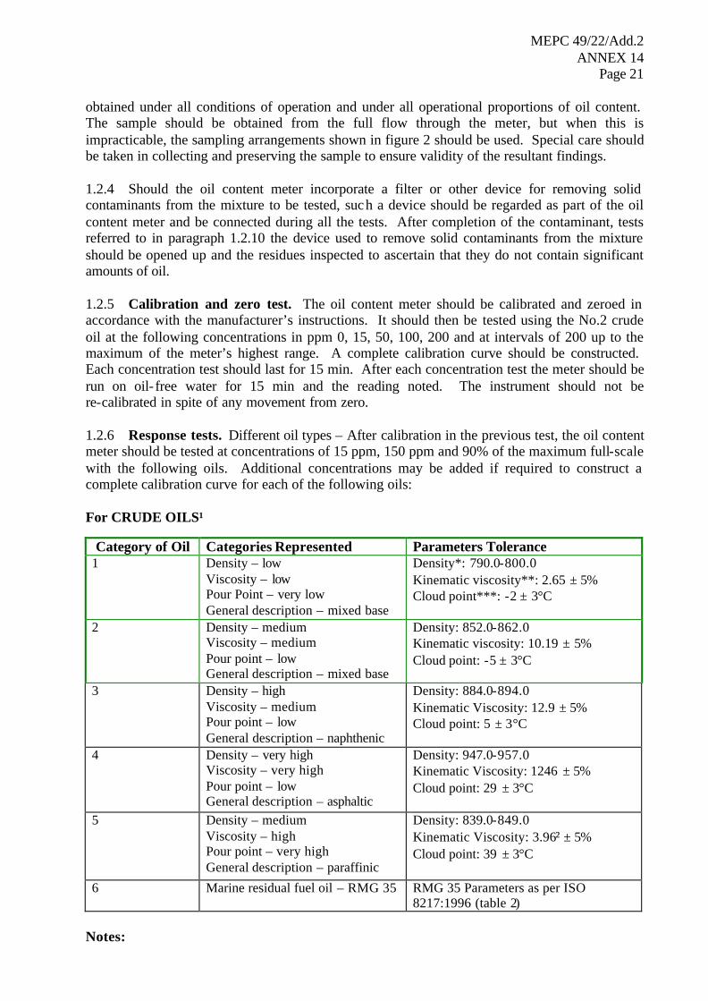
obtained under all conditions of operation and under all operational proportions of oil content. The sample should be obtained from the full flow through the meter, but when this is impracticable, the sampling arrangements shown in figure 2 should be used. Special care should be taken in collecting and preserving the sample to ensure validity of the resultant findings. 1.2.4 Should the oil content meter incorporate a filter or other device for removing solid contaminants from the mixture to be tested, such a device should be regarded as part of the oil content meter and be connected during all the tests. After completion of the contaminant, tests referred to in paragraph 1.2.10 the device used to remove solid contaminants from the mixture should be opened up and the residues inspected to ascertain that they do not contain significant amounts of oil. 1.2.5 Calibration and zero test. The oil content meter should be calibrated and zeroed in accordance with the manufacturer’s instructions. It should then be tested using the No.2 crude oil at the following concentrations in ppm 0, 15, 50, 100, 200 and at intervals of 200 up to the maximum of the meter’s highest range. A complete calibration curve should be constructed. Each concentration test should last for 15 min. After each concentration test the meter should be run on oil- free water for 15 min and the reading noted. The instrument should not be re-calibrated in spite of any movement from zero. 1.2.6 Response tests. Different oil types – After calibration in the previous test, the oil content meter should be tested at concentrations of 15 ppm, 150 ppm and 90% of the maximum full-scale with the following oils. Additional concentrations may be added if required to construct a complete calibration curve for each of the following oils: For CRUDE OILS¹
Category of Oil Categories Represented Parameters Tolerance 1 Density – low
Viscosity – low Pour Point – very low General description – mixed base
Density*: 790.0-800.0 Kinematic viscosity**: 2.65 ± 5% Cloud point***: -2 ± 3°C
2 Density – medium Viscosity – medium Pour point – low General description – mixed base
Density: 852.0-862.0 Kinematic viscosity: 10.19 ± 5% Cloud point: -5 ± 3°C
3 Density – high Viscosity – medium Pour point – low General description – naphthenic
Density: 884.0-894.0 Kinematic Viscosity: 12.9 ± 5% Cloud point: 5 ± 3°C
4 Density – very high Viscosity – very high Pour point – low General description – asphaltic
Density: 947.0-957.0 Kinematic Viscosity: 1246 ± 5% Cloud point: 29 ± 3°C
5 Density – medium Viscosity – high Pour point – very high General description – paraffinic
Density: 839.0-849.0 Kinematic Viscosity: 3.96² ± 5% Cloud point: 39 ± 3°C
6 Marine residual fuel oil – RMG 35 RMG 35 Parameters as per ISO 8217:1996 (table 2)
Notes:

MEPC 49/22/Add.2 ANNEX 14
Page 22
1 Reference for these parameters is Institute of Petroleum publication – Petroleum
Measurement Paper No. 8 – ISBN 0 85293 2. 2 This viscosity is recorded at 40ºC due to this oil’s high pour point which renders
the kinematic viscosity not measurable at 20ºC. * Density in kg/m3 at 15ºC; this parameter is reported by conversion using table 3 of
the Petroleum Measurement Tables – ASTM D 1250-80. ** Kinematic viscosity (Cst) at 20ºC. *** Cloud Point in ºC.
Note: Other oils covering the range of properties shown may be substituted if those shown are unobtainable.
The characteristics of the oil and age of sample shall be recorded. Samples used for approval must be less than 12 months old. Following each test, the meter should be run on oil- free water for 15 min and the meter reading recorded. Should the meter reading at zero oil through put exceed the accuracy requirement, an automatic cleaning device should be fitted to the instrument as standard. If it is necessary to re-zero, recalibrate, or clean the meter between tests, this fact and the time required to recalibrate or clean the meter should be noted and recorded on the certificate. 1.2.7 White petroleum products. If the meter is considered suitable for “white” petroleum products, it should also be tested with the following products in a manner similar to the tests set out in paragraphs 1.2.5 and 1.2.6: .1 Automotive gasoline; .2 Kerosene; and .3 Marine distillate fuel oil – DMA – ISO 8217: 1996 (table 1). If the meter is to be considered suitable for any of the category C and D oil- like noxious liquid substances referred to in the list contained in the unified interpretations to regulation 14 of Annex II of MARPOL 73/78, it should also be tested against each such substance for which approval is required, in a manner similar to the tests set out in paragraphs 1.2.5 and 1.2.6. The high shear pump shown in figure 1 should be kept in operation at high speed during this test to assist in dissolving the appropriate fraction of the substance in the water stream. 1.2.8 Response times. The oil content meter should be run on oil- free water and zeroed. The oil injection pump, set to 100 ppm No.2 crude oil, should be turned on. The following response times should be recorded and included on the certificate: .1 time for first detectable reading; .2 time to read 63 ppm;
.3 time to read 90 ppm; and .4 time to read 100 ppm or for reading to stabilize at maximum, the value (ppm) of
which should be recorded.

MEPC 49/22/Add.2 ANNEX 14
Page 23
Following this upscale test, the oil injection pump should be turned off and the following response times should be recorded and included on the certificate: .5 time for the maximum reading to drop detectably; .6 time to read 37 ppm; .7 time to read 10 ppm; and .8 time for reading to stabilize at minimum, the value (ppm) of which should be
recorded. The response time of the meter, which should be taken as the average of the response time recorded to read 63 ppm and the response time recorded to read 37 ppm, should be less than 20 s. 1.2.9 Oil fouling and calibration shift tests. Two tests using No.2 crude oil should be performed to determine the effect of oil fouling on calibration shift. The first test should be done with a 10% oil concentration and the second with a 100% oil concentration. For the 10% oil concentration test, the meter should initially be running on oil- free water. The high capacity oil injection pump, set to give 10% oil in water, should be turned on for 1 min and then turned off. For the 100% oil concentration test, the meter should be running on oil- free water. The water should be turned off and 100% oil turned on for 1 min. The oil should then be turned off and the oil- free water flow resumed. Care must be taken in the design of the test equipment to ensure that the oil fouling test results are not degraded by fouling of the sample piping external to the meter. The following response times should be noted for both tests and recorded on the certificate: .1 time for first detectable reading; .2 time to read 15 ppm; .3 time to read 100 ppm; .4 time for reading to go off scale on the highest range; .5 time for reading to return back on scale on the highest range; .6 time for reading to return to 100 ppm; .7 time for reading to return to 15 ppm; and .8 time for reading to return to zero or stabilize at minimum ppm reading. If it is necessary to clean the meter after each oil fouling test for it to return to a zero reading, this fact and the time required to clean and recalibrate the meter sha ll be noted and recorded on the certificate.

MEPC 49/22/Add.2 ANNEX 14
Page 24
After successful completion of both oil fouling tests, a 100 ppm mixture of No.2 crude oil should be introduced and any calibration shift noted and recorded on the certificate. 1.2.10 Contaminant tests. The meter should be run on contaminant test as follows: .1 the contaminants should be mixed in the mixing tank with clean water as follows:
not less than 270 ppm by weight of attapulgite (see note (a)) and 30 ppm by weight of iron oxides (see note (b)). Each material should be mixed sequentially in the mixing tank to the following criteria:
.1.1 attapulgite for a period of not less than 15 min so that a homogenous
suspension is formed; iron oxides for an additional period of not less than 10 min. The mixing process should maintain the contaminants in suspension throughout the test period;
.2 the meter should be run on a mixture of clean water and No.2 crude oil of 15 ppm; .3 the water supply should be changed from clean water to contaminated water;
.4 any shift in the meter reading should be noted in the certificate. The meter reading should be within the accuracy limits specified in 1.2.1;
.5 the test specified in .2, .3, and .4 above, should be repeated with oil concentrations
of 100 ppm and 300 ppm; and .6 sufficient water should be available in the mixing tanks to ensure an effective test
period of not less than 15 min. Notes: (a) Attapulgite is a clay mineral with the chemical formula (MgAl)5Si8O22(OH)44H2O
and is stable in both fresh and salt water. The test contaminant should have a particle size distribution with about 30% of 10 microns or less and a maximum particle size of 100 microns.
(b) The term “iron oxides” is used to describe black ferrosoferric oxide (Fe3O4) with a
particle size distribution of which 90% is less than 10 microns, the remainder having a maximum particle size of 100 microns.
1.2.11 Air entrainment test .1 The meter should be run on a mixture of water and 15 ppm No.2 crude oil.
.2 Air should be injected into the test circuit immediately before the sample pump or, in the absence of such pump, immediately before any conditioning unit used to prepare the mixture for measurement. Injection should be by needle having an orifice dimension not exceeding 0.5 mm in diameter arranged in line with the sample flow. The quantity of air injected should be 1% of the designated flow rate of the sample pump or conditioning unit at the point of injection. Air should be delivered to the system by direct injection or pump via a suitable measuring device designed to permit a constant controllable flow rate within +10% of the required rate of injection for an uninterrupted effective test period of not less than 15 min.

MEPC 49/22/Add.2 ANNEX 14
Page 25
.3 Any shift in the meter reading should be recorded on the certificate. .4 The tests specified in points 1, 2 and 3 should be repeated with an oil
concentration of 100 ppm and 300 ppm respectively. 1.2.12 Oil particle size - shear pump test. The meter should be run on a mixture of water and No. 2 crude oil of 100 ppm. The high shear pump, shown in figure 1, should be run at various speeds to provide a range of oil particle size to the meter and on completion of this test the pump should be stopped. Any effect of particle size on the meter reading should be noted and recorded on the certificate. The purpose of this test is to demonstrate that the meter’s accuracy is not significantly affected by the oil droplet size or by the degree of oil and water mixing. 1.2.13 Temperature test. The meter should be run on a mixture of water and No.2 crude oil of 100 ppm. The water temperature should initially be set at 10oC and then at 65oC. If the manufacturer’s specification lists an operating maximum water temperature of less than 65oC,the meter should be run at that maximum temperature and this fact, together with any effect of water temperature on the meter reading, should be recorded on the certificate. 1.2.14 Sample pressure or flow test. The meter should be run on a mixture of water and No.2 crude oil of 100 ppm. The water pressure or flow rate of the mixture should be adjusted from one-half normal, to normal and to twice normal. Any effect of these changes on the meter reading should be recorded on the certificate. This test may require modification, depending on the flow characteristics of the meter. 1.2.15 Shut-off test. The meter should run on a mixture of water and No.2 crude oil of 100 ppm. The water and oil injection pumps should be shut off and the meter left on with no other changes made. After eight hours, the water and the oil injection pumps should be turned on and set to provide a mixture of 100 ppm. The meter readings before and after each test and any damage to the meter should be recorded on the certificate. This test also determines the proper functioning of the low flow shut-off and alarm. 1.2.16 Utility supply variation test. The meter should be run on a mixture of water and No.2 crude oil of 100 ppm. The supply voltage should be increased to 110% of the nominal value for one hour and then reduced to 90% of the nominal value for one hour. Any effect on meter performance should be recorded on the certificate. If the operation of the meter requires any utilities besides electricity, it should be tested with these utilities at 110% and 90% of the design figures. 1.2.17 Calibration and zero drift test. The meter should be calibrated and zeroed in accordance with the procedures in the manufacturer’s instructions manual. A mixture of water and No.2 crude oil of 100 ppm should be run through the meter for eight hours and any calibration drift recorded on the certificate. Following this, the meter should be run on oil- free water and any zero drift recorded on the certificate. 1.2.18 Shut-down and re-energization test. The meter should be shut down and de-energized for one week. It should be turned on and started in accordance with the manufacturer’s instructions. After the suggested warm-up and calibration procedures, the meter should be run for a period of eight hours, operating alternatively for one hour on a mixture of water and No.2 crude oil of 100 ppm and for one hour on oil- free water. After each step in the operation, any zero or span drift should be recorded on the certificate. The total time required to perform the

MEPC 49/22/Add.2 ANNEX 14
Page 26
manufacturer’s suggested warm-up and calibration should also be recorded on the certificate. 1.2.19 Reporting of test results. A specification of the instrument concerned and a diagrammatic presentation of the test arrangements should be provided to the Administration by the manufacturer when applying for type approval and the following data should be reported in the international metric system of units: .1 types and properties of oils used in the tests; .2 details of contaminants used, in the form, for example, of a supplier’s certificate
or laboratory test protocol; and .3 results of tests and analysis of grab samples. The recommendations of the manufacturer of the oil content meter concerning the choice and application of cleansing agents used for cleaning purpose should be recorded in the appendix to the type approval certificate.
Figure 1 – Test rig
The size of the mixing tank should be specified so as to allow a minimum “once through” effective test period of 15 min. Adequate arrangements should be made for in-tank mixing or recycling to ensure a homogeneous mixture.

MEPC 49/22/Add.2 ANNEX 14
Page 27
A Distance A, not greater than 400 mm B Distance B, sufficient to insert sample bottle C Dimension C, straight length should not be less than 60 mm D Dimension D, pipe thickness should not be greater than 2 mm E Detail E, chisel-edged chamfer (30º)
Figure 2 – Alternative sampling arrangement in test rig
1.3 Method for the determination of oil content The determination of the oil content will be performed according to the International Standard ISO 9377-2:2000 “Water quality – Determination of hydrocarbon oil index – Part 2: Method using solvent extraction and gas chromatography” that specifies a method for sampling and subsequent determination of the hydrocarbon oil index in water using solvent extraction and gas chromatography. This method should be used for the determination of oil content requirements outlined in these Guidelines and Specifications. PART 2 – SPECIFICATION FOR ENVIRONMENTAL TESTING FOR TYPE
APPROVAL OF THE OIL CONTENT METER AND THE CONTROL SECTION OF AN OIL DISCHARGE MONITORING AND CONTROL SYSTEM
2.1 General 2.1.1 The specification for environmental testing for type approval relates to the electronic section of the oil content meter and the control section of a monitoring and control system. A control section may be an independent unit or be combined with the electronic part of the oil content meter.
2.1.2 The equipment tested should comply with all the relevant requirements contained in section 5 of the Guidelines and Specifications.

MEPC 49/22/Add.2 ANNEX 14
Page 28
2.2 Test specifications
2.2.1 Testing requirements
The electrical and electronic section of the oil content meter and the control section of the monitoring system in the standard production configuration should be subjected to the programme of environmental tests set out in this specification at a laboratory approved for the purpose by the Administration or by the competent authority of the manufacturer’s home country. A copy of the environmental test document, in a format similar to that specified in paragraph 3.2 of this specification, should be submitted to the Administration by the manufacturer together with the application for type approval. 2.2.2 Test specification details Equipment should operate satisfactorily on completion of each of the following environmental tests:
.1 Vibration tests .1.1 a search should be made for resonance over the following range of
frequency and amplitude or acceleration: .1.1.1 2 to 13.2 Hz with an amplitude of +1 mm; and .1.1.2 13.2 to 80 Hz with an acceleration of +0.7 g;
This search should be made in each of the three planes at a rate sufficiently low to permit detection of resonance;
.1.2 the equipment should be vibrated in the planes at each major resonant
frequency for a period of two hours; .1.3 if there is no resonant frequency, the equipment should be vibrated in each
of the plans at 30 Hz with an acceleration of +0.7 g for a period of two hours;
.1.4 after completion of the tests specified in .1.2 or .1.3 of this paragraph a
search should again be made for resonance and there should be no significant change in the vibration pattern;
.2 Temperature tests .2.1 Equipment that may be installed in exposed areas on the open deck or in
an enclosed space not environmentally controlled should be subjected, for a period of not less than two hours, to:
.2.1.1 a low temperature test at –25oC; and .2.1.2 a high temperature test at 55oC;

MEPC 49/22/Add.2 ANNEX 14
Page 29
.2.2 Equipment that may be installed in an enclosed space that is environmentally controlled including an engine-room, should be subjected, for a period of not less than two hours, to:
.2.2.1 a low temperature test at 0oC; and .2.2.2 a high temperature test at 55oC;
At the end of each of the tests referred to in this subparagraph above, the equipment should be switched on and it should function normally under the test conditions;
.3 Humidity tests
Equipment should be left switched off for a period of two hours at a temperature of 55oC in an atmosphere with a relevant humidity of 90%. At the end of this period, the equipment should be switched on and should operate satisfactorily for one hour;
.4 Tests for protection against heavy seas
Equipment that may be installed in exposed areas on the open deck shall be subjected to tests for protection against heavy seas in accordance with lP 56 of IEC publication 529 or its equivalent;
.5 Fluctuation in power supply .5.1 Equipment should operate satisfactorily with: .5.1.1 a voltage variation of +10% together with a simultaneous
frequency variation of +5%; .5.1.2 a transient voltage of +20% together with a simultaneous frequency
transient of +10%, with a transient recovery time of three seconds; .6 Inclination test
Equipment should operate satisfactorily at angles of inclination up to 22.5oC in any plane from the normal operating position;
.7 Reliability of electrical and electronic equipment
The electrical and electronic components of the equipment should be of a quality guaranteed by the manufacturer and suitable for their intended purpose.
PART 3 – DOCUMENTATION OF APPROVAL
3.1 Certificate of type approval for oil content meters
3.1.1 Satisfactory compliance with all the test requirements enumerated in part 1 of this annex should be shown in the certificate of type approval issued by the Administration in the format specified in paragraph 3.1.2 below. An Administration may issue a certificate of type approval

MEPC 49/22/Add.2 ANNEX 14
Page 30
based on separate testing or on testing already carried out under supervision by another Administration.
3.1.2 A certificate of type approval should be in the format shown in the appendix to this annex. The certificate should identify the type and model of the oil content meter to which it applies and identify equipment assembly drawings, duly dated. Each drawing should bear the model specification numbers or equivalent identification details. The certificate should include the full performance test protocol on which it is based. If a certificate of type approval is issued by an Administration based on a certificate previously issued by another Administration, the certificate should identify the Administration which conducted the tests on the oil content meter and a copy of the original test should be attached to it.
3.2 Format of environmental test protocol
3.2.1 Satisfactory compliance with the environmental tests laid down in these Guidelines and Specifications, where applicable, should be shown on the environmental test protocol issued by the testing laboratory. The protocol should include at least the following details:
.1 identification of the equipment by type and drawing number, duly dated; and .2 a statement of the tests conducted on the equipment, including the results thereof.
3.2.2 The environmental test protocol should be endorsed by either the Administration or a competent authority of the manufacturer’s home country to confirm that the laboratory is approved to conduct such tests. The protocol should also be signed and dated by the person in charge of the laboratory.

MEPC 49/22/Add.2 ANNEX 14
Page 31
APPENDIX
NAME OF ADMINISTRATION
CERTIFICATE OF TYPE APPROVAL FOR OIL CONTENT METERS INTENDED FOR MONITORING THE DISCHARGE OF OIL-CONTAMINATED WATER FROM
THE CARGO TANK AREAS OF OIL TANKERS
This is to certify that the oil content meter, comprising the equipment listed below, has been examined and tested in accordance with the requirements of the specification contained in part 1 of the annex to the Guidelines and Specifications contained in IMO resolution MEPC.108(49). This certificate is valid only for an oil content meter referred to below.
Oil content meter supplied by ……………………………………………………………………. under type and model designation …………………………………………………………..…… and incorporating:
Oil content meter analysing unit manufactured by ………………………………………………. to specification /assembly drawing No. . …………..date ……………………………….………. Electronic section of oil content meter manufactured by ………………………………………… to specification/assembly drawing No. ………….…date ………………………………………...
*Sample feed pump manufactured by .………………………………………….………………… to specification/assembly drawing No. . ……………date …………………………..………….... *Sample conditioning unit manufactured by ……………………………………….……………. to specification/assembly drawing No. ….…………date ……………………………....…….…. The oil content meter is acceptable for the following applications: *Crude oils * ”Black" products * "White" products * Oil-like noxious liquid substances, other products, or applications, listed below A copy of this certificate should be carried aboard a ship fitted with this equipment at all times. Test data and results attached as appendix.
Signed . …………………………………………….
Official stamp Administration of………………………………….. Dated this ……………….….. day of….……. 20…
* Delete as appropriate.
Badge or
Cipher

MEPC 49/22/Add.2 ANNEX 14
Page 32
APPENDIX
TEST DATA AND RESULTS OF TESTS CONDUCTED ON AN OIL CONTENT METER IN ACCORDANCE WITH PART 1
OF THE ANNEX TO THE GUIDELINES AND SPECIFICATIONS CONTAINED IN IMO RESOLUTION MEPC.108(49)
Oil content meter submitted by……………………………………………………………………… Test location …………………………………………………………………………..………… Method of sample analysis …………………………………………….………………………… Samples analysed by…………………………………………………….…………………… Environmental testing of the electronic section of the oil content meter has been carried out in accordance with part 2 of the annex to the Guidelines and Specifications contained in IMO resolution MEPC.108(49). The equipment functioned satisfactorily on completion of each test specified on the environmental test protocol.

MEPC 49/22/Add.2 ANNEX 14
Page 33
READINGS (ppm)
Indicated Measured Grab
sample
REMARKS
CALIBRATION 0 …………… …………… ……………
15 …………… …………… ……………
50 …………… …………… ……………
100 …………… …………… ……………
200 …………… …………… ……………
400 …………… …………… ……………
600 …………… …………… …………… TEST
800 …………… …………… …………… WATER TEMPERATURE ºC
1000 …………… …………… …………… RE-ZERO YES/NO*
…………… …………… …………… YES/NO*
OIL TYPE
RESPONSE TESTS
No.1 crude oil 15 …………… …………… ……………
100 …………… …………… ……………
90% M.F.S.V. = …………… …………… ……………
RECORDED ZERO …………… RE-ZERO YES/NO*
TIME mins
RECALIBRATE YES/NO*
TIME mins
CLEAN YES/NO*
TIME mins
No.2 crude oil 15 …………… …………… ……………
100 …………… …………… ……………
90% M.F.S.V. = …………… …………… ……………
RECORDED ZERO …………… RE-ZERO YES/NO*
TIME mins
RECALIBRATE YES/NO*
TIME mins
M.F.S.V. = MAXIMUM CLEAN YES/NO*
FULL SCALE VALUE TIME mins
* Delete as appropriate.

MEPC 49/22/Add.2 ANNEX 14
Page 34
READINGS (ppm)
Indicated Measured Grab
sample
REMARKS
…………… …………… ……………
No.3 crude oil 15 …………… …………… ……………
100 …………… …………… ……………
90% M.F.S.V. = …………… …………… ……………
RECORDED ZERO …………… RE-ZERO YES/NO∗
TIME mins
RECALIBRATE YES/NO*
TIME mins
CLEAN YES/NO*
…………… …………… …………… TIME mins
No.4 crude oil 15 …………… …………… ……………
100 …………… …………… ……………
90% M.F.S.V. = …………… …………… ……………
RECORDED ZERO …………… RE-ZERO YES/NO*
TIME mins
RECALIBRATE YES/NO*
TIME mins
CLEAN YES/NO*
TIME mins
No.5 crude oil 15 …………… …………… ……………
100 …………… …………… ……………
90% M.F.S.V. = …………… …………… ……………
RECORDED ZERO …………… RE-ZERO YES/NO*
TIME mins
RECALIBRATE YES/NO*
TIME mins
CLEAN YES/NO*
TIME mins
∗ Delete as appropriate.

MEPC 49/22/Add.2 ANNEX 14
Page 35
READINGS (ppm)
Indicated Measured Grab
sample
REMARKS
Marine residual fuel oil
…………… …………… ……………
15 …………… …………… ……………
RMG 35- ISO 8217 100 …………… …………… ……………
90% M.F.S.V. = …………… …………… ……………
RECORDED ZERO …………… RE-ZERO YES/NO∗
TIME mins
RECALIBRATE YES/NO*
TIME mins
CLEAN YES/NO*
…………… …………… …………… TIME mins
Automotive gasoline
15 …………… …………… ……………
100 …………… …………… ……………
90% M.F.S.V. = …………… …………… ……………
RECORDED ZERO …………… RE-ZERO YES/NO*
TIME mins
RECALIBRATE YES/NO*
TIME mins
CLEAN YES/NO*
TIME mins
∗ Delete as appropriate.
MEPC 49/22/Add.2 ANNEX 14
Page 36
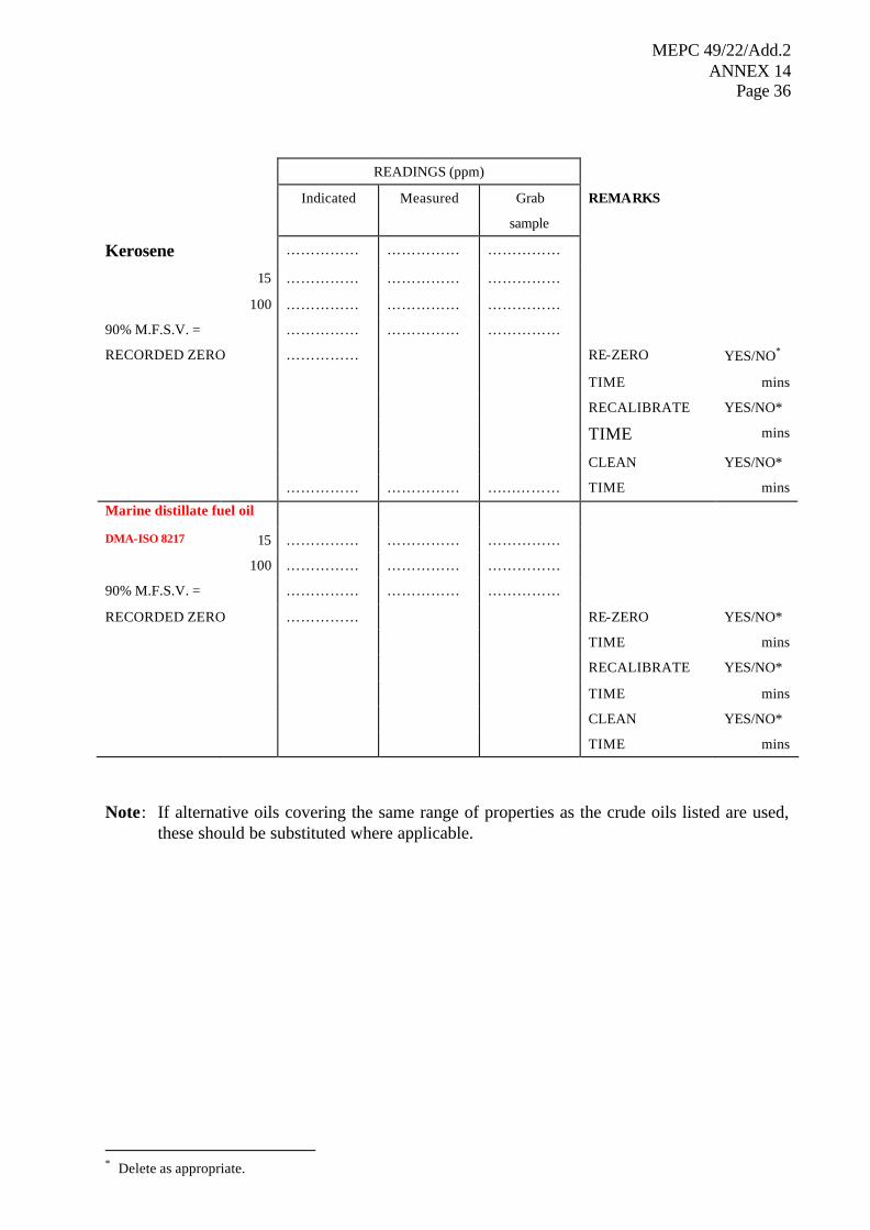
READINGS (ppm)
Indicated Measured Grab
sample
REMARKS
Kerosene …………… …………… ……………
15 …………… …………… ……………
100 …………… …………… ……………
90% M.F.S.V. = …………… …………… ……………
RECORDED ZERO …………… RE-ZERO YES/NO∗
TIME mins
RECALIBRATE YES/NO*
TIME mins
CLEAN YES/NO*
…………… …………… …………… TIME mins
Marine distillate fuel oil
DMA-ISO 8217 15 …………… …………… ……………
100 …………… …………… ……………
90% M.F.S.V. = …………… …………… ……………
RECORDED ZERO …………… RE-ZERO YES/NO*
TIME mins
RECALIBRATE YES/NO*
TIME mins
CLEAN YES/NO*
TIME mins
Note: If alternative oils covering the same range of properties as the crude oils listed are used, these should be substituted where applicable.
∗ Delete as appropriate.

MEPC 49/22/Add.2 ANNEX 14
Page 37
OIL-LIKE NOXIOUS LIQUID SUBSTANCES, OTHER PRODUCTS OR APPLICATIONS∗
READINGS (ppm)
Indicated Measured Grab
sample
REMARKS
Name of product …………… …………… ……………
………………… 15 …………… …………… ……………
100 …………… …………… ……………
90% M.F.S.V. = …………… …………… ……………
RECORDED ZERO …………… RE-ZERO YES/NO∗∗
TIME mins
RECALIBRATE YES/NO**
TIME mins
CLEAN YES/NO**
…………… …………… …………… TIME mins
Name of product
………………… 15 …………… …………… ……………
100 …………… …………… ……………
90% M.F.S.V. = …………… …………… ……………
RECORDED ZERO …………… RE-ZERO YES/NO**
TIME mins
RECALIBRATE YES/NO**
TIME mins
CLEAN YES/NO**
TIME mins
∗ This page should be included in the certificate only if the oil content meter has been tested against category C or D
oil-like noxious liquid substances. ∗∗ Delete as appropriate.

MEPC 49/22/Add.2 ANNEX 14
Page 38
RESPONSE TIMES seconds
First detectable reading
63 ppm
………………………
………………………?
90 ppm …………………………
Stabilized maximum reading or 100 ppm ….. ppm ………………………
First detectable drop …………………………
37 ppm ………………………?
10 ppm …………………………
Stabilized minimum reading ….. ppm ………………………
RESPONSE TIME = ? +? 2
= ………………………

MEPC 49/22/Add.2 ANNEX 14
Page 39
∗ Delete as appropriate.
OIL FOULING AND CALIBRATION SHIFT seconds 10% oil concentration test
First detectable response
15 ppm
100 ppm
…………………………
…………………………
…………………………
Off scale on highest range ………………………
On scale on highest range
100 ppm
15 ppm
…………………………
…………………………
…………………………
Minimum reading ….. ppm ………………………
Further cleaning required YES/NO∗ (State extent)
Time …………. mins
100% oil concentration test seconds
First detectable response
15 ppm
100 ppm
…………………………
…………………………
………………………..
Off scale on highest range ………………………
On scale on highest range
100 ppm
15 ppm
…………………………
…………………………
…………………………
Minimum reading ….. ppm ………………………
Further cleaning required YES/NO* (State extent)
Time …………. mins
Calibration shift ….. ppm

MEPC 49/22/Add.2 ANNEX 14
Page 40
CONTAMINANT TEST
Meter reading shift with 300 ppm non-oil contaminants mixed with water and No.2 crude oil in oil concentrations of:
- 15 ppm ..............ppm - 100 ppm ..............ppm - 300 ppm ..............ppm
AIR ENTRAINMENT TEST
Meter reading shift with 1% air entrained in water and No.2 crude oil added in concentrations of:
- 15 ppm ..............ppm - 100 ppm ..............ppm - 300 ppm ..............ppm
OIL PARTICLE SIZE TEST
Meter reading shift ..............ppm
TEMPERATURE TEST
Calibration test water temperature .............. ºC Meter reading shift at 10°C ..............ppm Meter reading shift at 65°C ..............ppm
SAMPLE PRESSURE OR FLOW TEST
Meter reading shift at 50° of normal ..............ppm Meter reading shift at 200° of normal ..............ppm Deviations from this test should be stated if necessary
SHUT-OFF TEST
Meter reading before shut off ..............ppm Meter reading after start-up (minimum dry period 8 hours) ..............ppm Damage to meter as follows:
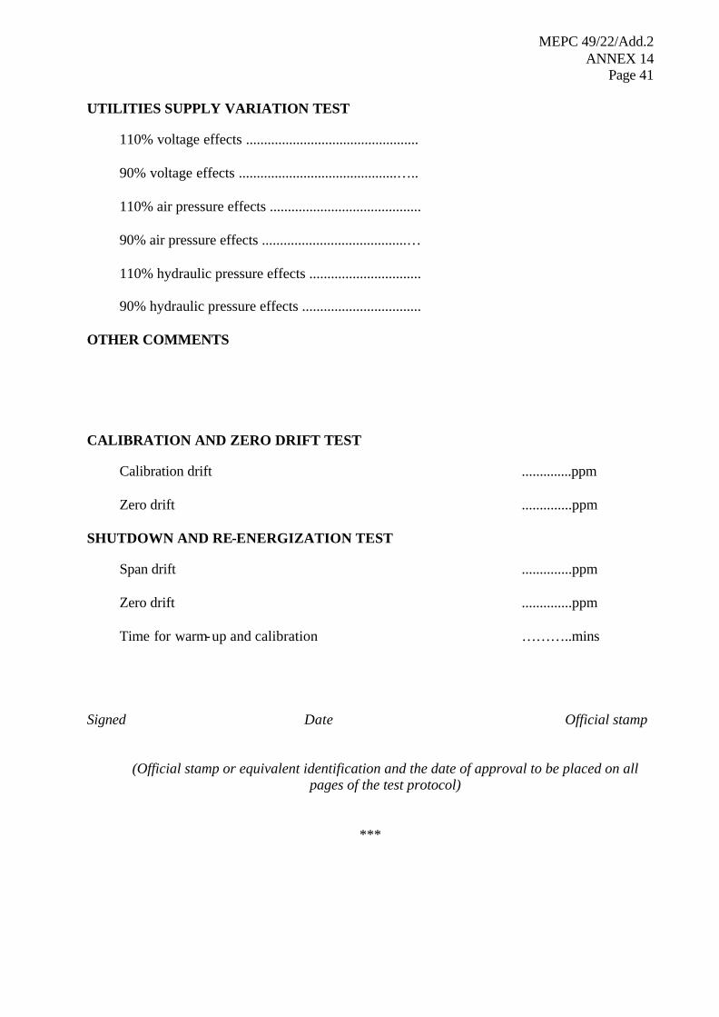
MEPC 49/22/Add.2 ANNEX 14
Page 41
UTILITIES SUPPLY VARIATION TEST
110% voltage effects ................................................ 90% voltage effects ............................................….. 110% air pressure effects .......................................... 90% air pressure effects ........................................… 110% hydraulic pressure effects ............................... 90% hydraulic pressure effects .................................
OTHER COMMENTS CALIBRATION AND ZERO DRIFT TEST
Calibration drift ..............ppm Zero drift ..............ppm
SHUTDOWN AND RE-ENERGIZATION TEST
Span drift ..............ppm Zero drift ..............ppm Time for warm-up and calibration ………..mins
Signed Date Official stamp
(Official stamp or equivalent identification and the date of approval to be placed on all pages of the test protocol)
***

MEPC 49/22/Add.2 ANNEX 14
Page 42
MEPC 65/22/Add.1 Annex 30, page 1
I:\MEPC\65\22-Add-1.doc
ANNEX 30
RESOLUTION MEPC.240(65)
Adopted on 17 May 2013
2013 AMENDMENTS TO THE REVISED GUIDELINES AND SPECIFICATIONS FOR OIL DISCHARGE MONITORING AND CONTROL SYSTEMS FOR
OIL TANKERS (RESOLUTION MEPC.108(49)) THE MARINE ENVIRONMENT PROTECTION COMMITTEE, RECALLING Article 38(a) of the Convention on the International Maritime Organization concerning the functions of the Marine Environment Protection Committee conferred upon it by international conventions for the prevention and control of marine pollution, NOTING resolution MEPC.108(49) by which the Committee adopted the Revised Guidelines and Specifications for Oil Discharge Monitoring and Control Systems for Oil Tankers, NOTING ALSO that the revised MARPOL Annex I was adopted by resolution MEPC.117(52) and entered into force on 1 January 2007, HAVING CONSIDERED, at its sixty-fifth session, proposed amendments to the Revised Guidelines and Specifications for Oil Discharge Monitoring and Control Systems for Oil Tankers, prepared by the Sub-Committee on Bulk Liquids and Gases at is seventeenth session, 1. ADOPTS the 2013 Amendments to the Revised Guidelines and Specifications for Oil Discharge Monitoring and Control Systems for Oil Tankers, the text of which is set out in the annex to this resolution; 2. RECOMMENDS Governments to apply the annexed amendments when approving oil discharge monitoring and control systems being installed under regulation 31 of MARPOL Annex I on oil tankers constructed on or after 1 January 2005.
* * *

MEPC 65/22/Add.1 Annex 30, page 2
I:\MEPC\65\22-Add-1.doc
ANNEX
2013 AMENDMENTS TO THE REVISED GUIDELINES AND SPECIFICATIONS FOR OIL DISCHARGE MONITORING AND CONTROL SYSTEMS FOR OIL TANKERS
REVISED GUIDELINES AND SPECIFICATIONS FOR OIL DISCHARGE MONITORING AND CONTROL SYSTEMS FOR OIL TANKERS 1 In the Table of Contents, a new entry 3.7 is added, as follows: "3.7 Bio-fuels" 2 In paragraphs 1.1.1 and 1.1.2.1, the references "regulation 15(3)(a) of Annex I of MARPOL" are replaced by the references "regulation 31 of MARPOL Annex I. 3 Paragraph 1.1.3 is replaced by the following:
"1.1.3 These Guidelines and Specifications also apply to oil content monitoring systems used for monitoring each individual bio-fuel blend containing 75 per cent or more of petroleum oil, carried in accordance with paragraph 4.1 of MEPC.1/Circ.761. Wherever in these Guidelines and Specifications reference is made to oil being monitored, this applies likewise to bio-fuel blends."
4 In paragraph 2.1, the references "Annex I of MARPOL" and "regulation 15(3)(a)" are replaced by the references "MARPOL Annex I " and "regulation 31", respectively. 5 In paragraph 2.2, the references "regulation 15" and "regulation 9(1)(a)" are replaced by the references "regulation 31" and "regulation 34.1", respectively. 6 In section 3, a new definition is added, as follows: "3.7 Bio-fuels
Bio-fuels are products as recorded in annex 11 of the MEPC.2/Circular which are intended for blending with petroleum oil and may be shipped as blends in accordance with MEPC.1/Circ.761, as amended."
7 A new paragraph 5.7 is added, as follows: "5.7 Manufacturer recommended spares for the ODME should be carried to
ensure the operation of the equipment." 8 The existing paragraph 5.7 is renumbered as paragraph 5.8. 9 In paragraph 6.1.1, the reference "regulation 18" is replaced by the reference "regulation 30". 10 The footnote associated with paragraph 6.1.6 is replaced by the following:
" As specified in IEC publication 92 or an equivalent standard acceptable to the administration."
11 In paragraph 6.8.2, the references "regulation 9(1)(a)(iv) and (v)" are replaced by the references "regulation 31.1.4 and 31.1.5".
MEPC 65/22/Add.1 Annex 30, page 3
I:\MEPC\65\22-Add-1.doc
12 The chapeau of paragraph 6.11.1 and subparagraph .1 is replaced by the following: "6.11.1 The alternative means of obtaining information in the event of a failure in
the monitoring system should follow the requirements in MARPOL Annex I, regulation 31.4 and the operational manual as approved by the Administrations and should be as follows:
.1 oil content meter or sampling system: location and measurement of the
oil/water interface using the equipment as required in regulation 32, visual observation of the surface of the water adjacent to the effluent discharge and recording the relevant data for the discharge accurately in the Oil Record Book Part II in sections H and I;".
13 In the footnote associated with subparagraph 6.12.2, the reference "regulation 9(1)(a)(5)" is replaced by the reference "regulation 34.1.5". 14 In paragraph 7.2.2, after the words "white products", insert the words ", individual biofuel blends". 15 In subparagraph 8.3.3, the references "regulations 9(1)(a)(iv) and (v)" are replaced by the references "regulations 34.1.4 and 34.1.5". ANNEX, PART 1 – TEST AND PERFORMANCE SPECIFICATIONS FOR TYPE APPROVAL OF OIL CONTENT METERS 16 In the table under paragraph 1.2.6, under the column "Parameters Tolerance" and row "6", the text "RMG 35 Parameters as per ISO 8217:1996 (table 2)" is replaced by the following text: "RMG 35 Parameters as per ISO 8217:2010/Corr 1:2011 (tables 1 and 2)" 17 In paragraph 1.2.7, the reference standard "ISO 8217:1996 (table 1)" is replaced by the referenced standard "ISO 8217:2010/Corr 1:2011 (tables 1 and 2)". 18 New paragraph 1.2.8 is added, as follows:
"1.2.8 If the meter is to be considered suitable for an individual biofuel blend containing 75 per cent or more of petroleum oil, it should also be tested against each such substance for which approval is required, in a manner similar to the tests set out in paragraphs 1.2.5 and 1.2.6. The high shear pump shown in figure 1 should be kept in operation at high speed during this test to assist in dissolving the appropriate fraction of the substance in the water stream."
19 New paragraph 1.2.9 is added, as follows: "1.2.9 Individual Biofuel blends should be tested at 75 per cent and 99 per cent
petroleum oil." 20 The existing paragraphs 1.2.8 to 1.2.19 are renumbered as paragraphs 1.2.10 to 1.2.21.
MEPC 65/22/Add.1 Annex 30, page 4
I:\MEPC\65\22-Add-1.doc
APPENDIX, CERTIFICATE OF TYPE APPROVAL FOR OIL CONTENT METERS INTENDED FOR MONITORING THE DISCHARGE OF OIL-CONTAMINATED WATER FROM THE CARGO TANK AREAS OF OIL TANKERS 21 Under the "The oil content meter is acceptable for the following applications:", the text "*Oil-like noxious liquid substances, other products, or applications, listed below" is replaced by the following:
"* Individual biofuel blends containing 75 per cent or more of petroleum oil, other products, or applications, listed below"
APPENDIX, TEST DATA AND RESULTS OF TESTS CONDUCTED ON AN OIL CONTENT METER IN ACCORDANCE WITH PART 1 OF THE ANNEX TO THE GUIDELINES AND SPECIFICATIONS CONTAINED IN IMO RESOLUTION MEPC.108(49)
22 The table for "OIL LIKE noxious liquid substances, other products or applications" is deleted, and tables for "INDIVIDUAL BIOFUEL BLENDS AND CONCENTRATIONS" and "OTHER PRODUCTS OR APPLICATIONS" are added, as follows:

MEPC 65/22/Add.1 Annex 30, page 5
I:\MEPC\65\22-Add-1.doc
INDIVIDUAL BIOFUEL BLENDS AND CONCENTRATIONS
READINGS (ppm)
Indicated Measured Grab sample
REMARKS
Bio-Fuel Blend 75% Petroleum Oil
…………… …………… ……………
Name of Bio-fuel and petroleum oil components
………………… % …………………. % ………………… 15 …………… …………… …………… 100 …………… …………… …………… 90% M.F.S.V. = …………… …………… …………… RECORDED ZERO …………… RE-ZERO YES/NO
TIME mins RECALIBRATE YES/NO
**
TIME mins CLEAN YES/NO
**
…………… …………… …………… TIME mins
Bio-Fuel Blend 99% Petroleum Oil
Name of Bio-fuel and petroleum oil components
………………… % …………………. % ………………… 15 …………… …………… …………… 100 …………… …………… …………… 90% M.F.S.V. = …………… …………… …………… RECORDED ZERO …………… RE-ZERO YES/NO** TIME mins RECALIBRATE YES/NO** TIME mins CLEAN YES/NO** TIME mins
This page should be included in the certificate only if the oil content meter has been tested against bio-fuel
blends.
Delete as appropriate.
RESPONSE TIMES Seconds First detectable reading
63 ppm …………………………. ………………………….1
90 ppm …………………………. Stabilized maximum reading or 100
ppm ….. ppm ………………………….
First detectable drop ………………………… 37 ppm …………………………2 10 ppm ………………………… Stabilized minimum reading ….. ppm ………………………… RESPONSE TIME = 1+ 2
2
= …………………………

MEPC 65/22/Add.1 Annex 30, page 6
I:\MEPC\65\22-Add-1.doc
OTHER PRODUCTS OR APPLICATIONS
READINGS (ppm)
Indicated Measured Grab sample
REMARKS
Name of product …………… …………… ……………
………………… 15 …………… …………… …………… 100 …………… …………… …………… 90% M.F.S.V. = …………… …………… …………… RECORDED ZERO …………… RE-ZERO YES/NO TIME Mins RECALIBRATE YES/NO** TIME Mins CLEAN YES/NO** …………… …………… …………… TIME Mins
Name of product
………………… 15 …………… …………… …………… 100 …………… …………… …………… 90% M.F.S.V. = …………… …………… …………… RECORDED ZERO …………… RE-ZERO YES/NO** TIME Mins RECALIBRATE YES/NO** TIME Mins CLEAN YES/NO** TIME Mins
***
This page should be included in the certificate only if the oil content meter has been tested against other
products and applications substances. Delete as appropriate.