
MEPC 73/19/Add.1 ANNEX 5 RESOLUTION MEPC.308(73 ...
36
MEPC 73/19/Add.1 Annex 5, page 1 I:\MEPC\73\MEPC 73-19-Add-1.docx ANNEX 5 RESOLUTION MEPC.308(73) (adopted on 26 October 2018) 2018 GUIDELINES ON THE METHOD OF CALCULATION OF THE ATTAINED ENERGY EFFICIENCY DESIGN INDEX (EEDI) FOR NEW SHIPS THE MARINE ENVIRONMENT PROTECTION COMMITTEE, RECALLING article 38(a) of the Convention on the International Maritime Organization concerning the functions of the Marine Environment Protection Committee (the Committee) conferred upon it by international conventions for the prevention and control of marine pollution from ships, RECALLING ALSO that it adopted, by resolution MEPC.203(62), Amendments to the annex of the Protocol of 1997 to amend the International Convention for the Prevention of Pollution from Ships, 1973, as modified by the Protocol of 1978 relating thereto (inclusion of regulations on energy efficiency for ships in MARPOL Annex VI), NOTING that the aforementioned amendments to MARPOL Annex VI entered into force on 1 January 2013, NOTING ALSO that regulation 20 (Attained Energy Efficiency Design Index (attained EEDI)) of MARPOL Annex VI, as amended, requires that the EEDI shall be calculated taking into account the guidelines developed by the Organization, NOTING FURTHER that the 2012 Guidelines on the method of calculation of the attained Energy Efficiency Design Index (EEDI) for new ships, adopted by resolution MEPC.212(63), and, the amendments thereto, adopted by resolution MEPC.224(64), NOTING FURTHER that it adopted, by resolution MEPC.245(66), the 2014 Guidelines on the method of calculation of the attained Energy Efficiency Design Index (EEDI) for new ships, and by resolutions MEPC.263(68) and MEPC.281(70), amendments thereto, RECOGNIZING that the aforementioned amendments to MARPOL Annex VI require relevant guidelines for the smooth and uniform implementation of the regulations, HAVING CONSIDERED, at its seventy-third session, proposed 2018 Guidelines on the method of calculation of the attained Energy Efficiency Design Index (EEDI) for new ships, 1 ADOPTS the 2018 Guidelines on the method of calculation of the attained Energy Efficiency Design Index (EEDI) for new ships, as amended, as set out in the annex to the present resolution; 2 INVITES Administrations to take the aforementioned amendments into account when developing and enacting national laws which give force to and implement provisions set forth in regulation 20 of MARPOL Annex VI, as amended; 3 REQUESTS the Parties to MARPOL Annex VI and other Member Governments to bring the amendments to the attention of shipowners, ship operators, shipbuilders, ship designers and any other interested parties;
Transcript of MEPC 73/19/Add.1 ANNEX 5 RESOLUTION MEPC.308(73 ...
MEPC 73/19/Add.1 Annex 5, page 1
I:\MEPC\73\MEPC 73-19-Add-1.docx
ANNEX 5
RESOLUTION MEPC.308(73) (adopted on 26 October 2018)
2018 GUIDELINES ON THE METHOD OF CALCULATION OF THE ATTAINED ENERGY
EFFICIENCY DESIGN INDEX (EEDI) FOR NEW SHIPS THE MARINE ENVIRONMENT PROTECTION COMMITTEE, RECALLING article 38(a) of the Convention on the International Maritime Organization concerning the functions of the Marine Environment Protection Committee (the Committee) conferred upon it by international conventions for the prevention and control of marine pollution from ships, RECALLING ALSO that it adopted, by resolution MEPC.203(62), Amendments to the annex of the Protocol of 1997 to amend the International Convention for the Prevention of Pollution from Ships, 1973, as modified by the Protocol of 1978 relating thereto (inclusion of regulations on energy efficiency for ships in MARPOL Annex VI), NOTING that the aforementioned amendments to MARPOL Annex VI entered into force on 1 January 2013, NOTING ALSO that regulation 20 (Attained Energy Efficiency Design Index (attained EEDI)) of MARPOL Annex VI, as amended, requires that the EEDI shall be calculated taking into account the guidelines developed by the Organization, NOTING FURTHER that the 2012 Guidelines on the method of calculation of the attained Energy Efficiency Design Index (EEDI) for new ships, adopted by resolution MEPC.212(63), and, the amendments thereto, adopted by resolution MEPC.224(64), NOTING FURTHER that it adopted, by resolution MEPC.245(66), the 2014 Guidelines on the method of calculation of the attained Energy Efficiency Design Index (EEDI) for new ships, and by resolutions MEPC.263(68) and MEPC.281(70), amendments thereto, RECOGNIZING that the aforementioned amendments to MARPOL Annex VI require relevant guidelines for the smooth and uniform implementation of the regulations, HAVING CONSIDERED, at its seventy-third session, proposed 2018 Guidelines on the method of calculation of the attained Energy Efficiency Design Index (EEDI) for new ships, 1 ADOPTS the 2018 Guidelines on the method of calculation of the attained Energy Efficiency Design Index (EEDI) for new ships, as amended, as set out in the annex to the present resolution; 2 INVITES Administrations to take the aforementioned amendments into account when developing and enacting national laws which give force to and implement provisions set forth in regulation 20 of MARPOL Annex VI, as amended; 3 REQUESTS the Parties to MARPOL Annex VI and other Member Governments to bring the amendments to the attention of shipowners, ship operators, shipbuilders, ship designers and any other interested parties;

MEPC 73/19/Add.1 Annex 5, page 2
I:\MEPC\73\MEPC 73-19-Add-1.docx
4 AGREES to keep these Guidelines, as amended, under review, in the light of experience gained with their implementation; 5 SUPERSEDES the 2014 Guidelines on the method of calculation of the attained Energy Efficiency Design Index (EEDI) for new ships adopted by resolution MEPC.245(66), as amended by resolutions MEPC.263(66) and MEPC.281(70), and MEPC.1/Circ.866.
MEPC 73/19/Add.1 Annex 5, page 3
I:\MEPC\73\MEPC 73-19-Add-1.docx
ANNEX
2018 GUIDELINES ON THE METHOD OF CALCULATION OF THE ATTAINED ENERGY EFFICIENCY DESIGN INDEX (EEDI) FOR NEW SHIPS
CONTENTS 1 Definitions 2 Energy Efficiency Design Index (EEDI), including equation 2.1 EEDI Formula
2.2 Parameters
2.2.1 CF ; Conversion factor between fuel consumption and CO2 emission
2.2.2 Vref ; Ship speed
2.2.3 Capacity
2.2.3.1 Capacity for bulk carriers, tankers, gas carriers, LNG carriers, ro-ro cargo ships (vehicle carriers), ro-ro cargo ships, ro-ro passenger ships, general cargo ships, refrigerated cargo carrier and combination carriers
2.2.3.2 Capacity for passenger ships and cruise passenger ships
2.2.3.3 Capacity for containerships
2.2.4 Deadweight
2.2.5 P ; Power of main and auxiliary engines
2.2.5.1 PME ; Power of main engines
2.2.5.2 PPTO ; Power of Shaft generator
2.2.5.3 PPTI ; Power of Shaft motor
2.2.5.4 Peff ; Innovative mechanical energy efficient technology for main engine
2.2.5.5 PAEeff ; Innovative mechanical energy efficient technology for auxiliary engine
2.2.5.6 PAE ; Power of auxiliary engines
2.2.5.7 Use of electric power table
2.2.6 Consistency of parameters Vref, Capacity and P
2.2.7 SFC ; Certified specific fuel consumption
2.2.7.1 SFC for main and auxiliary engines
2.2.7.2 SFC for steam turbines (SFCSteamTurbine)
2.2.8 fj ; Ship specific design elements
2.2.8.1 Power correction factor for ice-class ships
2.2.8.2 Power correction factor for shuttle tankers with propulsion redundancy
2.2.8.3 Correction factor for ro-ro cargo and ro-ro passenger ships (fjroro)
2.2.8.4 Correction factor for general cargo ships
2.2.8.5 Correction factor for other ship types
2.2.9 fw ; Factor for speed reduction at sea
MEPC 73/19/Add.1 Annex 5, page 4
I:\MEPC\73\MEPC 73-19-Add-1.docx
2.2.10 feff ; Factor of each innovative energy efficiency technology
2.2.11 fi ; Capacity factor for technical/regulatory limitation on capacity
2.2.11.1 fi ; Capacity correction factor for ice-class ships
2.2.11.2 fi VSE ; Ship specific voluntary structural enhancement
2.2.11.3 fiCSR ; Ships under Common Structural Rules (CSR)
2.2.11.4 fi for other ship types
2.2.12 fc ; Cubic capacity correction factor
2.2.12.1 fc for chemical tankers
2.2.12.2 fc for gas carriers
2.2.12.3 fc for ro-ro passenger ships (fcRoPax)
2.2.12.4 fc for bulk carriers having R of less than 0.55 (fc bulk carriers designed to carry light cargoes)
2.2.13 Lpp ; Length between perpendiculars
2.2.14 fl ; Factor for general cargo ships equipped with cranes and other cargo-related gear
2.2.15 ds ; Summer load line draught
2.2.16 Bs ; Breadth
2.2.17 ; Volumetric displacement
2.2.18 g ; Gravitational acceleration APPENDIX 1 A generic and simplified power plant APPENDIX 2 Guidelines for the development of electric power tables for EEDI (EPT-EEDI) APPENDIX 3 A generic and simplified marine power plant for a cruise passenger ship having non-conventional propulsion APPENDIX 4 EEDI calculation examples for use of dual fuel engines
MEPC 73/19/Add.1 Annex 5, page 5
I:\MEPC\73\MEPC 73-19-Add-1.docx
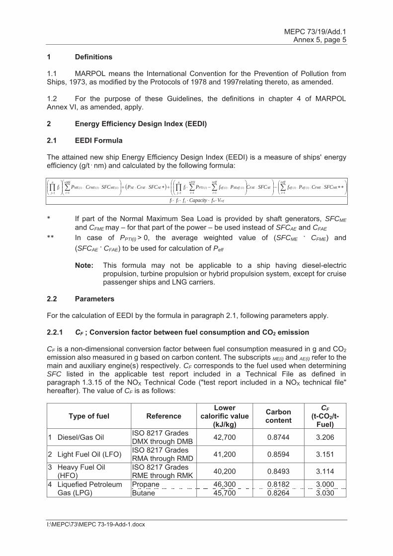
1 Definitions 1.1 MARPOL means the International Convention for the Prevention of Pollution from Ships, 1973, as modified by the Protocols of 1978 and 1997relating thereto, as amended. 1.2 For the purpose of these Guidelines, the definitions in chapter 4 of MARPOL Annex VI, as amended, apply. 2 Energy Efficiency Design Index (EEDI) 2.1 EEDI Formula The attained new ship Energy Efficiency Design Index (EEDI) is a measure of ships' energy efficiency (g/t . nm) and calculated by the following formula:
* If part of the Normal Maximum Sea Load is provided by shaft generators, SFCME and CFME may – for that part of the power – be used instead of SFCAE and CFAE
** In case of PPTI(i) > 0, the average weighted value of (SFCME . CFME) and (SFCAE . CFAE) to be used for calculation of Peff Note: This formula may not be applicable to a ship having diesel-electric
propulsion, turbine propulsion or hybrid propulsion system, except for cruise passenger ships and LNG carriers.
2.2 Parameters For the calculation of EEDI by the formula in paragraph 2.1, following parameters apply. 2.2.1 CF ; Conversion factor between fuel consumption and CO2 emission CF is a non-dimensional conversion factor between fuel consumption measured in g and CO2 emission also measured in g based on carbon content. The subscripts ME(i) and AE(i) refer to the main and auxiliary engine(s) respectively. CF corresponds to the fuel used when determining SFC listed in the applicable test report included in a Technical File as defined in paragraph 1.3.15 of the NOX Technical Code ("test report included in a NOX technical file" hereafter). The value of CF is as follows:
Type of fuel Reference Lower
calorific value (kJ/kg)
Carbon content
CF (t-CO2/t-
Fuel) 1 Diesel/Gas Oil ISO 8217 Grades
DMX through DMB 42,700 0.8744 3.206
2 Light Fuel Oil (LFO) ISO 8217 Grades RMA through RMD 41,200 0.8594 3.151
3 Heavy Fuel Oil (HFO)
ISO 8217 Grades RME through RMK 40,200 0.8493 3.114
4 Liquefied Petroleum Gas (LPG)
Propane 46,300 0.8182 3.000 Butane 45,700 0.8264 3.030
refwlci
neff
iMEFMEieffieffAEFAE
nPTI
i
neff
iiAEeffieffiPTI
n
j
jAEFAEAEiMEiFME
nME
iiME
n
j
j
VfCapacityfff
SFCCPfSFCCPfPfSFCCPSFCCPf1
)()(1 1
)()()(
1
)()(1
)(
1
MEPC 73/19/Add.1 Annex 5, page 6
I:\MEPC\73\MEPC 73-19-Add-1.docx
5 Liquefied Natural Gas (LNG) 48,000 0.7500 2.750
6 Methanol 19,900 0.3750 1.375 7 Ethanol 26,800 0.5217 1.913 In case of a ship equipped with a dual-fuel main or auxiliary engine, the CF-factor for gas fuel and the CF-factor for fuel oil should apply and be multiplied with the specific fuel oil consumption of each fuel at the relevant EEDI load point. Meanwhile, gas fuel should be identified whether it is regarded as the "primary fuel" in accordance with the formula below:
fDFgas =
gasgasgasgasiliquidiliquidiliquidiliquid
nLiquid
i
gasgasgasgasngasfuel
iigasfuel
ntotal
iitotal
KLCVVKLCVV
KLCVV
P
P
)()()()(11
)(
1)(
fDFliquid = 1- fDFgas where, fDFgas is the fuel availability ratio of gas fuel corrected for the power ratio of gas engines to total engines, fDFgas should not be greater than 1; Vgas is the total net gas fuel capacity on board in m3. If other arrangements, like exchangeable (specialized) LNG tank-containers and/or arrangements allowing frequent gas refuelling are used, the capacity of the whole LNG fuelling system should be used for Vgas . The boil-off rate (BOR) of gas cargo tanks can be calculated and included to Vgas if it is connected to the fuel gas supply system (FGSS); Vliquid is the total net liquid fuel capacity on board in m3 of liquid fuel tanks permanently connected to the ship's fuel system. If one fuel tank is disconnected by permanent sealing valves, Vliquid of the fuel tank can be ignored;
gas is the density of gas fuel in kg/m3;
liquid is the density of each liquid fuel in kg/m3; LCVgas is the low calorific value of gas fuel in kJ/kg; LCVliquid is the low calorific value of liquid fuel in kJ/kg; K gas is the filling rate for gas fuel tanks; Kliquid is the filling rate for liquid fuel tanks; Ptotal is the total installed engine power, PME and PAE in kW; Pgasfuel is the dual fuel engine installed power, PME and PAE in kW;
.1 If the total gas fuel capacity is at least 50% of the fuel capacity dedicated to the dual fuel engines , namely fDFgas ≥ 0.5, then gas fuel is regarded as the "Primary fuel," and fDFgas = 1 and fDFliquid = 0 for each dual fuel engine.
MEPC 73/19/Add.1 Annex 5, page 7
I:\MEPC\73\MEPC 73-19-Add-1.docx
.2 If fDFgas < 0.5, gas fuel is not regarded as the "primary fuel." The CF and SFC in the EEDI calculation for each dual fuel engine (both main and auxiliary engines) should be calculated as the weighted average of CF and SFC for liquid and gas mode, according to fDFgas and fDFliquid, such as the original item of PME(i)·CFME(i) ·SFCME(i) in the EEDI calculation is to be replaced by the formula below. PME(i)·(fDFgas(i)·(CFME pilot fuel(i) ·SFCME pilot fuel(i) + CFME gas(i) ·SFCME gas(i)) + fDFliquid(i)·CFME liquid(i) ·SFCME liquid(i))
2.2.2 Vref ; Ship speed Vref is the ship speed, measured in nautical miles per hour (knot), on deep water in the condition corresponding to the capacity as defined in paragraphs 2.2.3.1 and 2.2.3.3 (in case of passenger ships and cruise passenger ships, this condition should be summer load draught as provided in paragraph 2.2.4) at the shaft power of the engine(s) as defined in paragraph 2.2.5 and assuming the weather is calm with no wind and no waves. 2.2.3 Capacity Capacity is defined as follows. 2.2.3.1 For bulk carriers, tankers, gas carriers, LNG carriers, ro-ro cargo ships (vehicle
carriers), ro-ro cargo ships, ro-ro passenger ships, general cargo ships, refrigerated cargo carrier and combination carriers, deadweight should be used as capacity.
2.2.3.2 For passenger ships and cruise passenger ships, gross tonnage in accordance with
the International Convention of Tonnage Measurement of Ships 1969, annex I, regulation 3, should be used as capacity.
2.2.3.3 For containerships, 70% of the deadweight (DWT) should be used as capacity. EEDI
values for containerships are calculated as follows: .1 attained EEDI is calculated in accordance with the EEDI formula using 70%
deadweight for capacity. .2 estimated index value in the Guidelines for calculation of the reference line is
calculated using 70% deadweight as:
.3 parameters a and c for containerships in table 2 of regulation 21 of MARPOL
Annex VI are determined by plotting the estimated index value against 100% deadweight i.e. a = 174.22 and c=0.201 were determined.
.4 required EEDI for a new containership is calculated using 100% deadweight
as:
Required EEDI = (1-X/100) · a · 100% deadweight –c
where X is the reduction factor (in percentage) in accordance with table 1 in regulation 21 of MARPOL Annex VI relating to the applicable phase and size of new containership.
ref
NME
iAEiME
V
PPValueIndexEstimated
DWT%70
2151901144.3 1
MEPC 73/19/Add.1 Annex 5, page 8
I:\MEPC\73\MEPC 73-19-Add-1.docx
2.2.4 Deadweight Deadweight means the difference in tonnes between the displacement of a ship in water of relative density of 1,025 kg/m3 at the summer load draught and the lightweight of the ship. The summer load draught should be taken as the maximum summer draught as certified in the stability booklet approved by the Administration or an organization recognized by it. 2.2.5 P ; Power of main and auxiliary engines P is the power of the main and auxiliary engines, measured in kW. The subscripts ME(i) and AE(i) refer to the main and auxiliary engine(s), respectively. The summation on i is for all engines with the number of engines (nME) (see diagram in appendix 1). 2.2.5.1 PME(i) ; Power of main engines PME(i) is 75% of the rated installed power (MCR1) for each main engine (i). For LNG carriers having diesel electric propulsion system, PME(i) should be calculated by the following formula:
Where: MPPMotor(i) is the rated output of motor specified in the certified document.
(i) is to be taken as the product of electrical efficiency of generator, transformer, converter and motor, taking into consideration the weighted average as necessary. The electrical efficiency, (i), should be taken as 91.3% for the purpose of calculating attained EEDI. Alternatively, if the value more than 91.3% is to be applied, the (i) should be obtained by measurement and verified by method approved by the verifier. For LNG carriers having steam turbine propulsion systems, PME(i) is 83% of the rated installed power (MCRSteamTurbine) for each steam turbine(i). The influence of additional shaft power take off or shaft power take in is defined in the following paragraphs. 2.2.5.2 PPTO(i) ; Shaft generator In case where shaft generator(s) are installed, PPTO(i) is 75% of the rated electrical output power of each shaft generator. In case that shaft generator(s) are installed to steam turbine, PPTO(i) is 83% of the rated electrical output power and the factor of 0.75 should be replaced to 0.83. For calculation of the effect of shaft generators two options are available:
1 The value of MCR specified on the EIAPP certificate should be used for calculation. If the main engines are
not required to have an EIAPP certificate, the MCR on the nameplate should be used.
)(
)()( 83.0
i
iMotoriME
MPPP
MEPC 73/19/Add.1 Annex 5, page 9
I:\MEPC\73\MEPC 73-19-Add-1.docx
Option 1: The maximum allowable deduction for the calculation of PME(i) is to be no more than PAE as defined in paragraph 2.2.5.6. For this case, PME(i) is calculated as:
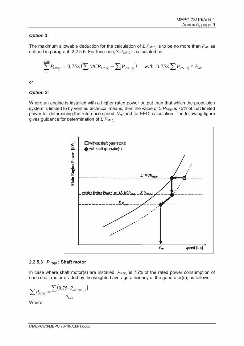
or Option 2: Where an engine is installed with a higher rated power output than that which the propulsion system is limited to by verified technical means, then the value of PME(i) is 75% of that limited power for determining the reference speed, Vref and for EEDI calculation. The following figure gives guidance for determination of PME(i):
2.2.5.3 PPTI(i) ; Shaft motor
In case where shaft motor(s) are installed, PPTI(i) is 75% of the rated power consumption of each shaft motor divided by the weighted average efficiency of the generator(s), as follows:
Where:
AEiPTOiPTOiME
nME
iiME PPwithPMCRP 75.0 75.0 )()(
1)(
Mai
n En
gine
Pow
er [
kW]
speed [kn]
verified limited Power or ( MCRME(i) – PPTO(i) )
without shaft generator(s)with shaft generator(s)
MCRME(i)
PME(i)
vref
Mai
n En
gine
Pow
er [
kW]
speed [kn]
verified limited Power or ( MCRME(i) – PPTO(i) )
without shaft generator(s)with shaft generator(s)
MCRME(i)
PME(i)
vref
Gen
iSMiPTI
PP )max(,
)(
75.0
MEPC 73/19/Add.1 Annex 5, page 10
I:\MEPC\73\MEPC 73-19-Add-1.docx
is the rated power consumption of each shaft motor
is the weighted average efficiency of the generator(s) In case that shaft motor(s) are installed to steam turbine, PPTI(i) is 83% of the rated power consumption and the factor of 0.75 should be replaced to 0.83. The propulsion power at which Vref is measured, is:
Where:
is the efficiency of each shaft motor installed Where the total propulsion power as defined above is higher than 75% of the power the propulsion system is limited to by verified technical means, then 75% of the limited power is to be used as the total propulsion power for determining the reference speed, Vref and for EEDI calculation. In case of combined PTI/PTO, the normal operational mode at sea will determine which of these to be used in the calculation. Note: The shaft motor's chain efficiency may be taken into consideration to account for the
energy losses in the equipment from the switchboard to the shaft motor, if the chain efficiency of the shaft motor is given in a verified document.
2.2.5.4 Peff(i) ; Innovative mechanical energy efficient technology for main engine Peff(i) is the output of the innovative mechanical energy efficient technology for propulsion at 75% main engine power. Mechanical recovered waste energy directly coupled to shafts need not be measured, since the effect of the technology is directly reflected in the Vref. In case of a ship equipped with a number of engines, the CF and SFC should be the power weighted average of all the main engines. In case of a ship equipped with dual-fuel engine(s), the CF and SFC should be calculated in accordance with paragraphs 2.2.1 and 2.2.7. 2.2.5.5 PAEeff ; Innovative mechanical energy efficient technology for auxiliary engine PAEeff (i) is the auxiliary power reduction due to innovative electrical energy efficient technology measured at PME(i). 2.2.5.6 PAE ; Auxiliary engine power PAE is the required auxiliary engine power to supply normal maximum sea load including necessary power for propulsion machinery/systems and accommodation, e.g. main engine pumps, navigational systems and equipment and living on board, but excluding the power not for propulsion machinery/systems, e.g. thrusters, cargo pumps, cargo gear, ballast pumps, maintaining cargo, e.g. reefers and cargo hold fans, in the condition where the ship engaged in voyage at the speed (Vref) under the condition as mentioned in paragraph 2.2.2.
)max(, iSMP
Gen
ShaftiPTIiME PP ),()(
)()max(,),( 75.0 iPTIiSMShaftiPTI PP
)(iPTI
MEPC 73/19/Add.1 Annex 5, page 11
I:\MEPC\73\MEPC 73-19-Add-1.docx
2.2.5.6.1 For ships which total propulsion power ( ) is 10,000 kW or
above, PAE is defined as:
2.2.5.6.2 For ships which total propulsion power ( ) is below
10,000 kW, PAE is defined as:
2.2.5.6.3 For LNG carriers with a reliquiefaction system or compressor(s), designed to be
used in normal operation and essential to maintain the LNG cargo tank pressure below the maximum allowable relief valve setting of a cargo tank in normal operation, the following terms should be added to above PAE formula in accordance with 2.2.5.6.3.1, 2.2.5.6.3.2 or 2.2.5.6.3.3 as below: .1 For ships having re-liquefaction system:
Where:
CargoTankCapacityLNG is the LNG Cargo Tank Capacity in m3. BOR is the design rate of boil-off gas of entire ship per day, which is specified in the specification of the building contract.
COPreliquefy is the coefficient of design power performance for reliquefying boil-off gas per unit volume, as follows:
COPcooling is the coefficient of design performance of reliquefaction and 0.166 should be used. Another value calculated by the manufacturer and verified by the Administration or an organization recognized by the Administration may be used.
)(iMEMCR75.0
)(iPTIP
25075.0
025.0 1)(
)(1
000,10)(
nPTI
iiPTI
iME
nME
iAE
PMCRP
kWiMEMCR
)(iMEMCR75.0
)(iPTIP
75.005.0 1
)(
)(1
000,10)(
nPTI
iiPTI
iME
nME
iAE
PMCRP
kWiMEMCR
reliquefyreliquefyLNG RCOPBORapacityCargoTankC
coolingreliquefy COPh
kgkJmkgCOP(sec)3600)(24
)/(511)/(425 3
MEPC 73/19/Add.1 Annex 5, page 12
I:\MEPC\73\MEPC 73-19-Add-1.docx
Rreliquefy is the ratio of boil-off gas (BOG) to be re-liquefied to entire BOG, calculated as follows:
.2 For LNG carriers with direct diesel driven propulsion system or diesel electric
propulsion system, having compressor(s) which are used for supplying high-pressured gas derived from boil-off gas to the installed engines (typically intended for 2-stroke dual fuel engines):
Where:
COPcomp is the design power performance of compressor and 0.33 (kWh/kg) should be used. Another value calculated by the manufacturer and verified by the Administration or an organization recognized by the Administration may be used.
.3 For LNG carriers with direct diesel driven propulsion system or diesel electric
propulsion system, having compressor(s) which are used for supplying low-pressured gas derived from boil-off gas to the installed engines (typically intended for 4-stroke dual fuel engines):
2
2.2.5.6.4 For LNG carriers having diesel electric propulsion system, MPPMotor(i) should be
used instead MCRME(i) for PAE calculation. 2.2.5.6.5 For LNG carriers having steam turbine propulsion system and of which electric
power is primarily supplied by turbine generator closely integrated into the steam and feed water systems, PAE may be treated as 0(zero) instead of taking into account electric load in calculating SFCSteamTurbine.
2.2.5.7 Use of electric power table For ship where the PAE value calculated by paragraphs 2.2.5.6.1 to 2.2.5.6.3 is significantly different from the total power used at normal seagoing, e.g. in cases of passenger ships (see NOTE under the formula of EEDI), the PAE value should be estimated by the consumed electric power (excluding propulsion) in conditions when the ship is engaged in a voyage at reference speed (Vref) as given in the electric power table,3 divided by the average efficiency of the generator(s) weighted by power (see appendix 2). 2 With regard to the factor of 0.02, it is assumed that the additional energy needed to compress BOG for
supplying to a 4-stroke dual fuel engine is approximately equal to 2% of PME, compared to the energy needed to compress BOG for supplying to a steam turbine.
3 The electric power table should be examined and validated by the verifier. Where ambient conditions affect
any electrical load in the power table, such as that for heating ventilation and air conditioning systems, the contractual ambient conditions leading to the maximum design electrical load of the installed system for the ship in general should apply.
total
reliquefyreliquefy BOG
BOGR
nME
i
iMEgasmodeiMEcomp
PSFCCOP
1
)(),( 1000
nME
iiMEP
1)(02.0
MEPC 73/19/Add.1 Annex 5, page 13
I:\MEPC\73\MEPC 73-19-Add-1.docx
2.2.6 Consistency of parameters Vref, Capacity and P Vref, Capacity and P should be consistent with each other. As for LNG carries having diesel electric or steam turbine propulsion systems, Vref is the relevant speed at 83% of MPPMotor or MCRSteamTubine respectively. 2.2.7 SFC; Certified specific fuel consumption SFC is the certified specific fuel consumption, measured in g/kWh, of the engines or steam turbines. 2.2.7.1 SFC for main and auxiliary engines The subscripts ME(i) and AE(i) refer to the main and auxiliary engine(s), respectively. For engines certified to the E2 or E3 test cycles of the NOX Technical Code 2008, the engine Specific Fuel Consumption (SFCME(i)) is that recorded in the test report included in a NOX technical file for the engine(s) at 75% of MCR power of its torque rating. For engines certified to the D2 or C1 test cycles of the NOX Technical Code 2008, the engine Specific Fuel Consumption (SFCAE(i)) is that recorded on the test report included in a NOX technical file at the engine(s) 50% of MCR power or torque rating. If gas fuel is used as primary fuel in accordance with paragraph 4.2.3 of the Guidelines on survey and certification of the energy efficiency design index (EEDI), SFC in gas mode should be used. In case that installed engine(s) have no approved NOX Technical File tested in gas mode, the SFC of gas mode should be submitted by the manufacturer and confirmed by the verifier. The SFC should be corrected to the value corresponding to the ISO standard reference conditions using the standard lower calorific value of the fuel oil (42,700kJ/kg), referring to ISO 15550:2002 and ISO 3046-1:2002. For ships where the PAE value calculated by paragraphs 2.2.5.6.1 to 2.2.5.6.3 is significantly different from the total power used at normal seagoing, e.g. conventional passenger ships, the Specific Fuel Consumption (SFCAE) of the auxiliary generators is that recorded in the test report included in a NOX technical file for the engine(s) at 75% of MCR power of its torque rating. SFCAE is the power-weighted average among SFCAE(i) of the respective engines i. For those engines which do not have a test report included in a NOX technical file because its power is below 130 kW, the SFC specified by the manufacturer and endorsed by a competent authority should be used. At the design stage, in case of unavailability of test report in the NOX file, the SFC specified by the manufacturer and endorsed by a competent authority should be used. For LNG driven engines of which SFC is measured in kJ/kWh should be corrected to the SFC value of g/kWh using the standard lower calorific value of the LNG (48,000 kJ/kg), referring to the 2006 IPCC Guidelines. Reference lower calorific values of additional fuels are given in the table in paragraph 2.2.1 of these Guidelines. The reference lower calorific value corresponding to the conversion factor of the respective fuel should be used for calculation.
MEPC 73/19/Add.1 Annex 5, page 14
I:\MEPC\73\MEPC 73-19-Add-1.docx
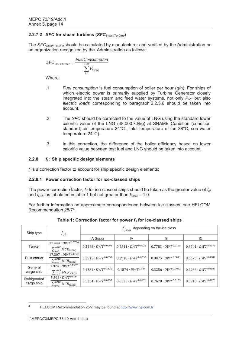
2.2.7.2 SFC for steam turbines (SFCSteamTurbine) The SFCSteamTurbine should be calculated by manufacturer and verified by the Administration or an organization recognized by the Administration as follows:
Where:
.1 Fuel consumption is fuel consumption of boiler per hour (g/h). For ships of which electric power is primarily supplied by Turbine Generator closely integrated into the steam and feed water systems, not only PME but also electric loads corresponding to paragraph 2.2.5.6 should be taken into account.
.2 The SFC should be corrected to the value of LNG using the standard lower
calorific value of the LNG (48,000 kJ/kg) at SNAME Condition (condition standard; air temperature 24°C , inlet temperature of fan 38°C, sea water temperature 24°C).
.3 In this correction, the difference of the boiler efficiency based on lower
calorific value between test fuel and LNG should be taken into account. 2.2.8 fj ; Ship specific design elements fj is a correction factor to account for ship specific design elements: 2.2.8.1 Power correction factor for ice-classed ships The power correction factor, fj, for ice-classed ships should be taken as the greater value of fj0 and fj,min as tabulated in table 1 but not greater than fj,max = 1.0. For further information on approximate correspondence between ice classes, see HELCOM Recommendation 25/74.
Table 1: Correction factor for power f j for ice-classed ships
Ship type depending on the ice class
IA Super IA IB IC
Tanker
Bulk carrier
General cargo ship
Refrigerated cargo ship
4 HELCOM Recommendation 25/7 may be found at http://www.helcom.fi
nME
iiME
neSteamTurbi
P
ptionFuelConsumSFC
1)(
MEPC 73/19/Add.1 Annex 5, page 15
I:\MEPC\73\MEPC 73-19-Add-1.docx
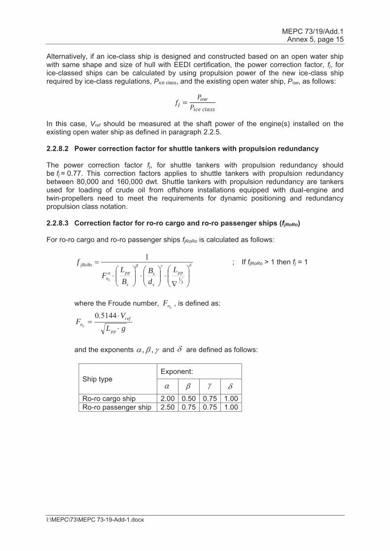
Alternatively, if an ice-class ship is designed and constructed based on an open water ship with same shape and size of hull with EEDI certification, the power correction factor, fj, for ice-classed ships can be calculated by using propulsion power of the new ice-class ship required by ice-class regulations, Pice class, and the existing open water ship, Pow, as follows:
In this case, Vref should be measured at the shaft power of the engine(s) installed on the existing open water ship as defined in paragraph 2.2.5. 2.2.8.2 Power correction factor for shuttle tankers with propulsion redundancy The power correction factor fj, for shuttle tankers with propulsion redundancy should be fj = 0.77. This correction factors applies to shuttle tankers with propulsion redundancy between 80,000 and 160,000 dwt. Shuttle tankers with propulsion redundancy are tankers used for loading of crude oil from offshore installations equipped with dual-engine and twin-propellers need to meet the requirements for dynamic positioning and redundancy propulsion class notation. 2.2.8.3 Correction factor for ro-ro cargo and ro-ro passenger ships (fjRoRo) For ro-ro cargo and ro-ro passenger ships fjRoRo is calculated as follows:
; If fjRoRo > 1 then fj = 1
where the Froude number, , is defined as:
and the exponents and are defined as follows:
Ship type Exponent:
Ro-ro cargo ship 2.00 0.50 0.75 1.00 Ro-ro passenger ship 2.50 0.75 0.75 1.00
31
1
pp
s
s
s
ppn
jRoRoL
dB
BL
F
f
L
LnF
gLV
Fpp
refnL
5144.0
,,
MEPC 73/19/Add.1 Annex 5, page 16
I:\MEPC\73\MEPC 73-19-Add-1.docx
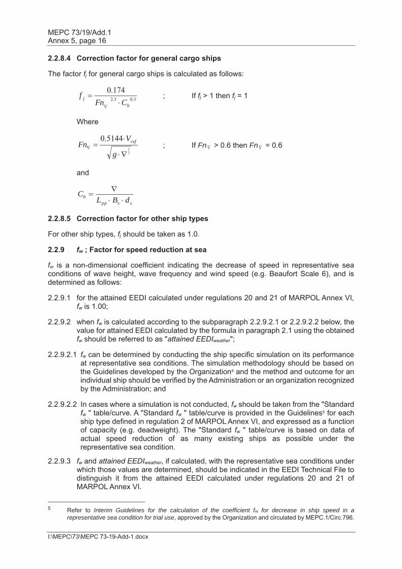
2.2.8.4 Correction factor for general cargo ships The factor fj for general cargo ships is calculated as follows:
; If fj > 1 then fj = 1
Where
; If Fn > 0.6 then Fn = 0.6
and
2.2.8.5 Correction factor for other ship types For other ship types, fj should be taken as 1.0. 2.2.9 fw ; Factor for speed reduction at sea fw is a non-dimensional coefficient indicating the decrease of speed in representative sea conditions of wave height, wave frequency and wind speed (e.g. Beaufort Scale 6), and is determined as follows: 2.2.9.1 for the attained EEDI calculated under regulations 20 and 21 of MARPOL Annex VI,
fw is 1.00; 2.2.9.2 when fw is calculated according to the subparagraph 2.2.9.2.1 or 2.2.9.2.2 below, the
value for attained EEDI calculated by the formula in paragraph 2.1 using the obtained fw should be referred to as "attained EEDIweather";
2.2.9.2.1 fw can be determined by conducting the ship specific simulation on its performance
at representative sea conditions. The simulation methodology should be based on the Guidelines developed by the Organization4 and the method and outcome for an individual ship should be verified by the Administration or an organization recognized by the Administration; and
2.2.9.2.2 In cases where a simulation is not conducted, fw should be taken from the "Standard
fw " table/curve. A "Standard fw " table/curve is provided in the Guidelines5 for each ship type defined in regulation 2 of MARPOL Annex VI, and expressed as a function of capacity (e.g. deadweight). The "Standard fw " table/curve is based on data of actual speed reduction of as many existing ships as possible under the representative sea condition.
2.2.9.3 fw and attained EEDIweather, if calculated, with the representative sea conditions under
which those values are determined, should be indicated in the EEDI Technical File to distinguish it from the attained EEDI calculated under regulations 20 and 21 of MARPOL Annex VI.
5 Refer to Interim Guidelines for the calculation of the coefficient fw for decrease in ship speed in a
representative sea condition for trial use, approved by the Organization and circulated by MEPC.1/Circ.796.
3.03.2
174.0
bj CFn
f
31
5144.0
g
VFn ref
ssppb dBL
C

MEPC 73/19/Add.1 Annex 5, page 17
I:\MEPC\73\MEPC 73-19-Add-1.docx
2.2.10 feff(i) ; Factor of each innovative energy efficiency technology feff(i) is the availability factor of each innovative energy efficiency technology. feff(i) for waste energy recovery system should be one (1.0)6. 2.2.11 fi ; Capacity factor for technical/regulatory limitation on capacity fi is the capacity factor for any technical/regulatory limitation on capacity, and should be assumed to be one (1.0) if no necessity of the factor is granted. 2.2.11.1 Capacity correction factor for ice-classed ships The capacity correction factor, fi, for ice-classed ships having DWT as the measure of capacity should be calculated as follows:
, where is the capacity correction factor for ice-strengthening of the ship, which can be obtained from Table 2 and is the capacity correction factor for improved ice-going capability, which should not be less than 1.0 and which should be calculated as follows:
, where is the average block coefficient for the ship type, which can be obtained from Table 3 for bulk carriers, tankers and general cargo ships, and is the block coefficient of the ship. For ship types other than bulk carriers, tankers and general cargo ships,
6 EEDI calculation should be based on the normal seagoing condition outside Emission Control Area
designated under regulation 13.6 of MARPOL ANNEX VI.

MEPC 73/19/Add.1 Annex 5, page 18
I:\MEPC\73\MEPC 73-19-Add-1.docx
Table 2: Capacity correction factor for ice-strengthening of the hull
Ice class7
IC fi(IC) = 1.0041 + 58.5/DWT
IB fi(IB) = 1.0067 + 62.7/DWT
IA fi(IA) = 1.0099 + 95.1/DWT
IA Super fi(IAS) = 1.0151 + 228.7/DWT
Table 3: Average block coefficients Cb reference design for bulk carriers, tankers and general cargo ships
Size categories
Ship type below
10,000 DWT 10,000 –
25,000 DWT 25,000 –
55,000 DWT 55,000 –
75,000 DWT above
75,000 DWT
Bulk carrier 0.78 0.80 0.82 0.86 0.86
Tanker 0.78 0.78 0.80 0.83 0.83
General cargo ship 0.80
Alternatively, the capacity correction factor for ice-strengthening of the ship ( ) can be calculated by using the formula given for the ship specific voluntary enhancement correction coefficient ( ) in paragraph 2.2.11.2. This formula can also be used for other ice classes than those given in Table 2. 2.2.11.2 fi VSE
8 ; Ship specific voluntary structural enhancement
fi VSE for ship specific voluntary structural enhancement is expressed by the following formula:
where:
For this calculation the same displacement (Δ) for reference and enhanced design should be taken. DWT before enhancements (DWTreference design) is the deadweight prior to application of the structural enhancements. DWT after enhancements (DWTenhanced design) is the deadweight following the application of voluntary structural enhancement. A change of material (e.g. from 7 For further information on approximate correspondence between ice classes, see HELCOM
Recommendation 25/7, which can be found at http://www.helcom.fi
8 Structural and/or additional class notations such as, but not limited to, "strengthened for discharge with grabs" and "strengthened bottom for loading/unloading aground", which result in a loss of deadweight of the ship, are also seen as examples of "voluntary structural enhancements".
designenhanced
designreferenceVSEi DWT
DWTf
designreferenceshipdesignreference tlightweighDWT
designenhancedshipdesignenhanced tlightweighDWT
MEPC 73/19/Add.1 Annex 5, page 19
I:\MEPC\73\MEPC 73-19-Add-1.docx
aluminum alloy to steel) between reference design and enhanced design should not be allowed for the fi VSE calculation. A change in grade of the same material (e.g. in steel type, grades, properties and condition) should also not be allowed.
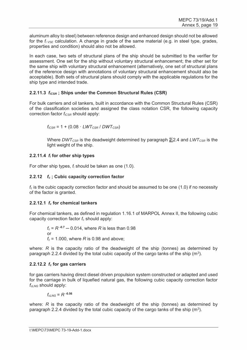
In each case, two sets of structural plans of the ship should be submitted to the verifier for assessment. One set for the ship without voluntary structural enhancement; the other set for the same ship with voluntary structural enhancement (alternatively, one set of structural plans of the reference design with annotations of voluntary structural enhancement should also be acceptable). Both sets of structural plans should comply with the applicable regulations for the ship type and intended trade. 2.2.11.3 fiCSR ; Ships under the Common Structural Rules (CSR) For bulk carriers and oil tankers, built in accordance with the Common Structural Rules (CSR) of the classification societies and assigned the class notation CSR, the following capacity correction factor fiCSR should apply: fiCSR = 1 + (0.08 · LWTCSR / DWTCSR) Where DWTCSR is the deadweight determined by paragraph 2.2.4 and LWTCSR is the
light weight of the ship. 2.2.11.4 fi for other ship types For other ship types, fi should be taken as one (1.0). 2.2.12 fc ; Cubic capacity correction factor fc is the cubic capacity correction factor and should be assumed to be one (1.0) if no necessity of the factor is granted. 2.2.12.1 fc for chemical tankers For chemical tankers, as defined in regulation 1.16.1 of MARPOL Annex II, the following cubic capacity correction factor fc should apply:
fc = R -0.7 ─ 0.014, where R is less than 0.98 or fc = 1.000, where R is 0.98 and above;
where: R is the capacity ratio of the deadweight of the ship (tonnes) as determined by paragraph 2.2.4 divided by the total cubic capacity of the cargo tanks of the ship (m3). 2.2.12.2 fc for gas carriers for gas carriers having direct diesel driven propulsion system constructed or adapted and used for the carriage in bulk of liquefied natural gas, the following cubic capacity correction factor fcLNG should apply:
fcLNG = R -0.56 where: R is the capacity ratio of the deadweight of the ship (tonnes) as determined by paragraph 2.2.4 divided by the total cubic capacity of the cargo tanks of the ship (m3).
MEPC 73/19/Add.1 Annex 5, page 20
I:\MEPC\73\MEPC 73-19-Add-1.docx
Note: This factor is applicable to LNG carriers defined as gas carriers in regulation 2.26 of MARPOL Annex VI and should not be applied to LNG carriers defined in regulation 2.38 of MARPOL Annex VI.
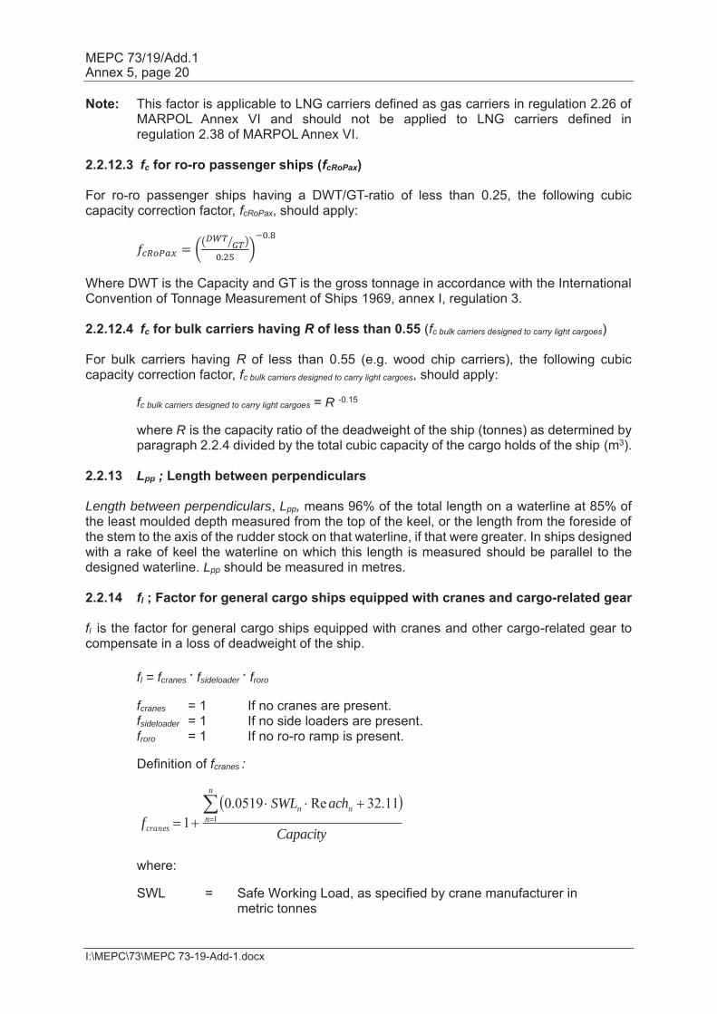
2.2.12.3 fc for ro-ro passenger ships (fcRoPax) For ro-ro passenger ships having a DWT/GT-ratio of less than 0.25, the following cubic capacity correction factor, fcRoPax, should apply:
Where DWT is the Capacity and GT is the gross tonnage in accordance with the International Convention of Tonnage Measurement of Ships 1969, annex I, regulation 3. 2.2.12.4 fc for bulk carriers having R of less than 0.55 (fc bulk carriers designed to carry light cargoes) For bulk carriers having R of less than 0.55 (e.g. wood chip carriers), the following cubic capacity correction factor, fc bulk carriers designed to carry light cargoes, should apply:
fc bulk carriers designed to carry light cargoes = R -0.15
where R is the capacity ratio of the deadweight of the ship (tonnes) as determined by paragraph 2.2.4 divided by the total cubic capacity of the cargo holds of the ship (m3).
2.2.13 Lpp ; Length between perpendiculars Length between perpendiculars, Lpp, means 96% of the total length on a waterline at 85% of the least moulded depth measured from the top of the keel, or the length from the foreside of the stem to the axis of the rudder stock on that waterline, if that were greater. In ships designed with a rake of keel the waterline on which this length is measured should be parallel to the designed waterline. Lpp should be measured in metres. 2.2.14 fl ; Factor for general cargo ships equipped with cranes and cargo-related gear fl is the factor for general cargo ships equipped with cranes and other cargo-related gear to compensate in a loss of deadweight of the ship. fl = fcranes . fsideloader . froro fcranes = 1 If no cranes are present. fsideloader = 1 If no side loaders are present. froro = 1 If no ro-ro ramp is present. Definition of fcranes :
where:
SWL = Safe Working Load, as specified by crane manufacturer in metric tonnes
Capacity
achSWLf
n
nnn
cranes1
11.32Re0519.01
MEPC 73/19/Add.1 Annex 5, page 21
I:\MEPC\73\MEPC 73-19-Add-1.docx
Reach = Reach at which the Safe Working Load can be applied in metres N = Number of cranes For other cargo gear such as side loaders and ro-ro ramps, the factor should be defined as follows:
The weight of the side loaders and ro-ro ramps should be based on a direct calculation, in analogy to the calculations as made for factor fivse.
2.2.15 ds ; Summer load line draught Summer load line draught, ds is the vertical distance, in metres, from the moulded baseline at mid-length to the waterline corresponding to the summer freeboard draught to be assigned to the ship. 2.2.16 Bs ; Breadth Breadth, Bs, is the greatest moulded breadth of the ship, in metres, at or below the load line draught, ds. 2.2.17 Volumetric displacement Volumetric displacement, , in cubic metres (m3), is the volume of the moulded displacement of the ship, excluding appendages, in a ship with a metal shell, and is the volume of displacement to the outer surface of the hull in a ship with a shell of any other material, both taken at the summer load line draught, ds, as stated in the approved stability booklet/loading manual. 2.2.18 g ; Gravitational acceleration g is the gravitational acceleration, 9.81m/s2.
ssideloader
ssideloaderNosideloader Capacity
Capacityf
RoRo
RoRoNoRoRo Capacity
Capacityf
MEPC 73/19/Add.1 Annex 5, page 22
I:\MEPC\73\MEPC 73-19-Add-1.docx
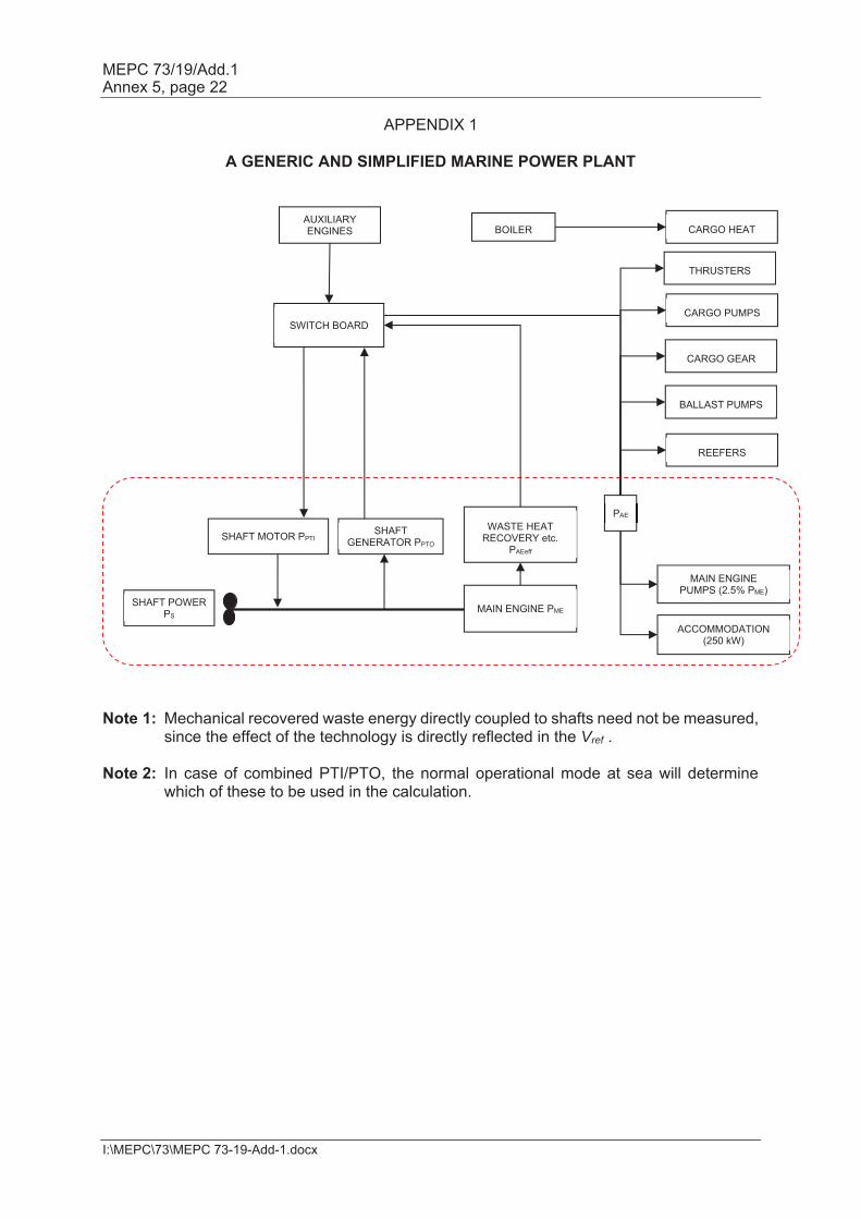
APPENDIX 1
A GENERIC AND SIMPLIFIED MARINE POWER PLANT
Note 1: Mechanical recovered waste energy directly coupled to shafts need not be measured,
since the effect of the technology is directly reflected in the Vref . Note 2: In case of combined PTI/PTO, the normal operational mode at sea will determine
which of these to be used in the calculation.
AUXILIARY ENGINES
BOILER
CARGO HEAT
THRUSTERS
CARGO PUMPS
REEFERS
CARGO GEAR
BALLAST PUMPS
SWITCH BOARD
SHAFT MOTOR PPTI
WASTE HEAT RECOVERY etc.
PAEeff
MAIN ENGINE PME SHAFT POWER PS
MAIN ENGINE PUMPS (2.5% PME)
ACCOMMODATION (250 kW)
PAE
SHAFT GENERATOR PPTO
MEPC 73/19/Add.1 Annex 5, page 23
I:\MEPC\73\MEPC 73-19-Add-1.docx
APPENDIX 2
GUIDELINES FOR THE DEVELOPMENT OF ELECTRIC POWER TABLES FOR EEDI (EPT-EEDI)
1 Introduction This appendix contains a guideline for the document "Electric power table for EEDI" which is similar to the actual shipyards' load balance document, utilizing well defined criteria, providing standard format, clear loads definition and grouping, standard load factors, etc. A number of new definitions (in particular the "groups") are introduced, giving an apparent greater complexity to the calculation process. However, this intermediate step to the final calculation of PAE stimulates all the parties to a deep investigation through the global figure of the auxiliary load, allowing comparisons between different ships and technologies and eventually identifying potential efficiencies improvements. 2 Auxiliary load power definition PAE is to be calculated as indicated in paragraph 2.2.5.6 of the Guidelines, together with the following additional three conditions:
.1 non-emergency situations (e.g. "no fire", "no flood", "no blackout", "no partial blackout");
.2 evaluation time frame of 24 hours (to account loads with intermittent use);
and .3 ship fully loaded with passengers and/or cargo and crew.
3 Definition of the data to be included in the electric power table for EEDI The electric power table for EEDI calculation should contain the following data elements, as appropriate:
.1 Load's group;
.2 Load's description;
.3 Load's identification tag;
.4 Load's electric circuit Identification;
.5 Load's mechanical rated power "Pm" (kW);
.6 Load's electric motor rated output power (kW);
.7 Load's electric motor efficiency "e" (/);
.8 Load's Rated electric power "Pr" (kW);
.9 Service factor of load "kl" (/);
.10 Service factor of duty "kd" (/);
.11 Service factor of time "kt" (/);
.12 Service total factor of use "ku" (/), where ku=kl·kd·kt;
.13 Load's necessary power "Pload" (kW), where Pload=Pr·ku;
.14 Notes;
.15 Group's necessary power (kW); and
.16 Auxiliaries load's power PAE (kW).

MEPC 73/19/Add.1 Annex 5, page 24
I:\MEPC\73\MEPC 73-19-Add-1.docx
4 Data to be included in the electric power table for EEDI Load groups 4.1 The loads are divided into defined groups, allowing a proper breakdown of the auxiliaries. This eases the verification process and makes it possible to identify those areas where load reductions might be possible. The groups are listed below:
.1 A Hull, deck, navigation and safety services;
.2 B Propulsion service auxiliaries;
.3 C Auxiliary engine and main engine services;
.4 D Ship's general services;
.5 E Ventilation for engine-rooms and auxiliaries room;
.6 F Air conditioning services;
.7 G Galleys, refrigeration and laundries services;
.8 H Accommodation services;
.9 I Lighting and socket services;
.10 L Entertainment services;
.11 N Cargo loads; and
.12 M Miscellaneous. All the ship's loads should be delineated in the document, excluding only PAEeff, the shaft motors and shaft motors chain (while the propulsion services auxiliaries are partially included below in paragraph 4.1.2 B). Some loads (i.e. thrusters, cargo pumps, cargo gear, ballast pumps, maintaining cargo, reefers and cargo hold fans) still are included in the group for sake of transparency, however their service factor is zero in order to comply with paragraph 2.2.5.6 of the Guidelines (see rows 4 and 5 of the electric power table contained in this appendix), therefore making it easier to verify that all the loads have been considered in the document and there are no loads left out of the measurement. 4.1.1 A Hull, deck, navigation and safety services
.1 loads included in the hull services typically are: ICCP systems, mooring equipment, various doors, ballasting systems, bilge systems, stabilizing equipment, etc. Ballasting systems are indicated with service factor equal to zero to comply with paragraph 2.5.6 of the Guidelines (see row 5 of the electric power table contained in this appendix);
.2 loads included in the deck services typically are: deck and balcony washing
systems, rescue systems, cranes, etc.; .3 loads included in the navigation services typically are: navigation systems,
navigation's external and internal communication systems, steering systems, etc.; and
.4 loads included in the safety services typically are: active and passive fire
systems, emergency shutdown systems, public address systems, etc. 4.1.2 B Propulsion service auxiliaries This group typically includes: propulsion secondary cooling systems such as LT cooling pumps dedicated to shaft motors, LT cooling pumps dedicated to propulsion converters, propulsion UPSs, etc. Propulsion service loads do not include shaft motors (PTI(i)) and the auxiliaries
MEPC 73/19/Add.1 Annex 5, page 25
I:\MEPC\73\MEPC 73-19-Add-1.docx
which are part of them (shaft motor own cooling fans and pump, etc.) and the shaft motor chain losses and auxiliaries which are part of them (i.e. shaft motor converters including relevant auxiliaries such as converter own cooling fans and pumps, shaft motor transformers including relevant auxiliaries losses such as propulsion transformer own cooling fans and pumps, shaft motor harmonic filter including relevant auxiliaries losses, shaft motor excitation system including the relevant auxiliaries consumed power, etc.). Propulsion service auxiliaries include manoeuvring propulsion equipment such as manoeuvring thrusters and their auxiliaries whose service factor is to be set to zero. 4.1.3 C – Auxiliary engine and main engine services This group includes: cooling systems, i.e. pumps and fans for cooling circuits dedicated to alternators or propulsion shaft engines (seawater, technical water dedicated pumps, etc.), lubricating and fuel systems feeding, transfer, treatment and storage, ventilation system for combustion air supply, etc. 4.1.4 D – Ship's general services This group includes loads which provide general services which can be shared between shaft motor, auxiliary engines and main engine and accommodation support systems. Loads typically included in this group are: cooling systems, i.e. pumping seawater, technical water main circuits, compressed air systems, fresh water generators, automation systems, etc. 4.1.5 E Ventilation for engine-rooms and auxiliaries room This group includes all fans providing ventilation for engine-rooms and auxiliary rooms that typically are: engine-rooms cooling supply-exhaust fans, auxiliary rooms supply and exhaust fans. All the fans serving accommodation areas or supplying combustion air are not included in this group. This group does not include cargo hold fans and garage supply and exhaust fans. 4.1.6 F Air conditioning services All loads that make up the air conditioning service that typically are: air conditioning chillers, air conditioning cooling and heating fluids transfer and treatment, air conditioning's air handling units ventilation, air conditioning re-heating systems with associated pumping, etc. The air conditioning chillers service factor of load, service factor of time and service factor of duty are to be set as 1 (kl=1, kt=1 and kd=1) in order to avoid the detailed validation of the heat load dissipation document (i.e. the chiller's electric motor rated power is to be used). However, kd is to represent the use of spare chillers (e.g. four chillers are installed and one out four is spare then kd=0 for the spare chiller and kd=1 for the remaining three chillers), but only when the number of spare chillers is clearly demonstrated via the heat load dissipation document. 4.1.7 G Galleys, refrigeration and laundries services All loads related to the galleys, pantries refrigeration and laundry services that typically are: galleys various machines, cooking appliances, galleys' cleaning machines, galleys auxiliaries, refrigerated room systems including refrigeration compressors with auxiliaries, air coolers, etc. 4.1.8 H Accommodation services All loads related to the accommodation services of passengers and crew that typically are: crew and passengers' transportation systems, i.e. lifts, escalators, etc. environmental services, i.e. black and grey water collecting, transfer, treatment, storage, discharge, waste systems including collecting, transfer, treatment, storage, etc. accommodation fluids transfers, i.e. sanitary hot and cold water pumping, etc., treatment units, pools systems, saunas, gym equipment, etc.
MEPC 73/19/Add.1 Annex 5, page 26
I:\MEPC\73\MEPC 73-19-Add-1.docx
4.1.9 I Lighting and socket services All loads related to the lighting, entertainment and socket services. As the quantity of lighting circuits and sockets within the ship may be significantly high, it is not practically feasible to list all the lighting circuits and points in the EPT for EEDI. Therefore circuits should be grouped into subgroups aimed to identify possible improvements of efficient use of power. The subgroups are:
.1 Lighting for 1) cabins, 2) corridors, 3) technical rooms/stairs, 4) public spaces/stairs, 5) engine-rooms and auxiliaries' room, 6) external areas, 7) garages and 8) cargo spaces. All should be divided by main vertical zones; and
.2 Power sockets for 1) cabins, 2) corridors, 3) technical rooms/stairs, 4) public
spaces/stairs, 5) engine-rooms and auxiliaries' room, 6) garages and 7) cargo spaces. All should be divided by main vertical zones.
The calculation criteria for complex groups (e.g. cabin lighting and power sockets) subgroups are to be included via an explanatory note, indicating the load composition (e.g. lights of typical cabins, TV, hair dryer, fridge, etc., typical cabins). 4.1.10 L – Entertainment services This group includes all loads related to entertainment services, typically: public spaces audio and video equipment, theatre stage equipment, IT systems for offices, video games, etc. 4.1.11 N – Cargo loads This group will contain all cargo loads such as cargo pumps, cargo gear, maintaining cargo, cargo reefers loads, cargo hold fans and garage fans for sake of transparency. However, the service factor of this group is to be set to zero. 4.1.12 M – Miscellaneous This group will contain all loads which have not been associated to the above-mentioned groups but still are contributing to the overall load calculation of the normal maximum sea load. Loads description 4.2 This identifies the loads (for example "seawater pump"). Loads identification tag 4.3 This tag identifies the loads according to the shipyard's standards tagging system. For example, the "PTI1 fresh water pump" identification tag is "SYYIA/C" for an example ship and shipyard. This data provides a unique identifier for each load. Loads electric circuit Identification 4.4 This is the tag of the electric circuit supplying the load. Such information allows the data validation process.
MEPC 73/19/Add.1 Annex 5, page 27
I:\MEPC\73\MEPC 73-19-Add-1.docx
Loads mechanical rated power "Pm" 4.5 This data is to be indicated in the document only when th electric load is made by an electric motor driving a mechanical load (for example a fan, a pump, etc.). This is the rated power of the mechanical device driven by an electric motor. Loads electric motor rated output power (kW) 4.6 The output power of the electric motor as per maker's name plate or technical specification. This data does not take part of the calculation but is useful to highlight potential over rating of the combination motor-mechanical load. Loads electric motor efficiency "e" (/) 4.7 This data is to be entered in the document only when the electric load is made by an electric motor driving a mechanical load. Loads rated electric power "Pr" (kW) 4.8 Typically the maximum electric power absorbed at the load electric terminals at which the load has been designed for its service, as indicated on the maker's name plate and/or maker's technical specification. When the electric load is made by an electric motor driving a mechanical load the load's rated electric power is: Pr=Pm/e (kW). Service factor of load "kl" (/) 4.9 Provides the reduction from the loads rated electric power to loads necessary electric power that is to be made when the load absorb less power than its rated power. For example, in case of electric motor driving a mechanical load, a fan could be designed with some power margin, leading to the fact that the fan rated mechanical power exceeds the power requested by the duct system it serves. Another example is when a pump rated power exceed the power needed for pumping in its delivery fluid circuit. Another example in case of electric self-regulating semi-conductors electric heating system is oversized and the rated power exceeds the power absorbed, according a factor kl. Service factor of duty "kd" (/) 4.10 Factor of duty is to be used when a function is provided by more than one load. As all loads are to be included in the EPT for EEDI, this factor provides a correct summation of the loads. For example when two pumps serve the same circuit and they run in duty/stand-by their Kd factor will be ½ and ½. When three compressors serves the same circuit and one runs in duty and two in stand-by, then kd is 1/3, 1/3 and 1/3. Service factor of time "kt" (/) 4.11 A factor of time based on the shipyard's evaluation about the load duty along 24 hours of ship's navigation as defined at paragraph 3. For example the Entertainment loads operate at their power for a limited period of time, 4 hours out 24 hours; as a consequence kt=4/24. For example, the seawater cooling pumps operate at their power all the time during the navigation at Vref. As a consequence kt=1.

MEPC 73/19/Add.1 Annex 5, page 28
I:\MEPC\73\MEPC 73-19-Add-1.docx
Service total factor of use "ku" (/) 4.12 The total factor of use that takes into consideration all the service factors: ku=kl·kd·kt. Loads necessary power "Pload" (kW) 4.13 The individual user contribution to the auxiliary load power is Pload=Pr·ku. Notes 4.14 A note, as free text, could be included in the document to provide explanations to the verifier. Groups necessary power (kW) 4.15 The summation of the "Loads necessary power" from group A to N. This is an intermediate step which is not strictly necessary for the calculation of PAE. However, it is useful to allow a quantitative analysis of the PAE, providing a standard breakdown for analysis and potential improvements of energy saving. Auxiliaries load's power PAE (kW) 4.16 Auxiliaries load's power PAE is the summation of the "Load's necessary power" of all the loads divided by the average efficiency of the generator(s) weighted by power.
PAE=ΣPload(i)/( average efficiency of the generator(s) weighted by power) Layout and organization of the data indicated in the electric power table for EEDI 5 The document "Electric power table for EEDI" is to include general information (i.e. ship's name, project name, document references, etc.) and a table with:
.1 one row containing column titles; .2 one Column for table row ID; .3 one Column for the groups identification ("A", "B", etc.) as indicated in
paragraphs 4.1.1 to 4.1.12 of this appendix; .4 one Column for the group descriptions as indicated in paragraphs 4.1.1
to 4.1.12 of this appendix; .5 one column each for items in paragraphs 4.2 to 4.14 of this appendix
(e.g. "load tag", etc.); .6 one row dedicated to each individual load; .7 the summation results (i.e. summation of powers) including data from
paragraphs 4.15 to 4.16 of this appendix; and .8 explanatory notes.
An example of an electric power table for EEDI for a cruise postal ship which transports passengers and has a car garage and reefer holds for fish trade transportation is indicated below. The data indicated and the type of ship is for reference only.

MEPC 73/19/Add.1 Annex 5, page 29
I:\MEPC\73\MEPC 73-19-Add-1.docx
MEPC 73/19/Add.1 Annex 5, page 30
I:\MEPC\73\MEPC 73-19-Add-1.docx
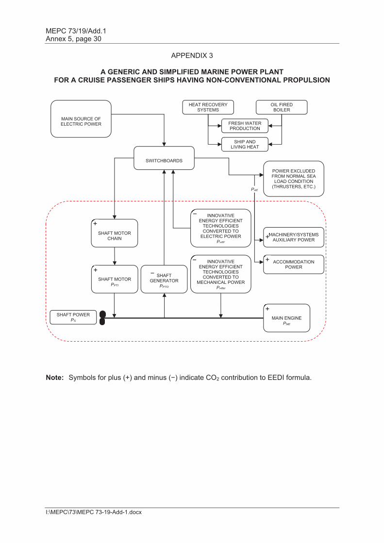
APPENDIX 3
A GENERIC AND SIMPLIFIED MARINE POWER PLANT FOR A CRUISE PASSENGER SHIPS HAVING NON-CONVENTIONAL PROPULSION
Note: Symbols for plus (+) and minus (−) indicate CO2 contribution to EEDI formula.
MAIN SOURCE OF ELECTRIC POWER
SHIP AND LIVING HEAT
SWITCHBOARDS
SHAFT MOTOR
PPTI
INNOVATIVE ENERGY EFFICIENT
TECHNOLOGIES CONVERTED TO
ELECTRIC POWER PeffE
MAIN ENGINE
PME
SHAFT POWER PS
ACCOMMODATION POWER
PAE
SHAFT GENERATOR
PPTO
SHAFT MOTOR
CHAIN
INNOVATIVE ENERGY EFFICIENT
TECHNOLOGIES CONVERTED TO
MECHANICAL POWER PeffM
MACHINERY/SYSTEMS AUXILIARY POWER
POWER EXCLUDED FROM NORMAL SEA
LOAD CONDITION (THRUSTERS, ETC.)
FRESH WATER PRODUCTION
HEAT RECOVERY SYSTEMS
OIL FIRED BOILER
M+
−
+
+
+
+ −
−
MEPC 73/19/Add.1 Annex 5, page 31
I:\MEPC\73\MEPC 73-19-Add-1.docx
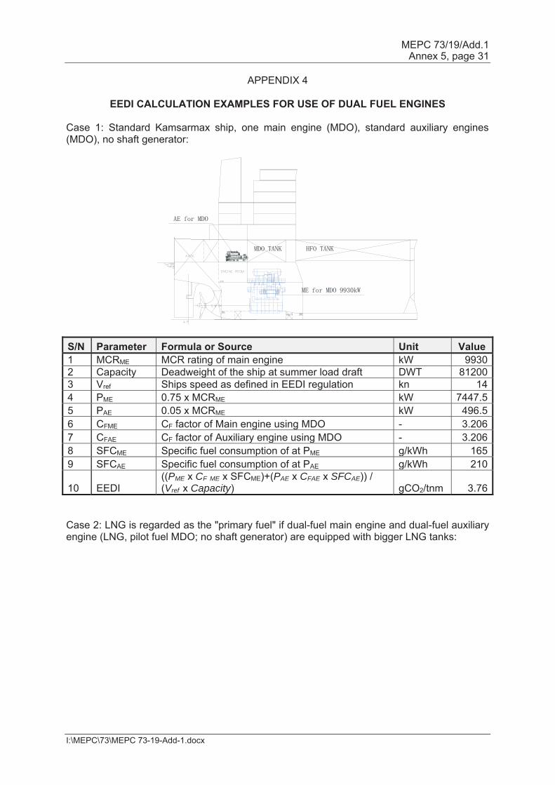
APPENDIX 4
EEDI CALCULATION EXAMPLES FOR USE OF DUAL FUEL ENGINES Case 1: Standard Kamsarmax ship, one main engine (MDO), standard auxiliary engines (MDO), no shaft generator:
S/N Parameter Formula or Source Unit Value 1 MCRME MCR rating of main engine kW 9930 2 Capacity Deadweight of the ship at summer load draft DWT 81200 3 Vref Ships speed as defined in EEDI regulation kn 14 4 PME 0.75 x MCRME kW 7447.5 5 PAE 0.05 x MCRME kW 496.5 6 CFME CF factor of Main engine using MDO - 3.206 7 CFAE CF factor of Auxiliary engine using MDO - 3.206 8 SFCME Specific fuel consumption of at PME g/kWh 165 9 SFCAE Specific fuel consumption of at PAE g/kWh 210
10 EEDI ((PME x CF ME x SFCME)+(PAE x CFAE x SFCAE)) / (Vref x Capacity) gCO2/tnm 3.76
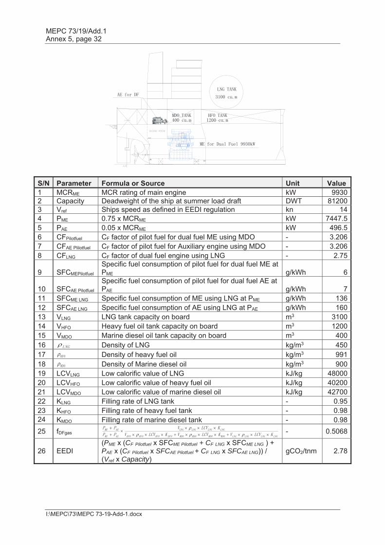
Case 2: LNG is regarded as the "primary fuel" if dual-fuel main engine and dual-fuel auxiliary engine (LNG, pilot fuel MDO; no shaft generator) are equipped with bigger LNG tanks:
MEPC 73/19/Add.1 Annex 5, page 32
I:\MEPC\73\MEPC 73-19-Add-1.docx
S/N Parameter Formula or Source Unit Value 1 MCRME MCR rating of main engine kW 9930 2 Capacity Deadweight of the ship at summer load draft DWT 81200 3 Vref Ships speed as defined in EEDI regulation kn 14 4 PME 0.75 x MCRME kW 7447.5 5 PAE 0.05 x MCRME kW 496.5 6 CFPilotfuel CF factor of pilot fuel for dual fuel ME using MDO - 3.206 7 CFAE Plilotfuel CF factor of pilot fuel for Auxiliary engine using MDO - 3.206 8 CFLNG CF factor of dual fuel engine using LNG - 2.75
9 SFCMEPilotfuel Specific fuel consumption of pilot fuel for dual fuel ME at PME g/kWh 6
10 SFCAE Pilotfuel Specific fuel consumption of pilot fuel for dual fuel AE at PAE g/kWh 7
11 SFCME LNG Specific fuel consumption of ME using LNG at PME g/kWh 136 12 SFCAE LNG Specific fuel consumption of AE using LNG at PAE g/kWh 160 13 VLNG LNG tank capacity on board m3 3100 14 VHFO Heavy fuel oil tank capacity on board m3 1200 15 VMDO Marine diesel oil tank capacity on board m3 400 16 Density of LNG kg/m3 450 17 Density of heavy fuel oil kg/m3 991 18 Density of Marine diesel oil kg/m3 900 19 LCVLNG Low calorific value of LNG kJ/kg 48000 20 LCVHFO Low calorific value of heavy fuel oil kJ/kg 40200 21 LCVMDO Low calorific value of marine diesel oil kJ/kg 42700 22 KLNG Filling rate of LNG tank - 0.95 23 KHFO Filling rate of heavy fuel tank - 0.98 24 KMDO Filling rate of marine diesel tank - 0.98 25 fDFgas
- 0.5068
26 EEDI (PME x (CF Pilotfuel x SFCME Pilotfuel + CF LNG x SFCME LNG ) + PAE x (CF Pilotfuel x SFCAE Pilotfuel + CF LNG x SFCAE LNG)) / (Vref x Capacity)
gCO2/tnm 2.78
MEPC 73/19/Add.1 Annex 5, page 33
I:\MEPC\73\MEPC 73-19-Add-1.docx
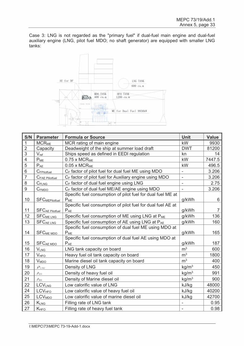
Case 3: LNG is not regarded as the "primary fuel" if dual-fuel main engine and dual-fuel auxiliary engine (LNG, pilot fuel MDO; no shaft generator) are equipped with smaller LNG tanks:
S/N Parameter Formula or Source Unit Value 1 MCRME MCR rating of main engine kW 9930 2 Capacity Deadweight of the ship at summer load draft DWT 81200 3 Vref Ships speed as defined in EEDI regulation kn 14 4 PME 0.75 x MCRME kW 7447.5 5 PAE 0.05 x MCRME kW 496.5 6 CFPilotfuel CF factor of pilot fuel for dual fuel ME using MDO - 3.206 7 CFAE Plilotfuel CF factor of pilot fuel for Auxiliary engine using MDO - 3.206 8 CFLNG CF factor of dual fuel engine using LNG - 2.75 9 CFMDO CF factor of dual fuel ME/AE engine using MDO - 3.206
10 SFCMEPilotfuel Specific fuel consumption of pilot fuel for dual fuel ME at PME g/kWh 6
11 SFCAE Pilotfuel Specific fuel consumption of pilot fuel for dual fuel AE at PAE g/kWh 7
12 SFCME LNG Specific fuel consumption of ME using LNG at PME g/kWh 136 13 SFCAE LNG Specific fuel consumption of AE using LNG at PAE g/kWh 160
14 SFCME MDO Specific fuel consumption of dual fuel ME using MDO at PME g/kWh 165
15 SFCAE MDO Specific fuel consumption of dual fuel AE using MDO at PAE g/kWh 187
16 VLNG LNG tank capacity on board m3 600 17 VHFO Heavy fuel oil tank capacity on board m3 1800 18 VMDO Marine diesel oil tank capacity on board m3 400 19 Density of LNG kg/m3 450 20 Density of heavy fuel oil kg/m3 991 21 Density of Marine diesel oil kg/m3 900 22 LCVLNG Low calorific value of LNG kJ/kg 48000 24 LCVHFO Low calorific value of heavy fuel oil kJ/kg 40200 25 LCVMDO Low calorific value of marine diesel oil kJ/kg 42700 26 KLNG Filling rate of LNG tank - 0.95 27 KHFO Filling rate of heavy fuel tank - 0.98

MEPC 73/19/Add.1 Annex 5, page 34
I:\MEPC\73\MEPC 73-19-Add-1.docx
S/N Parameter Formula or Source Unit Value 28 KMDO Filling rate of marine diesel tank - 0.98 29 fDFgas
- 0.1261
30 fDFliquid 1- fDFgas - 0.8739
31 EEDI
(PME x (fDFgas x (CF Pilotfuel x SFCME Pilotfuel + CF LNG x SFCME LNG ) + fDFliquid x CFMDO x SFCME MDO) + PAE x (fDFgas x (CFAE Pilotfuel x SFCAE Pilotfuel + CF LNG x SFCAE LNG)+ fDFliquid x CFMDO x SFCAE MDO)) / (Vref x Capacity)
gCO2/tnm 3.61
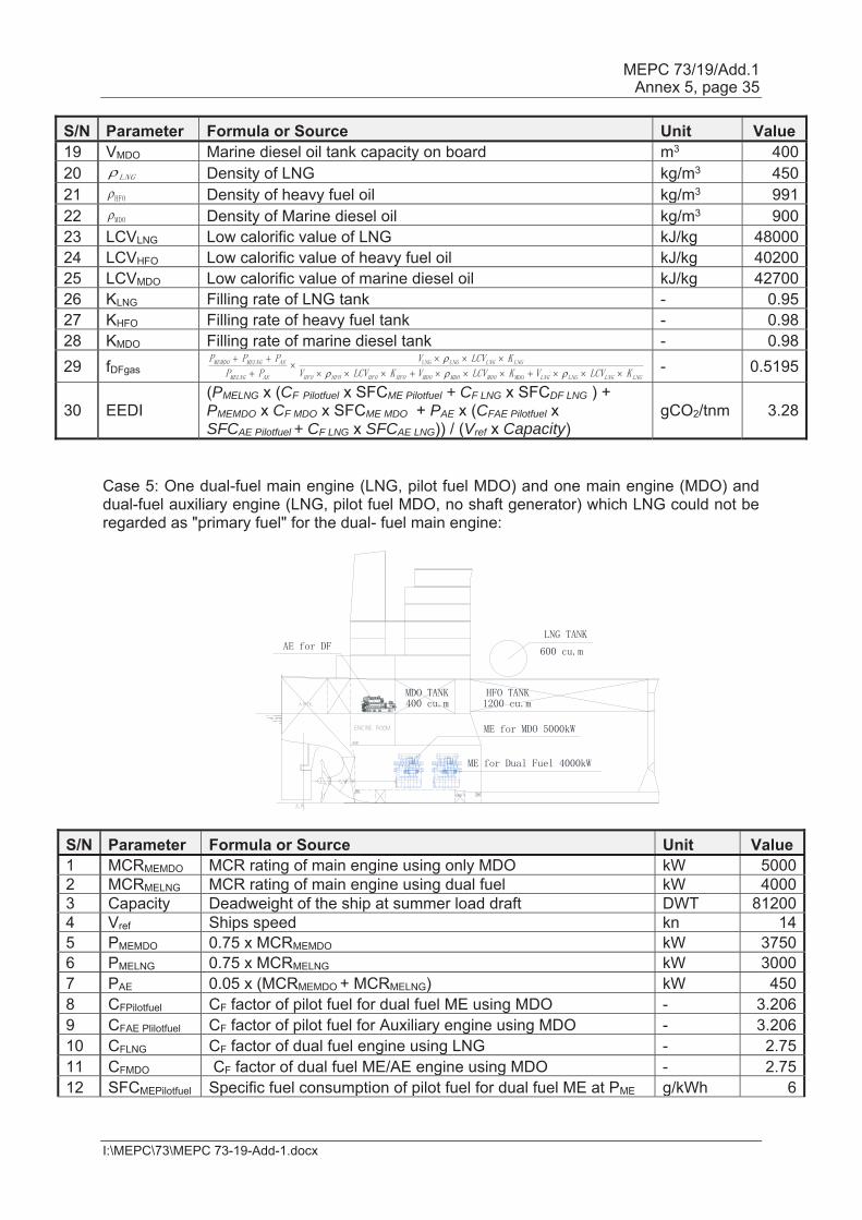
Case 4: One dual-fuel main engine (LNG, pilot fuel MDO) and one main engine (MDO) and dual-fuel auxiliary engine (LNG, pilot fuel MDO, no shaft generator) which LNG could be regarded as "primary fuel" only for the dual-fuel main engine:
S/N Parameter Formula or Source Unit Value 1 MCRMEMDO MCR rating of main engine using only MDO kW 5000 2 MCRMELNG MCR rating of main engine using dual fuel kW 4000 3 Capacity Deadweight of the ship at summer load draft DWT 81200 4 Vref Ships speed kn 14 5 PMEMDO 0.75 x MCRMEMDO kW 3750 6 PMELNG 0.75 x MCRMELNG kW 3000 7 PAE 0.05 x (MCRMEMDO + MCRMELNG) kW 450 8 CFPilotfuel CF factor of pilot fuel for dual fuel ME using MDO - 3.206 9 CFAE Plilotfuel CF factor of pilot fuel for Auxiliary engine using MDO - 3.206 10 CFLNG CF factor of dual fuel engine using LNG - 2.75 11 CFMDO CF factor of dual fuel ME/AE engine using MDO - 3.206 12 SFCMEPilotfuel Specific fuel consumption of pilot fuel for dual fuel ME at PME g/kWh 6 13 SFCAE Pilotfuel Specific fuel consumption of pilot fuel for dual fuel AE at PAE g/kWh 7 14 SFCDF LNG Specific fuel consumption of dual fuel ME using LNG at PME g/kWh 158 15 SFCAE LNG Specific fuel consumption of AE using LNG at PAE g/kWh 160 16 SFCME MDO Specific fuel consumption of single fuel ME at PME g/kWh 180 17 VLNG LNG tank capacity on board m3 1000 18 VHFO Heavy fuel oil tank capacity on board m3 1200
MEPC 73/19/Add.1 Annex 5, page 35
I:\MEPC\73\MEPC 73-19-Add-1.docx
S/N Parameter Formula or Source Unit Value 19 VMDO Marine diesel oil tank capacity on board m3 400 20 Density of LNG kg/m3 450 21 Density of heavy fuel oil kg/m3 991 22 Density of Marine diesel oil kg/m3 900 23 LCVLNG Low calorific value of LNG kJ/kg 48000 24 LCVHFO Low calorific value of heavy fuel oil kJ/kg 40200 25 LCVMDO Low calorific value of marine diesel oil kJ/kg 42700 26 KLNG Filling rate of LNG tank - 0.95 27 KHFO Filling rate of heavy fuel tank - 0.98 28 KMDO Filling rate of marine diesel tank - 0.98 29 fDFgas
- 0.5195
30 EEDI (PMELNG x (CF Pilotfuel x SFCME Pilotfuel + CF LNG x SFCDF LNG ) + PMEMDO x CF MDO x SFCME MDO + PAE x (CFAE Pilotfuel x SFCAE Pilotfuel + CF LNG x SFCAE LNG)) / (Vref x Capacity)
gCO2/tnm 3.28
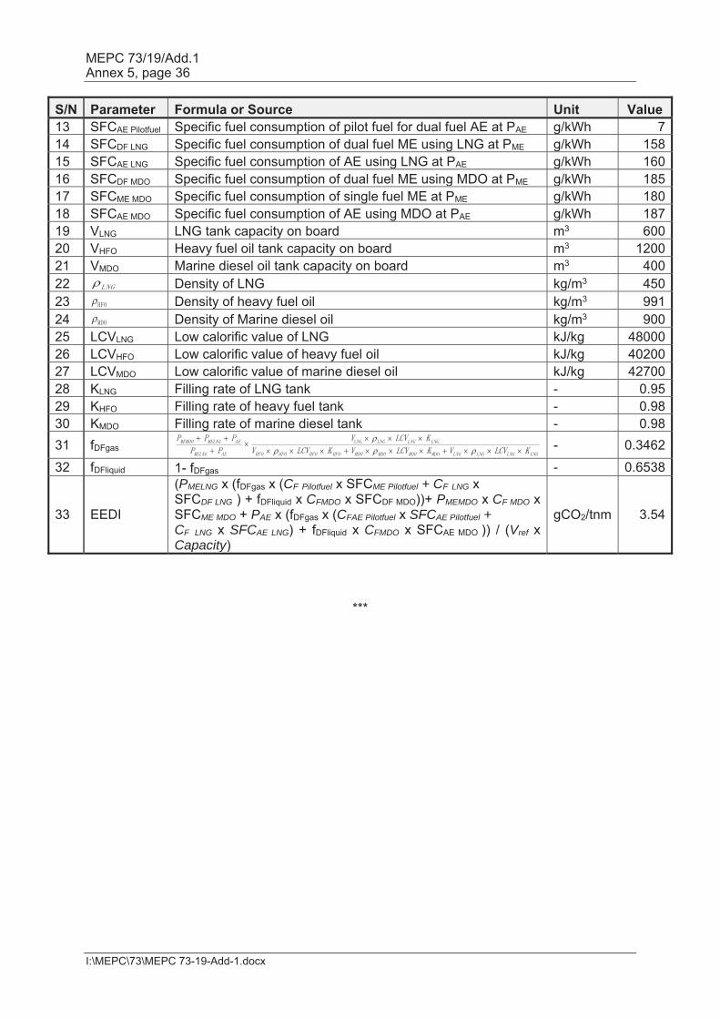
Case 5: One dual-fuel main engine (LNG, pilot fuel MDO) and one main engine (MDO) and dual-fuel auxiliary engine (LNG, pilot fuel MDO, no shaft generator) which LNG could not be regarded as "primary fuel" for the dual- fuel main engine:
S/N Parameter Formula or Source Unit Value 1 MCRMEMDO MCR rating of main engine using only MDO kW 5000 2 MCRMELNG MCR rating of main engine using dual fuel kW 4000 3 Capacity Deadweight of the ship at summer load draft DWT 81200 4 Vref Ships speed kn 14 5 PMEMDO 0.75 x MCRMEMDO kW 3750 6 PMELNG 0.75 x MCRMELNG kW 3000 7 PAE 0.05 x (MCRMEMDO + MCRMELNG) kW 450 8 CFPilotfuel CF factor of pilot fuel for dual fuel ME using MDO - 3.206 9 CFAE Plilotfuel CF factor of pilot fuel for Auxiliary engine using MDO - 3.206 10 CFLNG CF factor of dual fuel engine using LNG - 2.75 11 CFMDO CF factor of dual fuel ME/AE engine using MDO - 2.75 12 SFCMEPilotfuel Specific fuel consumption of pilot fuel for dual fuel ME at PME g/kWh 6
MEPC 73/19/Add.1 Annex 5, page 36
I:\MEPC\73\MEPC 73-19-Add-1.docx
S/N Parameter Formula or Source Unit Value 13 SFCAE Pilotfuel Specific fuel consumption of pilot fuel for dual fuel AE at PAE g/kWh 7 14 SFCDF LNG Specific fuel consumption of dual fuel ME using LNG at PME g/kWh 158 15 SFCAE LNG Specific fuel consumption of AE using LNG at PAE g/kWh 160 16 SFCDF MDO Specific fuel consumption of dual fuel ME using MDO at PME g/kWh 185 17 SFCME MDO Specific fuel consumption of single fuel ME at PME g/kWh 180 18 SFCAE MDO Specific fuel consumption of AE using MDO at PAE g/kWh 187 19 VLNG LNG tank capacity on board m3 600 20 VHFO Heavy fuel oil tank capacity on board m3 1200 21 VMDO Marine diesel oil tank capacity on board m3 400 22 Density of LNG kg/m3 450 23 Density of heavy fuel oil kg/m3 991 24 Density of Marine diesel oil kg/m3 900 25 LCVLNG Low calorific value of LNG kJ/kg 48000 26 LCVHFO Low calorific value of heavy fuel oil kJ/kg 40200 27 LCVMDO Low calorific value of marine diesel oil kJ/kg 42700 28 KLNG Filling rate of LNG tank - 0.95 29 KHFO Filling rate of heavy fuel tank - 0.98 30 KMDO Filling rate of marine diesel tank - 0.98 31 fDFgas
- 0.3462
32 fDFliquid 1- fDFgas - 0.6538
33 EEDI
(PMELNG x (fDFgas x (CF Pilotfuel x SFCME Pilotfuel + CF LNG x SFCDF LNG ) + fDFliquid x CFMDO x SFCDF MDO))+ PMEMDO x CF MDO x SFCME MDO + PAE x (fDFgas x (CFAE Pilotfuel x SFCAE Pilotfuel + CF LNG x SFCAE LNG) + fDFliquid x CFMDO x SFCAE MDO )) / (Vref x Capacity)
gCO2/tnm 3.54
***