Andrew ION M Installation
78
Aug.2008 1 PRIVATE AND CONFIDENTIAL © CommScope
-
Upload
timmylau23 -
Category
Documents
-
view
1.254 -
download
14
description
Andrew ION-M Installation Guide
Transcript of Andrew ION M Installation

Aug.2008 1PRIVATE AND CONFIDENTIAL© CommScope
������
������ �����
��������� �

Aug.2008 2PRIVATE AND CONFIDENTIAL© CommScope
���� ������ ����
� you will be able to install the ION-M master unit and remote unit
� you know details about the fibre connection and optical basic’s
� you will be able to commission an ION-M optical distribution system
� you will understand all parts of the ION-M master unit

Aug.2008 3PRIVATE AND CONFIDENTIAL© CommScope
� ����
� ION-M remote unit
� fibre connection and installing
� ION-M master unit (all parts, mini master)

Aug.2008 4PRIVATE AND CONFIDENTIAL© CommScope
� 1. Remote Unit
– Installation
– Connection
– Fibre connection
– special RU versions (UMTS - HP, single band)
� ������������� ������������ ����� �����
� ������������
� �����������
� ��������
� ���� ���������
� ���� �����������������������
������������ �������

Aug.2008 5PRIVATE AND CONFIDENTIAL© CommScope
���������������������
����������������
���������
�����������������������
�������!����
��������� ������ !�"!#�$�%����� ����&

Aug.2008 6PRIVATE AND CONFIDENTIAL© CommScope
'� �(������ ������ !�"!#�$
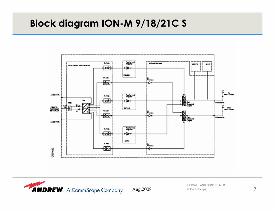
Aug.2008 7PRIVATE AND CONFIDENTIAL© CommScope
'� �(������ ������ !�"!#�$��

Aug.2008 8PRIVATE AND CONFIDENTIAL© CommScope
� The unit has to be mounted vertically, fans in top position.
� To ensure sufficient airflow a distance between wall andremote unit of at least 50mm has to be kept for each cabinet side. If this minimal distance of 50mm is reached at two of the cabinet sides, a distance of at least 200mm has to be observed for the remaining two sides. At top and bottom a minimal distance of 50mm has to be kept, as well.
� The unit may also be mounted on poles. Suitable pole mounting kits are available.
������)�� ��*��+�,���� �����

Aug.2008 9PRIVATE AND CONFIDENTIAL© CommScope
GSM NSO
Air inlet Air outlet
PSU
PSU
Distribution unit
(E)GSM duplexer
Optical module
Amplifiers
GSM1800/UMTS duplexer
��������� !�"!#��$�%�&�)�� ��*��

Aug.2008 10PRIVATE AND CONFIDENTIAL© CommScope
Fan housing
Air inlet
Air outlet
GSM NSO
PSU
Control board
(E)GSM duplexer
UMTS NSO
GSM1800/UMTS duplexer
Optical module
��������� !�"!#��$�%�&�)�� ��*��

Aug.2008 11PRIVATE AND CONFIDENTIAL© CommScope
1. Hang the backside heat sink parts into the screws of the mounting rack.
������� �����+�-������� ��������� �

Aug.2008 12PRIVATE AND CONFIDENTIAL© CommScope
2. Fit the pins at the back of the heat distribution unit(of the remote unit) into the bore holes provided inboth sides of the heat sink backside and fasten theunit with the 16 M5 Allen screws.
Heat distributionunit
Remoteunit
Heatdistributor
RU
������� �����+�-������� ��������� �

Aug.2008 13PRIVATE AND CONFIDENTIAL© CommScope
3. Tighten the six M8nuts to fasten the units tothe mounting rack. M8 nuts
M8 nuts
4. Install one half of the heat sinkfrontside by fitting the bore holes onits back into the pins on the heatdistribution unit.
5. Fasten this part with eight Allenscrews M5x16 (using e.g. a T-handled driver as illustrated below).
Heat distribution unit
Heat sinkfrontside,left half
Heat sinkbackside,right half
Heat distributor RU
"#$%&�$�� ���� ���'��������!� �������(
������� �����+�-������� ��������� �

Aug.2008 14PRIVATE AND CONFIDENTIAL© CommScope
�������- ���� ������-� ������
Nut M8 DIN 934
� ��������������������)�����������!������������������������������������*������������������������ ��������������
� ��������������)��������!�������+���������*���+���������������
� �������*�������������'������������������)���������������,���)���!��� �������������������������'��!�������������

Aug.2008 15PRIVATE AND CONFIDENTIAL© CommScope
� ����������+���*�������������-�����+��������������������+�����������������������������������������+�������*��������-��*������������������!���
� $��������������*������.����.���+�����+���*���������'����+��������)�����+������)��)����������*����.�����'�)������+�� �������.���+���������������/����������������������������)��������+����*������!������0�1231�)��������+������'�)�������0�1�4�"5�6���������*����+�����+���*���������'���
� 7���������*������.����.����������������*��������!��+�����������+���!����������.�������*������!���������+������������������������������'�)�������������)���+����������������� $��������'�)�������������)����������*����+�����+���*���������'�����������!�����������*���*�������������+�������
� ������ ��.��-� ��� �

Aug.2008 16PRIVATE AND CONFIDENTIAL© CommScope
� ������ ��.��-� ��� �

Aug.2008 17PRIVATE AND CONFIDENTIAL© CommScope
������� ��� �����������- ���� ������
-� ������
Aug.2008 18PRIVATE AND CONFIDENTIAL© CommScope
� ���������*������������������������!�+��������������*�)����**���������������!��� ���*�.��������������!��������������������������!���������!���
� �������������������������������������*�����������������.�.������������������������������������������������������!���������������������������/��������������������+��*����������������������*�����������������������)���������������������� ����������������������������������������������������*���������
� �+���������������������+�������������������������������������!��������*���������.�����������������������������!��*�.�����)����������������
/�������������� �

Aug.2008 19PRIVATE AND CONFIDENTIAL© CommScope
� 8�+���������������������������������������������������������������������������������������**�������������������
� ��'���������������**�*������������!��'����������.������ ��� ��������.�����������������!��)�������������������������
� ��������������+���������**��������*�)�����'����-���������*�)�����'������!�����!�����������������
/�������������� �

Aug.2008 20PRIVATE AND CONFIDENTIAL© CommScope
' � ���� ������ !�"!#�$

Aug.2008 21PRIVATE AND CONFIDENTIAL© CommScope
' � ���� ������ !�"!#�$��
Aug.2008 22PRIVATE AND CONFIDENTIAL© CommScope
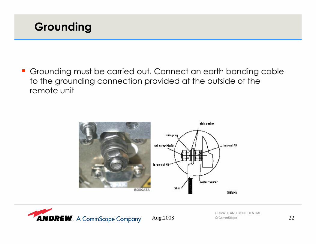
� 9�������������!�����������������������������!���������!���
���������������������������*�.���������������������+�����
�����������
0� ������

Aug.2008 23PRIVATE AND CONFIDENTIAL© CommScope
� AC-Connection
– Caution: make sure that AC is switched off before connecting or disconnecting
� Antennas are connected to the antenna terminal. Do not use tools to turn connector. Fasten it only by hand.
� Two connectors are provided for external alarms
$ ������� ��� �� ����� �1$�� ���

Aug.2008 24PRIVATE AND CONFIDENTIAL© CommScope
� In case options for AC supply are used the following wiring has to apply.
� The switch box has to be connected before the insulating transformer
,���������� � � �� �1$������������� ����

Aug.2008 25PRIVATE AND CONFIDENTIAL© CommScope
� :��������!��������*�����4;���*��+������+�������:��������� ������!���������������)�������+��������*��+�������+������
'� �(������� ������� !�"!#�$

Aug.2008 26PRIVATE AND CONFIDENTIAL© CommScope
���������� ������ !�"!#�$
� Output power in DL:
– GSM 900 MHz: + 24 dBm (up to 16 carr.); +30 dBm (up to 4 carr.)
– DCS 1800 MHz + 27 dBm (up to 16 carr.); +33 dBM (up to 4 carr.)
– UMTS 2100 MHz + 40 dBm (one carr.)
+ 37 dBm (two carr.)
+ 34 dBm (four carr.)
� Power consumption: max. 450 Watts (Triband)
� Antenna connection: N-type, male
� Mechanical size: 831x156x147 mm
� Weight: approx. 20 kg
� Cascading up to 4 ION-M9/18/21C using one fibre is possible (also using optical splitter in MU). Make sure that minimum optical wavelength difference from one RU to each other RU in this case is 0.4 nm (By choosing the correct optical interface module).

Aug.2008 27PRIVATE AND CONFIDENTIAL© CommScope
���������� ������#�-
� The MMR21P is intended for UMTS only. It offers high DL output power in the same size as standard MMR.
� Also available as MMR21PD with additional UL diversity path, that requires a second fibre.
� Output power in DL:
– UMTS 2100 MHz + 43 dBm (one carr.)
+ 40 dBm (two carr.)
+ 36 dBm (four carr.)
+ 32,5 dBm (eight carr.)
+ 30 dBm (12 carr.)
� Power consumption: max. 280 Watts
� max. opt. Loss to MU: 5 dB (recommended, 10 dB max.)
� Antenna connection: N-type, male
� Mechanical size: 831x156x147 mm
� Weight: approx. 20 kg

Aug.2008 28PRIVATE AND CONFIDENTIAL© CommScope
'� �(������ ��������#�-%2&

Aug.2008 29PRIVATE AND CONFIDENTIAL© CommScope
� Proper fibre installation is essential for reliable operation of the whole system.
� Clean fibres in case optical performance gets worse.
� Clean fibres only according to Andrew recommended cleaning procedure.
� Always disconnect units during splicing process, otherwise optical components may be damaged.
� The MMR-system is a WDM system. Optical loss in DL and UL might vary due to different optical wavelengths
� OTDR measurements have to be performed with both optical wavelenghts (1310 and 1550 nm) and in both directions
#��.����� ����� ������������

Aug.2008 30PRIVATE AND CONFIDENTIAL© CommScope
�������������
.���������� �

Aug.2008 31PRIVATE AND CONFIDENTIAL© CommScope
.���������� �
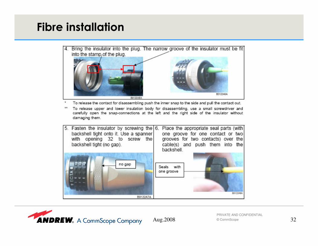
Aug.2008 32PRIVATE AND CONFIDENTIAL© CommScope
.���������� �

Aug.2008 33PRIVATE AND CONFIDENTIAL© CommScope
.���������� �

Aug.2008 34PRIVATE AND CONFIDENTIAL© CommScope
7������.����!��'��
� ��������������*���������+�������*������+�!��������������������*������!����**���������!�����*��������!��'����$��+������������!�����������+���������)���������*����� �+��������������������+�������������*����'��
.���������� �

Aug.2008 35PRIVATE AND CONFIDENTIAL© CommScope
3����������%����&
� $����������������+����!��)����������8���:������������������������7��)����7��+�������� ������������������� �+�)������

Aug.2008 36PRIVATE AND CONFIDENTIAL© CommScope
�����*���%�����&
4��������.��)��+���������!��'������������+����!���������#*������$�<�
� $����*�������������!���������������������������!�.������*�)����**������������+���������������#�������������=�������!������!��'*�.������*����+���*�����)���*�������������.��������������*������!���*������������!����� ����+�������!�����

Aug.2008 37PRIVATE AND CONFIDENTIAL© CommScope
�����*���%�����&
� Behind each optical transceiver the UL & DL band ports required for levelling the individual bands are located. Thus, the transceiver has to be removed for the levelling procedure.
� In case of multi-band / single-user systems, instead of combiners the subrack is equipped with BTS-connect units providing either one BTS connector for levelling or two separate connectors, one each for UL and DL.

Aug.2008 38PRIVATE AND CONFIDENTIAL© CommScope
�����*���%�����&
� For single-band or single-user systems a stand-alone subrack equipped with three OTRX plus BTS-connect units, and one power supply unit (PSU) is available. This subrack type provides additional space for a control unit to be upgraded as mini master unit .
� For single-band applications such a subrack is equipped with one combiner or BTS-connect unit per OTRX.
� For single-user setup this subrack can be equipped with the BTS-connect 3:3(one input per band) or the standard BTS-connect

Aug.2008 39PRIVATE AND CONFIDENTIAL© CommScope
�����*���%�--���� �&
� #*���������+��9��>11��9��5,11�������$����������!������ ���!���-��**���)���������77�+�������� ��*���*�)��*����������
� $����77�!������)�������������������*����+��������!����������������*�������� ������������*���*�)���+�������������+���������������
� �+�������*���*�)���2�����������������������!����+�)��� +����������������*�������+�)�����������������������������������+�56��8�)����!������+������*������*���������������� ��
� 4�*����������������2���� ����!���+�����������+�������!�����������*���*�)������������������!������������������!��.��������������*�)���*���+����+������������ � ��������.������!�����*���+����������������?��/��������@ �+�����������������

Aug.2008 40PRIVATE AND CONFIDENTIAL© CommScope
'� �(������ ���*

Aug.2008 41PRIVATE AND CONFIDENTIAL© CommScope
'� �(������� ���*�%�����&
Aug.2008 42PRIVATE AND CONFIDENTIAL© CommScope
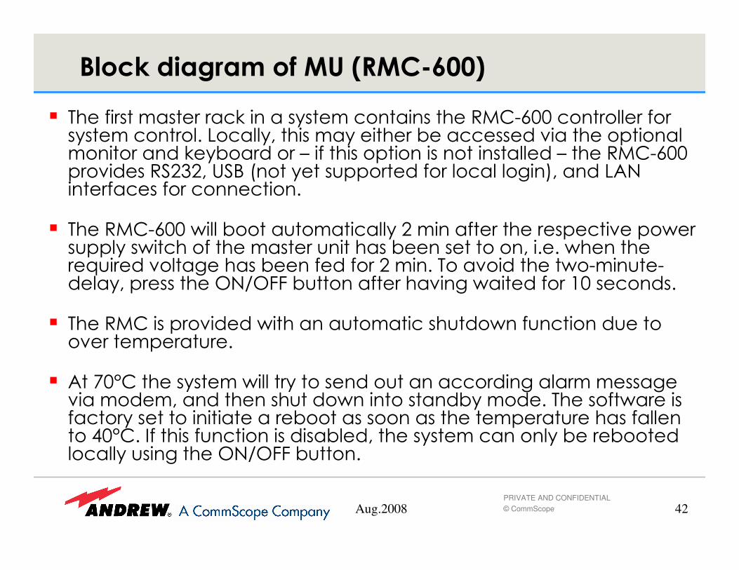
� $���+����� �������'������������ ������������������A11����������+�������� ���������;�������������� ���������!�����������.��������*������������������'��!������� �+�������*����������������������� ��������A11�*�.��������3����8� ����������**�����+��������������������;�"����+�����+�������������
� $�������A11�)����!��������������������� ����+���������*����.��*�)����**����)������+��������������������!��������������������)���������-�����.�����������!����+���+����� ����$���.���������)��� �������������*��������#"=#::�!�������+�����.����)������+��51���������
� $����������*�.�����)�����������������������)��+����������������.�����*�������
� ���B1C������������ �)����������������������������������� ���������.��������������������������)������������!��������$�����+�)�����+�������������������������!����������������������*����������+���������01C����+������+���������������!��������������� ����������!���!�����������������������#"=#::�!������
'� �(������� ���*�%)�$�455&

Aug.2008 43PRIVATE AND CONFIDENTIAL© CommScope
� $�������A11������*���������!���-��**���)������!������!��'�*�'��� 88�����'��*��*������� ��*���������������� ������� ���+�����������������+�*�)��+������
� $���!��������*�����"���D��5�� �
� �+�+�����������������!������!��'�*�������**��������� ��*�������+���**�2��5�6�������������������.����������������������$��88��������!����������!�������������� ��+������������)���
� $���!������!��'�*�'������*��������������!���!������*��'��)������������!���*�������+�����������+����������������������� ��*�.������.����������������������:����������������������!�������+����������������+��������������������.����+�51�)��'���
� $��������.�������!����������!��������������.�����+�)�������������.���������������+�� �,�� 5��)��'���D�)�.���������������������������������.���������+����+��������������������������������!�����*���������.������+���+�����!������
'� �(������� ���*�%)�$�455&

Aug.2008 44PRIVATE AND CONFIDENTIAL© CommScope
-������ ���*�%)�$455&
5��#"=#::�!�����
� Use this button to shorten the boot delay of 2 min, by pressing this button approx. 5 seconds after voltage supply has been connected, to directly start the boot process.
� To initiate a reset if the system is not responding any more by pressing the button for approx. 5 seconds.
Aug.2008 45PRIVATE AND CONFIDENTIAL© CommScope
-������ ���*�%)�$455&�+�#��6/2�

Aug.2008 46PRIVATE AND CONFIDENTIAL© CommScope
-������ ���*�%)�$455&
6���:����������
� Two bands can be supplied via these SMA connectors as well as the -50 dB requiredfor the modem (will be decoupled by the system when at least one band is connected).
RF1 OUT / RF2 OUT � to master unit
RF1 IN / RF2 IN � from BTS
3���8�����+���
0������� �5�������!�����
As long as the button is pressed � Modem 1 voltage off
When button is released � Modem 1 voltage on

Aug.2008 47PRIVATE AND CONFIDENTIAL© CommScope
-������ ���*�%)�$455&
A������������)�
� Open the SIM card drawer of the MC35 by pressing the push button(e.g. with a pen).

Aug.2008 48PRIVATE AND CONFIDENTIAL© CommScope
-������ ���*�%)�$455&
B������� ��������;%4
� If the standard MC35 modem is equipped, the green LED indication is as follows:

Aug.2008 49PRIVATE AND CONFIDENTIAL© CommScope
-������ ���*�%)�$455&
,�����3����������� �����+����*��*������������
� If the optional monitor and keyboard (see chapter 3.4.1) are not equipped, a laptop can be connected to the RMC using a standard RS232 null modem cable.
>���4��#����.�

Aug.2008 50PRIVATE AND CONFIDENTIAL© CommScope
'� �(������� ���*�%)�$�455&

Aug.2008 51PRIVATE AND CONFIDENTIAL© CommScope
'� �(������� ���*�%)�$�455&

Aug.2008 52PRIVATE AND CONFIDENTIAL© CommScope
� The power supply section comprises the power supply units as well as the AC primary switches for the unit and the DC switches, by which the subracks can be switched on or off individually.
� The system operates on the n+1 redundancy principle, i.e. one (redundant) power supply can be equipped to take over in case of failure of another power supply unit. The power supply units are designed for a hot-plug system, thus it is possible to exchange
- ��������������� �

Aug.2008 53PRIVATE AND CONFIDENTIAL© CommScope
- ��������������� �

Aug.2008 54PRIVATE AND CONFIDENTIAL© CommScope
� In small MMR optical distribution systems the MMR mini master can be used instead of installing a fully equipped master unit with a sophisticated controller. This mini master can contain up to 3 optical interfaces. It is implemented in a 3 HU 19’’ Rack. The operation and installation of this mini-master+ is part of a dedicated training session.
���������

Aug.2008 55PRIVATE AND CONFIDENTIAL© CommScope
������1���� ��%�1'&
� The optional system alarmboard is always located in the 1st rack of a master unit, in the optical and combining section.
� The alarmboard provides eight alarm inputs, eight alarm outputs, as well as a summary alarm output (generally one closed and one open). The board also provides a green (operation) LED.
� Whenever there is a failure triggering an alarm occurring somewhere in the system, a summary alarm is raised and can be retrieved e.g. by establishing a connection between a summary alarm relay and the alarm input of the BTS.
Aug.2008 56PRIVATE AND CONFIDENTIAL© CommScope
� ���
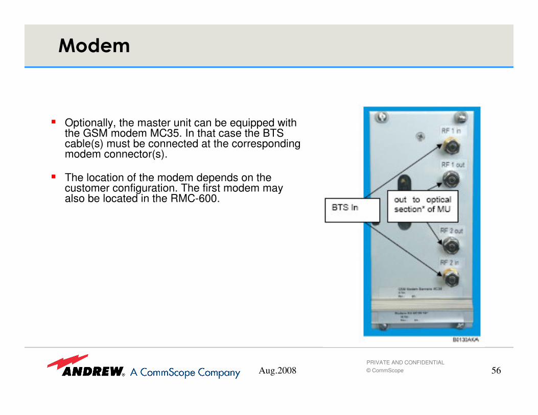
� Optionally, the master unit can be equipped with the GSM modem MC35. In that case the BTS cable(s) must be connected at the corresponding modem connector(s).
� The location of the modem depends on the customer configuration. The first modem may also be located in the RMC-600.

Aug.2008 57PRIVATE AND CONFIDENTIAL© CommScope
/�������������� �
� ���������*������������������������!�+��������������*�)����**���
� �����������!�������*�.��������������!��������������������������!���������!���

Aug.2008 58PRIVATE AND CONFIDENTIAL© CommScope
/�������������� �
� Hard wired installation of mains supply for the unit requires an easily accessible separation device in the mains circuit.
� Make sure that an appropriate circuit breaker and an overcurrent limiting device are connected between mains and unit.
� A connection of mains supply to a power socket requires the power socket to be nearby the unit.

Aug.2008 59PRIVATE AND CONFIDENTIAL© CommScope
$ ������ ����
� In order to switch on the unit, switch the AC primary switches (one for each power supply) to position ON.
� The power supply units are counted from left to right (1-8). Also, switch the DC switches of all equipped subracks to position ON.
� A mini master unit operates without an ON/OFF switch, thus for power supply, connect mains.

Aug.2008 60PRIVATE AND CONFIDENTIAL© CommScope
$ ������ ��������).���������������
� Each transceiver is equipped with a display showing its address (or an Error indication).
� Set the address by using the “Mode” button to choose the digit to be set, adjust the digit with the “Set” button and confirm with the “Mode” button when the desired value is reached.
� For addressing transceivers of a cascaded system, observe that addresses may only be set according to the following table.
� The addresses of the connected remote units will be set automatically.

Aug.2008 61PRIVATE AND CONFIDENTIAL© CommScope
$ ������ ��������).���������������

Aug.2008 62PRIVATE AND CONFIDENTIAL© CommScope
$ ������ ��������).���������������
� To commission the system, the optical transceivers must be removed for levelling. Before, the DC switch of the corresponding subrack must be switched to position Off.
� To remove the transceiver, loosen the four captive screws by which each transceiver is fastened to the subrack. Use the grip to pull the transceiver out.
� For levelling, plug in the levelling adapter* that is part of the delivery at the position of the transceiver and fasten it with the two captive screws. Connect a spectrum analyzer to the band connectors of the adapter. The adapter connectors are SMA female, thus the spectrum analyzer requires SMA male.
� * If no levelling adapter is available, connect a spectrum analyzer to the DL band ports at the back of the subrack. The band ports are SMS male connectors, thus the spectrum analyzer requires SMS female. Connect the base stations one after the other at the port connectors (P1-P4, corresponding to their software addresses) of the respective band combiner** – or, depending on the individual customer configuration, at the connectors of the BTS-connects, splitters or modem – and adjust the DL level by means of the corresponding steplessattenuators*** until the required level is reached.
Aug.2008 63PRIVATE AND CONFIDENTIAL© CommScope
6������� �����������������
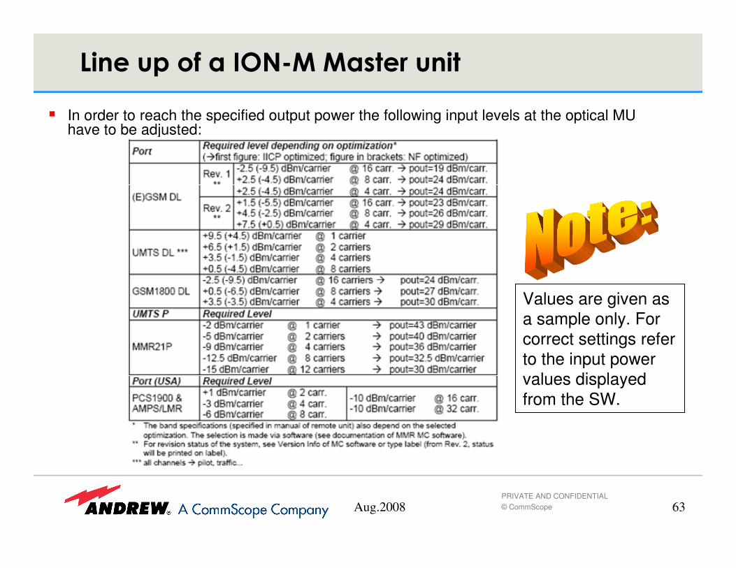
� In order to reach the specified output power the following input levels at the optical MU have to be adjusted:
Values are given as a sample only. For correct settings referto the input power values displayedfrom the SW.

Aug.2008 64PRIVATE AND CONFIDENTIAL© CommScope
6������� �����������������
� In order to reach the specified output power the following input levels at the optical MU have to be adjusted:
Values are given as a sample only. For correct settings referto the input power values displayedfrom the SW. Theyare depending on installed HW and SW in your system.

Aug.2008 65PRIVATE AND CONFIDENTIAL© CommScope
$ ������ ������*
Variable attenuators:
Red mark at start and stop position.
� Note: The probe ports are only for general measuring purpose, not for levelling the system. The levelling has to be carried out as described in the following.

Aug.2008 66PRIVATE AND CONFIDENTIAL© CommScope
$ ������ �������*�%�&
� Measurement points at Master Unit subrack
� Connect your spectrum analyser to the appropriate ports in order being able to adjust the levels for each band given in the following table. The optical loss on the link to the RU is compensated by the auto levelling software.

Aug.2008 67PRIVATE AND CONFIDENTIAL© CommScope
�������������
� For the MMR system only a reference levelhas to be adjusted in DL path.
� For levelling purpose a measurment adapter isavailable.
� It offers quick and simple access to themeasuring ports at the MU - DL
� It protects the MU RF connectors againstmechnical damage

Aug.2008 68PRIVATE AND CONFIDENTIAL© CommScope
� Note: Each transceiver is equipped with a display showing its address (or an Error indication). This address is pre-defined and factory-set. In case of an upgrade or change set the address as follows:
� Use the ”select/set” button to choose the digit to be set, adjust the digit with the ”counter”button and confirm with the ”select/set” button when the desired value is reached. Every address has to be unique in the system
� Note: Addresses from 1 to 124 are used for point to point connection (one Remote per OTRX)
� Addresses from 128 to 252 are used for cascaded remotes.
Grip
Select/Set Counter
Display
Connectors used for WLAN option
���)*���������������*

Aug.2008 69PRIVATE AND CONFIDENTIAL© CommScope
$ ������ ��������)
� The varying optical loss on fibres between MU and MMR is equalised by meaning of an auto-levelling function. This will guarantee always the same gain on the DL/UL path from Remote antenna connector to Master OTRX.This function is included in the system control software. This makes sure that, even if due to dirt etc., the optical loss increase the system performance is kept.
� The further system setup is done with this auto-levelling function.
� The autolevelling will be described in the software training.
eo
oe
Master Unit Remote Unit Connection to:
• Antenna or
• Radiating cable
Fibre

Aug.2008 70PRIVATE AND CONFIDENTIAL© CommScope
1� ��������1� ����������
� In order to guarantee required system performance, the gain in UL/DL is unbalanced. (UL gain is higher than DL gain) The BTS settings have to be performed in a way as if working with TMA.
� If this is not wanted, a fixed attenuator may be fitted in the UL path inside the MU, or the auto-levelling may be switched off and attenuations are set manually.

Aug.2008 71PRIVATE AND CONFIDENTIAL© CommScope
� Due to auto-levelling the gain is kept constant, no matter about optical attenuation on the fibre link MU - RU (max. 10 dB opt.)
� For Rel. 2, Rev 2 systems in following the DL gain is given:
Optimisation IICP NF
GSM 900 MHz 21,5 dB 28,5 dB
GSM 1800 MHz 26,5 dB 33,5 dB
UMTS 23,5 dB 28,5 dB
� UL gain is given before, dependent on optimisation
1� ����������+�� � �� �(�

Aug.2008 72PRIVATE AND CONFIDENTIAL© CommScope
1���������������������
� Alarms generated in the RU areforwarded through the fibre to theMU.
� Fibre failures are monitorred by theMU and the RU
� Processing for all alarms are donein the MU (RMC)
� Alarms and status information maybe forwarded by modem to theOMC or via the alarm board to theBTS / Node B

Aug.2008 73PRIVATE AND CONFIDENTIAL© CommScope
)�� �*���1���������� �
� Following alarms are indicated from LED atconnector flange:
� LED off: no power
� LED green: No alarm
� LED yellow: Alarms not directly related to RU
» External alarms
» Optical RX alarm
» all ALC alarms
� LED red: Alarms directly related to RU» Power alarms 12 & 28 V
» Temperature
» Fan
» I2C Bus
» Optical TX alarm
» Amplifier „power down“

Aug.2008 74PRIVATE AND CONFIDENTIAL© CommScope
1��������������� �������%�1'&
5�� 4���������� E
��0,6�����+��� ���
��8
:����*����
������ �����!���
��8�
The SAB is used to forward and receive alarms to/from externalconnections (p.e. Node-B, BTS, shelter doors)

Aug.2008 75PRIVATE AND CONFIDENTIAL© CommScope
1��������� ������ ���
� SRMU Alarms
– Fibre optic RX/TX alarm
– Bus I2C failure
– System temperature
– Fibre optic DL/UL current
– Unit unavailable
�����������������+��������� �����*�.����������������������+� #*����������������

Aug.2008 76PRIVATE AND CONFIDENTIAL© CommScope
1��������� ������ ���
� RU Alarms
– Fibre Optic RX/TX alarm
– Power supply 12/28 V failure
– Fan failure
– Bus I2C failure
– System temperature
– External 1...4 alarm
– Fibre optic DL/UL current
– Optical loss has changed
– Optical loss out of range
– Amplifier 1...3 failure
– Amplifier 1...3 ALC DL/UL alarm
– Unit unavailable
– External 1...4 output
�����������������+��������� �����*�.����������������������+� #*����������������

Aug.2008 77PRIVATE AND CONFIDENTIAL© CommScope
��� (
� The following training section are dealing with:
– Maintenance
– Alarmhandling
– Software introducion

Aug.2008 78PRIVATE AND CONFIDENTIAL© CommScope
1�2)/,�$�)-�)1����
#������*�������F�����+�����������