AND MEASURING GEAR - American Radio History:...
76
IN' THIS NENN TEST AND MEASURING GEAR IssUE : www.americanradiohistory.com
Transcript of AND MEASURING GEAR - American Radio History:...

IN' THIS NENN TEST AND MEASURING GEAR IssUE :
www.americanradiohistory.com
Advertisements Wireless World February 1946
Components 6etyo caw -
made by the organisation with the greatest experience
BRITISH. GEORGIAN HOUSE, BURY STREET, ST.JAMES'S
LONDON S.IW L ENGLAND
www.americanradiohistory.com

February 1946 = Wireless World Advertisements i
AOOEL 7 tr,VERSAL L..OMETER
.Epfü ñ /.
1.còEL:.Ä'..,.''. UHVEi,AL A oMsTER
THE AVO" VALVE TESTER
THt A:.A WAVE ... ..
"AVO" OSCILLATOR
HE world -wide use of E A V O ' '
Electrical Testing Instruments is striking
testimony to their outstanding versatility,
precision, and reliability. In every sphere
of electrical test work they are máintain-
ing the "AVO" reputation for dependable
accuracy, which is often used as a
standard by which other instruments are
judged.
THE AUTOMATIC COIL WINDER & ELECTRICAL EQUIPMENT CO., LTD. W I N D E R H O U S E D O U G L A S S T R E iE T L O^I m O N S W I TEL VICTORIA 3404/7
A
www.americanradiohistory.com

2 Advertisements Wireless World / 'buifar.l I (40
A few useful
items from our Comprehensive Stock
EPICYCLIC reduction gears, ratio 5 -1
WESTINGHOUSE Metal Rectifier -type HI fhlf -wave, 3.5v
2 0 15 mA, useful for meter work
RELAYS sensitive, operating on 57v. -SmA, re-
sistance 12 6 15,000 ohms
SCREENED CONNECTORS
2 9
for octal top -cap
PUSH- BUTTON UNITS 6-way, complete with escutcheon, etc. 8 6
KEYS Operating keys, G.P.O. bar types, 28/6 LI
2 0 Practice Keys, moulded bakelite 5 0
G.P.O. bar type 3 6
U.S.A. streamline metal
CONDENSERS T.C.C. paper 4 mfd. 750v, working 7 6
BROWN'S TELEPHONES Lightweight, 2,000 ohms LI 4 6
0 6
U. S. W. COMPONENTS
For 5 metres (and below) refer to EDDYSTONE LEAFLET available on request. Send 2;d- stamp.
Use
DURALUMIN TUBE for your 5 -metre aerial available in
8 toot lengths. 4/- each.
but CALLERS ONLY !
WEBB'S RADIO 14, Soho Street, Oxford Street,
London, W.I - - - GERrard 2089 Telephone
We are available 9 a.m- till 6 p.m. for OFFICIAL business,
but please note our SHOP HOURS -9 a -m. to 5 p.m.
(Saturdays, 9 a.m. to I p.m.)
the jalZZUrLts arc S mow TCI -/ Available in a wide range of circuit combinations for Radio. Television and other applications.
Manufactured by
BRITISH N.S.F. CO. LTD. KEIGHLEY, YORKSHIRE
(Sole Licensees of OAK Manufacturing Co., Chicago).
M.R. SUPPLIES now offer from stock the following useful range of brand new RECTIFYING and
other ELECTRICAL EQUIPMENT. Prompt despatch. Ali prices nett. S.T.C. METAL RECTIFIERS (Selenium). For battery charging up to 12 voila lu
conjunction with uitable Transformers (see below). 1.6 amp.. 12/6 ; 3 amps.,
22/8 ; 6 amps., 89/8: to amps., 49/8 (despatch last 2 items 2/ -). Also a few
24 volts 80 amps., £10 10s. (despatch 3/ -). Also small relay -operating or bilge
type, 25 volts 75 m -a- (half- wave), 4/6 ' 25 volts 76 ma. (bridged -full wave), 7 /6. Small make fLT. RECTIFIERS 240 v. 60 m.a. 16/6 ; 320 v. 60 Mil 19/6 (For field excitation or anode supply.)
p STEP-DOWN and
1MAAIHS 2
TRANSFORMERS. .
AI 20/- arse , 2nd404 v. at(Lapped). a p amps. )
(for 22/6 rect.), 32/8. Sec. 6, 12 and 17 v. at 6 amp.. (`or 39/6 rect.). 49/6.
SLIDING RESISTANCES, fully enclosed, 4 ohms 6 amps, 10 ohms 3 amps 50 ohms
1.4 amp, 100 ohms 1 amp. 200 ohms 0.7 amp 400 ohms 0.5 amp, any one 25/ -. Also 1100 ohms 0.375 amp, 29/8. Also 6000 ohms 0.26 amp 65/- (deep. 2/61. Also
500 ohms 1 amp, 59/8 DIMMERS. with hand -wheel control (2201240 v.), 1000 watt,
£6 17s. 6d. ; 1500 watt, £8 Ss. ; 2500 watt £9 17e. lid. (des. either 7/6 plus
20/- for reto -nublo eagle).
L.F. CHOKES. 10 h. 150 ma. (150 ohms) 18/8 ; 15 h. 100 ma. (320 ohms). 12/8. CONNECTING WIRE (Hamofill. Rubber covered 20 SWO tinned copper in various
colours, 18ít. coils, 11- ; 6 coils for 5! -. Spec. price for quantities In length.
SCREENED CONDUIT, woven, flexible rein'erced }in. bore, 1/9 yard ; }in. bore,
2/9 yard. CO -AXIAL CABLE, best quality 2/9 yard. SCREENED WIRE. single
20 SWO conductor, 4d. yard.
ROTHEBMEL -BRUSH PIEZO- CRYSTAL MICROPHONES 0.104 specially homed with knuckle -joint mount with Eft. screened lead 78/8. Also special miniature piezo -Crystal Microphone Inserts, Ilin. din 20,6,
GRAMPIAN MOVING COIL MICROPHONES, 15.ohmo imp. mounted in square
euspenslon frame, One performance, £4 4e. FLOOR STANDS Golding), all throw. ext. to lit. lin., 47/6. LOUDSPEAKERS (first-grade models only offered). VITAVOx, high fidelity, 12in. P.61. Units, 15 ohms coil, K12 /10 (10 watt) £7. K12/20 (20. watt), £11 (deep. either 6/-1. VITAVOX RI -TONE, £31 10e. (deep. 6/1 G.E.C. 8 watt
P.M. In 10 }in. dual -direction metal drum with mounting bracket end fitted tapped
transformer, 75/- (deep. 2/6). PROJECTOR SPEAKERS. Vitavox 10 -watt P.M.
Unit (15 ohms) with 30in. all -metal Horn £6 17s. 8d- (deep. 7/61.
PYROBRAZE ELECTRIC SOLDERING AND BRAZING EQUIPMENT, 200 /250 v.
A.C., complete instruments, ready for use- No. l (Portable) 3/5 minute rating,
30/120 amps, £12 10s. No. 2. also suitable for welding up to 18 SWO metal sheet,
20/30 minute rating. 30/130 amps, £16 10s. (deep. either 6/ -). Further details
upon request. RELAYS (P.O. type, brand new), 200 ohms col, 8.p -on. nwitch:ng, 7'6.
TOGGLE SWITCHES, soap action, 5 amp 2/- each, 20/- dozen.
S.T.C. SOLDER resin -cored 13 SWO, 40 p.c. tin 1 lb. reels, 48. ROTHERMEL PIEZO -CRYSTAL PICKUPS, senio- mode. with black bakelite arm,
78/9. STROBOSCOPIC SPEED TESTERS (30 c.), 78, 79 80 rpm, 1/ -.
IN STOCK (inspection invited): GRAMPIAN 15-watt AMPLIFIERS RsTHERMEL
8-watt AMPLIFIERS, STANDARD COMBINED MEASURING INSTRUMENT (by
Hartmann & Braun- Oermany) O.C. volts, milliampa and amps (11 readings),
0.1 per cent. accuracy. Please include sufficient for despatch where not stated
M.R. SUPPLIES, 68, New Oxford Street, London, W.0.1 T.'ephorr. r MUSeum 2958
www.americanradiohistory.com

February 1946 Wireless World Advertisements 3
DUBILIER ELECTROLYTIC CAPACITORS AGAIN
,
AB
ER
LE
o+4
"DRILITIC" C A P A C I T O R S
OUT of evil - good ! The destruction of our Electrolytic Capacitor Depart- ment by German bombs was a first class disaster at the time both for us and our customers. But it has led to two great advances :
We have desi ned an entirely new series of electrolytic capacitors, smaller and more efficient than any previously available. And we have fortunately been able to install completely new plant for their manufacture.
Capaci- tance uF.
Working Voltage
max.
Type No.
Retail Price
EACH
Size __-
Dia.
ins. -
L.
Terminals Ripple
Current max. m.a.
Capacitance tolerance
5o
S
5o
Soo
BR.Sos
BR.85o
3/6
4/-
ß 2
z
z' long 20 SWG Tinned Copper Wires
too
too
- 0.0% + 150%
- o.o % + 75%
DUBILIER CONDENSER CO . (1925) IID. SSthe pcíteeta
c.tt.C.s
www.americanradiohistory.com

4 Advertisement:s
STATIC TWO - DIMENSIONAL visual delineation of any recurrent law. RELATIVE TIMING OF EVENTS and other comparative measure- ments with extreme accuracy.
PHOTOGRAPHIC RECORDING of transient phenomena.
SIMULTANEOUS INDICATION of two variables on a common time axis. INDUSTRIAL INDICATING and TESTING afford in- creasing scope for the Cathode Ray Tube as the only device with the above inherent features of which the last is unique in the Cossor DOUBLE BEAM Tube.
The Model 339 Cossor Oscillograph thus equipped is invaluable on all problems of research, production or operational testing, when the effect examined is
applied as a voltage. When recurrent the traces are studied visually and when transient are recorded photographically, using Model 427 camera.
A. C. COSSOR LTD., INSTRUMENT DEPT
Cossor House, London, N.5. 'Phone : CANonbury 1234 (33 lines). 'Grams: Amplifiers Phone London.
Wireless World February 1946
M.G.1, 2 or 3 GANG
CONDENSER This small size condenser is of rigid construction, and is made in various capacities up to 540mmf. with tropical finish. It can be supplied with trimmers built in if required. The 2 Gang Frame i s 2 "xl ( i "x21'," over all.
JACKSON BROS (LONDON) LIMITED KINGSWAY WADDON SURREY
TELEPHONE: TELEGRAMS: WALFILCO, CROYDON 2754-5 PHONE. LONDON
FOR THE RADIO SERVICEMAN
DEALER AND OWNER The man who enrols for an I.C.S. Radio Course learns radio thoroughly, completely, practically. When he earns his Diploma, he will KNOW radio. We are not content merely to teach the principles of radio, we want to show our students how to apply that training in practical, every -day radio service work. We train them to be successful ! Special terms for Members of H.M. Forces and
discharged disabled members of H M. Armed Forces
You may use this Coupon.
INTERNATIONAL CORRESPONDENCE SCHOOLS Ltd. DEPT. 38, INTERNATIONAL BUILDINGS, KINGSWAY, LONDON,WC.2
Please explain fully about your Instruction n the subject marked X
Complete Radio Engineering. Radio Service Engineers Elementary Radio.
And the following Radio Examinations :- British Institution of Radio Engineers.
P.M.G. Certificates for Wireless Operators. City and Guilds Telecommunications.
Wireless Operator and Wireless Mechanic, R.A.F.
Name Age
Address
www.americanradiohistory.com

February 1946 Wireless World
WORLD'S LARGEST RADIO
COIL MANUFACTURERS RADIO FREQUENCY INDUCTORS INTERMEDIATE FREQUENCY
TRANSFORMERS RADIO FREQUENCY COIL
CHOKES MICA COMPRESSION
CONDENSERS AIR DIELgCTRIC CONDENSERS MICA MOULDED CONDENSERS SICKLES SILVER CAP
CONDENSERS GANGED PERMEABILITY TUNING COMMUNICATIONS EQUIPMENT F.M. EQUIPMENT PARTS U.H.F. RADIO EQUIPMENT SPECIAL ELECTRONIC
EQUIPMENT
The F. W. SICKLES Co. CHICOPEE, MASS. U.S.A.
RAYTHEON "FLAT" Hearing Aid Tubes
So tiny they must be built under high powered magnifying glass . .
just as a jeweller assembles rare gems in a costly brooch. They're the hearts of famous hearing aids, providing ut- most clarity and richness of tone.
RAYTHEON MANUFACTURING COMPANY
NeASIN AID tues DIVISION
P. R. MALLORY & CO. Inc.
MALLORY VIBRATORS ARE ALWAYS DEPENDABLE
Along every front Mallory has pioneered in Vibrator design to ensure safety, depend-
ability and long service. Mallory offers syn- chronous and non -synchronous Vibrators for 6, 12 and 32 volt input, also a complete range of "STRATOSPHERE " Vibrators plus the world- famous Mallory " VIBRAPACK " (Reg. Trade Mark).
* Vibrapack is a registered trade mark, the property of P. R. Mallory & Co., Inc. Indianapolis, U.S.A. Units which do not bear this trade mark are not o {enuine Mallory manufacture.
P. R. MALLORY & CO. INC. INDIANAPOLIS, INDIANA,
U.S.A. Radio and Electronics Division
ALSO
-` MYKROY" CERAMIC INSULATING MATERIALS GENERAL ELECTRONIC VACUUM CONDENSERS
FOR THE FUTURE These Manufacturers will help solve you post -war problems. Register your name now for full details which will be sent you when supply conditions again permit.
FRAN K HEAVER
LIMITED Kingsley Road, BIDEFORD
N. Devon
Advertisements 5
VICTORY PRODUCTION
TYPE 2600 MIDGET VARIABLE CONDENSER
WE are now ready to help win the peace by making the best use of
the still greater knowledge and experi- ence gained in the manufacture of variable condensers, mechanical tuners, drives, etc
THE GENERAL INSTRUMENT
CORPORATION
ELIZABETH, N.J., U.S.A.
RADIO
AIR CONDITIONING
HEATING and
REFRIGERATION
EQUIPMENT
DOMESTIC
APPLIANCES etc., etc.
Ad. Auricma, Inc. Manufacturers' Export Managers
89 BROAD STREET, NEW YORK, 4 N.Y.
U.S.A.
B
www.americanradiohistory.com

6 Advertisements Wireless World February 1946
Ilia4P zonewt _ a/,zd tie
MIKE / THE
man you know. The moment ) Well, it was always " a moment " when he spoke. And
the mike, just one of the hundreds of thousands that Goodmans supplied to the tanks, aircraft and for the field. Designed by Goodmans, they incorporate the first massed -produced MOVING COIL Microphones and Earphones. History was made when, as we were working to capacity, hundreds of thousands more of these instruments were made to the original Goodmans' specification in the U.S.A., Canada, and South Africa.
These instruments are destined to find an important place in the more peaceful pursuits of the tomorrow for P.A., Concert Work, etc.
MICROPHONES & EAR PHONES
GOOD MANS INDUSTRIES LTD LANCELOT RD WEMBLEY MI DD
Wharfedale OUTPUT
TRANSFORMERS
PRODUCTION in recent
years against Admiralty Contracts has set even higher standards to Wharfedale Components. From this both trade and public will benefit.
P TYPE
O.P.3 -
PRICE - 3 ratios
LIST - - 5/6
P Type - - 4 with C.T. 6/6
G.P.8 - - 8 99 ,. - 9/6 Universal - 6 Wander Plug 12/6
W.12 - - 3 C.T. - 17/6
WHARFEDALE WIRELESS WORKS HUTCH INSON LANE, BRIGHOUSE, YORKS.
'Phone : Brighouse 50. 'Grams : " Wharfdel, Brighouse.''
GALVANISED SECTIONAL STEEL
RADIO MASTS Sendforeale /ogue W0/330
TVBURN R? ERUINGTON
POLES LTI3 - BIRMINGHAM 24
www.americanradiohistory.com

c euruury 1940 wireies or><a Advertisements 7
ELECTRONICS
The G.E.C. Cathode Ray Tube 4103 is a
type widely used in
industrial test gear.
made it possible/ The testing and maintenance of the tremendous range of electronic equipment produced for the fighting services, called
for the production of many highly specialised testing devices.
Equipment had to be available both for day -to -day servicing in
the front line, and more detailed overhaul in service workshops and factories in the rear. A large proportion of such test
equipment was valve operated and OSRAM were in the forefront of this new technique, which will bring to the pursuits of peace
many well -tried electronic devices to speed, smooth and make
safer our way of life.
Advt. of The General Electric Co. Ltd., Magnet House, Kingsway, London, W.C.2,
www.americanradiohistory.com

8 Advertisements Wireless World February 1946
EQUIPPING A LABORATORY?
0/1/ 4a//' ¡G Time and time again experience has shown that a consider-
able saving of time and money could have been made if
Marconi Instruments had been called in at the very earliest
stages of equipping or re- equipping a scientific laboratory.
All too often it is found that vital instruments have to be
installed almost as an afterthought when it is too late to
site them in the most logical and convenient place. All too
often it is found after several measuring instruments have
been installed that a single piece of Marconi apparatus
could have done the work of them all.
Consult Marconi Instruments from the start -it costs
nothing and may save a great deal of time and money.
MARCONI INSTRUMENTS LTD. ST. ALBANS, HERTS. Telephone: ST. ALBANS 4323;6 Northern Office: 30 ALBION ST., HULL. Telephone: HULL 16144
Purchase your RAYMART products from - ABERTILLERY, Mon... OOutline Radio Service, 33 Somerset Street.
ASHBURTON- U -LYME Ashton Radio Repair Service, 33 Mill Lane.
BOURNEMOUTH BOURNEMOUTH BLACKPOOL .. BURNLEY BELFAST BRIGHTON ..
BRADFORD ..
BOLTON BIRMINGHAM .. CHATHAM CHATHAM .
CHILWELL, Notts.
W. G. Hodges, S Lincoln Avenue. Wireless Supplies Unlimited, 264 Old Christchurch Road. R. Maynard (Blackpool), Ltd., 129 Bloomfield Road. T. B. Wimbush, 27 -29 Canning Street, Stoneyholme.
,. S. A. Fisher & Co., 17 -19 Queen Street. .. R. Ransom, 34 Bond Street.
Super Radio Ltd., 2 Bank Street. S. Bayliss, 216 St. George's Road.
.. Johnsone Radio, lb Hall Green Road, West Bromwich.
.. Bernards Radio, 67 High Street.
.. D. E. Hadaway, 97 Watling Street. A. Simmonds 40 Bramcote Avenue. J. W. Bevan Evans, The Aipary, Cadrant Park.
CHADWELL HEATH, Ex. Drury A Beardow, 45 Wangey Road. COVENTRY .. .. Electrad, 387 Stoney Stanton Road. EDINBURGH Buccleuch Radio, Malville Terrace. ENFIELD Howards (Enfield), Ltd., 8 Southbury Road. GLASGOW Ray -Lab, 438 Paisley Road, West Ibrox, S.W.1. HARROW Hudson Radio, 29 Onk
n Avenue Avenue, ue Fixbyne. HUDDERSFIELD Bill Sykes (Radio),
HANLEY, Staffs. R. Perry, 47 Lichfield Street. HAZEL GROVE G. E. Samwaye. 181 London Road. LONDON Berry's (Short Wave), Ltd., 25 High Holborn, W.0.1. LONDON .. Park Electric Co., 3 North Park Road, Brixton Hill S.W.2.
LEICESTER Frith Radio, 69 Churchgate. LIVERPOOL Super Radio, 116 Whitechapel. LEEDS Albion Electric_ 125 Albion Street. LEEDS Valiance & Davison, 144 Briggate. LOWTON ST. MARY'S .. J. Ince & Sons, 74 Newton Road (Lance) MAIDSTONE .. V. Chard, 20 Mill Street. MORECAMBE W. V. Leyland, Morecomhe Street. NEWCASTLE -ON -TYNE Payne & Hornsby, 3 Andrews House, Gallowgate. NUNEATON T. H. Salisbury, 50 Abbey Street. NUNEATON . C. A. Robinson, 116 Queens Road. NEWPORT, I.0.W, Sherratt & Son, 82 High Street. NEWCASTLE, Stalls. .. S. T. Chadwick, 61 George Street. OSWESTRY .. Powers Radin, Albion Hill. PUDSEY, Leeds .. Fairbanks, Sa Lowtown. RUGBY Benn Radio, Central Parade, 122 Hlllmorton Road. SWAFFHAM E. Wade, Market Place. SOUTHALL Gurneys, 109 The Broadway. SELKIRK .. J. P. B air, 35 Market Place.
RAYMART SEE NEXT MONTH'S ISSUE FOR FURTHER LIST OF RAYMART
AGENTS
48 HOLLOWAY HEAD, BIRMINGHAM I
Designers and Manufacturers of Radio
and Electronic Devices.
ROMAC RADIO CORPN. LTD.
Announce a range of AMPLIFIERS
12 watts -25 watts, built to a
quality specification as regards
performance, construction and to meet 'the requirements of the
discerning purchaser. Full details,
specification, price on request. The above can be delivered with Speakers, Microphones and Turn- table units if required.
THE HYDE ' HENDON ' LONDON, N.W.9
www.americanradiohistory.com
February 7946 Wireless World Advertisements 9
Made in Three Principal Materials
FREQUELEX An insulating material of Low Dielectric Loss, for Coil Formers, Aerial Insulators, Valve Holders, etc.
PERMALEX A High Permittivity Material. For the construction of Condensers of the small- est possible dimensions. TEMPLEX A Condenser material of medium per- mittivity. For the construction of Condensers having a constant capacity at all temperatures.
Bullers BULLERS LOW LOSS CERAMICS
BULLERS LTD., 6, LAURENCE POUNTNEY HILL, LONDON, E. C.4 Telephone: Mansion House 9971 (3 lines) Telegrams: "Bullers, Cannon, London" Manchester Office: 196, Deansgate, Manchester
www.americanradiohistory.com
io Advertisements
ARE YOU USING THE SLEEVING BEST TO SUITED THE JOB
" Best suited " means an insulating sleeving
that meets every Service or general require-
ment. The DE L A F L E X range includes
non -fraying Woven Fibre Glass and Tropical
Grade ROLLED SILK in a complete range of
colours and in sizes from 0.5 mm. to 35 mm.
Thus, a recommendation from De La Rue
Insulation Limited is unbiassed ... you get
the sleeving best suited to your needs, not
only from the standpoint of efficiency, but of
economy as well. Fullest details, samples
and prices gladly sent on request.
DelafleX ikeeftdef
DE LA RUE INSULATION LTD 84 R E G E N T S T R E E T L O N D O N W.1
T E L E P H O N E . R E G E N T 2 9 0 1
m 180.-`11L- <., m
Wireless World February 1946
.=" R O L L ED S I L K
M E T A L S C R E E N E D
V A R N I S H E D C O T T O N
WOVEN FIBRE GLASS V A R N I S H E D ART SILK
R. A. BOTH ERMEL LTD. are now in production for the well -known
Piezo Electric Products.
PICKUPS MICROPHONES
HEADPHONES THE HUSHATONE
DEAF AID MICROPHONES CONTACT MICROPHONES
A.C. AMPLIFIERS
Send for informative literature.
NOW READY !
A specially designed A.C. Amplifier, Type V.R.2, rated at 41 watts, is available from stock, for use in connection with all types of Crystal Microphones and Crystal Pickups. For many years R. A. ROTHERMEL Ltd. has
made intensive research in Amplifier design, and
we confidently present the V.R.2 as represent- ing the ultimate in qual.ity of reproduction, workmanship and material.
Write for Bulletin.
R. A. ROTHERMEL LTD. ROTHERMEL HOUSE, CANTERBURY ROAD, KILBURN, N.W.6
Telephone : Mdida Vale 6066 (6 lines).
M1NIATURQr MIDGET
We specialise
in their
anufacture
ínafuns;
THE SCIENTIFIC VALVE
BRITISH MADE
r. "'es sr MARROW
HIVAC LIMITED. Greenhill Crescent, Harrow on the HiII. Middx. Phone: O ,
www.americanradiohistory.com

February 1946 R "irele%% World Advertisements zi
RADIO FREQUENCY
CABLES
?,¡'j-g Ari},`Y4A.-rï- r. ,
1)l:if'tlï'it sow
9 il\,t'11L llllü nir'l 1 l
t
W. ..i1 r 1t i
t
t-} Ii(,. i11. {} : , t .:
,(( No,
.n7 {`n-m{ 1idear,]'ul qSmb,.t.d. (td t t-..th.r il
t ilaa t 4 {tt i-.rI a,,-. la]r } a]d.
li( { S
tt ith ht ti t,..te ].
ilu eic trt. P xdntt { {]., sl'n tiç}..cG1 .n t
d 1hh 'ri` tht
. }.q y .(
L]crc +
d S1csi1 t. ..-n'n''`S ..>gP.f'aore. t.nnütn]n nn
1 rìanrtS
OT pt ' th.. rík, t^. .o( i
4rfaitic( t.itl(
1i ,.t rad"- t antS . it. ,uc]a 11174 AC e* Srcgnru'
Pa. w.t.eìae ít Ira- ..TOrnr+,ï
te.n ytet]a.(( thr ..
1i a tlrxfldc n(t,(.t f+-iaattx dHOt tn ('` 1 r1 ' t 'a (
ta r- rrsntan . -trd { ] ..l S.. 11. ..
(] gre.t7_ -tl` th. nit -Aibfe t` y.. il.
hrau{wg and, r d tfi. ;S(1t of tie' <)n ay{ t.ali(Ttd`
1{n'i tow]d ea{ ]bt ti
11(..11 t uS ¢ S r 4. 1
<u-SL-lhh ,.t
i ]( .tallí. {ayer . ti i u,,ttl,ic
` .
f _ .(i brnld
n]in3ft. :t1.((s.' m ch ' _ tt.,(,
tatk( Srat{ a ,y. ..4,tr acri 3t1(cd .ua<uri.t.c.
of 1
totn, at]c. c(.1{if, rt.att.nu+
'Cln dinK]y'wn' ,1cì }t t t}(r . ' e.a'. "-
¿'qes Cltas(q,na . "
vo -o t P ;
air 1:+f a. y(,{ 111'11
AV }H r taat lt
on p.tl.r, yrz n( ì . { cal'to, it]. -t id't (.t
(1 1116.11 et
Idrl(' {1,,tn.n°`1 t..r(1 lilt I" 't1,b.t (
.,id(üom.l,d{a.(
çi(.trara'tkda y. fill
\I{c7];a.trlr`ú. -
01, 10, .tailu.cxKrc.
Have you had a copy of this new book - the first of its kind giving comprehensive technical and catalogue data on radio frequency cables ?
Ask for Publication No. 141.C.
BRITISH INSULATED CALLENDER'S CABLES LIMITED NORFOLK HOUSE, NORFOLK STREET, LONDON, W.C.2.
www.americanradiohistory.com

I2 Advertisements
PULLIN INSTRUMENTS
SERIES 35 for panel mounting or as bench instruments.
Available either as single range panel instru- ments or mounted in sturdy bench stands, as
illustrated, with up to three ranges self -con- tained. Scale length 3Y. Instrument size, 4ö "x4á "; panel opening 3 ".
Can be supplied (I) Moving coil - micro - ammeters, milliammeters, ammeters, milli - voltmeters, voltmeters, ohmmeters, decibelmeters.
(2) Rectifier - microammeters, milliam- meters voltmeters, decibelmeters.
(3) Thermocouple - milliammeters, am- meters, voltmeters. All available in all standard ranges.
MEASURING INSTRUMENTS (PULLIN) LTD
Please address all correspondence to : Phoenix Works, Gt. West Road, Brentford, Middx. Ealing 0011.
Wireless World February 1946
.;.+++++++ +- f f
THE STATIC f f
+
f f f
+
+
f f f f f f f f f f ( .;.-
CONDENSER Co. Ltd.
* Manufacturers of
STATIC CONDENSERS
TOUTLEY WORKS, WOKINGHAM, Berks
Telephone: WOKINGHAM 708
PERSUHALITY
by
P.A.
/\\
THE
DIFFERENCE THE
MIKE MAKES War - shortage of sensitive micro- phones has caused mass murder of "personality " over many workshop
sound -systems. Even the works - manager's voice giving staff -talks has been unrecognisable. But now Grampian are able to re- lease again the Grampian Pressure Microphone Type M.C.S., there is no longer any excuse for poor " local " transmissions. Replace the war -emergency " mikes " you
have been using in any P.A. sys- tems you maintain with the high -
sensitivity Grampian Type M.C.S., and get rid of one of
your worst sources of trouble. GRAMPIAN SPEAKER Projector Type PVH. Unit Max. Loading 10
watts. Impedance 15
ohms. Horn, length 42 In., diam. 24 In. Cut
GRAMPIAN MICROPHONE TYPE M.C.S. Pressure operated. Swivel stand -adap- 7 tor. Frequency 70- 8000c. Impedance £ I . 5 20 ohms. Sensitivity 42 d.b. PRICE
£135 PRICE LOUDSPEAKERS Available Jor early auzxr,r-.
GRAMPIAN REPRODUCERS LTD., Hampton Road, Hanworth, Middlesex. Phone : Feltham 2657
Scientific G.6A
www.americanradiohistory.com
February 1946 Wireless World Advertisements 13
specifg FAEQUENTITE The range of Frequentite components covers more than a thousand pieces of every shape and size. Before finalising the design of new components consult
STEATITE & PORCELAIN PRODUCTS LTD Head Office : Stourport -on- Severn. Worcs. Telephone : Stourport 111 Telegrams : Steatain, Stourport
S.P.i7
www.americanradiohistory.com

14 Advertisements
Technical Reasons Why
Is the Finest Cored Solder in the World
3 CORES OF FLUX
Three Cores of Flux ensure flux con- tinuity. No lengths without flux are wasted. Consistent high quality joints are obtained with comparatively unskilled labour. Exactly the correct proportions of solder to flux are provided. Separate fluxing operations are obviated and no
extra flux is required. The three cores of flux being evenly distributed over the cross section of the solder provide thinner
solder walls than otherwise. This gives rapid melting and
speeds up soldering. The flux does not tend to run out of
the cores ; so there is always a supply available for the next
joint. The utmost economy of solder and flux is achieved.
Ersin, contained in the three cores of Ersin Multicore Solder, is the fastest non- corrosive flux. Possessing all the non- corrosive advantages of rosin, it enables joints to be speedily made on oxidised or " difficult " surfaces such as nickel. Ersin not only avoids oxidation during soldering but removes surface oxide already present -this is particularly advantageous in respect of materials that
have been in stock or apparatus that is being serviced. The use of Ersin Multicore, with correct soldering technique, avoids " HR " or dry joints.
10 SWG
22 SWG Double actual size.
Ersin Multicore Solder is made in most gauges between IO and 22 S.W.G. (128- 028 ") (3.251 -7109 m /ms). For general radio and electrical production and maintenance 13 and 16 S.W.G. are in most demand.
Five alloys of Ersin Multicore Solder, made
Virgin from virgin metals, are available -all antimony free. Under present circum-
Tin & Lead stances 45% tin and 55% lead is the most widely used alloy.
Technically, Ersin Multicore Solder other cored solder. A practical laboratory or production test will demonstrate this and show you that it is the most economi- cal solder to use. The majority of British and overseas manu- facturers already enjoy the advantages of Multicore. If you do not, and are engaged upon Government contracts, write for further technical information and free samples.
is far superior to any
Single reel rate nominal 1 lb. reels.
13 SWG - 4/10 16 SWG - 5/3
Above prices subject to usual trade discount.
} cwt. -ton lots at bulk rate. 6d. cartons for home use, available at most good radio and electrical dealers, ironmongers, etc.
MULTICORE SOLDERS LTD. Mellier House, Albemarle St., London, W.I.
Tel.: REGent 1411 (P.B.X. 4 Lines).
Wireless World February 1946
I _I _At1r "IUCIIr 1lll- IONIC" RANGE OF
ALMOST DISTORTIONIESS AMPIIEIERS
Here are performance figures, inclusive of out- put transformer, for the type 15 : - TOTAL DISTORTION, including hum and noise, for 15 watts output - 1,000 c.p.s. - 0.10/ (one -tenth of one per cent)
60 c.p.s. - 0.2% (one -fifth of one per cent)
FREQUENCY RESPONSE: level within 0.25db. 20- 20,000 c.p.s.
LOAD DAMPING FACTOR: 20 (10 times better than for average Class A triode).
GAIN : The basic amplifier requires 05v RMS at grid impedance. An additional two stages can be supplied built into the chassis, thus reducing the input to 0.005v R.M.S.
Full information on leaflet S.15
SPECIAL NOTE : The above figures establish such radically new standards that they may occasion some surprise. We therefore wish to stress that no error appears in this announce- ment. The circuits are original, and result from war - time research in our laboratory.
H J. LEAK P. COMPANY LIMITED 470 UXBRIDGE ROAD LONDON W.I2 T E L E P H O N E : S H E P H E R D S B U S H 5 6 2 6
7 H ERL ARE TGttJt AMPtIf I E A?
FROM 5co500 WAITS 10. %t: iRiTY WORK
THE TRIX ELECTRICAL CO,LTD. 1.5. MAPLE PLACE, TOTTENHAM CT, RD.
LONDON. W.I. 7, I,' MUSEUM' 5817 C. ,, TRIX/SDIO. WESDO. LONDON.
www.americanradiohistory.com
February 1946 Wireless World Advertisements 15
CERAMIC
it70/yé CAPACITORS
Outstanding characteristics of U.I.C. Pot and Plate Capacitors are the high break -down strength, low loss factor, and small dimensions. Working Voltage: io KV D.C. only or 7.5 KV D.C. Peak +A.C. Working Load R.F.: Up to 25 KVA according to type. Max. Current: Up to 14 AMP. according to type. Range
of Capacitance: 5 pF to 1200 pF. Tested to Specification K i to. Full details on request.
UNITED INSULATOR CO. LTD. 12 -22 LAYSTALL STREET, LONDON, E.C.1 Tel.: TERminus 7383 (5 lines) Grams. : Colonel, Smith, London
ÿ';ß:t; ::i: Ï,.'.si
For absolute RELIABILITY
SHORT WAVE COMPONENTS
COIL FORMERS .
Moulded in D.L.9 insulating material with 8 ribs. Outside diameter I }in. and a winding space of 21in. Very useful for construction of efficient low loss inductances for Receivers and low loss Trans- mitters. Type 1002 Plain. Type 1003 Threaded.
COILS. Type 959." Above can be supplied with three windings (I aperiodic, I tuned and I reaction) providing a com- prehensive frequency cover- age from 9 -2000 metres.
London Agents :
WEBB'S RADIO 14 SOHO ST., W.1
,,. .a .,` :
H.F. and V.H.F. CHOKES. Wound on special D.L.9 former with rigid wire ends moulded in. Type 1010 and 1022 are section wound, 10H is single layer spaced winding.
1010 1.25 mH 20 ohms 50 m/A 1011 5.32 uH 1.33 50 m /A. 1022 1.5 mH 10.53 250 m /A.
Typel009. FLEXIBLE COUPLER. Free from backlash yet completely flexible. Banishes alignment troubles. D.L.12 Insulation and phosphor bronze spring arms. For }in. spindles.
Type 1018. GLAZED FREQUEN- TITE INSULATOR to facilitate carry- ing of high Frequency leads through metal chassis and screens with minimum loss. Cones are flanged at bottom to self - centre into the metal. A.2 B.A. rod is used as conductor. 3 }in. long, lain. diameter.
STRATTON & Co. Ltd EDDYSTONE WORKS, ALVECHURCH RD.,
WEST HEATH, BIRMINGHAM 31.
use-Th
All brass construction, soldered vanes for low H.F. resistance and heavily silver -plated to pre- vent oxidation. D.L.9 endplate ensures constant capacity. }in .
diameter extension spindle. Single hole fixing.
Min. Cep. Type. Air cap. swing.
1094 gap8m5m15 1129 10
6 b8
1131 22 5 170
www.americanradiohistory.com

16 Advertisements
Stentorian ABCI. ll%:rLé.
EXTENSION SPEAKERS
now available again FROM
29'6 The benefits of special -
Supplies are isation make possible limited so really amazing values. The efficient please be permanent magnet speakers, giving patient if your remarkably pleasant reproduction, dealer cannot are housed in most attractive supply im- cabinets, complete with VOLUME mediately. CONTROL.
CABINET MODELS AT PRESENT AVAILABLE
Minor Type MX (for Low Impedence Extension) MC (with Universal Transformer) -
Baby BX (for Low Impedence Extension) BC (with Universal Transformer) -
29/ 6 35, 6 43 6 496
WHITELEY ELECTRICAL RADIO C°LT9 MANSFIELD, NOTTS.
WHY YOU PREFER ACOUSTICAL -One of a serres
Since all pick -ups vary, the introduction
of some form of correction is essential
if the highest quality of reproduction
is to be obtained. To fully load, the
gramophone input of the M 31 Model
requires o.03 v.r.m.s., i.e., about zo db
more gain than is required by the
average pick -up, thereby allowing for
the introduction of correction circuits.
AGOLJSTIGAL MANUFACTURING COMPANY LIMITED
H U N T I N G D O N T E L E P H O N E 3 6 1
Wireless World February 1946
r Pl 1°!° V N¢°1°
t 9pt°tay,W
µ 0s 1;.1,510
'" 7so arst 6O 10
R eo 9°
óW° ts°0
I
U o a
Úvt Va
otu.
..«.
{ e4 0* M199
CO"' aE TS tr
CE RACK RD..SHERNHALLST. WALTHAMSTOW. ER. PNONE-LARKSWf)OD4366i
COSMOCORD LTD ENFIELD
www.americanradiohistory.com

Fclwturr y 1916
The
Wireless World Advertisements z7
TAYLOR A.C. BRIDGE MODEL IIOA
These instruments give quick and accurate measure-
ments of Capacity and Resistance. There are six
Capacity ranges covering from .00001 to 120 mfd. and
the Power factor can also be measured on each range.
Six Resistance ranges are available measuring from
I ohm to 12 megohms. This bridge is A.C. mains
operated and a leakage test is also available for detecting
leaky paper or mica condensers. Price f14 14s. Od.
Please write for technical leaflet.
4. RANGES OF CAPACITY RANGESOFRESISTANCE
Send your enquiries to :- TAYLOR ELECTRICAL INSTRUMENTS LT° Ta lor electrical instrument -old
419 -424 MONTROSE AVE., SLOUGH, BUCKS. Tel: Slough 21381 (4 lines) ' Grams: "Taylins ", Slough.
SOU SAVES TIME!
THE LARGEST ORGANISATION IN GREAT
The TANNOY LOUDSPEAKER SOUND SYSTEMS save valuable executive time, increase production, and ensure greater general efficiency. TANNOY design, manufacture, install and maintain sound systems of all types for Staff Location, Announcements, " Music While You Work " Programmes, etc., etc.
\TANNOYY 'THE SOUND PEOPLE'
GUY R. FOUNTAIN, LTD. 'TANNOY ' is the registered trade mark of equipment manufactured by GUY R. FOUNTAIN, LTD., Canterbury Grove, West Norwood, S.E.27, and Branches. 'Phone: GIPsy Hill 1131 (7 lines) BRITAIN SPECIALISING SOLELY IN SOUND EQUIPMENT
www.americanradiohistory.com

18 Advertisements Wireless World February 1946
®
7 po eo
©
THAT'S Fixed THAT! Type CA 725.
Fixing knobs to shafts. Sounds simple but if you're a radio manufacturer you know what a headache it can be. The Spire fixing was designed to solve that parti- cular problem. The CA 725 is made to measure for shafts of various diameters. Then it is snapped into position in the hub of the knob and the knob pushed straight on to the shaft. Don't think of Spire as a ' kind of nut '. It is a great deal more than any nut. It is a
simplified and sure method of fixing. Especially awkward fixings I
Every time a designer or production
engineer decides to use some form of Spire fixing, he
puts a few thousand (or a few million) nuts and washers
out of a job. No more fumbling and holding the bits
together with one hand while you get to work with the
other. Spire fixing can tackle and simplify most light'
assembly jobs. The best thing is to send us the job - or
the drawings
we'll design
Simmonds Aerocessories Limited
If a Spire fixing will improve the job
it for you and show it to you in a week
or two. Then you can judge for yourself.
* A BETTER way of fixing Great West Road London A Company of the Simmonds Group
www.americanradiohistory.com

Proprietors :
ILIFFE & SONS LTD
Managing Editor :
HUGH S. POCOCK, M.I.E.E.
Editor :
H. F. SMITH
Wireless World
Editorial, Advertising and Publishing Offices:
DORSET HOUSE, STAMFORD STREET,
LONDON, S.E.i. Telephone :
Waterloo 3333 (35 lines).
Telegrams :
Ethaworld,Sedist,London."
A PUBLISHED MONTHLY
Price: 1/6
(Publication date 26th of preceding month)
Subscription Rate: Home and Abroad 20/- per annum.
Radio and Electronics 35th YEAR OF PUBLICATION
FEBRUARY 1946 MONTHLY COMMENTARY AMATEUR COMMUNICATION RECEIVER
By H. B. Dent TELEVISION PSYCHOLOGY
By Paul Bellac .. . .
N3GATIVE FEEDBACK By " Cathode Ray " .
PULSE -TIME MODULATION INSTRUMENT PROGRESS : 1939 -1946
By M. G. Scroggie PHYSICAL SOCIETY'S EXHIBITION WORLD OF WIRELESS .. .
FUNDAMENTALS OF RADAR -5 .. MIXING CRYSTAL MICROPHONES
By G. N. Patchett MULTI -CARRIER COMMUNICATION SYSTEM UNBIASED
By Free Grid LETTERS TO THE EDITOR RADAR IN MERCHANT SHIPS
By S. T. Allsop .. .
RANDOM RADIATIONS By " Diallist " . .
RECENT INVENTIONS .
35
36
40
4' 45
47 48 53 55
57 59
6z 63
66
6g 70
Branch Offices :
CoveNTRV:
8 -10, Corporation Street. Te ephone: Coventry 521o.
Telegrams :
" Autocar, Coventry."
BIRMINGHAM :
Guildhall Buildings, Navigation Street, 2.
Telephone :
Midland 2971 (5 lines). Telegrams:
" Autopress, Birmingham."
MANCHESTER :
260, Deansgate, 3. Telephone:
Blackfriarg 4412 (4 lines). Telegrams :
" Iliffe, Manchester."
GLASGOW :
26B, Renfield Street, C.2. Telephone : Central 4837.
Telegrams : "Iliffe, Glasgow."
A As many of the circuits and apparatus described in these pages are covered by patents, readers are advised, before making use of them, to satisfy themselves that they would
not be infringing patents.
Co O
,lSUN Oa` M ¿EC-P N
NE _. . QE wOv
WRIGHT at WEAIR E LTD HIGH ROAD TOTTENHAM LONDON N 17 Tcl.: TOTrenham 3847/9 V I B R A T O R S T R A N S F O R M E R S S W I T C H E S COUS
www.americanradiohistory.com

20 Advertisements Wireless World February 1946
This
mathematical
symbol means
6 not less
than'
PHILIPS
This
well -known
emblem
means
6 not less than
the best'
PHILIPS LAMPS RADIO X -RAY COMMUNICATIONS EQUIPMENT
AND ALLIED ELECTRICAL PRODUCTS
PHILIPS LAMPS LIMITED CENTURY HOUSE SHAFTESBURY AVENUE LONDON W.C.2 (í25J)
www.americanradiohistory.com

Wireless World Radio and Electronics
Vol. LII. No. 2 FEBRUARY 1946
Instruments on Show
Price ls. 6d.
Monthly Commentary SEVERAL useful conclusions can be drawn from the notable success of the recent Exhibition of the Physical Society. It was evident that radio practice has now
infiltrated deeply into most branches of applied physics ; indeed, the visitor who was overheard to say " physics now seems to be just another name for wireless " had some justification. Equally evident was the extraordinarily widespread interest in even the most highly developed testing, measur- ing and processing equipment for both radio and industrial purposes.
The exhibition, organised on its present basis, is no longer able to cater adequately for public demands, and we hope that next year it may be possible to hold it under more favourable condi- tions, giving greater facilities and comfort for both visitors and exhibitors. The show might last for a full week, instead of three days, and we think it should be thrown open for at least one or two days to the public, as distinct from ticket -holders. There can be little doubt that the industry would give the support necessary for these changes.
Servicing Technicians'
Status
* * * AS the complexity of radio and electronic equipment increases year by year, so the problems of maintenance, repair and routine testing become increasingly
serious. Gone are the days when a few simple continuity and insulation tests, supplemented by a little judicious prodding with a screwdriver, could be depended on to reveal the nature of any fault. Now, when the technical developments of the war years are coming to be applied more widely to everyday uses, it will be more necessary than ever for the servicing technician to have a sound knowledge of fundamentals, plus the intel- lectual capacity for quick deductive thinking.
This journal has long contended that the status and monetary rewards of the competent servicing technician have been inadequate for the training and mental qualities that he should bring to his work. It is gratifying that the importance of ser-
vicing -and of those who carry out the work -is now more widely recognised.
When the servicing of domestic broadcast and television receivers was recently discussed at an informal meeting of the Radio Section of the Institution of Electrical Engineers, most of the speakers touched in one way or another on the training and work of servicing technicians. The desirability of a diploma or other recognised " paper " qualification was stressed, but perhaps the most significant contribution to the discussion was the suggestion that the maintenance branch of radio should be regarded, not as a blind -alley occupation, but as a stepping -stone to more responsible jobs in research and development.
Amateur Transmitters
* * * BY the time this issue appears, a fair number of amateur trans- mitters of pre -war standing will probably have resumed opera- tions. That is a tangible and
welcome sign that the war is indeed over, though the long -range frequencies are still banned.
Conditions under which licences will be issued to new applicants have not yet been finally settled, but it is clear that evidence of technical compet- ence as well as of morse operating proficiency will be required by the licensing authority -the G.P.O. Failing the possession of acceptable technical qualifications, applicants will be required, accord- ing to present plans, to pass a " Radio Amateur's Examination," to be conducted by the City and Guilds of London Institute.
This delegation of responsibility by the licensing authority to an independent non -government body is likely to raise a controversy, though it would be unwise to comment until all the facts are known. There will be no quarrel with the general principle that the would -be amateur wireless operator must give evidence of his ability to avoid interfering unnecessarily with other users of the ether. If, as we hope and think, protective rather than restric- tive considerations are to govern the issue of licences, we can see a great future for amateur transmission -one of the finest of all hobbies.
c
www.americanradiohistory.com

Wireless World February 1946
AMATEUR COMMUNICATION RECEIVER
Possibilities of Double Frequency Changing
Athe outlook for an early return to amateur radio activities is now consider-
ably brighter, some justification can be found for allowing one's thoughts to dwell on the equip- ment for the post -war station. For some time to come many of the essential items, such as communi- cation receivers, are likely to be in short supply and the returning amateur may find it necessary either to make do with his old set, if indeed it still exists, or to construct one from such' parts as can be obtained to tide over the lean period. The purpose of this article is to offer a few suggestions for that temporary receiver.
Past experience with superhets on the short waves has shown that, while they can be made to provide all the sensitivity and adjacent- channel selectivity one generally requires, there is a very marked susceptibility to second - channel interference. Most of
100 BO
60 50 40
30
20
io 6
6 5
4
3
2
By H. B. DENT
the obscure heterodynes en- countered on these frequencies can ultimately be traced to this cause.
It may be remembered that at .
one time this form of interference was very prevalent on the medium and long broadcast wavelengths, and although a great improve- ment was effected by using band - pass input circuits in order to im- prove the signal circuits selec- tivity, it was not until a change was made to a much higher inter- mediate frequency that the trouble was effectively laid by the heels.
The intermediate frequency is, of course, not itself responsible for the interference, but it is a con- tributory cause ; the seat of the trouble is to be found with the selectivity, or rather lack of selectivity, of the input circuits.
Perhaps it is not generally realised quite how poor is the
NN\
1$ °o o e :
o 0
kcls
o 0 o
OFF RESONANCE
°o ó . o
+
Fig. r. Response curve of a single tuned circuit of goodness at a mean frequency of to Mc /s.
average
o o o
selectivity of the average tuned circuit on the short waves. The curve in Fig. r may, therefore, be of some little interest as it relates to a quite average circuit tuned to a frequency of to Mc / s. Com- puted on the usual basis of a 3 db. attenuation of the signal, it shows a bandwidth of rzo kc / s, but the most disturbing characteristic is the long trailing skirts to the curve. Quite an appreciable response is obtained as much as one megacycle away from resonance, so it is not surprising that second -channel interference can be very troublesome, even with an IF of 465 kc / s.
It was largely because of this that consideration was given to the double frequency -changing system, as by adopting this idea it would be possible to use a much higher intermediate frequency after the first frequency changer, thereby applying the best -known remedy for second -channel inter- ference. The second frequency conversion could then be to a comparatively low frequency in order to obtain adequate ad- jacent- channel selectivity in an economical manner.
Since the chóice of the low IF is unfettered by any considera- tions of second -channel reper- cussions, there is no reason why it should not be made as low as practicable.
In the early days of the super- heterodyne iio kc/ s was a popu- lar intermediate frequency and it may be remembered that unless the transformers had double -peak characteristics the reproduction of broadcast matter was almost com- pletely deficient in the higher musical register. It was decided, therefore, to investigate the re- sponse characteristics of a few typical transformers at this fre- quency, but using single peak coupling between the primary and secondary circuits.
The result of this investigation
www.americanradiohistory.com
February 1946 Wireless World
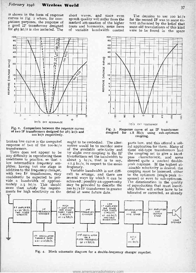
is shown in the form of response curves in Fig. 2 where, for com- parison purposes, the response of a good IF transformer designed for 465 kc / s is also included. The
short waves, and since even speech quality will suffer from the marked attenuation of the higher tones and harmonics, some form of variable bandwidth control
I
80
60 SO .11.1__1.111- ,o MI il
.'"1 J 1
Óf
^ r 30 LIN t0 " Ì
IIIIKI
;I 31 '
1
1
Ó
W INNI
.
¡ I
I 1 ,
1 'IIIIi?l!j t o t kc /s OFF RESONANCE
m
+
Fig. 2. Comparison between the response curves of two IF transformers designed for 465 kc /s and
ioo kc /s respectively.
broken line curve is the computed response of two of the zoo -kc /s transformers.
There does not appear to be any difficulty in reproducing these conditions in practice, so that a low intermediate frequency am- plifier, having but one stage in addition to the frequency changer, with two IF transformers, may confidently be expected to pro- vide a bandwidth of approxi- mately 2.5 kc /s. This should more than satisfy the require- ments for high selectivity on the
T- R F AMPLIFIER
5 -30 MCIS TWO TUNED
CIRCUITS
Ist
FREQUENCY CHANGER
10 OSCILLATOR TUNABLE OVER
6.8 -31.8 MCIS
loo 80
60 50
40 . 30 O
á ce 20 W u o-
O 10
Z 6
á 5 n á la 4
3
2
37
The decision to use ioo kc /s for the second IF was to some ex- tent influenced by the belief that some old transformers of this kind were to be found in the spare
O rv
o 0 o t O O
t
- -¡ CF? CES'):.1KCE
Fig. 3. Response curve of an IF transformer designed for i.8 Mc /s using sub -optimum
coupling.
O Ñ
ought to be embodied. The alter- native would be to sacrifice some of the available selectivity and by slight over -coupling in the IF transformers set the bandwidth to about 5 kc /s, that is to say, ± 2.5 kc /s, in respect to the mean frequency.
Variable bandwidth is not diffi- cult to arrange, and there are several ways by which it can be achieved ; possibly an opportunity may be provided to describe the too kc / s IF transformer in greater detail at some future date.
HIfjH I F AMPLIFIER
ONE STAGE THREE TUNED
CIRCUITS AT I.8 MC /s
2nd FREQUENCY
CHANGER
264 OSCILLATOR ON A
FIXED FREQUENCY OF 1.7 Mc /s
LOW I F AMPLIFIER
ONE STAGE FOUR TUNEO
CIRCUITS AT 100 kc /s
VARIABLE BANDWIDTH
o
parts box, and this offered a use- ful application for them. Many of these old -type transformers had the coupling set to give a band- pass characteristic, and some showed quite a marked double - peak response. If the highest at- tainable selectivity is desired, the coupling must be loosened, either to the optimum (single -peak re- sponse) or even to sub -optimum. The deterioration in the quality of reproduction that must inevit- ably follow will either have to be tolerated or corrected, as already
DEMODULATOR AND
A V C STAGE
BFO AT
lol kc/s
A F AMPLIFIER AND
OUTPUT STAGE
Fig. 4. Block schematic diagram for a double -frequency changer superhet.
V
LOUD SPEAKER
www.americanradiohistory.com

38 Wireless World February 1946
Amateur Communication Receiver - suggested. It is possible, of course, to restore the higher fre- quencies in the AF amplifier by means of a simple form of tone control giving a rising character- istic.
To obtain anything like com- parable selectivity at 465 kc / s
would demand a long chain of transformers giving some ten or more tuned circuits, and these would have to be interspersed with amplifying stages to make good the attenuation of the signal during its passage through the filter.
Availability of an adaptable component largely influenced the choice of the low IF, and it now remains to be seen if an equally convenient peg can be found on which to hang the first, or high, intermediate frequency.
We could commence by elimin- ating the frequencies covered by the tuning ranges in the proposed set, assuming this to be 5 to 3o Mc /s. Likewise the frequen- cies above 3o Mc /s might be dis- missed owing to the difficulty of constructing an oscillator for the
cl FRO1--
RF AMPLIFIER
1RI
second frequency changer having sufficiently good stability at these frequencies. Thus, there now only remain the frequencies below 5 Mc /s.
The link between the high and the low intermediate frequencies is the oscillator of the second fre- quency changer, since its fre- quency must be within ioo kc /s of the first IF. Now it is desir- able that the frequency of this second oscillator be as far re- moved as possible from that of the first, or tunable, oscillator so as to minimise the risk of heterodyning, which could give rise to whistles as well as spurious signals. This then points to the lowest possible frequency for the first IF consistent with adequate second -channel protection.
Any frequency between r and 2 Mc /s should satisfy this condi- tion, that chosen by the writer being 1.8 Mc /s. A satisfactory alternative would be 1.6 Mc /s, and it is quite likely that IF transformers to cover this fre- quency may soon become avail- able, as it appears to be one of the standard frequencies for IF
c6 Re
R10
CI]
13 RI1
amplifiers. The response curve for one of the 1.8 Mc /s IF trans- formers built for a set of this kind is given in Fig. 3.
The block schematic diagram, Fig. 4, shows the functions of the various stages visualised in the proposed receiver. The next step is to translate this into a com- plete theoretical circuit diagram, but this is where paths will in- evitably diverge, for some pro- spective designers may wish to embody waveband switching, ganged tuning and all the refine- ments of the commercial type communication set. Others, less exacting, may be content to com- promise and gang only the signal circuits, thus avoiding the diffi- culties of tracking, but retaining the convenience of waveband switching.
The latter arrangement is well suited to a temporary receiver, since it gives to it a certain flexi- bility should modifications be required, either to the RF ampli- fier or to the oscillator assembly.
With a separately tuned oscilla- tor it is optional whether one fits coils and waveband switching or
a
cv
c
R14 I7
---- =-_-. ` ` \` I
6
C21 IF----- C22 T
d 0 0 a o a ¡o
- ° I2
R6 vv/w---
Fig. 5. Theoretical circuit interpretation of the BFO. Connections for a Colpitts oscillator are inc although they are for the particular valves ment
www.americanradiohistory.com
February 1946 Wireless World
uses plug -in coils. The latter has the advantage that circuits best suited for the different parts of the waveband can be made readily accessible. For example, the Hartley oscillator can be em- ployed for the lower frequency ranges, whilst a Colpitts will usually be more satisfactory for the higher ranges. One method of arranging this is shown in Fig. 5, which theoretical circuit is but one of the several possible inter- pretations of the block schematic diagram in Fig. 4. Here, coil assemblies for both types of oscil- lator circuit, including the Col - pitts, are shown.
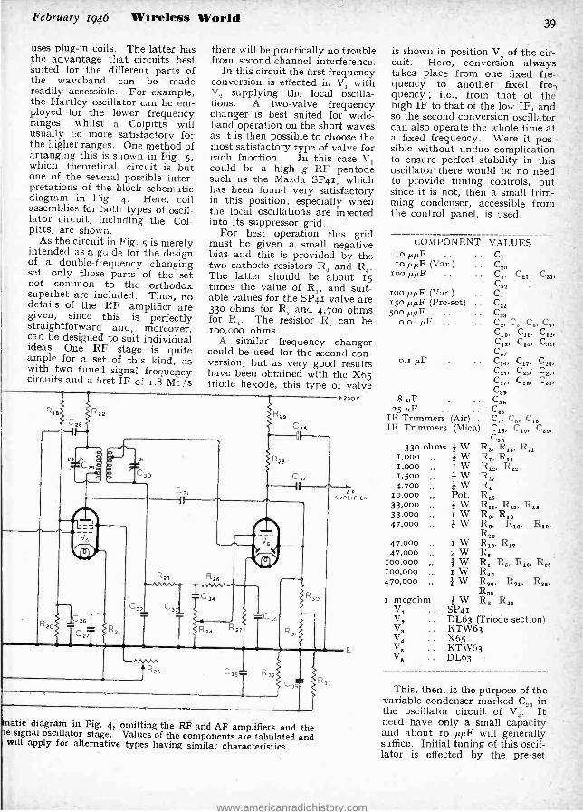
As the circuit in Fig. 5 is merely intended as a guide for the design of a double- frequency changing set, only those parts of the set not common to the orthodox superhet are included. Thus, no details of the RF amplifier are given, since this is perfectly straightforward and, moreover, can be designed to suit individual ideas. One RF stage is quite ample for a set of this kind, as with two tuned signal frequency circuits and a first IF of 1.8 Mo /s
there will be practically no trouble from second -channel interference.
In this circuit the first frequency conversion is effected in V, with V2 supplying the local oscilla- tions. A two -valve frequency changer is best suited for wide - band operation on the short waves as it is then possible to choose the most satisfactory type of valve for each function. In this case V, could be a high g RF pentode such as the Mazda SP4r, which has been found very satisfactory in this position, especially when the local oscillations are injected into its suppressor grid.
For best operation this grid must be given a small negative bias and this is provided by the two cathode resistors R, and R4. The latter should be about 15 times the value of R and suit- able values for the SP4r valve are 33o ohms for R, and 4,700 ohms for R4. The resistor R, can be 1oo,000 ohms.
A similar frequency changer could be used for the second con- version, but as very good results have been obtained with the X65 triode hexode, this type of valve
Ç26
matic diagram in Fig. 4, omitting the RF and AF amplifiers and the e signal oscillator stage. Values of the components are tabulated and will apply for alternative types having similar characteristics.
39
is shown in position V, of the cir- cuit. Here, conversion always takes place from one fixed fre- quency to another fixed fre -, quency ; i.e., from that of the high IF to that of the low IF, and so the second conversion oscillator can also operate the whole time at a fixed frequency. Were it pos- sible without undue complication to ensure perfect stability in this oscillator there would be no need to provide tuning controls, but since it is not, then a small trim- ming condenser, accessible from the control panel, is used.
COMPONENT VALUES Io µµF .. .. C, Io µµF (Var.) ..
ioo µµF .. .. C5, C21, Ctg
10o µµF (Var.) .. 15o µµF (Pre-set) .. C22 500 µµF . . . . Cos
0.01 µF . . . . C2, Cg, C6, Co, C10, C11, C12,
C12, C14, C84, C
C82 C4
Cgi,
0.1 /./F C18, C37, CYO,
C24, CE6; CY6, C87, C96, C68,
Cg6 +2e0v g µF CSe
25 µF Ce6 IF Trimmers (Air) . . C7, Ce, C16 IF Trimmers (Mica) C1e, Cle, C22,
a
F
CB 33o ohms ¡ W R,, Ris, R21
I,000 } W R,, R34 r W R,2, 1122
W W
Pot. ¡W I W ¡W
1,000 1,500 4,700
10,000 33,000 33,000 47,000
R,, R4 Ras Rii, Re,, R22 R9, Rie R9, R10, Rte, Reo
47,000 I W R,,, R,, 47,000 2 W R6
100,000 I W R,, Rs, R16, Res 100,000 I W Ree 470,000 I W R,9, R81, Ree,
Reg I megohm I W R2, R,4
V, .. SP41 V, .. DL63 (Triode section) V, .. KTW63 V4 .. X65 Ve .. KTW63 V6 .. DL63
This, then, is the purpose of the variable condenser marked C29 in the oscillator circuit of V4. It need have only a small capacity and about io µµF will generally suffice. Initial tuning of this oscil- lator is effected by the pre -set
www.americanradiohistory.com
40
Amateur Communication Receiver - condenser C22 which should be an air -dielectric type and be fitted with a slow- motion control, or have some form of reduction drive embodied in it. A fixed ceramic capacitor, in conjunction with a smaller air - dielectric trimmer, would possibly enable the slow - motion drive for C22 to be omitted and might simplify the initial adjustment.
Excessive amplitude of oscilla- tion must be avoided in this stage and the maker's recommendations concerning the optimum peak oscillator volts should be strictly followed.
The only other matter that seems to require explanation is the arrangement of the roo -kc / s inter- mediate- frequency transformers. Very high amplification can so easily be obtained at this fre- quency that it is advisable, if facilities allow, to curtail it by tapping down the anodes and grids of the valves as shown in Fig. 5. A tapping ratio of 3 to 4, measured in terms of turns on the coils, is quite satisfactory, but it is. of course, only applicable in cases where the transformers are constructed especially for this pur- pose.
Where existing transformers are employed the only alternative is to slightly over -bias the valves V., and V5 by assigning higher values than usual to R15 and R21. If V4 is an X65 and V5 a KTW63 then these two resistors can be increased to 470 ohms.
Admittedly the amplification of V5 is controllable by the manual gain control R25, but this also controls the high IF amplifier V3, in which stage a reasonable ampli- fication must be maintained in the interests of a good signal -to -noise ratio. Although V5 is included in the AVC circuit, only about half the control voltage is utilised.
This is a refinement that could be omitted and V5 excluded from the AVC circuits, but unfortun- ately there then remains only V, and the RF amplifier as controlled stages, which would not be en- tirely satisfactory. It would be unwise to include V4 in the AVC chain, since with a combined mixer and oscillator valve varying the characteristics of the hexode section often reflects on the triode and so causes a shift in frequency.
Wireless World February 1946
TELEVISION PSYCHOLOGY Is the Large Screen Essential ?
By PAUL BELLAC (Engineer, Swiss Broadcasting Service)
IT is extremely interesting to follow in the British and American technical periodicals
the debate on the improvements of television reception. This funda- mental problem has a direct and wide effect on the construction of television receivers. The question is : Ought we to keep on building receivers for the direct vision of the image on the screen of the cathode -ray tube, or should we go over to the intricate projection apparatus ?
.It is obvious that viewers are not satisfied with the size of the picture given by pre -war receivers; they insist upon seeing bigger images. For some people, the future of television depends upon the solution of this important question. It is a fact that the present 74in. x loin. picture or even the gin. x rzin. image of the more expensive receivers is quite unsatisfactory. The mind of the viewer cannot free itself from the impression of midgets given by seeing the tiny figures moving on the screen.
On the other hand, many manufacturers take the point of view -which physically is un- questionable-that a small object seen from near appears just ws big as a big one seen at a distance, providing both are observed from the same angle. To the spectator sitting in the back row of a cinema the big projection screen may well appear smaller than the screen of his home receiver. Therefore, the small screens should be sufficient, so far as the home television receiver is concerned.
However, this conclusion does not take into account the physio- psychological problems connected with the human eye which, as far as we know, have never been pointed out yet, though the part they play is an extremely im- portant one.
When looking at a near -by object, the axes of the eyes strongly converge, contrary to their position when looking from a much greater distance. This
convergency is brought about by a special tension of the optic muscles, and gives our conscious- ness the signal " near." Therefore everything we observe from a short distance gives us the impres- sion " near." But we can receive the impression " big " only if we are involuntarily obliged to move our eyes or even our head in order to see the whole of it. The eye constantly sweeps the field of vision and the operating process of the eye combines the whole of the image by means of the impres- sions received. There are many examples of this. For instance, every photographer knows the advantages of enlargements even when they do not reveal new details. The effect of the Tanagra Theatre -in which, through thé action of mirrors, living actors appear as small as dolls -is also based on this physio -psychological principle.
Further, we notice in television a marked discrepancy between the smallness of the image and the intensity of the sound. To see small figures move and to hear them speak or sing with the whole strength of the human voice pro- duces an unpleasant impression. The combination of all these elements makes it desirable to give to the home television set a size approaching that of the home moving pictures. As long as this condition is not fulfilled, the reception of television will never be satisfactory, even when repro- ducing the transmitted image with all its details.
It is evident that there is a future only for the projection television receiver which meets the public's wishes.
BOOK RECEIVED
" Radio Valve Vade Mecum, 1945," by P. H. Brans. A compre- hensive valve data book of British, American and Continental receiving valves (including Russian) . Pub- lished by Algemeene en Technische Boekhandel, Prins Leopoldstr. 28, Antwerp.
www.americanradiohistory.com

February 1946 Wireless World
NEGATIVE FEEDBACK 1. Some of the Awkward Points Explained
SCJCH a lot has already been written about negative feed- back that the thought of
expecting anybody to read much more seems at first mildly revolt- ing. But in spite of all the ex- planations that have been given (no, I would hate to say because of them) I personally have found the subject remarkably confusing. For example, some articles say feed- back reduces hum, while others utter a warning about the in- creased smoothing needed to pre- vent hum when feedback is applied. Then, what is the real difference between " voltage " feedback and " current " feedback ? A cathode follower looks rather like a " cur- rent " feedback circuit, but be- haves in the opposite manner. And when one reads that voltage feedback reduces the internal resistance of the valve, but that this holds good for some purposes but not for others, what does it mean ? Is the resistance reduced or isn't it ? So, in case there are others who are not quite clear about all this, here are some of the shafts of daylight that eventually penetrated my mental gloom.
The general idea of feedback is simple enough (" negative " is understood from now on). Some or all of the output voltage of an amplifier is fed back to the input in such a way as to oppose the in- put voltage, thus reducing the amplification. To prevent the output from falling, then, the input voltage has to be increased, which is a disadvantage. But it is often worth it, because distortion and other unpleasant things are reduced too, and it is generally much easier to organise a higher input voltage than to obtain equal benefits in any other way. In fact, in designing a receiver to include AVC, the output from the detector is often more than is needed as an input to the audio amplifier, and part would have to be thrown away anyhow. So feedback was a discovery like those of manufacturers who suddenly find that what they had to pay men to cart away or stack into
By "CATHODE RAY "
unsightly heaps is a by- product with a good market price.
Although I don't intend to fall back on mathematics in order to dodge saying things plainly in words, I think it is a mistake to fight shy entirely of symbols. So A will hereinafter stand for the voltage amplification obtained without feedback, and B for the fraction of the output voltage fed back. Some writers call these a and ß respectively. The amplifi- cation factor and internal anode resistance of the valve will be µ and ra as usual. RL will indicate
Rt
(40 kIl)
41
Re doesn't come into the signal question at all, because it is short- circuited to alternating currents by a very high -capacitance by -pass. So v0e = vi ; and of course v.= Av00. If vpe is I volt, y0 is zo volts.
Now suppose we feed back 20 per cent. of this output voltage (i.e., 4 volts) ; in other words, we make B = 0.2. In symbols, the voltage fed back is By0 or ABu00. In order to keep the output at its original level, vpe must be kept constant ; so it is necessary to increase vi by the same amount as the voltage fed back, making it V90 + ABv06, or v0C(r + AB).* This, in the present example, is r[r + (2o X 0.2)] = 5volts,which
f
RL o I
(40 kn.) (20 VOLTS)
+ I
(1,5 kn), µ (25)
--------J
ra (lokf:) /.t (25)
(e)
ii (5 VOLTS)
B vó (4 volTs)
(b) Fig. r. Typical example of a simple amplifier stage (a) without negative
feedback, and (b) with zo per cent. feedback.
the load resistance and Re the cathode resistance, if any. And vac will be the signal voltage applied between grid and cathode ;
vi the total signal voltage input ;
and v0 the signal voltage output. They will do to be going on with, I think ; and to make sure that the meanings of these symbols are clear let us take a simple example, illustrated by Fig. 1(a). Assume the valve has a µ of 25 and an ro of ro,000 ohms. The amplification A, is µRL /(RL -1- r0) ; so if RL is, say, 40,000 ohms, A is 20.
result you have of course already arrived at u ithout bothering about formulai, because I chose easy figures. If you count only what is in the dotted box in Fig. i(b), the valve is still giving a gain of 20 ;
but as regards the whole circuit The position at the input is rather like that
of a man with a net salary of f500 a year. If his expenses are f2,000, lus gross pay must be made up to £2,600. Strictly speaking, vi should be vpe (1 -AB), and B should be -B to indicate that it is negative feedback ; but as this article is about negative feedback exclusively it seems a waste of time putting in a minus every time just to be cancelled by another minus, and is one more thing to have to remember if mistakes are not to be made.
www.americanradiohistory.com

42
Negative Feedback - the gain is reduced by negativ feedback to va divided by the new vi ; that is to say zo /5, or 4.
The general formula for the overall gain with feedback (call it A') is quite easily derived in the same way as the above ex- ample was worked out :
A' = vo!vi = Avoc /vpc(I + AB) = A/(i + AB)
So the gain with feedback is equal to the gain without feedback (or the gain inside the dotted line in Fig. I(b)) divided by 1 + AB. If loo per cent. feedback is employed -i.e., all the output voltage is fed back, as in the cathode follower -B is 1 and A' is A /(A -l- I) or slightly less than t, as we saw in the November, 1945, issue when considering the cathode follower.
Now to clear up the little mys- tery about " voltage " feedback and " current " feedback (seeing that in both cases it is voltage that is fed back !). The difference is important, because in one case the valve is made to behave as if its ra were lower and in the other as if it were higher.
Fig. 1(b) is one of the many ways of obtaining voltage feedback. The voltage fed back is a pro- portion of the signal voltage across the load, RL. Fig. 2(a) is the simplest form of current feedback,
OUTPUT
vi
(a)
Wireless World February 1946
voltage proportional to the signal current through the load.
The easiest way of seeing what this difference has got to do with ra is to suppose that the load resistance (say, a loudspeaker) is reduced (by connecting another loudspeaker in parallel). The signal current rises because of the reduced resistance, and the output voltage falls because of the increased " drop " in r0. If the valve is a pentode, in which ra is generally much greater than the load resistance itself, the current is only slightly more than before ; and as it has to divide between the two loads the voltage across them falls by nearly 5o per cent. But if voltage feedback is in use, the voltage fed back falls in the same proportion, and re- leases an equal quantity of vi from its job of neutralising the feedback. There is therefore that much more vi available to increase the output of the valve, thus wiping out most of the fall in signal voltage. The balance between these opposite tendencies leaves the output signal voltage much less reduced than it would have been without feed- back. So one result of voltage feedback is to make the valve behave as if it had a smaller ra, so far as constancy of output with varying load resistance is con- cerned.
vi
(b) Fig. 2. (a) Simplest example of "current " feedback. (b), although
apparently rather similar, is actually a " voltage " feedback circuit.
obtained by forgetting to connect a by -pass condenser across the bias resistor, Rc. Here, again, a voltage is fed back, but it is a
Compare with this the result of reducing the load resistance in Fig. 2(a), where the voltage fed back is that due to the signal
current flowing through Rc, and is nearly proportional to it if Rc is much less than RL. As the signal current is increased (if only slightly) the fed -back voltage increases, entirely at the expense of vo0, which is thus unable to maintain the signal to the valve even at its original level. The tendency for the output current to rise is therefore checked, just as if the valve had a huge ra. For operating loudspeakers this is the last thing one wants, so current feedback is avoided in such cases. In fact, unless stated to the contrary, " feedback " will hereafter mean " voltage feed- back."
If it were not for RL, Fig. 2(a) would be a picture of a cathode follower circuit. The position of RL, however, is the essential thing in deciding what sort of feedback is happening ; and in a cathode follower (Fig. 2b) Rc is RL. So the result is too per cent. voltage feedback.
But what are we to say about Fig. 3 ? This is the " concertina phase -splitter circuit, used in the Wireless World Quality Am- plifier. As it is required to provide two equal outputs it has two load resistances, one of which serves as a current feeder -back for the other and a voltage .feeder -back for itself. So, as it appears to be both sorts of circuit at once, what happens to ra ? Well, it is not like the chameleon in the story, that blew up when it was put on a Scotch tartan ; it does manage to be tw© opposite things at the same time. It all depends on which way you look at it. Output No. I sees a high- resistance valve, because the voltage delivered to it is practically proportional to RI,' (combined with any other load impedances in parallel). Out- put No. 2, on the contrary, is certain the valve has a very low resistance, because its voltage is only slightly affected by altera- tions in the load impedance. If these two were human they would undoubtedly go to war to uphold their sovereign rights to the truth about ra. As they are not, how- ever, they co- operate quite ami- cably and deliver the goods.
All the same, there is obviously something rather queer about a resistance that can have three entirely different values (counting
www.americanradiohistory.com

February 1946 Wireless World 43
the original, proper, ra) at the same time, same place, same cur- rent, and even the same frequency; and this should put one on guard against indiscriminate use of these " apparent resistance " values. The thing to remember -and which Fig. 3 brings out well -is that the apparent ra due to feedback holds good only from the point of view of the load concerned. The valve itself is quite unaware that its own internal affairs are anything out of the usual.
Before investigating the prob- lem of when to use the apparent ra value (let us call it r'a) and when to use the real ra, it would be a good thing to know what r'. is in relation to ra. This in itself is a trap into which surprisingly learned people have sometimes fallen. We have already worked out that the effect of feedback is to divide the gain by 1 + AB. It can be shown (but don't ask me to do it just now) that distor- tion, noise, hum, etc., are, within certain limits, reduced in the same proportion. But the catch is that ra is divided (apparently) by r + µB. With a triode there may not be much difference between A and µ. In the example with which we started this story, A was 4 /5ths of µ. But in a pentode A is likely to be only a small fraction of µ: The result is that ra is reduced (apparently) far more than the gain or the other things mentioned. In fact, a pentode's µ is so large that even if B is only a moderate fraction, µB is much larger than r, so r'a is approximately equal to ra /µB, or r /gaB, gm being the mutual conductance of the valve. The largest possible B (achieved in the cathode follower, for ex- ample) is r ; in which case r'a is very nearly r /g,,,. In a high - conductance valve, ga may be as much as o.ol amps. per volt, making r'a only roo ohms. This for a valve with an ra perhaps getting on for a megohm 1 So it makes rather a difference which value one uses for one's calcula- tions.
So far we have reckoned that voltage feedback makes the valve behave as if it were an imaginary valve with a lower anode resist- ance, as regards its " regulation," i.e., the extent to which the out- put voltage varies due to changes
in the output current drawn (or what is the same thing, changes in load impedance) ; and have called the imaginary valve's internal resistance r'a. To complete our dream picture it is necessary to give it an imaginary µ, too (call it µ'), which is the real µ divided by the same factor as we have used for r'a, namely, r + µB. So the imaginary g,,, is the same
RL2
Fig. 3. This phase -splitter circuit is an interesting and instructive case, so far as apparent valve
resistance is concerned.
as the real one and needs no new symbol. The real valve with feedback, then, can be replaced in imagination, and in calcula- tions, by one with characteristics µ' and r'a each 1 + µB times less than IL and ra. I am not going to waste the Editor's space by copy- ing out a textbook proof of this ;
but let us try it on our original example, Fig. r(b). Here the dividing factor is r + (25 x 0.2), or 6. So µ' is 25/6, or 410 and r'a is 10,000/6, or 1,667. Suppose an input of 5 volts is applied to a valve of these characteristics (without feedback). Then the output, v{µ'RL /(RL + r'a), is (5 X 4i x 40,000) / (40,000 + 1,667) or 20 volts, which is what we have found the real valve with feed- back gives.
Now see what happens to this output voltage when RI, is halved, say, by adding another 40,000 ohms in parallel. The new out- put is (5 X 4j X 20,000)/ (20,000 + 10,000), or 19.2 volts. (Check it by the " real " way if you wish.) Compare this with the drop in volts that would occur
in'the Fig. r (a) circuit ; (I X 25 X 20,000)/(20,000 + ro,000) or 161 volts - a drop of 3.3 volts instead of o.8. It is clear that feedback is a great help in a system where, for example, vary- ing numbers of extension loud- speakers are used. The improve- ment is even more marked with pentodes, which have a much higher ra.
Moving coil loudspeakers have a mechanical resonance usually in the region of 8o c /s. If you give the coil a flick it vibrates several times at that frequency before coming to rest. The same thing is liable to happen whenever a sudden transient in speech or music occurs in whatever pro- gramme it is reproducing ; and the resulting 8o c/s note, though short- lived, is something that doesn't belong to the programme. It is distortion that has found its way in, giving the reproduction a false 8o c/s " coloration " or .
boom. I said " liable to happen," because it will not dó so if the loudspeaker has a comparatively low resistance shunted across it. The reason is that the coil vibra- ting in the powerful magnetic field generates an EMF, just like any other electric motor, and if it has a low resistance across its terminals the resulting current causes a force tending to oppose the motion of the coil. I don't think I need recite the rest of any elementary book on Electricity and Magnetism, and will merely mention that a visual demonstra- tion of precisely the same phen- omenon, called damping, can be obtained by shaking a moving coil milliammeter with and with- out its terminals short- circuited.
The anode -cathode path of the valve, having an AC resistance ra, is virtually across the terminals' of the loudspeaker (though the route may be a devious one, including a transformer, the power supply smoothing condenser and the bias by -pass condenser). So the extent to which this particular form of distortion occurs depends on ra. Or r'a ?
If a loudspeaker, or any other generator forming part of RL, tries to pump current into the anode circuit, and voltage feed- back is in operation, its own EMF is fed -not back, because it didn't come from there -to the
www.americanradiohistory.com

44
Negative Feedback- grid. Suppose that at any par- ticular moment the EMF is of the same polarity as the HT source, increasing the current through the valve. It is therefore fed positively to the grid, which makes the anode current increase more, for a given loudspeaker EMF, than if there had been no feedback. The valve therefore appears to the loudspeaker to have a lower resistance than ra, and -yes, you are right ! -what it appears to be is r'a. [If you complain that the idea of any- thing appearing to a loudspeaker is too much like an IEsop's fable, you will prefer to say that the anode current generated by an EMF e caused by the coil of the loudspeaker vibrating is equal to e /(r'a + Rt.) instead of a /(ra + RL).]
By now the nature of this make - believe resistance may be becoming clearer. What we are doing is using Ohm's Law in a circuit where two EMFs are operating, and calculating the resistance of the circuit by dividing one of the EMFs (generally the smaller one at that) by the current. So, of course, we get a queer answer !
In most cases this procedure would be just as silly as it sounds, but in a feedback circuit there is some method in the madness, because the neglected EMF, wig., is itself rather of the " apparent " variety, and has for some time been the occasion for a lively technical dogfight, which I have no inten- tion of joining. The point is that there is another voltage - the fed -back voltage is real enough, at least -controlling the anode current, and as this voltage is exactly proportional to the original EMF, it is sometimes simpler to consider the results as being due to a lower resistance instead. It is as if a Rich Uncle (this is a Tale of Long Ago) adopted the benevolent practice of contributing half a guinea for every 4s. 6d. saved by young Harry for the purpose of buying Savings Certificates. From young Harry's point of view -and from nobody else's -Savings Certifi- cates would cost 4s. 6d. It would only be reasonable to express the situation in this way so long as Uncle's " EMF " was strictly proportional to Harry's smaller one.
Wireless World February 1946
Incidentally, exactly the same convention is adopted with regard to the apparently enormous input capacitance of a valve due to Miller effect. The large extra capacitance does not really exist at all ; it just appears to do so because we leave out of the account a second and relatively large charging voltage because it happens to be proportional to the input voltage.
Reverting to our loudspeaker damping question, applying the optimum damping resistance is merely a matter of choosing the amount of feedback, B, which makes ra /(I + AB), which is r'a, equal to that resistance. The only problem, then, is to decide what is the optimum. Mr. Amos re- commends something of the order of half the mid- frequency loud- speaker impedance (referred to the primary of the output trans- former) . *
Bearing in mind that r'a is what the valve looks like to the load, the same technique covers other problems in which it is desirable to match the impedance of the signal source to the load. For example, a transmission line. Here the source should be equal to the line impedance, and as that is generally quite low, a cathode follower is almost the only answer.
Do you think this sounds like the end of the valve- and -load story ? That in all such questions it is on r'a, not ra, that the answer is based ? If so, you must not miss the sequel next month.
* Feedback and the Loudspeaker, December, 1044 ksue.
A SIMPLE OHMMETER
IN the July issue of Wireless World a description was given of a
method of measuring resistance by means of a milliammeter and a volt- meter. The writer has been using a similar instrument requiring only one meter, and the following details may be of interest to readers.
The milliammeter Rm has a re- sistance of loo ohms and a full -scale current consumption of i milliamp. A resistance R, equal to the re- sistance of the meter is connected as shown. R, is a wire -wound resist- ance of Io,000 ohms, correct to within ± I per cent. The resistance to be measured, X, is connected to terminals T, and T,.
With the switch down, the meter will be in series with the unknown
resistance X and will measure the current flowing through it ; R, will be in series with R, and will simu- late a voltmeter load. If the switch is thrown up the meter becomes a voltmeter reading o -so volts. The voltage indicated will be that across X and R,. As R, is equal to Rm it will compensate for the removal of Rm from the circuit ; in other words, the voltage now indicated is that across X and Rm when the switch was down. Strictly speaking, R, should be 9,90o ohms to take into account R.= loo ohms, but the error will be very small.
The following ranges of resistances can be measured: -(I) With the switch down : -Vary R, to such a value that the milliammeter indi- cates o.ImA. Then throw the switch up and read the voltage. Then from Ohm's Law we get -
Volts Resistance X = ohms
o.000r In other words, the resistance
equals the voltage multiplied by Io,000. For example, a reading of 6.3 volts means that X = 63,000 ohms. The maximum resistance which can be measured on this range is Ioo,000 ohms, corresponding to a reading of ro volts.
With R, adjusted to give a cur- rent of I.o milliamp., on throwing the switch up the voltage is read, and we get :-
Volts X _ ohms
0.00I
or, the resistance equals voltage multiplied by I,000. The maximum resistance which can be measured on this range is Io,000 ohms.
B
12 VOLTS
3
10 il f Q
T, X T2
The meter is switched for successive current and voltage readings with- out altering the load on the battery.
It should be clear that in each case the resistance of Rm (loo ohms) should be subtracted from the resistance obtained above, but in most cases, however, Rm can be neglected. " CALIBRATOR."
R,., R2 loo C2© oofl
www.americanradiohistory.com
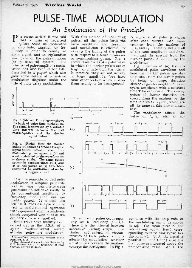
February 1946 Wireless World 45
PULSE -TIME MODULATION An Explanation of the Principle
IN a recent article' it was said that a train of recurrent pulses could be modulated
in amplitude, duration or fre- quency in order to convey an audio signal, and an explanation was given of the pulse- duration (or pulse- width) system. The principle of pulse -amplitude modu- lation has also been rather fully described in a paper2 which also gave some details of pulse -time modulation disguised under the title of pulse -delay modulation.
f <
T
With this method of modulating pulses, all the pulses have the same amplitude and duration, and modulation is effected by varying the timing of the pulses with respect to a series of marker or synchronising pulses. Fig. s shows three cycles of a pulse wave in which the marker pulses are of larger amplitude than the others. In practice, they are not usually of larger amplitude, but have some other feature which enables them readily to be distinguished.
t,! t3-.! Fig. I (Above) This diagram shows the basis of pulse -time modulation. The signal is conveyed by a variable time interval between the tall marker -pulses and the shorter
signal pulses.
Fig. 2. (Right) Here the marker pulses are shown as broader than the signal pulses instead of taller. Un- modulated pulses appear at (a) and a set modulated by the waveform (e) is shown at (b). The same pulses appear in opposite phase at (d) and at (e) the pulses of (b) have been converted to width -modulation by
a trigger circuit.
It will be remembered that pulse modulation is adopted primarily because most centimetre -wave generators do not take kindly to the conventional amplitude or frequency modulation but are readily pulsed. It is used also because it lends itself particularly well to multi- channel operation with equipment which is relatively simple compared with that of the ordinary sub -carrier method.
Some trials have recently been carried out in the U.S.A. of a 25 -cm. twelve- channel system utilising pulse -time modulation.
1 Pulse -Width Modulation, Wireless World, December, 1941.
Multi -Channel Communication Systems, by F. F. Roberts and J. C. Simmonds, Wireless Engineer, November, 1945
TIME
(a)
(b)
(c)
(d)
(e)
ta single small pulse is shown after each marker with time - spacings from the markers of ,, t2 and t3. These pulses are all
of the same amplitude and dura- tion, and the spacing from the marker pulses is varied by the modulation.
Fig. 2 shows at (a) the un- modulated pulse waveform and here the marker pulses are dis- tinguished from the carrier pulses by being of longer duration instead of greater amplitude. Four cycles are shown with a constant time T for each cycle. The carrier pulses of shorter duration are spaced from the markers by the time intervals t,, t2, etc., which are all the same in this unmodulated case.
The modulation affects the value of t1, te, etc., in ac-
t '- t t'- 1
i4 T T
-T{ µ- t4 I
t I t2 I
s t3 I ln n r -xy) G+ x--y x 1-.-y--
r--t4--1 _ n ,
T .aI
A
C
F-I a-----x--
G.-y-{x- y{-{ --y-){{ I t' I t2 t3 I t4 I
These marker pulses occur regu- larly at a frequency f = r/T where T is the interval between successive leading edges. The timing, and indeed all charac- teristics of these pulses, are un- affected by modulation. Another set of pulses between the markers conveys the intelligence. In Fig. r
cordance with the amplitude of the modulating signal as shown in (b). The small piece of the modulating signal itself corre- sponding to these four cycles has the form (c). At A, the signal is positive and the timing t, of the first pulse is increased above the unmodulated value. At B the
, 4i
www.americanradiohistory.com

46 Wireless World February 1946
Pulse -time Modulation - signal is still positive but not to such a great extent, so that the second pulse interval t2 is less than t1, but still above the unmodu- lated value.
The signal at C is passing through zero, so that the timing of the corresponding pulse is unaffected. At D the signal is negative and consequently t4 is less than the unmodulated value.
In the case of a single -channel system the difference between pulse -time and pulse -width modu- lation is not large. If the wave- form (b) is drawn inverted as at (d) it will be clear that the intervals between the end of a marker pulse and the start of the carrier pulse in (b) becomes a set of width- modulated pulses in (d). The further intervals in (b)
between the ends of the camer pulses and the beginnings of the markers, becomes a further set of width -modulated pulses in (d).
The first set of intervals in (b) is designated by x and if the corresponding pulses in (d) are regarded alone, it is clear that they form a duration -modulated series with constant leading edges. Similarly the second set of in- tervals in (b) is labelled y, and regarding the y- pulses in (d) alone, these also plainly form a width -modulated series, but this time with constant trailing edges,
Demodu!ation
Now it was explained previously1 that a width- modulated set of pulses is equivalent to the modu- lating frequency plus the spectrum of the pulse waveform and certain modulation products, and that to reproduce the original modulating waveform it is only necessary to filter out the unwanted frequencies. The waveform of Fig. 2 (d), ar d this is only the signal of (b) in opposite phase, shows two width - modulated sets of pulses. The two sets of pulses, however, are modulated in opposite phase and to the same degree. Inspection of (d) makes this clear, for if an x -pulse decreases in width by any amount the following y -rulse in- creases in width by the same amount.
If the waveforms of (b) or (d) are passed through a low -pass filter, the x- pulses will produce
the original modulating . signal and the y- pulses will also produce it but in opposite phase. The two cancel and the resulting output is zero. The pulse -time modulated signal, therefore, can- not give the original modulating signal merely by a simple filter.
One method of obtaining the audio signal is with a trigger
these the pulses themselves are shown by solid lines and the limits of the pulse excursion by the dotted lines. Under the influence of the modulating signal the pulse can move anywhere within the limits of the dotted rectangle.
The three sets of channel pulses and the marker pulses are added
F
i n-- ;
-, F- if
tb C
at td
Fig 3. A three -channel pulse -time modulation system is illustrated here. The marker pulses are shown at (a) and three individual channels at (b),
(e) and (d). The combined waveform appears at (e).
circuit. It is not hard to devise a valve circuit having the property of changing from one fixed output to another each time a pulse is applied. Thus, the anode voltage of a valve might change between two fixed values of too volts and Zoo volts. If originally at loo volts it would jump to Zoo volts on the application of a pulse and stay there until the next pulse makes it return to too volts, and so on.
Such a device applied to the waveform of Fig. 2 (b) would produce an output (e). This is a single set of width -modulated pulses and the audio signal can now be produced by .passing it through a low -pass filter.
Multi- channel operation can be obtained by interlacing sets of staggered pulses, for it is only the changes in the pulse timing which convey the modulation. A common set of marker pulses can be used for each channel. Three such channels are shown in Fig. 3. The marker waveform is at (a) and the three sets of channel pulses at (b), (c) and (d). On
together at (e) and give the com- plete pulse waveform. The varia- tions of timing tb give the signal corresponding to channel b, the variations of timing t, that corre- sponding to channel c and so on. At the receiving end, the channels are first separated by a gating device, which is triggered by the marker pulses, and then de- modulated individually.
VACUUM -SEAL BUSHING
ATECHNICAL leaflet describing Ferranti's Type 625Bí -bushing
gives dimensions and methods of application. The insulator is a
hollow truncated glass cone (-W- A ") with copper flange and end cap for soft soldering to metal case and lead -out wire. If desired, the insu- lator can be inverted and mounted inside the case, when the cone can be used to give support to a flexible lead ; the live connection is then completely protected and the com- ponent can be handled with safety.
Under normal conditions maxi- mum working potentials up to r,000 volts can be employed.
The leaflet is obtainable from Ferranti, Ltd., Hollinwood, Lancs.
www.americanradiohistory.com

February 1946 Wireless World 47
INSTRUMENT PROGRESS: 19391946 Reflections on the Physical Society's Exhibition
NOTT least among the marvels the Physical Society's
Thirtieth Exhibition was the catalogue. It was a- novel ex- perience in these days to see such good value for money ; but to get a much greater quantity of paper -and good paper at that - than in 1939 surely this raised the whole affair to the plane of the miraculous at the very start. A grateful tribute must be paid to those who, under great diffi- culties, compiled this valuable work of reference ; and to the Paper Controller for what we hope is but a sample of a more en- lightened attitude to scientific and technical needs.
Whether the Exhibition itself fulfilled expectations, pitched peak -high by its being six war years instead of one peace year since the last, depended on how closely one had been in touch during that interval. Even the visitors who were not inside some part of the veil of secrecy during the war had opportunities in the last few months of reading about the more spectacular develop- ments, and for them the edge must have been dulled. But to any Rip van Winkle coming in fresh from 1939 the atomic bomb itself would have been less un- expected than the magnetron, weighing a mere pound or so, but capable of generating 500 kilo- watts at 3,000 megacycles per second, via a single -turn coupling coil only tin. in diameter. He would have been impressed -to put it gently- with this example of the way in which a one- hundredfold extension of radio frequency had been exploited. The whole centimetre technique, col- loquially called plumbing, to him would have been new and strange. Perhaps the most significant fact about it all is that, instead of a few scientists playing around in laboratories with elusive milli - watts, many mechanics have been handling real power in a most practical manner in the field.
For another of the outstanding changes is that, instead of the per-
By M. G. SCROGGIE, B.Sc., A.M.I.E.E.
functory " tropical finish " of pre- war days, apparatus of greater and greater complexity and pre- cision has had to be made so that it can go from stratospheric cold to steaming heat, be dropped in the sea, blown up, installed in termite's nests, fired from guns, and still work. This experience should be all to the good in tack- ling one of the biggest peacetime problems -the export trade.
Another war influence that should be seen in future products is the so -called miniaturization. Very small valves and com- ponents used to be too " special." Now they have had to be mass produced.
Looking at the Exhibition more particularly for its measur- ing and test gear, two things (both traceable to the war) struck one, In the old days, it was assumed that most of the in- struments shown would be used, if not by scientists, at least by " persons skilled in the art." Now, not only is the tendency to make them as foolproof as pos- sible, but many exhibits had no other purpose than to enable skilled operations to be carried out by unskilled persons. An ex- ample outside our field, but mak- ing use of its technique, was the large variety of " magic eye " instruments for indicating the end -point in chemical titration. The emphasis of the Exhibition, in fact, was far more on in- dustrial needs than ever before.
The other notable feature was that the instruments, with some exceptions, were more specialised. There were fewer " do-alls " and
pocket laboratories." One notable exception was the AVO Multi - Range Electronic Test - meter. Its specification is one of the things that would have wakened Rip van Winkle with a start. The applicability of many of the other AVO instru- ments has been widened by
accessories, so that - another " industrial " touch - our old friend the Avometer can now measure up to 48o amps. Another versatile new instrument was the Labgear Fault Tracer, With one of these miniature cathode -ray oscilloscopes and an AVO r,000 ohms -per -volt AC /DC test meter, there are few service jobs that could not be tackled.
A significant trend was seen in the Cossor Type 448 oscilloscope, which might well be called an " oscillometer," for its controls are directly calibrated in time and voltage, and facilitate quanti- tative study of waveforms.
While progress has gone ahead in so many directions, none has been made towards dropping the absurd term ' ` DC current," which was more prevalent than ever. But while terminology was unregulated, the same could not be said of power supplies. The ubiquity of equipment de- signed to counteract fluctuations in mains voltage was no compli- ment to supply authorities. Con- stancy of voltage with change of load was also well provided for.
Among many other signs of progress, the following are stray samples : 0.012 farad capacitors (TCC) ; roo,000 ohms - per - volt moving -coil multi-range meters (Tinsley) ; ohmmeters reading to 5,000,000 megohms (British Physical Laboratories) ; oscillo- graph sensitivity of 0.005 volts / cm. from z c / s to z Mc / s (Mul- lard) ; and 40 Mc /s quartz crystals (Marconi). And if one found all these things rather tire- some, one had the opportunity of learning how to measure the radius of curvature of razor blade edges, the turbidity of beer, and the firmness of cheese (con- sidered as a highly viscous New- tonian fluid or an approximately Hookean solid). One of the great values of this annual Exhibition, in fact, is that it helps to broaden the outlook by revealing the ways in which progress in so many sciences and industries is in- creasingly inter -related.
www.americanradiohistory.com

48 Wireless World February 1946
PHYSICAL SOCIETY'S EXHIBITION
EQUIPMENT for test, measure- ment and research still forms the backbone of the Physical
Society's Exhibition, but, perhaps to a greater extent than in pre -war years, new materials and accessories intended for more general use were exhibited. At the Exhibition, held in London on January Ist -3rd, radio was well to the fore ; hardly a stand, except perhaps in the optical section, failed to show something of a radio or radio -like nature.
Meters of the type which may be described as pointer instruments cover a very wide field as they form the nucleus of all multi -range test sets and figure in one form or another in most test instruments. Meters of this kind were shown by many firms, including British Physical Laboratories, Elliott,
First Post -war Show of Testing and Measuring Gear
AVO valve tester incorporating an overload cut -out
Measuring Instru- ments (Pullin), Sangamo - Weston and Ernest Turner.
A n interesting development was seen in the AVO instruments i n which there is em- bodied an overload cut -out which not only protects the delicate movement
of the meter, but now safeguards the instrument as a whole. Among the new Avometers is a multi -range meter similar to the earlier standard type but fitted with a high - sensitivity movement requiring only 5op.A for a full scale deflection. This gives a resistance on the DC voltage ranges of 20,000 ohms per volt.
Dynamometer instruments in two - and three -element types were shown by Sangamo -Weston. These are doubly magnetically shielded and have an accuracy of from 0. r per cent. to 0.25 per cent.
Measuring Instruments (Pullin) were showing a meter with scales engraved for multi -range use, but without shunts, series resistances and other adjuncts. This is for use as the nucleus of a comprehensive test set for which the firm can
Coil Analyser made by Eritish Physical Laboratories
supply circuit values and other data.
Test Equipment. -There was a wide range of factory production test equipment and radio servicing apparatus, among which the new Model rs AVO valve tester was con- spicuous. This is a very flexible in- strument enabling every practical test to be carried out on all normal type valves in general use. It pro- vides for measuring mutual con- ductance, reads current to all elec- trodes and voltage to the majority, and enables a complete set of valve characteristic curves to be plotted. Inter -electrode insulation can also be measured. The AVO safety cut -out already mentioned is included.
British Physical Laboratories have developed a range of test sets cover- ing the requirements for production - line testing of radio equipment. These include a high- frequency capacitance bridge for measuring capacitors of from rpF to 3,000 pF at xMc /s, an electrolytic condenser bridge covering capacitors of o.2µF to 22ooLF and fitted with an auto- matic overload protection device, various ohm and megohm meters .
and a comprehensive coil analyser giving " Q " values and the self - capacity of coils from direct -reading scales. It covers a range of induct- ances from o.8iH to ioomH and " Q " values between so and 500. A coil comparator designed for rapid testing and adjustment of coils under mass- production conditions was also shown.
A " Q " meter for measurements of coils, condensers, aerial equip-
Leland VHF "Q " meter
www.americanradiohistory.com

February 1946 Wireless World
ment and dielectrics at the unusually wide frequency range of 3o to 2ooMc /s was shown by Leland In- struments. Described as the Boon- ton Model 170A it covers a range of " Q " values of o -300 by direct reading, which is extended to 1200 by a multiplier.
Made by the same firm is a series of combined frequency and ampli-
be used for modulation. Ganged to the frequency control are the tuned circuits of a built -in receiver which can be used to detect a signal in the early stages of a set and so enables each stage to be tested indepen- dently. A resistance- capacitance bridge is also included.
Resistance -capacitance oscillators were to be found on the stands of
many firms. Dawe Instruments have two models, one covering toc /s to 2okc /s with an output of r watt and another cover- ing toc /s to zookc /s, but with only roomW out- put. Marconi In- struments have one covering 15- 20kc /s in three ranges with out- puts of 5o volts in 5kfl or ro volts in 600fl for 0.4 per cent. distortion.
tude -modulated signal generators. The standard model 150A provides a signal voltage in two frequency bands, a carrier frequency variable between 41 and 5oMc /s and an inter- mediate frequency covering 1 to xoMc /s. Either AM or FM can be used on either radio -frequency band. Other models in the series provide different frequency ranges.
The television test oscillator shown by E. K. Cole provides a standard signal pattern for checking and adjusting television receivers. It is normally connected by cable to the set, but a short aerial rod may be used to give a feeble radiated test signal.
A versatile resistance -capacitance bridge embodying a valve -voltmeter was shown by Measuring Instru- ments (Pullin) . Apart from measurements against built -in stan- dards the bridge can be employed 'with external standards and as a valve -voltmeter. The resistance range is in to roMfl and the capaci- tance coverage is ropF to roop,F.
An interesting piece of apparatus is the Labgear Fault Tracer. This consists of a signal generator cover- ing iookc /s to 3oMc /s with a 1,000 -c /s AF Oscillator which can
(A b o v e) Pullin resistance - capa- citance bridge embodying a valve -voltmeter
(Right) The Labgear Fault
Tracer
49
Pulse or sine -wave modulation is provided.
The Mullard BFO Type E8io has 4 watts output for r per cent. dis- tortion and the output is constant within rdb. from r5c /s to 2okc /s. Impedances of 15,600 and 2,500û are provided.
The electronic frequency meter shown by Salford Electrical Instru- ments has a range of 5oc/s to 45 kc /s and is independent of wave- form. The frequency to be measured is first converted to a square waveform of constant volt- age and then applied to a rectifier stage in which the indicating instru- ment shows a deflection propor- tional to frequency.
Two interesting high -voltage valve voltmeters were shown by Sal- ford. One makes use of the lineal, relationship which exists between grid and anode voltages in a cathode -ray tube at the point of ex- tinction of the beam. The voltage to be measured is applied to the anode and the extinction voltage is read off a calibrated grid bias con-
This firm had also a I oscillator; it is a BFO with outputs from 5oc /s to 5Mc /s in two bands. The output is r watt into impedances from 2011 to 1,00011.
A feature of the Marconi Instru- ments TF867 signal generator, which covers r5kc /s to 3oMc /s is an AGC system to keep the output constant within ± idb. without re- setting. There is a manual adjust- ment for precise setting as well, and a crystal calibrator is included. The TF8or covers 6- 300Mc /s in four bands with turret coil- changing; there are no switch contacts, the coil connections being made through the capacitance of vanes attached to each coil meshing with fixed vanes.
trol. Peak voltages up to io,000V may be measured and the instru- ment is suitable for audio or radio frequencies and pulses. The other, incorporating a capacitance poten- tial divider, has been developed for the plastics industry for measuring potentials up to ro,000V in RF heating equipment.
Impedance measurements are catered for in several ways. Dawe Instruments have a T- bridge for in- ductances between romH and rooH, the measurement being made at Loomis and also an impedance comparator covering zoµH to roomH, zopF to o.rµF and 4011 to rookll. An impedance meter of the " ohmmeter " type was shown by
www.americanradiohistory.com
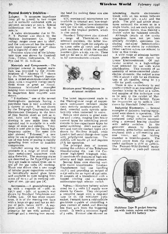
50
Physical Society's Exhibition - Labg.ar. It measures impedance from 30 to 5,000fû in two ranges and is normally calibrated with ro per cent. accuracy at 5oc / s. Special calibrations can be made up to zokc/ S.
A valve electrometer due to Dr. F. T. Farmer was shown by the Baldwin Instrument Co. Three voltage ranges cover zero to 28oV, and the instrument has the remark- able input impedance of zo18 ohms and a capacity of only zpF.
Precision apparatus of the labora- tory type was shown by Gambrell Bros., Clifton Instruments, W. G. Pye and W. H. Sullivan.
Materials and Components. -The principal interest in magnet mate- rials was provided by the demon- strations of " Alcomax II," shown by the Permanent Magnet Associa- tion, a nickel -aluminium- cobalt -iron alloy, with a magnetic energy nearly three times as great as Alnico. Numerous fabricated examples ranging from miniature pick -up bars to magnetron field magnets were shown.
" Telcothene," one of the newest thermoplastic materials having a polythene base is now available in a variety of styles. It was shown by the Telegraph Construction and Maintenance Company in the form of thin flexible sheet as well as in rod, tube and strip. Insulating sleeving is now made from this material and is available in a wide range of sizes and colours. Telco - thene is used also in the Telcon high frequency cables. The same firm alsd showed " Telcoseal," a new alloy for use in glass -metal seals ; the use of this form of sealing is rapidly spreading from valves to humbler components.
Included among the latest TCC products is a range of small disc - type metal -cased capacitors with mica dielectric. The receiving styles are described as the Type CM3o and they are made in values from zoo to 50o pF for 35o volts DC working. There was shown also a new range of tubular paper capacitors enclosed in hermetically sealed glass tubes and available in sizes ranging from o.00x µF to o. z µF in working volt- ages of 200, 350 and 500 DC.
Accessories. -A gramophone pick- up with a response of -2db. at 25c /s and -5db. at 9,000c /s was shown by Standard Telephones and Cables, Ltd. Of boo ohms imped- ance, it is of the moving -iron type with a large air -gap and has an out- put of 3odb. below rmW. A sap- phire needle is used. It is designed primarily for use with acetate re- cordings and a moving -iron record-
Wireless World
ing head for making these was also shown.
STC moving -coil microphones are available in tropical and non- tropi- cal types. The latter have aluminium wire for the coil, whereas copper is used in the tropical pattern, which is also sealed.
Standard Telephones also showed a range of Thermistors ; also selenium rectifiers, the latter low - current tubular types for outputs up to 2,000 volts at zomA and single plate rectifiers of which the smallest is some o.55in. x o.2in. x o. 'in. These last are for use in AC voltmeters and in AF communication circuits.
Moisture -proof Westinghouse in- strument rectifiers
The latest improvement made in the Westinghouse range of copper - oxide instrument rectifiers render them entirely moisture -proof. In- deed, unsealed units operate satis- factorily when immersed in water.
Relays were shown in great num- ber and variety, ranging from heavy current types for controlling power circuits to low- capacitance types for aerial switching. Both normal pat- tern and mercury- contact types were shown by Hendrey Relays, while Londex had aerial change -over types with polystyrene insulation. The AECO4 will handle 4A and requires 3VA for operation.
The principal item of interest among the exhibits of the Telephone Manufacturing Co. was the Car- penter high -speed telegraph relay. It combines the features of high sen- sitivity and high contact pressure.
Several firms were showing vari- able mains transformers. Gresham Transformers had one handling iokVA and providing an output of o -23o volts for an input of 23o volts. It consists of a transformer with a tapped winding and a separate commutator -type selector switch.
Valves.- Miniature battery' valves rated for 1.4 volts LT supply were shown by Cossor. They comprised a complete range with a ring -seal base to fit the miniature 7 -pin socket. Ferranti have a cold- cathode gas -triode capable of controlling a peak current of 2omA and drawing less than 4µA from the triggering circuit. It needs a minimum signal of 5 volts. Ferranti also showed an
February 1946
interesting double electrometer triode with an ion screen between the filament (2V, o.zA) and the grids. The grid and anode struc- tures surround the screen as in a single triode, but are each split into two separate halves, thus making a double valve for balanced circuits.
Although details of the cavity magnetron have not yet been officially divulged, specimens (in- cluding cut -away demonstration models) were shown by exhibitors. Other wartime valves are referred to later in this review.
A wide range of selenium barrier - layer photo -cells was shown by Evans Electroselenium. Of par- ticular interest is a high -voltage type intended for use with valve amplification. This consists of an assembly of series -connected photo- electric elements ; the output across OM is about r volt for an illumina- tion of 5ft.- candles, rising to 7.3 volts for 5ooft.- candles.
There is now a tendency to seal quartz crystals in an evacuated glass envelope similar to that of a valve, and samples of this technique were to be seen in the exhibit of Mar - coni's W.T. Co. and Salford. Types for frequencies up to roMc /s were shown by Standard Telephones.
Industrial Electronics. - Several examples of dielectric heating equip- ment were shown in operation. The trend of design is towards self - contained metal cubicles incorpor- ating a screened heating chamber with safety switches. In the generator shown by Scientific Acoustics, press -button controls are employed with a self- resetting pro- cess timer, and the heating chamber is interchangeable. The output power from the single air - cooled oscillator is 2kW at 45Mc /s. The Ferranti -Wild -Barfield equip- ment employs a push -pull circuit
Multitone Type B pocket hearing aid with 'comm. valves and layer -
built HT battery
www.americanradiohistory.com

February 1946 Wireless World 51-
giving 2kW at 35Mc /s, and an in- teresting feature is the automatic power output control in which the spacing of the " work " electrodes is varied by a small motor. Demon- strations were given by Rediffusion of their RH2 generator working in conjunction with apparatus for dry- ing powders and the rapid concen- tration of temperature -sensitive chemical solutions.
The application of valve voltmeter methods in conjunction with a " magic eye " indicator has simpli-
plied to a reversing motor which moves the potentiometer slider to- wards the new balance point.
Grain moisture measuring equip- ment was shown by many organisa- tions, and usually functions by measuring the capacitance of a stan- dard quantity of grain. The NPL showed the circuit of a simple AC- operated meter in which an alter- nating voltage is applied through a phase- shifting network to the grain cell. The output is compared with the phase of the supply in a valve
circuit. The Mar- c o n i Instruments models -both bat- tery and mains driven - measure the effect of the grain cell upon the
Q " of a circuit, and means are pro- vided for ensuring that the cell always contains
fled potentiometric titration end- point measurements which can now be carried out by junior laboratory assistants. Examples shown were the Griffin and Tatlock " Tep- meter " and the Mullard -BTL potentiometric titration apparatus. These operate from AC mains, and the EMF developed by suitable elec- trodes in the test solution is balanced against a calibrated potentiometer.
Several methods are employed for the detection of cracks in metals. In the Salford crack detector the prin- ciple involved is the change in fre- quency of a tuned circuit Paused by interruption of the surface eddy currents in the specimen. The super- sonic flaw detector shown by Henry Hughes works on the echo sounding principle, 2.5Mc /s quartz crystals being used as surface transmitters and receivers. A pulse technique is employed in conjunction with a CR tube display, and indications of cracks, porosity and other faults are given up to depths of raft. with accurate information of the distance below the surface.
Another application of valves was seen in the Honeywell -Brown elec- tronic continuous balance potentio- meter pyrometer. In this the un- balanced voltage is amplified and converted to AC which is then ap-
Above) Cossor Model 448 double -beam os-
cilloscope
(Right) Marconi Instruments Electrostatic
Viewing Unit
Electric. Those who are unable or unwilling to take advantage of the system of " unmasked hearing " which requires the use of separate earpieces are now offered the alternative of " differential com- pression " for which only one ear- piece is necessary. Amplitude com- pression is applied in the middle and low frequencies but not to the high frequencies; thus the masking effect of sounds in the regions of highest energy is reduced and intelligibility improved. A range of new pocket aids employing British -made romm. valves and -layer-built batteries was shown. The Type B measures only 5Iin. x 2j(in. X r }in. with self -con- tained batteries and weighs 12k oz. The LT consumption is only 6omA at 1.5 volts. Instruments for re- search in hearing deficiencies and permanent hearing aid installations for schools for the deaf were also exhibited.
The portable Cambridge electro-
the standard quantity of grain. The Mallard instrument measures the capacitance change and covers the ranges of II -30 per cent. mois- ture content for wheat, ro -25 per cent. for oats, and 12 -25 per cent. for barley. The Dawe Instruments model functions by measuring the alternating current passed by a stan- dard quantity of grain, and this same principle is also applied for ascertaining moisture content of timber.
Marconi Instruments showed a pH meter employing an electrometer triode with an HT supply stabilised by a thyratron. It is AC operated and the warming -up drift does not exceed 15 minutes.
Medical Applications. -Many new developments in hearing aids, both in principle and practice, were to be found on the stand of Multitone
cardiograph makes use of a string galvanometer, projection lamp and continuous paper camera and measures only loin. X rljsin. x 9in.
Cathode -ray Gear. -The cathode - ray oscilloscope has now been with us for many years, but is steadily being improved, particularly in its accuracy for quantitative work as distinct from its use as a pictorial wave indicator. The Model 448 double -beam oscilloscope shown by Cossor has a tube giving a par- ticularly fine trace ; the time -base can be used to give a single stroke triggered by the input wave as well as to provide a repetitive scan syn- chronised by the input. The amplifier has a gain control which operates by varying negative feed- back and at low gain its response extends from 5oc /s to 5Mc /s. An amplifude scale calibrated in volt-
www.americanradiohistory.com

52
Physical Society's Exhibition - age is provided, and a camera attachment is available.
Mullard had two oscilloscopes, one for low and the other for high frequencies. The former, Type ESoo, includes an amplifier flat within 2db. from o.ic /s to 4okc /s and gives a deflection sensitivity of icm. per mV RMS. The time -base has a range of o.25c /s to I6kc /s. The other oscilloscope is the E8o5, and has an amplifier flat within 3db. from 2c /s to 2Mc /s and is
usable up to 5Mc /s. The sensitivity is 5mV per cm. and the time -base range is 5c /s to I5okc /s.
The Electrostatic Viewing Unit shown by Marconi Instruments is
specially designed for pulse work and includes a time calibration system in which known time in- tervals are obtained by a ringing circuit.
An electron microscope with a resolving power some fifty times greater than that of the best optical instrument, and capable of a mag- nification up to 50,000 times, was shown by Metropolitan Vickers. This is the latest model, the Type EM2, and it operates at 5okV.
VHF Equipment. -A joint exhi- bit of the Research Staffs of the M.O. Valve Co. and General Elec- tric contained some interesting developments of modern VHF tech- nique. Various types of oscillators using line and cavity resonators were shown, including also some
Prototype for new television valves by M.O. Valve Co.
examples of the latest type of butterfly circuit. One such push - pull oscillator fitted with the new disc -seal valves, Type CV273, and incorporating a standard split - stator condenser of the butterfly pattern, had a frequency range of 25o to gooMc /s.
Wireless World February 1946
The many applications that have been found for VHF, and especially for the centimetric waves, is re- flected in the latest Marconi -Osram valves. These include magnetrons and the new disc -seal triodes.
In the latter the cathode, grid and anode electrodes take the form of copper discs extending beyond the normal diameter of the glass enve- lope and connection is made by ex- ternal bands clamped to these discs.
With this form of construction the inductance of the internal con- nections to the electrodes is reduced .
to a minimum and the valves are suitable for use at very high fre- quencies. For example, the CV273 triode will oscillate up to 3,50o Mc / s and it is designed for insertion into the end of a concentric line.
Some new 8 -pin pressed glass base valves, which are suitable for the television frequencies, were shown in prototype form and a complete range covering all requirements is expected to emerge shortly.
The NPL was showing a wave - meter covering Soo- Io,000Mc /s using a cavity resonating in a hybrid TM.,.-coaxial mode with a non - contact plunger. A crystal de- tector is incorporated and the ac- curacy is I part in to`. A similar wavemeter to NPL design was shown by Standard Telephones. This firm also showed several centi- metre -wave signal generators. One model covers 7.I -IIcm, using a velocity- modulated valve in a wave - guide. The frequency control operates, by means of a micro- meter -head, a piston moving in a cavity resonator.
High- frequency and centimetre - wave cables with polyethylene di- electric were shown by British In- sulated Callender's Cables, and on this same stand were to be found a number of flexible waveguides. In one of these metal discs are spaced in a rubber hose so that the gaps form resonant cavities to give an effectively continuous structure at the operating frequency.
Miscellaneous Exhibits. -Voltage stabilisation and regulating devices are important ancillaries in many laboratory, industrial and production testing equipment. Apparatus of this kind was shown by the Zenith Electric Co. in the form of motor - controlled and manual- operated variable voltage transformers.
Westinghouse also include among their products a range of constant potential AC voltage units giving an output of good waveform and de- scribed as " Stabilistors." 'They include no moving parts.
The Cossor Dot -Mosaic Scanner is designed for testing the linearity of CR tubes with electric deflection. The scan voltages are derived in
accurate small steps from wire - wound potentiometers, the tapping points being selected by mechanical selector switches to produce a series of accurately spaced dots.
Ilford were showing a wide range of paper and film specially designed for photographing cathode -ray traces. One blue- sensitivity type
BI Callenders flexible waveguide
can cover a range of writing speeds of to`: r and can be completely pro- cessed in 3o sec.
Among the vacuum thermo -junc- tions shown by the Cambridge In- strument Co. were a range of centi- metre dipole types with the aerial electrodes fused directly into the sides of the glass bulb. Thermo- couples designed for building into the walls of resonators and wave - guides for monitoring purposes were shown by Standard Telephones. They are designed for frequencies of 300- 6,000Mc /s with a maximum current of 15mA.
In the " ASAC " system (auto- matic selection of all channels) demonstrated in the GEC Research exhibit, any one of 336 channels in a band in the region of 3 metres can be selected in a matter of seconds. Only three crystals are used ; one of these controls an oscillator, the harmonics of which determine the channel spacing. When a channel has been selected for communica- tion by means of numbered dials, the band is swept by a motor -driven tuning condenser and the harmonics are grouped and counted by a uni- selector switch until the required channel is found, when the motor stops. An AFC system then holds the frequency to ±iokc /s.
OUR COVER
THE electron microscope illus- trated on this month's cover
was shown by Metropolitan- Vickers at the Exhibition. It embodies a pump for maintaining vacuum con- tinuously, and the image can be examined either visually or with the help of a photographic record. The illustration is reproduced by courtesy of Firth -Brown, of Shef- field, who are using the apparatus for metallurgical research.
www.americanradiohistory.com

February 1946 Wireless World 53
WORLD OF WIRELESS TIME SIGNALS
IT is thought that some readers will be interested to have the revised
schedule of rhythmic time signals, controlled from the Royal Observa- tory, Greenwich, which are radiated by GPO stations.
January 1st -March Mat. 09.55-10.00 GBR 16 kc /s
OKU.4 4.025 Mc /a GIC 8.640 Mc /s GYB.8 19.080 Mc /s
17.55 -18.00 OBE 16 kc /a GIC 8.640 Mc /s GKU.8 12.455 Mc /a
April 1st- September 80th. 09.55 -10.00 GBR 16 kc /s
GIC 8.640 Mc /s GKU.8 12.455 Mc /s GYB.8 19.080 Mc /s
17.55 -18.00 GBR 16 kc /a GRUB 12.455 Mc /a GKU.2 17.685 Mc /a
Each transmission starts at 53 min. 54 sec. with a preparatory signal consisting of the call sign, re- peated four times, followed by a tun- ing note. The rhythmic time signal comprises 306 dots in 300 seconds (mean time), the concluding dot marking the hour.
RADAR CONVENTION ATHREE -DAY " Radar Conven-
tion " is to be held by the In- stitution of Electrical Engineers in March. An introductory lecture will be followed by a number of " inte- grating " papers on radar and allied subjects.
One is tempted to ask whether de- tailed information on British war- time developments is still being withheld from general publication in this country in order that it may be saved up for the Convention. Be this as it may, devices still officially regarded as " secret " here are being freely described in American journals.
GERMAN MAGNETOPHONE AGERMAN sound recording
system, heralded in the lay Press as secret and new, has been discovered recently in German broadcasting studios by technicians attached to the BAOR.
Actually the system is neither secret nor new, as Dr. Erwin Meyer described it in one of his lectures at the IEE in the autumn of 1937. The equipment, known as the magneto - phone, uses a thin plastic tape, about o.25in. wide, coated with a metallic powder film. A frequency response up to 15,000 c/s is claimed for the latest models of this magnetic recording equipment, which is made by A.E.G.
The novel feature of the system, apart from the reported high quality, is the cheapness and flexi-
bility of the ribbon recording medium (made by I.G. Farben- industrie), which can be cut with scissors and sections added or re- moved by joining the ends with a special adhesive fluid.
HONOURS BELOW are given the names of
many people in all branches of radio who figured in the New Year Honours List.
Knighthood N. V. Kipping, J.P., lately head of the Regional Division, Ministry of Production. B. Lockspeiser, Director of Scientific Research, MAP. T. G. Spencer, Managing Director, Stan- dard Telephones and Cables.
K.C.M.C. W. J. Haley, BBC Director General.
M.V.O. R. H. Wood, Engineer -in- Charge, BBC Outside Broadcasts (London).
G.B.E. Sir Edward Appleton, S.C.B., F.R.S.
K.B.E. Sir Robert Renwick, Bt., lately Con- troller of Communications, Air Ministry, and of Communications Equipment, MAP.
C.B.E. Dr. P. Dunsheath, O.B.E., Chief En- gineer and Director, W. T. Henley. C. W. Goyder, Chief Engineer, All -India
Radio. Dr. W. G. Radley, Controller of Research, Engineer -in- Chief's Office, GPO. C. O. Stanley, O.B.E., Managing Direc- tor, Pye Radio.
O.B.E. C. S. Agate, 'Joint General Manager,
HMV Design and Development. W. F R. Campling, Deputy Director
(Radio Components), Directorate of Com- munications Components Production. Dr. R. Cockburn, Superintendent, Tele- communications Research Establishment
(TRE). Major C. Collaro, Collaro, Ltd. E. Harle, lately Director of Communica- tions Components Production, Radio Pro- duction Executive. C. A. W. Harmer, Director, Pye Radio. W. G. R. Jacob, Engineer -in- Chief, Cable
and Wireless. Lt. -Col. H. A. Lewis, REME. A. H. Mumford, Staff Engineer, Engineer -
in- Chief's Office, GPO. 1V. H: Peters, Assistant General Man-
ager, GEC Works, Coventry. J. A. Ratcliffe, Superintendent, TRE. J. W. Ridgeway, Manager, Ediswan's
Radio Division. K. C. Sinclair, lately Deputy Co- ordinator of Radio Production, Radio Pro-
duction Executive. P. A. Snoring, General Manager, TCC. Major E. P. Stanton, Royal Signals. W. F. Taylor, Director, TCC. Dr. D. N. Truscott, Deputy Director
(Radio Valves), Directorate of Communi- cations Components Production.
M.B.E. J. Banner, Experimental Officer, Naval
Air Radio Department, Admiralty. C. C. E. Beliringer, Scientific Officer, TRE. G. W Bird, Senior Production Officer,
Radio Production Executive. C. E. Bottle, Engineer -in- Charge, BBC. W. A. Bryce, Managing Director, W.
Andrew Bryce and Co. A. R. Chance, Manager, Valve Depart-
ment, E. K. Cole. J. H. Cotton, Works Manager, Duhilier. G. W. A. Dummer, Principal Scientific
Officer, TRE. B. J. Edwards, Chief Engineer and
Technical Manager, Pye, Ltd. ' J. G. Flint, Chief Engineer, TMC.
M. R. Gavin, Head of Special Radii. Group, GEC.
F. S. Inglis, Superintendent, Radio Pro- duction Unit, MAP. Dr. F. E. Jones, Senior Scientific Officer,
TRE. N. Jubb, Radio Officer, No. 45 Group,
Air Ministry. H. J. Mildren, Aast. Director of Radio
Components, Directorate of Communica- tions Components Production.
G. Nutter, Chief Radio Officer. G. R. Polgreen, Chief Engineer, Salford Electrical Instruments. O. S. Puckle, Cossor Research. H. Ransom, Asst. Director (Valves),
Directorate of Communications Compon- ents Production.
F. D. Redington, lately Senior Radio Production ' Officer, Directorate of Com- munications Components Production.
B. J. Smith, Chief Radio Officer. Dr. C. L. Smith, lately Scientific Officer,
TRE. W. H. Warman, Rediffusion, Ltd. E. D. Whitehead, Technical Superin-
tendent of Radio Components, Inter - Service Components Technical Committee.
E. S. Wright, Assistant Engineer, Quartz Crystal Development, ST & C.
B.E.M. H. C. Betts, Instrument Shop, TRE. J. A. Blackburn, Murphy Radio. F. W. Bryant, Foreman, Pye Radio. Miss F. H. Budden, Bush Radio. Mrs. N. K..Clough, Peto Scott. V. J. Cox, Test Apparatus Designer,
E. K. Cole. H. Harrison, Radio Assembly Works
Foreman, McMichael Radio. Mrs. M. Kennedy, Cossor. J. Knight, Head of Prototype Depart-
ment, RGD. A. W. Lapham, Civilian Instructor, No. 1
Radio School, RAF. Mrs. G. L. Perman, Philco. J. Rackstraw, Foreman, Dynatron Radio. Miss M. Reynolds, Radar Assembler,
Metropolitan -Vickers. S. L. Robinson, Engineer, Masteradio. G. R. Silvester, Foreman, Mullard. W. N. Smith, Wireless Telegraphist. G. H Tottman, Established Wireless
Operator, Naval W/T Station. L. R. Ward, Engineer, Truvox.
PERSONALITIES Humfrey Andrewes, O.B.E., has
joined the Dubilier Condenser Co. (1925) as Laboratory Manager. He will be re- membered by our pre -war readers as a writer on sound recording and allied topics. As Wing Commander in the RAF he was Chief Radar Officer, Base Air Forces, South -East Asia Command. -
J. Bell, M.Sc., is relinquishing his appointment with the Admiralty to join Muirhead and Co. as Chief Re- search Engineer.
R. G. D. Holmes, who recently be- came Chief of Research and Design of McMichael Radio, has now taken over the duties of Chief Engineer of the Company's Radio Division.
A. McVie, B.Sc., General Manager and Director of Kolster -Brandes, has been elected chairman of the Council of the British Radio Equipment Manufac- turers' Association.
C. T. Nuttall, who was formerly with the Gramophone Company, is now Sales Engineer in the Radio Division of the Telegraph Condenser Company.
D. Sisson Relph has been appointed
www.americanradiohistory.com
54
World of Wireless - Managing Editor of the Book Depart- ment of Iliffe and sons -our Publishers. Before the war he was Editor of The Wireless and Electrical Trader.
C. E. Rickard, who has been asso- ciated with the Marconi Company for 47 years, has retired. He returned from his original retirement in 1941 to assist
C. E. Rickard.
the war effort and took up the position of General Manager. He served on many Post Office Committees and Inter- national Conferences on wireless matters and in 1930 was chairman of the Radio Section of the IEE.
F. D. Smith has been appointed General Manager of Britannic Electric Cable and Construction Company.
W. H. Stevens will be responsible for the design of television receivers at R.F. Equipment, Ltd. He was until re- cently in Cossor's research laboratories.
OBITUARY We regret to record the deaths of :- Grp. Capt. G. P. Grenfell, D.S.O., on
December 29th, who was a pioneer of wireless telegraphy in the RAF, from which he retired in 1934. He was appointed Commandant of the wireless experimental station at Biggin Hill after the 1914/ 18 war and was for a time officer in charge of administration at the Air Defence of Great Britain headquarters, Uxbridge.
Col. M. J. C. Dennis, C.B. (EIzB), Ireland's oldest and most well -known amateur, on October nth at Baltinglass, Co. Wicklow. His first transmitter, employing an eight -inch spark coil, was licensed, with the call DNX, in 191o.
The " Dennis " detector, employing the crystal combination Tellurium -Zincite, was used extensively by the Navy during 1914 -18.
IN BRIEF A new use for radar was recently
described during a lecture on " Modern Maps and How They are Made " at the Royal Geographical Society. By using aircraft fitted with H2S radar
Wireless World February 1946
and a special recording device it was possible to make tactical maps of areas in the Far East in enemy hands, of which maps were almost non -existent.
Record total of 9,884,300 wireless re- ceiving licences were in force in Great Britain and Northern Ireland at the end of November.
Telecommunications Exhibition. - Visitors to the exhibition sponsored by Cable and Wireless at Charing Cross Underground Station will see a work- ing telegraph circuit which includes the direct printer evolved by the Com- pany's engineers. Instead of the pre- vious dual process of passing through a perforator and Creed printer the in- coming signal is automatically trans- lated into " plain language " and typed on gummed tape by this piece of ap- paratus. The exhibition will remain open until February 3rd.
RSGB Membership has increased by a further 1,902 during the year ended September 30th, the report for which has just been issued. The total mem- bership was then 9,646.
McMichael employees have for some time had the opportunity of discussing current developments in radio at meet- ings organised by the Radio and Allied Discussion Group. The Jroup is now extending an invitation to technicians from other companies to take part in the discussions. Particulars are obtain- able from D. Hiscock, McMichael Radio, Wexham Road, Slough, Bucks.
Industrial Research. -Standard Tele- phones and Cables announce the forma- tion of a central laboratory organisation to undertake long -term research and development in telecommunications and electronics. The new laboratories, to be known as Standard Telecommunica- tion Laboratories, Limited, will be housed at Progress Way, Great Cam- bridge Road, Enfield, pending the erection of suitable permanent premises.
Civilian Sets. -According to figures recently issued by the Board of Trade on the reconversion of industry and the expansion of civilian production during November, licences have been issued for 878,000 proprietary receivers for the home market and 489,000 for export. Up to the end of October 18,55o sets had been completed under the new pro- gramme, of which 1,382 were exported.
RSGB Council. -At the Annual General Meeting of the Radio Society of Great Britain the following officers were elected for this year: Presi- dent, E. L. Gardner (G6GR); Executive Vice -president, S. K. Lewer (G6LJ) Hon. Treas., A. J. H. Watson (GzYD) Hon.- Sec., H. A. M. Clark (G6OT) Hon. Editor, A. O. Milne (GzMI).
Slade Radio Society has restarted and is holding meetings on the last Friday in each month at its head- quarters, Bloomfield Road, Erdington, Birmingham. Particulars of the society, which already has a member- ship of 35, are obtainable from the Secretary, L. Griffiths, 47, Welwyndale Road, Sutton Coldfield, Warwickshire.
Leicester Radio Society has sent us a new programme of meetings, the next of which will be held on February rzth at 7.30 at Charles Street United Baptist Church (side passage entrance). " Loudspeaker Development " is the
subject of the lecture to be given by Parmeko, Ltd.
Stockport Short -Wave Society is being reformed and enthusiasts are invited to write to A. W. Hewitt, Hollybank, Row of Trees, Alderley Edge, Manchester, for particulars of its activities.
The London Chapter of the Inter- national Short-Wave Club is to resume its meetings. Past members and others interested are invited to communicate with Arthur E. Bear, roo, Adams Gardens Estate, S.E.r6.
MEETINGS
Institution of Electrical Engineers Radio Section. -" A Method of Trans-
mitting Sound on the Vision Carrier of a Television System," by D. I. Lawson, M.Sc., A. V. Lord, B.Sc.Tech., and S. R. Kharbanda, on January 30th. Joint meeting with the Television Society.
Tendencies in the Design of the Communication Type of Receiver," by G. L. Grisdale, Ph.D., and R. B. Armstrong, B.Sc., on February 5th.
" New Methods for Locating Cable Faults, Particularly in High- Frequency Cables," by F. F. Roberts, B.Sc. (Eng.) on February loth.
" Comparison of Electrostatic and Magnetic Deflection in Cathode -Ray Tubes." Discussion to be opened by C. A. Stanley and E. W. Bull on February 26th.
All meetings will commence at 5.30 and will be held at the LEE, Savoy Place, London, W.C.2.
Students' Section. -" The Measure- ment and Reduction of Noise," by Dr. A. J. King, M.Sc.Tech., at 7.o at the IEE, Savoy Place, London, W.C.2, on February r8th.
Cambridge Radio Group. -" Colour Television," by L. C. Jesty, B.Sc., at 6.o at the Technical College, Collier Road, Cambridge on January 29th.
" Some Principles of Ultra -Short- Wave Aerials," by Prof. E. B. Moullin, M.A., Sc.D., at 6.o at the University Engineering Laboratory, Cambridge, on February 19th.
Radio Society of Great Britain " The Amateur Bands, Past, Present
and Future," by A. O. Milne (G2MI), at 6.3o on February 15th at the IEE, Savoy Place, London, W.C.2.
British Institution of Radio Engineers " Gold Film Electrodes for High -
Frequency Quartz Plates," by R. Spears, on January 29th.
" Aircraft Radio," by F /Lt. C.
Bovill, on February zoth. Both meetings will commence at 6.15
at the Institution of Structural Engineers, ir, Upper Belgrave Street, London, S.W.1.
North Eastern Section. - " Repro- duction from Sound on Film," by G.
Dobson at 6.o at Neville Hall, West- gate Road, Newcastle -on -Tyne, on
February 13th. Royal Society of Arts
T. Randall, ' Radar," by Prof. J. D.Sc., at 1.45 at Royal Society of Arts, John Adam Street, Adelphi, London, W.C.2, on February loth.
www.americanradiohistory.com

February 1946 Wireless World Advertisements 21
FOR SHEER
DEPEXPABILI T
AND
MANTENAN
16
14
12
I6
OF c4
8
CHARACTE 6
5 4 3 GRID VOLTS
2
Q 0
ADVERTISEMENT OF STANDARD TELEPHONES AND CABLES LIMITED, FOOTSCRAY, SIDCUP, KENT.
www.americanradiohistory.com
22 Advertisements Wireless World
VORTEXION "SUPER FIFTY WATT"
AMPLIFIER " SUPER FIFTY WATT " AMPLIFIER has a response of 30 cps. to 15,000 cps., within } db, under 2 per cent. distortion at 40 watts and 1 per cent. at 15 watts, including noise sod distortion of pre -amplifier and microphone transformer. Electronic mixing for microphone and gramophone of either high or low impedance with top and bass controls. Output for 16/250 ohms with generous voice coil feedback to minimise speaker distortion. New style ease access steel case gives recessed controls, making transport safe and easy. Exceedingly well ventilated for long life.
Amplifier complete in steel case, with built -tn 15 ohm mu -metal shielded microphone transformer, tropical finish Price 294 gns.
Chassis only, with valves Price 25t.gos. or
Complete with fitted microphone transformer Price 284 gas.
Laboratory Model, 10 cps. to 36,000 cps., in above case Price j42 gna
4-WAY MISER UNIT for use with Record Reproducer, suitable for high or low impedance pick -ups and two 16 ohm microphones. Mu -metal shielded transformers are built in. All or any of the microphones can be used at once Price 213 10 0
February 1946
RECORDwREPRODUCER. -ThIS le a development of the A.0.20 amplifier with special attention to low noise level, good response (30- 18,000 cps.) and low harmonic distortion (1 per cent. at 10 watts). Suitable for any type of pick -up with switch for record compen- sation, double negative feedback circuit to minimise distortion generated by speaker. Has fitted plug to supply 6.3 v. 3 amp. L.T. and 300 v. 30 M.a. H.T. to a mixer or feeder unit Price 218 _0 0
DEALERS AND EXPORT AGENTS
A.0.20 AMPLIFIER. -The well-known model has been retained, and has a response 30- 15,000 cps.., mixing arranged for crystal pick -up and microphone, large output transformer for 4-7.5 and 15 ohms to deliver 15 watt at lem than 6 per cent. total harmonic distortion to the speakers Price 215 16 0
should write Jorlepecial terme to:-
V O R T E X 10 N LTD. 25
WIMBLEDON, S.W I9Y Telegrams : VORTEXION, WIMBL., LONDON Telephones : LIBerty 2814 and 6128
X21 !' 7 -T?fi.r r Standard Crystals cover 3.5//0 Mc /s, - but can be supplied for other frequencies and for a wide ronge of frequency -temperature characteristics. Made in hundreds of thousands per annum for the services all over the world.
made 6t
SALFORD ELECTRICAL INSTRUMENTS LTD. PEEL WORKS, SALFORD, 3.
Proprietors: THE GENERAL ELECTRIC Co.Ltd.,of England
or' CommaMkal'/7n
Equipment
www.americanradiohistory.com

February 1946 Wireless World
FUNDAMENTALS OF RADAR 5.- Beacons Employing Pulse Technique
IN earlier articles of this series brief mention has been made of radar beacons used with
systems such as ASV. Although the development of radar beacon technique has provided no spec- tacular results such as are ob- tained with systems like HzS, beacon systems are likely, because of their simplicity, to play a very important part in the peacetime development of radar.
One beacon -like device which must be described for its import- ance in war is IFF. The use of radar for locating aircraft destroys one piece of information which is available with visual location :
aircraft recognition. It is essen- tial that the radar operator, whether he is a controller at a GCI station or the observer in a night fighter, should be able to tell whether the aircraft giving an echo is friendly or hostile. To do this, it is necessary that the target aircraft should give the pass- word when challenged : the chal- lenge and the password are both radar signals.
In the earliest IFF systems a small receiver -transmitter carried in friendly aircraft picked up the pulses from the CH stations and re- transmitted them immediately at the same frequency. The receiver - transmitter used had a band-
width which did not cover the whole CH band, and the system was therefore tuned continuously by a motor -driven condenser. Each time the IFF set was in tune with the CH station flood- lighting the aircraft, the echoes at the ground receiver became much stronger. The ground observer could therefore recognise formations of friendly aircraft on patrol and direct them to the interception of unidentified air- craft, which might be hostile, might be friendly with no IFF fitted, or might have had their IFF damaged by enemy action.
As the number of wavebands in use increased, IFF on all bands became quite impracticable and a specific IFF band was intro- duced. The interrogator trans- mitter on the ground or in an AI aircraft sends out pulses on a wavelength of about two metres. The " transponder " system re- ceives these and re- radiates them to be picked up by the " re- sponder." The information pre- sented is that a friendly aircraft is at a given range, and this serves to identify the target echo which is found at the same range.
In the general use of radar beacons, the transponder is on the ground or in an aircraft carrier. The aircraft carries an interro-
, 55
gator and responder, and the aerial system is usually of the form used in early airborne radar systems.* A fairly good bearing indication is provided, together with an indication of the range of the beacon. The directional in- formation is not as full as that given by an ordinary radio beacon with direction- finding facilities, but radar beacons are designed on the assumption that the aircraft will normally fly on a track leading over the beacon. Radar beacons are, in fact, homing and approach aids, and are not intended to provide directly any information about the aircraft's current posi- tion, although, of course, it is possible to derive a fix from the beacon information.
If the transmitted and received pulses were both on the same wavelength, the interrogator-re - sponder system would be simply an ordinary radar set, and as we saw in considering the It -metre AI equipment, echoes from the ground would blot out the echoes from distant points. The beacon transponder, therefore, re- radiates the received pulses on a different wavelength, and ranges up to zoo miles can be obtained. With such ranges, an aircraft will
See Wireless World, November, 0945, P. 326. Fig. x.
Airborne interrogator equipment. From left to right : CRT indicator unit, T -R switch unit, control unit and voltage- control panel.
www.americanradiohistory.com

56
Fundamentals of Radar - often be within the working area of several beacons, and the responses are therefore coded so that the beacon may be identified. Just as a lighthouse or buoy flashes its light in a standard pattern, so the radar beacon interrupts its response to give, in effect, a morse identity mark.
" Eureka " transponder beacon, Mark r r.
The discussion above shows how beacons are used as radar lighthouses, with the additional feature that they only speak when spoken to. An extension of this use was provided by the " Eureka" system in which a very small beacon carried by parachute troops was used to guide further air- borne forces to a rendezvous in enemy territory. Here the beacon response could be controlled by the operator, so that while the beacon was being interrogated messages could be sent from the ground to the supporting forces still on their way.
Wireless World February 1946
A very important refinement of the beacon principle is the beam approach system known as BABS. The homing beacons enable aircraft to home on their aerodrome from distances up to about roo miles. As the aircraft nears the aerodrome the problem becomes that of approaching the correct runway from the correct direction. With BABS, the air- craft equipment can be used, when the aircraft is within about zo miles of the aerodrome, to approach the runway accurately. The aircraft equipment is the same for beam approach as for homing, but the beam approach beacon differs somewhat from the homing beacon. The aerial system is no longer a broadcast system, but is beamed along the runway. The detailed arrange- ment is rather like that of the CW Lorenz system, though the term used in radar technique is " split.' The beam axis is swung from an angle a few degrees on one side of the runway to an equal angle on the other side. On one side the retransmitted pulses are lengthened to provide a " dash " signal. When the aircraft is on one side of the runway line, the dash signals are stronger than the dots; on the other side the dots are stronger than the dashes. If the aircraft is manoeuvred so that equal amplitudes of dot and
Lorenz is that in addition to giving this directional informa- tion, the radar beam approach system gives a continuous record of the range to the end of the runway. No vertical markers are needed to give spot information and thus with the aid of an abso- lute (radio) altimeter a landing approach can be made.
It is possible also to provide guidance in the vertical plane by means of a radar beacon, thus giving a glide path for a landing approach. The actual landing still involves a view of the ground. In the beam approach system, homing and approach beacons work on different wavelengths, .work
that a changeover must be made at about twenty miles from the aerodrome. This prevents interference between the beamed transmission from the approach beacon and the broadcast trans- missions from the homing beacon.
Beacon technique, it will be seen, involves very simple equip- ment which is relatively light and cheap. It seems likely, therefore, that it will form the backbone of peacetime aircraft radar.
In this series of articles on radar fundamentals, no attempt has been made to give tech- nical details of any specific equipment, but to provide a background of broad principles. With this knowledge it should
"BABS " truck, opened out for operation, and driven on to its alignment rails.
dash are obtained on the cathode - ray tube, the aircraft is on the axis of the runway. The advan- tage of this system over the
be possible to form a reasonable judgment of what radar really is, what it can do, and what it can be expected to do in the future.
www.americanradiohistory.com

February 1946 Wireless World 57
MIXING CRYSTAL MICROPHONES
Circuit Suitable for High-impedance Inputs ACOMMON method of mixing
the outputs from two or more channels is that using
one valve for each channel with an anode load common to all the valves, as shown in Fig. i. The valves may be triodes, but are preferably pentodes to prevent appreciable loading of one valve by the AC resistance of the others.
When crystal microphones are used this arrangement cannot normally be applied due to the minimum resistance of about 5 megohms which can be placed across this type of microphone. As volume controls are not nor- mally manufactured of such high value, a fixed grid resistance must be used, with the result that there is no way of controlling the volume of the individual channels. An alternative is to place the individual channel volume con- trols after the valves, but this leads to difficulties in mixing. If the volume controls were arranged as shown in Fig. i (b), the effect of turning one volume control to the minimum position would be to short the other two ; therefore this arrangement is useless. This defect can be largely overcome by including fixed resistances at points X, but this causes a reduction in the gain. An alternative is for each volume control to feed a separate valve, the anodes of the three valves having a common load. This has the obvious disadvantage of the large number of valves required.
In order to overcome these difficulties, the pentode valves are replaced by heptodes of the 6L7 type, the amplification of which can be controlled by varying the potential on the third grid. The arrangement as applied to three channels is shown in Fig. 2. A suitable negative bias for applica- tion to grid 3 is obtained from the variable potentiometers con- nected across the lower section
By G. N. PATCHETT, B.Sc., Grad. I.E.E., Assoc. Brit. I.R.E.
of the potential divider, placed across the HT supply. The operation of the volume controls is made absolutely silent by the filters of roo,000 ohms and 0.5 µF. This is in itself a big advan-
suiting in the reduction in the hum, often difficult to eliminate. This screening is very easily arranged with 6L7 valves since the top cap is the control grid. One other advantage is that, since the volume controls now control only a small DC potential, they may be placed in any convenient
TO ANODE OF VALVE
FOR CHANNEL
TO ANODE OF VALVE
A FOR CHANNEL B
(a)
TO ANODE OF VALVE
FOR CHANNEL C
OUTPUT
TO AF AMPLIFIER
(b) Fig. r. Conventional methods of mixing microphone channels.
tage since in high -gain amplifiers it is difficult to prevent the volume control being noisy.
The arrangement also has the advantage that since no volume control is placed in the control grid circuit of the valves, screen- ing can be very complete re-
position in the amplifier, or, if required, may be situated at a point remote from the amplifier. The leads to the volume controls may be extended for considerable distances without the need for screening.
The arrangement has been used
www.americanradiohistory.com
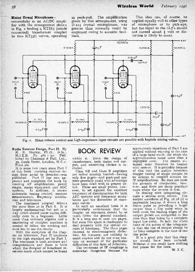
'
58
Mixing Crystal Microphones- successfully in an AC /DC. ampli- fier with the arrangement shown in Fig. 2 feeding a KTZ63 (triode connected) transformer coupled to two KT33C valves, operating
Wireless World February 1946
in push -pull. The amplification given by this arrangement, using D.ro4 crystal microphones, was greater than normally could be employed owing to acoustic feed- back.
euF
,/vvvv. 50,00011
This idea can, of course, be applied equally well to other types of microphone or to pick -ups, but the input to the 6L7's should not exceed about } volt or dis- tortion is likely to occur.
15,000 n
o INPUT
o
oo1¡LF
6L 7
5MR
OUTPUT
10,000 11
0I Mfl
,000 n
10,000 n o SpFT
soµF
+HT
50,000 fl
=osNF
-HT
Fig 2. Silent volume control and high- impedance input circuits are possible with heptode mixing valves.
Radio Receiver Design, Part IL By K. R. Sturley, Ph.D., B.Sc., M.I.E.E. Pp. 48o + xv. Pub- lished by Chapman & Hall, Ltd., 39, Essex Street, London, W.C.z. Price 28s. It is some two years since part I
of this book -covering receiver de- sign from aerial to detector -was published. Part II has now ap- peared and completes the book by treating AF amplification, power stages, mains equipment and AGC systems. In addition, it covers automatic tuning control, receiver measurements, frequency modula- tion and television.
The treatment adopted follows the same lines as in Part I. It is largely mathematical but not in a way which should cause undue diffi- culty even to a beginner. Little more than ordinary algebra and a smattering of complex numbers is needed to follow the working and even less to use the results.
With the exception of the chap- ter on television, Part II conforms to the high standard set by Part I. The treatment is both accurate and comprehensive and there is little which the designer of broadcast re- ceivers needs which cannot be found
BOOK REVIEW within it. Even the design of transformers, both mains and out- put, and smoothing chokes is in- cluded.
Class AB and Class B amplifiers are rather scantily treated- having only five pages -and push -pull sys- tems generally could with advantage have been dealt with in greater de- tail. These are small points, how- ever, to set against the excellent treatment of discriminators for both AFC systems and frequency modu- lation and the discussion of react- ance valves.
In such an excellent book it is particularly unfortunate that the chapter on television should be so much below the general standard. It is a long one of over roo pages, but even this space is inadequate to deal properly with the special cir- cuits of television. The, three pages devoted to electromagnetic deflec- tion, for instance, are unlikely to assist anyone and do not even con- tain an account of the particular difficulties of this form of deflection.
The treatment of IF couplings is somewhat dangerous because the
approximate equations of Part I are applied without warning to the case of a large band -width, for which the approximations cause more than a negligible error. The results ob- tained must therefore be treated with reserve. It is probably because of this that the author considers stagger tuning of single circuits to be inferior to coupled circuits for IF amplifications. He does not state the grounds of comparison, how- ever, and there are many practical cases where the reverse is true.
In dealing with integrating cir- cuits a serious error occurs. The output waveform of Fig. 16.18 (c) is impossible because it shows a long frame pulse as providing a larger output than a line pulse when in both cases the leading edges of the output pulses are completed in less time than that taken by a complete input line pulse. In fact, the whole basis of the action of the integrator is that the rise of output should be far from complete in the time of one line pulse.
It is a great pity that this chap- ter should have been included. Without it one could have nothing but praise for the book.
W. T. C.
www.americanradiohistory.com

February 1946 Wireless World 11111111111:111111.9111:11:-MO ME : , 3y
Advertisements 23
LINAGLOW LIMITED We have purchased from a prominent manufacturer valuable stocks of all types of Radio Components, New and Unused, ex- Government Surplus. As advertising space does not permit a full list, we have selected the following :
VITREOUS WIRE WOUND TUBULAR RESISTANCES, NEW AND UNUSED by Paignton, Watmel, Standard Tele- phones, Berco, etc." Up to IO watts, 1/-, from 10 -25 w., 1/6., from 25 -75 w., 2/ from 75-250 w., 3/6. Finest quality. Low Tolerance + or - 5 %. (1) 100.000 ohm. 2 watt ; (la) 4,000 ohms 6.6 w. ; (2) 50 obme 10 w. ; (8) 2 ohms 10 w. ; (4) 1.3 ohms } w. (6) 2.6 ohms } w. ; (8) 3.2 ohm. 1 w. ; (7) 20 ohms 4 w. ;
(8) 36 ohms 6.6 w. ; (9) 2.4 ohms 4 w. - (10) 16 ohms 1 w. ;
(11) 49 ohms 1 w. ; (12) 8.2 ohms } w. ; (13) 16 ohms 10 w. ; (14) 260 ohms 6.6 w. ; (15) 6,000 ohms 4 w. ;
(16) 100 ohm. 4 w. ; (17) 150 ohms 10 w. (18) 250 ohms 10 w. ; (19) 100 ohms 10 w. ; (20) 400 ohm. 10 w. ; (21) 500 ohms 10 w. ; (22) 5.000 ohms 6.5 w. ; (23) 1.000 ohms 4 w. ; (24) 600 ohm. 26 w ; (25) 2 ohms 25 w ; (26) 6,000 ohms 26 w. ; (27) 500 ohms 15 w ; (28) 1.000 ohms 16 w. ; (29) 1,600 ohm. 15 w. ; (30) 200 ohms 15 w. (81) 6,000 ohms 25 w. ; (82) 250 ohms 36 w. ; (88, 260 ohms 26 w. ; (34) 800 ohm. 20 w. ; (85) 10,000 ohm. 16 w. ; (86) 7,000 ohms (tapped at 2,000) 25 w. ; (37) 800 ohms 60 w. ; (88) 10,000 ohms 45 w. ; (89) 25,000 ohms 60 w. ; (40) tO 000 ohms 36 w. ; (41) 6,000 ohm. 75 w. ; (42) 3,600 ohms 76 w. ; (43) 2,500 ohms 60 w. : (44) 1 ohm 60 w. ; (45) 2,700 ohms 50 w. ; (46) 27,000 ohm, 50 w. ; (47) 2 ohms 50 w. ; (48) 200 ohms 25 w. :
(49) 5.000 ohms 75 w. ; (60) 26,000 ohms 25 w. ; (511 25,000 ohms 200 w. ; (52) 2,000 ohm. 200 w. ; (68) 10,000 ohm. 100 w. ; (54) 4,000 ohms 100 w. ; (651 1,200 ohm. 100 w. ; (56) 600 ohms 100 w. ; (57) 75,000 ohms 100 w. ; (58) 50.000 ohms 100 w. ; (59) 36 ohm, 100 w. ; (60) 45 ohms 100 w. ; (61) 100,000 ohm. 200 w. ;
(88) 1.000 ohm. (tapped at 500) 150 w. ; (63) 60 ohm., (tapped at 90) 130 w.;- (84) 6.3 ohms 100 w. ; (85) 20 ohms 160 w. ; (66) 20.000 ohm. 160 w. ; (67 7,000 ohms 150 w. ; (88) 20.000 ohms (tapped at 3.000 and 6,000) 100 w. ; (69) 6,000 ohms 150 w. ; (70) 2,600 ohms 150 w. ; (71) 125 ohms 100 w. ; (72) 200 ohms 160 w.
CARBON RESISTANCES by famous Manufacturers. Up to I watt, 3d.; up to 10 watts, 5d. All + or -5 per cent. (78) 140 ohm. 2 w. ; (74) 300.000 ohms 1 /3rd w. ; (75) 240,000 ohms 3 w ; (78) 200,000 ohms 3 w ; (77) 200 ohms 8 w. ; (78) 26,000 ohms 2 w. ; (79) 80,000 ohm. 3 w. ; (80) 3,000 ohm. 2 w. ; (81) 4,000 ohm. 2 w. ;
(82) 20,000 ohms 2 w ; (88) 80,000 ohms } w. ; (84) 5,000 ohms 1 w. ; (85) 1,000 ohms } w. ; (86) 100 ohm. 1 w. ; (87) 3,000 ohms 1 /3rd w. ; (88) 6,000 ohms } w. ;
(89) 4,000 ohm. 1 w. ; (90) 2,000 ohms I w. ; (91) 4,000 ohm. } w ; (92) 800 ohms 1 w ; (98) 600 ohms 1 /3rd w. ; (94) 600 ohms 1 /3rd w. ; (95) 26 000 ohms 1 /3rd w. ; (98) 30,000 ohms 1 /3rd w.: (97) 16,000 ohms 1 /3rd w.; (98) 180,000 ohms 3 w.; (99) 260,000 ohms 1 /3rd w.; (100) 60,000 ohms 1 /8rd w. ; (101) 20 ohms 3 w. ; (102) 51 ohm. 2 w. ; (108) 51 ohms 8 w. ; (104 ; 88 ohms w. ; (106) 24 ohms } W. ; (108) 500 ohms 2 w.; (107) 100 ohm. 2 w. ; (108) } meg. 2 w. ; (109) 1 meg. I w. (110) 1 meg. 2 w. ; (111) 2 meg. } w.
PAIGNTON HEAVY DUTY FILAMENT RESISTANCES
with two adjustable tappings all at 15s.6d. ea, (112) 17.5 ohms 8 amp.. ; (118) 7.6 ohms 4 amps. with slider.
B.P.L. UNIVERSAL TEST SET D.C. Volts.
0.76 MV 0.10 0.60 0 -100 0.600
D.O. =lamps. 0- 1 0. 10 0.100 0.600
A.C. Volts. 0. 10 0. 60 0.100 0 -600
Re, .tance, 0. 10,000 ohms. 1,000 ohms per volt on all voltage range,. Accuracy 2 per cent. except for lower values on the 10 volt A.C. range. Dimension., 6' x 41' x 35'.
Price £8 . IT . 6
POTENTIOMETERS by Morgan, Stackpoole, etc., all values
Is. 3d. each without switch. (114) 60,000 ohms ; (115) 6,000 ohms ; (118) 600,000 ohm, ; (117) 10,000 ohm. ; (118) 2 meg. ; (119) } meg. ;
(180) 1,000 ohm. with switch, 2/3.
METERS (167) Volt meters, panel mounting 35', M.V.E. type AO, 25 %V8, 15 ; (188) 35' panel mounting, 0-100 m.a., Q2101. ; (189) 2' panel mounting, 0 -2 m.a., E2 10s. ; (170) 2' panel mounting, 0 -50 m.a., Q2 101. ; (171) 2' panel mounting, 0 -5 m.m., E2 101.
TRANSMITTING COILS Finest quality Silver -plated. All at 10/6 ea. (172) 1.3 microhenrlee, (173) .9 mlmohenriee, (174) 1.5 mieroheorie., (175) 1.7 microhenries, (176) 2.2 micro - henries, (177) 2.7 mimohenriee.
IT IS ESSENTIAL THAT OUR REFERENCE NUMBERIS QUOTED WHEN ORDERING ANY OF THE ABOVE ITEMS.
CINTONE 5 -VALVE MIDGET SUPERHET
CONSTRUCTORS KIT
Complete with Cabinet 16 - 50, 200 -550 metres
A SUPER -SENSITIVE & SELECTIVE CIRCUIT Brief specification : Frequency changer, 6 tuned circuit 466 K.O.'s iron cored I.F.',. 4 -watt output. P.N. speaker and output transformer, all valves, chassie, practical and theoretical diagrams. Parte list, nuts, bolts and wire and modern cabinet. Dimensions) : 1210. x 81n. x 610. deep. Ready to assemble. 200/260 volts, A.C. Parts new and ex- television. Including Purchase Tax... 131 GflS Case and packing 10/- extra (refunded 2 upon return of case).
AMERICAN MIDGET RADIOS G I Electric Model L643
6 -valve 8uperhet with built -)n frame aerial, AO/DO 100/260 volta 200/650 metres. Fine quality figured walnut cabinet.
Price £15.5.10
CONDENSERS Tubular paper, Block paper, Mansbridge, etc., by famous manufacturers. Dubilier,
T.C.C., etc, (121) Dubilier .01 mfd. 6,600 volt working, 60 cycle type 193/6P1, in porcelain caca, 1018. (122) 00046 mid. tubular 30,000 volt working, 35/. ; (183) .005 mfd. mica eonden,er, 6,000 volt working, porcelain case, '7/8 ; (154) A. above, .0016 mid. 25,000 volt DO working, 1018 ; (126) .01 mid. tubular tag end, 1,600 volt working 8/- ' (126) .0026 mfd. ceramic 26,000 volt working, 22/5 ; (127) .004 mid. mica 4,000 volt DO teat. 5/6 ; (128) glom and pasolin transmitting aerial condenser, .0002, 21)- : (159) .1 mfd. 500 volt working tubular tag end, 2/- ; (130) as above, 1,000 volt working, 2/6 ; (181) .01 mid. 1,000 volt working tubular, 3/- (132) ceramic condenser, 100 pfd. + or - 2 per cent. wire end, 11 -; (133) block condenser, 226 mid. +2.26 mfd. 6,000 volt DO working, 25/- ; (134) block condenser, 4 + 2 mid. 4,500 volt DO working, 25/- ; (135) block condenser 6 + .6 + 1 mfd. 3,600 volt DO working, 17/6 ; (136) block condenser 4 mfd. 1,000 volt DO working, 10 /- ; (187) block condenser, 2 mfd. 1,000 volt D.O. working, 8/- ; (138) block condenser, 4 mfd. 1,600 volt DO working, 8/6 ; (139) block condenser, 10 mid. 1,600 volt DO working, 15/- ; (140) mica tubular. .01 mid. 5,000 volt DO working, 5/-; (141) 40 mid. 600 volt working tubular ceramic, 5/- ; (142) mica tubular .001 mfd. 260 volt DO working, 2/6; (143) tubular paper .5 mfd. 350 volt DO working, 1/. ; (144) tubular paper .02 mfd. 360 volt DO working, 9d. ; (145) tubular paper .75 mfd. 350 volt working, 1/- ; (148) sic. Bat type .01 mfd. 760 volt DO working, 2/6 ' (147) tubular paper .076 mfd. 460 volt DO working, 9. ; (148) mica block type 90005 mfd. 850 volt working, 1/- ; (149) as above, .0003. 1/6; ; (150) block type paper 10 mid. 400 volt DC working. 3/8 ; (151) .02 tubular paper tag end 350 volt working, 8d. ; (152) .01 tubular paper tag end 1,000 volt working, 2/8 ; (158) Bat mlos .0002 mfd. 360 volt working, 6d. ; (154) 6 mfd. block paper 400 volt DO working, 1/6 ; (155) 2 mid. 400 volt DO working, block paper, 2/- ; (158) .1 mfd. block paper 1,000 volt DO. working, 5/- ; (157) 8 mid. 400 volt DO working, block paper,
; (158) mica type .0001 1,600 volt DO working, 5/- (159) 76 mfd. paper, bakelite ease, 50 volt DO working, 1/8 ; (180) 1 mfd. tubular paper, tag end, 350 volt working ; (161) .002 mid. mica Bat tag end type, 2,200 volt DO working, 5/..
TRANSFORMERS AND CHOKES (162) heavy duty transformer : primary 230 volt 60 cycle, secondary 11/12.8 volts 70 amps, 25. (168) 230 volt 60 cycle primary, 13/15 volta secondary, 60 amps, 25 ; (164) Ferrant) OP161 output transformer, tropical windings, ratlos 1 /1, 2.7/1, 1.6/1, price 15/-
151- ' (186) 280
volt primary 12 volt secondary, 1.87 amp., ; (188) L.F. Choke. 30 henries 1,000 volt DO, 100 ma., 25/--
SUNDRIES (178) Relays, 3,000 ohms double pole heavy contact. single pole light contact, 2/ -. (179) 100 watt Cosmos lampe, 230 volt, double -ended tnbulars, 3/6 (180) Cosmos Neon Indicator Bulbs, I watt B.O., 80 /100 volts, B4. ; (181) Mulrhead communication receiver dials, preelelun model, 0.180 degrees 4' geared 60 /1 ratio, 30/ -; (189) Belling a Lee 15' 60 m.a. glass cartridge fumes, 1d. each ; (183) Eddystone short- wave microdeneere, No. 1130, 600 mid.. 1/ -: (184) lema., very useful for the work -bench. Box containing 260, 0-4-6 and 8 B.A., varying in size from 5' to 3" cadmium and chromium plated. Various oxyd)sed and rust-proof finishes, 3/6 per box. ; (186) Assorted parcel, Lies (various .1,e,), Terminal Tags, Anode Connectors, Cable Luge, etc., 1/8.
4 VALVE T.R.F. RADIO Latest model, Pue quality reproduction Band Pus. Very selective 8' P.N. speaker, 3 watts undistorted output. AO mains 200/250 volts. Valves, 6K7, 6K7 6116, 6 %5. Contained in One quality highly polished cabinet. i
Price £12 . 15 . O
POST ORDERS ONLY HANDLE SHOWROOMUCAL ER OR C.O.D. TRADE UNTIL FURTHER NOTICE
'Phone: LINAGLOW LTD., Dept. MO 56, 61, HIGHGATE HIGH ST., N.6 Mo9 d1e
www.americanradiohistory.com

aWESTINGHOUSE0
24 Advertisements
HERE IS THE NEW
TRANSFORMER THAT HAS i+,/
Wireless World YOU CAN STILL GET
February 1946
PORTABLE P.A. EQUIPMENT
IF YOU ORDER NOW
The R.S. "Universal Fif- teen " is the most truly portable " portable " out -
fit yet made available. Operating equally suc-
cessfully on either AC or DC at all voltages from 200 to 240, the two loudspeakers, micro- phone, amplifiers and cables are quickly assembled into one
compact unit ready for easy
transport. Write now for fullest details -but, a word of warn- ing, only limited supplies are
available.
iPS.0.0yGi R. S. AMPLIERS LTD., 2-4, HIGHPIELD RD., SHEPPERTON, MIDDLESEX
rELEPHONE - WALTON - ON - THAMES 1019 174
SUPERB TECHNICAL DESIGN FINEST QUALITY MATERIALS
HIGH OPERATIONAL EFFICIENCY
GUARANTEED RELIABILITY
BEAUTIFUL APPEARANCE BRIEF DETAILS OF THE RANGE . . . .
Mains Transformers, 5 -5,000 Watts. ; Input and Output Transformers ; Filter Chokes.
. . . . AND OF THEIR CONSTRUCTION High Quality Silicon Iron laminations; wired to B.S.S. Standards ; finest grade insulation ; Die Cast Streamline Shrouds ; Black bakelite Ter- minal panels ; High Vacuum Impregnated coils layer wound with condenser tissue interleaving ;
Porcelain terminals insulated and /or silver plated soldering tags.
WODEN TRANSFORMER CO. LTD., MOXLEY ROAD, BILSTON, STAFFS.
Telephone : BILSTON 41959
A COMPLETE RANGE of metal rectifiers is available for :
H.T. SUPPLIES to radio receivers of all types and transmitters.
L.T. SUPPLIES to transmitters.
G.B. SUPPLIES to transmitters and receivers.
BATTERY ELIMINATORS AND TRICKLE CHARGERS for battery -
operated receivers.
DETECTION AND A.V.C.
Write for literature to Dept. W.W.
WESTINGHOUSE BRAKE & SIGNAL CO. LTD. Pew Hill House Chippenham Wilts
www.americanradiohistory.com

February 1946 Wireless World 59
MULTI -CARRIER
COMMUNICATION SYSTEM Diversity Transmission for Mobile Working
IN 1939 three bands of f re- quencies in the vicinity of loo Mc /s were allotted to the
Home Office for use by the police and fire services, the actual bands concerned being 78.5 to 82 Mc /s, 95.5 to loo IV.Vc /s and 128 to 13r Mc /s respectively. Subsequent tests have shown that with these frequencies it is possible to provide a two -way telephone service of good standard and reliability with mobile units in all the large cities, including Greater London. With a well -sited transmitting aerial some 400 to 500 feet high a service range of about 20 miles can be assured.
The penetration of streets, steel - framed buildings and even tunnels is extremely good, and so far there has been no trace of interference from long -distance sources, such as has proved so troublesome with some of the contemporary services operating on the 3o to 4o Mc /s police bands. Further, tramcar, trolley -bus and general switching and commutator noises, often so troublesome on the pre -war tele- vision frequencies, are virtually non -existent above loo Mc /s and there remains only ignition noise as the major source of interference.
Whilst this could be made innocuous by using frequency modulation, certain technical difficulties arise when two or more transmitters are used, with synchronised modulation, for covering an extensive service area. A comparable reduction of inter- ference was found possible with amplitude modulation by fitting suitably designed noise limiters in the receivers, and their effective- ness was most convincingly demonstrated during a recent tour of the London Metropolitan area in a VHF -equipped Home Office vehicle.
The need for more than one transmitter to ensure reliable coverage of a large rural or built - up area was revealed quite early
in the development of the scheme, and it was realised that multiple transmitters strategically located throughout the required service area would have to be provided.
The possibility of synchronising transmitters at these high fre- quencies was ruled out and eventu- ally a scheme was evolved in which two or more transmitters, supplied with synchronised and correctly phased amplitude modu- lation, radiate on closely related radio frequencies. The carrier frequencies of the transmitters comprising a single installation are set sufficiently far apart to avoid audible beats, yet close enough to be within the band -width of the receivers. This is about roo kcls.
service areas are not well defined, but are intricately interwoven owing to the lay of the land of the country in the rural districts and to the structural nature of build- ings in the built -up areas.
Initial tests were made with two transmitters on a common site and with their aerials separated by several wavelengths ; an arrange - meñt that might be described as diversity transmission. With both transmitters radiating, no distor- tion could be detected anywhere within the service area, while the average field strength was con- siderably greater than that pro- vided by a single transmitter.
With a single transmitter radi- atin^ and when cruising in built -up
VHF transmitter and receiver, with two motor generators supplying HT, mounted on_a removable tray and fitted into the luggage boot
of a patrol car.
This requirement was imposed in order to obviate the need to retune the mobile receivers when passing from the service area of one transmitter to that of another. At these very high frequencies
areas, signals were often subjected to a bad " flutter," presumably due to standing wave patterns brought about by reflection from the adjacent buildings. The measured variations in signal
www.americanradiohistory.com

6o
Multi- Carrier Communication System -
strength often amounted to as much as io db at points only a few feet apart. Where two carriers were used the " flutter " effect was considerably 'reduced, and in areas where the AVC could operate effectively a perfectly steady signal resulted.
The initial tests having proved so satisfactory, a more ambitious scheme was launched to cover Greater London. For this purpose three transmitters were erected, one located on Hampstead Heath, another at the Crystal Palace, and the third at Newlands Corner, near Guildford, these sites being chosen because of their commanding elevation.
Frequencies in the vicinity bf roo Mc /s are used for the three main transmitters, which give about zoo watts carrier output and are modulated from a common source, in this case the Hampstead station, over a radio link on 13o Mc /s. Precautions are taken to ensure that the modulation phases and amplitudes are ap- proximately equal at all trans- mitters.
Transmission from the mobile units is made on any one of the available bands, and this is re- ceivable at all the three trans- mitting sites. From each of these
AREA CONTROL
Wireless World
Where facilities permit, land lines would be used for the relay- ing services, but elsewhere radio links may have to be employed. Radio control by VHF links was in fact used for an experimental system installed to cover a large rural district embracing parts of the counties of Buckinghamshire, Berkshire and Oxfordshire. The control point was at Reading.
This system employed three transmitting stations each of loo watts output and operating on the triple carrier frequencies of 96.32 Mc /s, 96.3o Mc/s and 96.28 Mc /s respectively. The three trans- mitting sites were separated by about 20 miles in each case, and they were all about 600 feet above sea level.
Of the three transmitters, one served as the master control centre through which all in- coming and outgoing messages had to pass. The other two trans- mitters were merely satellite sta- tions and served to relay the messages to and from the mobile patrols.
A schematic block diagram showing the various transmitters and receivers used at the different sites is reproduced here from a paper read before The Institution of Electrical Engineers by J. R. Brinkley. Outgoing traffic is conveyed over the radio channels
MASTER CONTROL
February 1946
the control link between the master station and the two satel- lites, and carries the modulation for the ioo -watt traffic trans- mitters at these sites.
Geographical considerations necessitated the transmitters being situated closer together than was actually desirable, and there was a wasteful overlap in the centre of the triangle they formed, but it admirably demonstrated the out- standing advantages of the multi- carrier system over a single station installation, and in this respect served its purpose.
So far most of the work carried out has been of a; exploratory nature, and as a consequence the equipment used is of a mobile type. Even the main transmitters and power supplies are assembled in specially designed lorries, although the grid electric supply can be used wherever access to it can be had. Likewise where line telephone circuits are available the radio links could be omitted, but these are matters of detail that have to be worked out for each separate installation.
The equipment fitted to the mobile units, which are mainly private motor cars, consists of a pre -tuned crystal controlled super- heterodyne receiver having a band width of roo kc /s and a 7 -watt VHF transmitter. Power for
SATELLITE I
f3
\fl(c) 96.28 Mc/5
f2 \ i(e) y 96 J2
Mc/s
MOBILE
0
HIGH -POWER TRANSMITTER
LOW-POWER TRANSMITTER
RECEIVER
Block schematic lay -out of the
the signal is relayed to the control station, where they are combined and transmitted to the_area con- trol centre.
SATELLITE 2
triple- carrier communication system operated entirely by radio links.
marked fl" (a),T(b)'and (c)'and f3, whilst the incoming traffic uses the channels f =, f, and fz respectively. The; !é channel f, is
operating both these units is obtained from small motor gener- ators operated from the car accumulator.
www.americanradiohistory.com

February 1946 Wireless World
As the receiver is pre- tuned,'it, and the transmitter, can be stowed anywhere that is convenient in the vehicle, since switching on and off and changing over the aerial can be effected by remotely con-
its usefulness in connection with train communications and doubt- less many other uses will emerge.
The Home Office has been mainly responsible for the field work involved in the development
.11113102. One of the mobile Too -watt VHF transmitters with its ancillary equipment mounted in a vehicle for use at temporary trans-
mitting sites.
trolled relays. Thus the only items of equipment that need be acces- sible are the microphone, loud- speaker, on -off and changeover switches. And these latter two items could be operated by a press -to -speak button on the handle of the microphone. Alter- natively, voice -operated switching could be used.
In one of the illustrations reproduced here the mobile equip- ment is shown mounted in the luggage boot of a car.
The multi- carrier scheme would appear to have many applica- tions outside the police and fire services for which purpose it was originally developed. Indeed, it is learnt that some exploratory tests are already in hand to assess
of the scheme, while active collaboration in the technical development and production of the actual equipment havé been shared by the General Electric Co., and Stratton & Co.
"Wireless World
QUALITY AMPLIFIERS"
IN Fig. 2 of this article in the January issue, the value of the
bass -lift capacitor was omitted. This capacitor is in series with the 22,00o -ohm resistor, and it should have a value of 0.05 AF.
Two of the resistors included in the i -watt list, R, and R15, should preferably be of the i -watt type.
MAINTAIN SUPREMACY
IN THE FIELD OF COMMUNICATIONS
FOR TEMPERATURE COMPENSATING
& GENERAL PURPOSE CONDENSERS
STYLE
CAPACITY RANGE
P080 P100 P120
N750 Hi -K
MMF MMF MMF
A and K I -9 1-51 56-560
B and L 10-18 52 -110 560 -1,500
C and M. 19-63 III -360 1,500 -4,700
D 64-93 361 -510 4,700 -6,800
E 94-150 511 -820 6,800- 12,000
F 151 - 200 821 -1,100 12,000 -15,000
G - - 15,000 -22,000
H - - 22,000- 33,000
Tolerance on Temperature Co- efficient is- 30 parts/millioni°C or ±15%, whichever is the greater.
Note : Styles A, 8, C, D, E, F, G and H are non -insulated units. Styles K, L, and M are insulated.
MAY WE SEND YOU SAMPLES FOR TEST OR FOR PROTOTYPES ?
ERIE RESISTOR LIMITED CARLISLE RD THE HYDE HENDON
LONDON N.W.9 TELEPHONE: COLINDALE 8011
FACTORIES: LONDON ENGLAND TORONTO CANADA ERIE, PA. U.S.A
www.americanradiohistory.com
62
UNBIASED By FREE GRID
Universal Telecommunication NOW that the transatlantic tele-
phone service is in operation once again I find myself in the Alice -in- Wonderland situation of being able to get in touch with any- body in Tennessee or Texas and quite unable to get a message home from a taxi to Mrs. Free Grid to say that I am detained by business and shall not be home until late. I found myself in this predicament only last week when dictating some important letters to my secretary as she and I sped along the Great North Road to Brookmans Park. It is, of course, possible to stop a taxi at the nearest 'phone box, but why in the name of all that is scientific is not each public and private vehicle equipped with a proper USW transmitter -receiver designed to contact the nearest telephone ex- change ?
I think that the least excuse for this sort of omission is to be found on our trolley -bus systems. Here we have a flock of public vehicles all linked by an insulated wiring system to a central point. These wires could be used as the carriers of a comprehensive " carrier current " system and so no ether space would be occupied. Overcoming the effects of the " flashes and bangs " which
III1gIILlfllqi
I
Dictating important letters.
seem inseparable from trolley bus systems would provide excellent scope for inventive ingenuity- and would contribute much valuable data to the final elimination of inter- ference from our domestic receivers.
Underneath our streets are a multiplicity of waste pipes and other metal conductors, all of which could be made to serve as " carriers " in order to link private cars and other vehicles with the nearest telephone
exchange. The fact that they are not insulated does not, of course, veto matters where modern UHF technique is con- cerned. On highways in the country there are roadside telegraph wires to act as carriers, and so only in the country by- ways should we have to employ a direct USW link from vehicle to telephone exchange al- though even in this case hop would probably be made to the nearest tele- graph wires or other metal conductor.
It is no use saying that the ether is already overcrowded and that there are no ether chan- nels available even for hopping from car to the nearest con- ductor. Actually, of course, the number of channels is infinite, for I take it that we can never get to a wavelength so short that it is zero or to a frequency so high that it is infinite. Mind you, I am not saying that I have worked all this out in detail. I am far too busy and in any case it is none of my business, it being more a matter for what the newspapers, when discussing Government plans, refer to rather contemptuously as the " permanent officials."
Wireless World February r946
Golfers Menaced MY first impression when the
photograph reproduced here- with was sent to me for my com- ments was that it was phoney in more senses than one, - and without attributing any dishonest or dis- honourable motives to anybody associated with the photographs or to those appearing in it I am still of that opinion. The picture origin- ated in America and the idea is that the earnest golfer should always be in a position to receive an urgent business call or a message from his wife.
Now, as all fellow -followers of the Royal and Ancient game will agree, who on earth, especially an Ameri- can, has the remotest desire to risk being put off his game by an un- timely message from anybody ? The whole thing betrays utter and crass ignorance of the golfer's mind or
The Links radio link.
even of the fundamental idea behind the great game. It is one of the few pursuits which enable a man for a brief spell to enter a new and enchanted world where wives, busi- ness and all the other evils to which the flesh is heir can be momentarily forgotten.
Whenever I receive a photo- graph of this sort I always have a nasty feeling that it is a preliminary to my being asked to invest my hard -earned cash in some highly imaginative financial scheme of which I have had many instances in my time. Probably the most inter- esting of a radio or like nature was one known as the " Transatlantic Homing Guide for Liners." The idea was simple. Ships were to be provided with suitable electrical ap- paratus whereby they might, as the prospectus said, pick -up by in- duction the magnetic radiation from the transatlantic telegraph cables, thus being led straight from Liver- pool to New York in the foggiest weather, using the cable as a homing beam.
For the moment even I was struck by the stupendous possibilities of the whole idea until I recollected that the screening effect, not only of the metallic covering but also of the equally restrictive salt -water shield, would put paid to the whole scheme. Apart from that, I suppose the cable people took a pretty dim view of the enterprise, as it was not proposed to pay any fee or royalty of any kind for this gratuitous use of the cables.
www.americanradiohistory.com

February 194.6 Wireless World
Letters to the Editor
Problems of Export B.B.C. Transmissions Pickup Construction
Export Trade I WHOLEHEARTEDLY agree
with Mr. Cribb (your Septem- ber, 1945, issue) on export re- ceivers. In the tropics reception on medium waves is marred by static and is useless except for local broadcasting confined to ground waves only. In East Africa we have only one station and that of very low power ;
consequently we are dependent on more powerful distant stations, working on short waves of 13 to 6o metres. To obtain satisfactory reception, attention must be paid to elimination of frequency drift and attainment of high sensitivity and selectivity.
What is required is standardisa- tion of components, particularly valves. This would restrict the range of spares which must be carried by dealers and ensure ser- vicing of radios irrespective of make and manufacture. All physical dimensions and charac- teristics must be standardised and the range made as compact as possible. While American manu- facturers are devoting their energies to plugging certain pre- ferred types, 'taking interchange- able components, British manu- facturers cannot even agree on standardisation of valves. A lead in the pooling of export effort has been given by British manufac- turers of small machine tools which can be improved upon by radio manufacturers to their general benefit. Yet the report of the I.E.E. meeting on valve standardisation in your April issue makes depressing reading overseas.
British manufacturers expose a grave weakness in their lack of understanding of export require- ments and insistence on each going their own way. There are perhaps 1o,000 radios throughout East Africa ; that is, 10,000 cover- ing about 450,000 square miles. Service is obtainable at three or four centres in that area. Users may have to pack and send their
radios 500 -600 miles, sometimes in lorries over rough roads, for the most simple repair or replace- ment, as with non -standard com- ponents the dealer may have to do considerable work if the maker's type component is not available. With standardised components, in many cases users could, and would, do simple replacements themselves. This is where over- seas servicing differs from that in the U.K., and the Americans have long known it.
Further, by adopting standards produced on a pool basis the cost of manufacture would be bound to drop and British radios would become competitive. Competition must remain to ensure the best possible deal to the user, but the competition should not lie between manufacturers in the same country to the extent it now does in the U.K. ; instead, in the main, it should lie between exporting countries. So now, British Manu- facturers, be up and doing.
Dar -es- Salaam, MAHMOOD. Tanganyika, E. Africa.
"Wartime Hangovers " E, the undersigned radio en-
gineers, were very interested to see the paragraph entitled :
" Wartime Hangovers," in the January issue of Wireless World and thoroughly endorse your remarks.
In addition to your request that a statement should be made by the BBC on this subject, we think it high time some action was taken to bring the present stan- dard of transmission up to some- thing much more worthy of the prefix " British."
Apart from general complaints, such as lack of apologies for pro- gramme breaks, faulty recordings, incorrect transmissions and the general low standard of operating, we have in this area certain local complaints some which we enu- merate as follows : -
(a) Ever since the changeover in system of distribution at the
63
THE FLUXITE QUINS " AT WORK
" Hullo 1 What's happened in here 7
The end of our wireless, I fear Fixing wires with FLUXITE Is perfectly right
But not with the current_on, dear 1"
See that FLUXITE is always by you - in the house - garage - workshop - wherever speedy soldering is needed. Used for over 30 years in Government works and by leading engineers and manufacturers. Of all Iron- mongers-in tins, 8d., 1/4 & 2/8.
Ask to see the FLUXITE POCKET BLOW LAMP, price -2/6.
TO CYCLISTS I Your wheels will NOT keep round and true unless the spokes are tied with fine wire at the cross- ings AND SOLDERED. This makes a much stronger wheel. It's simple -with FLUXITE -but IMPORTANT.
The FLUXITE GUN puts FLUXITE where you want it by a simple pressure. Price 1/6, or filled, 2/6.
ALL NiCIIANIC$ WILL
IT 11110tlifiES ALA SOLDERING
Write for Rook on the ART OF "SOFT SOLDERING and for Leaflets on CASE- HARDENING STEEL and TEMPERING TOOLS with FLUXITE. Price Id. each.
FLUXITE LTD. (Dept. W.W.), Bermondsey Street, S.E.I
www.americanradiohistory.com
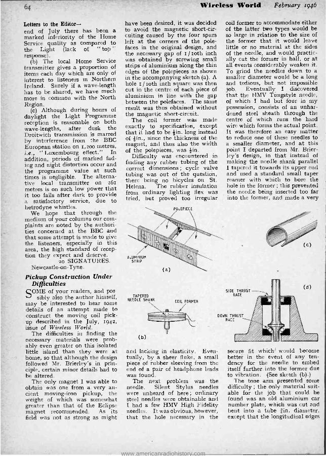
64
Letters to the Editor - end of July there has been a marked inferiority of the Home Service quality as compared to the Light (lack of " top " response).
(b) The local Home Service transmitter gives a proportion of items each day which are only of interest to listeners in Northern Ireland. Surely if a wave -length has to be shared, we have much more in common with the North Region.
(c) Although during hours of daylight the Light Programme reception is reasonable on both wave -lengths, after dusk the Droitwich transmission is marred by interference from the BBC European station on 1,2oo metres, i.e., " Luxembourg effect." In addition, periods of marked fad- ing and night distortion occur and the programme value at such times is negligible. The alterna- tive local transmitter on 261 metres is on such low power that it too fails after dark to provide a satisfactory service, due to hetrodyne whistles.
We hope that through the medium of your columns our com- plaints are noted by the authori- ties concerned at the BBC and that some attempt is made to give the listeners, especially in this area, the high standard of recep- tion they expect and deserve.
20 SIGNATURES. Newcastle -on -Tyne.
Pickup Construction Under Difficulties
SOME of your readers, and pos- sibly also the author himself,
may be interested to hear some details of an attempt made to construct the moving coil pick- up described in the July, 1942, issue of Wireless World.
The difficulties in finding the necessary materials were prob- ably even greater on this isolated little island than they were at home, so that although the design followed Mr. Brierley's in prin- ciple, certain minor details had to be altered.
The only magnet I was able to obtain was one from a very an- cient moving -iron pickup, the weight of which was somewhat greater than that of the Eclipse magnet recommended. As its field was not as strong as might
Wireless World February 1946
have been desired, it was decided to avoid the magnetic short -cir- cuiting caused by the four spurs left at the corners of the pole - faces in the original design, and the necessary gap of r / loth inch was obtained by screwing small strips of aluminium along the thin edges of the polepieces as shown in the accompanying sketch (a). A hole r / loth inch square was then cut in the centre of each piece of aluminium in line with the gap between the polefaces. The same result was thus obtained without the magnetic short -circuit.
The coil former was made exactly to specification, except that it had to be tin. long instead of +in., since the thickness of the magnet, and thus also the width of the polepieces, was tin.
Difficulty was encountered in finding any rubber tubing of the correct dimensions; cycle valve tubing was out of the question, there being no bicycles on St. Helena. The rubber insulation from ordinary lighting flex was tried, but proved too irregular
ALUMINIUM STRIP
(a)
TAPERED NEEDLE SHANK
COIL FORMER
(b)
coil former to accommodate either of the latter two types would be so large in relation to the size of the former that it would leave little or no material at the sides of the needle, and would practic- ally cut the former in half, or at all events considerably weaken it. To grind the needles down to a smaller diameter would be a long and tedious, but not impossible job. Eventually I discovered,
that the HMV Tungstyle needle, of which I had but four in my possession, consists of an unhar- dened steel sheath through the centre of which runs the hard wire which forms the actual point. It was therefore an easy matter to reduce one of these needles to a smaller diameter, and at this point I departed from Mr. Brier - ley's design, in that instead of making the needle shank parallel I tapered it towards its upper end and used a standard small taper reamer with which to bore the hole in the former ; this prevented the needle being inserted too far into the former, and made a very
SIDE THRUST RACE
DOWN THRUST RACE
and lacking in elasticity. Even- tually, by a sheer fluke, a small piece of rubber sleeving from the end of a pair of headphone leads was found.
The next problem was the needle. Silent Stylus needles were unheard of here ; ordinary steel needles were obtainable and I had a few HMV High Fidelity needles. It was obvious, however, that the hole necessary in the
O
secure fit which' would become bettei in the event of any ten- dency for the needle to embed itself further into the former due to vibration. (See sketch (b).)
The tone arm presented some difficulty ; the only material suit- able for the job that could be found was an old aluminium car number plate, which was cut and bent into a tube /in. diameter, except that the longitudinal edges
www.americanradiohistory.com
February 1946 Wireless Vi'orld
did not meet, leaving a gap of about ¡in. between the edges on the underside. See sketch (c).
In view of the recommendations by certain subsequent contribu- tors as to the importance of abso- lute freedom of the pivoting of the tone -arm both horizontally and vertically, I modified the pivoting base of a Garrard pickup by mak- ing a vertical thrust ball-race at the bottom of the pivot spindle, and a side thrust race at the top, as shown in sketch (d).
The coupling transformer was made up according to specifica- tion, but I was unable to obtain Mumetal for the core, having to use the laminations from a scrapped AF transformer of small dimensions, cut down to the measurements given.
I have not been able to con- struct the low -pass filter recom- mended, due to 'lack of wire, and I must admit I was also somewhat put off by the very large dimen- sions of the completed filter unit.
The pickup feeds via the coup- ling transformer to the grid of an extra stage of amplification pro- vided for gramophone only, using an L63 resistance coupled to the grid of the triode section of an EBC3, in the anode circuit of which is included the tone -control networks used in the Wireless World Communications Receiver, with the exception of treble boost, which is arranged in the feedback network in the amplifier itself. This stage feeds the Wire- less World DC Quality Amplifier, modified to run on AC supply, using KT6is in the output stage.
The results, using full bass boost, and one degree of treble cut have given immense pleasure and satisfaction, and are a very sub- stantial improvement over the results with a moving -iron pickup of modern design by a famous maker. All who have heard it and compared it with the latter pickup have remarked on the " cleanness " of the reproduction, and the complete freedom from distress on heavy orchestral pieces. There is no sign of any bass resonance whatsoever, and the scratch noise from modern recordings is not excessive, al- though, no doubt, a properly de- signed filter, rather than ordinary treble cut, would improve matters.
The downward pressure re-
quired is not more than 13 grammes, and the needle shows no signs of enlarging the hole in the coil former, or working loose.
I have not yet taken a curve of the response, but the needle of an output meter across the output transformer primary has been watched whilst playing through HMV gliding frequency record, DB4o37, and showed no signs whatsoever of any peaks of troughs. There seems to be some small loss of extreme treble, and I wonder whether some reader who knows more about this sub- ject than I do can suggest the reason. Might it be due to the type of needle I am using?
G. M. CATTLEY. Island of Saint Helena.
" FUNDAMENTALS OF RADAR "
Potential Accuracy of" Oboe "
THROUGH an arithmetical error, a misleading im-
pression of the high navigational accuracy obtainable from the Oboe system was given in the last paragraph on p. 25 of our January issue.
The amended ' relevant para- graph is reproduced below, with corrections italicised.
If the velocity of propagation is taken as 200,000 miles per second, to simplify the arithmetic, the delay per mile of range in the Oboe system will be ro micro- seconds. If we can measure time intervals with an accuracy of r / ro microsecond, therefore, we can determine position lines to within 20 yards. This does not mean that the position can be determined accurately as within 20 yards of a chosen point. In Fig. 5 is shown the error diagram when the two fixed stations are ioo miles apart and the position lies on the two 600 -mile position lines within measurement accuracy. For this particular example, which is a very simple one, the long diagonal of the slightly curved parallelo- gram is six times the length of the short diagonal, and the short diagonal is approximately equal to the range error. Thus, if the error in time measurement is r / roth microsecond, the error in position may be as much as + 6o yards along the arc of the posi- tion lines.
65
GALPI NS ELECTRICAL STORES,
408, HIGH ST., LEWISHAM,
LONDON, S.E.13.
'Phone: Lee Green 0309.
TERMS: CASH WITH ORDER. No C.O.D.
ELECTRIC LIGHT CHECK METERS, first -class condition, electrically guaranteed, for A.C.. mains 200/250 volts 50 cy. 1 phase 5 amp. load, each 12/6.
METAL RECTIFIERS, output x2 volts, x amp. 17/6.
LARGE PAXOLIN PANEL, size 14x7x1iu., fitted massive switch arm, 12 large studs and contact blade, very smooth action, price 7/6 each. X -RAY TRANSFORMER in oil, input 200 v., output 80,000 volts, rating 5 K.V.A., with Coolidge winding, £50 ; ditto, 24 K.V.A. at 90,000 volts, £35 ; ditto, dental type, 45,000 volts, £30.
FLUORESCENT SCREENS, 15 x 12, with lead glass, £5.
LARGE FAN MOTORS, all direct current, approx, 1 h.p., 110 v. series wound in fast -class condition. 15/- each. D.C. MOTORS, as above, only for 220 volts, in perfect order, 20 / -. each. ROTARY CONVERTER, input 230 v. D.C., output 230 v. A.C., 50 cycle, single phase, 11 kW., con- stant rating, a high -grade job of very solid con- struction, £35.
TRANSFORMER CORE to suit 21 kW. trans- former, complete with clamps and bolts, 25/ -. LARGE OUTDOOR BELLS, 110 v. D.C. working, Bin. gong, 17/6.
D.C. MOTOR, totally enclosed, shunt wound, 220 v., D.C. 1/10 b.h.p., large size, high -grade, 46/ -. AUTO TRANSFORMERS, tapped 0 -110- 200 -220- 240 step up or down, 500 watts, 63/10/0 ; 2,000 watts, £9.
BLOCK CONDENSERS, large size, in metal cases, 20 M.F., 300 v. A.C. working, 15/ -. ROTARY CONVERTOR, input 220 v., D.C. at 9 amps., output 68/125 volts, five hundred cycles, single phase, 11 kW., massive construction. Price £12.
FIXED RESISTANCES on fireproof mounts, size 12ín. by lin., 2 ohms, to carry 10 amps., 2/6. PRE -SELECTOR SWITCHES, EX- G.P.O., eight - bank, each 25 contacts, complete with actuating relay, 60/ -.
MOVING COIL METERS, tin. dia., flush mounting, 0 -5 m /a, 35 :- ; 0 -50 m /a, 32/6 ; 21in. dia., 0 -100 m /a, 27/6. MOVING COIL VOLTMETERS by famous maker, type 301, reading 0 -10 volts, 21in. dia. panel mounting, as new and unused, nickel -plated finish. Price 45/ -. ROTARY CONVERTOR, input 230 v. -41A. direct current ; output 80 v. -61A. single phase, 2,000 cycles. £7/10/0.
HEAVY DUTY CHOKES by famous maker, weight 14 lbs., wound 19 gauge wire, two equal coils, 4 terminals, total resistance 10 ohms. Price 35/ -. Ditto, 12 lbs., single winding, 22 gauge, 15 ohms, 30/- ; Ditto, 10 lbs., 20 gauge, two coils, 6 ohms, 25/ -. METAL RECTIFIERS, large size, output 50v.-1A, 35/ -. Ditto, 12v.-4A, 60 / , EX G.P.O. RELAYS, multi -leaf, very low current working. 10/- each.
CLOSED halt -day Thursday. Open all day Saturday.
www.americanradiohistory.com

fh Wireless World February 1946
RADAR IN MERCHANT SHIPS Details of the Equipment Which Has Been Adopted
THE radar which has been installed in the whaling factory ship, Southern Ven-
turer is a naval type surface warning set designed and manu- factured in Canada.
Although originally designed for naval purposes the set is very suitable for commerical use, being compact, easy to install and maintain and requiring a minimum of operating skill. It is intended to give warning of icebergs or the approach of other surface craft, and because of its PPI (Plan Position Indicator) type of presentation will show the position and outline of a coastline.
The aerial rotates continuously in one direction at about 22 r.p.m. and has a beam about 3° wide
By S. T. ALLSOP,
Assoc. Brit. I.R.E.
contains the trigger unit, the modulator, the transmitter, the transmit /receive switch, the re- ceivers and a monitoring unit together with the power supplies. The chassis is built in three sec- tions bolted together. Each of these sections may be removed separately and each is small enough to pass through a hatch- way i8in. by 36in.
The pulse repetition frequency, that is the number of transmitted pulses per second, is locked to the supply frequency which is goo cycles per second. A pulse is developed which synchronises the
The beam reflector and its rotary mechanism are of light construction suitable for mounting at the mast head, as shown
in the inset.
and 17° in the vertical. The bearing of an -object can be taken to an accuracy of about 2° and the range to about 200 yards. The maximum range which can be Obtained on a trawler is about 6 miles, but larger ships or coast- lines can be detected at consider- ably greater ranges.
Three PPI displays can be provided, one in the main chassis and two remote from it which can be fitted in places convenient for navigation or observation.
The main chassis, in addition -to housing the PPI display,
time base with the transmission and this is used after amplifica- tion to operate the "trigatron " valve in the modulator circuit. The modulator consists of an artificial line which is resonantly charged to about 14,000 volts. The line is discharged by means of a trigatron to develop a square negative voltage pulse of Io,000- 14,000 volts at the cathode of the
magnetron, the anode of the mag- netron being earthed. The triga- tron valve contains a spark gap which is " triggered " by the synchronising pulse and which then sparks Over to discharge the artificial line.
The magnetron operates at about 10,00o- 14,00o volts and has a peak anode current of about 3o amperes. The voltage pulse developed at the cathode has a duration of about. 0.7 microseconds. The output from the magnetron is taken by means of a probe directly into the wave - guide. -
Received signals are also ex- tracted from the same wave - guide and a transmit /receive switch is built into the waveguide to prevent transmitted energy reaching the receiver. A length of rectangular waveguide of a size which will propagate only the H01 mode is taken to the aerial pedestal which must be situated within 6oft. of the main rack ; the continuous rotation of the aerial necessitates the use of a rotating waveguide joint in the pedestal. The rectangular waveguide is changed to a circular section propa- gating an E01 wave. The H11 wave which can also exist in a guide of this diameter is eliminated by matching stubs. Finally, the wave - guide becomes rectangular again the mode of propagation being changed back to H01 and taken to the aerial reflector and ter- minated in a matching flare.
The aerial itself is extremely light and is rotated by a i/io horse power DC motor contained in the - pedestal. The aerial re- flector is a section of a parabolic cylinder about 3oin. wide and 6in. high.
Received signals are picked up by the same aerial and fed down the waveguide as far as the trans- mit /receive switch. The action of this switch causes the signals to be deflected to a crystal rectifier. Local oscillations are applied to the rectifier at the same time and an IF of 31 megacycles is extracted. The local oscillator
www.americanradiohistory.com

February 1946 Wireless World
consists of a klystron valve which can be tuned by adjusting the cavity sizes or by adjusting the reflector anode voltage. This
straight line trace on which echoes are deflected upwards.
The PPI display in the main chassis consists of a sin. cathode-
H.A.5 DEAF -AID CRYSTAL MICROPHONE
67
ASTATIC is ready to serve you again
with high quality pie_o- electro devices now that the .All Clear' of Victory has sounded. Asiatic deaf -aid microphones can be supplied only if Import Permits are established. Model H.A.5 illustrated is used as standard by America's leading hearing -aid instrument makers.
THE ASTATIC CORPORATION CONNEAUT, OHIO, U.S.A.
an d TORONTO, CANADA.
Exclusively Represented by
Frank Heaver Ltd. BldefordeÑ. Devon
Main instrument rack which includes : transmitter, modulator, receiver PPI and " A " displays and power supply unit.
second form of tuning- can be carried out manually or auto- matically by means of an auto- matic frequency control circuit.
The 31 Mc /s IF is amplified by six stages of IF followed by a diode detector. Video amplifiers are provided for the PPI's and for the monitor tube on which an " A " display can be presented. The " A " display is the normal
ray tube with a long -persistence screen using a radial time base synchronised with the transmitter and also with the rotation of the aerial by means of a selsyn motor.
Maintenance of the set is not expected to be a serious problem and Merchant Service personnel are being trained to operate and service the equipment.
SOLON Industrial Type Electric Soldering Irons rated at 65 watts are now available for use where a low voltage system of supply is employed. There are two models, one fitted with an oval tapered bit as illus- trated, the other with a
round pencil bit, and they will do the same class of work as the well -known SOLONS of 65 watt rating for normal supply voltages.
Their design in-
corporates the many
special SOLON features.includ-
ing the fitting of the heating ele-
ment inside the bit. Both models can be
supplied fitted with elements for 12 volts or
for 24 volts supply, as required. Complete with
6 feet of HENLEY twin tore flexible. Write for
details of the complete SOLON range of low and normal voltages.
SOLON SOLDERING IRON MR INDUSTRIAL USE
W. T. HENLEY'S TELEGRAPH WORKS COMPANY, LIMITED,
Engineering Dept., 51'53 Hatton Garden, London, E.C.1
www.americanradiohistory.com

)S
RANDOM RADIATIONS
By "DIALLIST "
" Elsie ONE of the neatest radar jobs to
my mind was SLC (Searchlight Control) , usually known as Elsie. Using a frequency of the order of 200 megacycles, Elsie is more or less intermediate between USW and microwave radar. The transmitter and the receiver are each about the size of an ordinary communication receiving set; a third box of about the same size houses the DC/AC converter (the searchlight generator supplies DC) and a motor- driven rotary switch. On the searchlight itself was mounted (in the type which I came across) five Yagi aerial arrays, each consisting of a half -wave dipole and four directors. Each array is backed by a circular wire -netting screen to minimise backward radiation. The polar diagram of such a Yagi is cigar - shaped and has a width of about 3o degrees of angle. The uppermost aerial is that of the transmitter. The receiving aerials are mounted at " r2 o'clock," " 3 o'clock," " 6 o'clock," and " 9 o'clock " respec- tively round the searchlight. These receiving aerials are slightly splayed, each diverging by about 7
degrees from an imaginary line join- ing searchlight and target. The rotary switch cuts each receiving aerial in turn, the net effect being the same as if a single cigar- shaped polar diagram were made to rotate. The output of the " 9 o'clock " and " 3 o'clock " arrays is applied to the bearing CRT, that of the other .pair going to the elevation CRT.
In Operation The " Number One " of the de-
tachment has before him a small CRT, on which a horizontal time - base appears, representing a maxi- mum range of some 50,000 yards. On this a break is seen if a target is picked up. By turning a knob he causes this break to be "strobed " or brightened ; the strobed break and nothing else appears on the bearing and elevation CRTs, on which it is seen as a bright spot. All that the bearing and elevation numbers have to do is to work their controls (which also move the searchlight) until their spots are central on the tubes. So long as both keep them there, the search- light is " on target." What actually
The sixth Yagi array on this searchlight is for
the IFF.
happens in the case of the bear- ing operator is that if he does his stuff a signal of equal intensity is received from each when the polar diagram of the " 3 o'clock " aerial and that of the " 9 o'clock " aerial are equi- distant on either side of the target in azimuth. Similarly t h e elevation o p e r- ator gets his spot central when the " 12 o'clock "_ and " 6 o'clock " aerials are pointing an equal amount above and below the target. All this time the searchlight itself has been dowsed. When the bear- ing and elevation operators re- port " on target " the order to ex- pose is given and in over 90 per cent. of instances the target is at once seen in the searchlight beam, though the width of this is only about 2 degrees. In spite of its small size, the Elsie transmitter gives pulses peaking to ro kW.
Gas Man's Day Out CURIOUS, rather, that the
people sent by gas companies to install this, service that or repair t'other aren't taught just a wee bit about the electric circuits for light- ing or power that they may expect to find in the modern home. Would that their training might include inculcation of the respect that should be shown for the wiring of such circuits. Such thoughts were aroused in me the other day when I was just in time to save one of these folk from himself. Mrs. " Diallist " had summoned the gas man to install a water -heater over the sink, and this for some reason involved the running of a supply pipe right from the meter. Having heard him jingling his bag of tools in a corri-
Wireless World February 1946
dor that led to the kitchen depart- ment, I went along to make sure that he committed no crimes upon the many lead- covered cables lying beneath its floorboards. When I arrived on the scene he had just finished making a hole with brace and bit and was about to cut straight across a plank with one of those finer -than -keyhole saws that seem to have a place in every gas man's outfit. The big idea, I learned, was to raise a short length of floorboarding so as to make a gap in which to " fish " for the gas pipe pushed through by his mate from the cellar. An excellent scheme in many ways, I agreed; but had it occurred to him that that jolly little saw of his would have to cut through one loudspeaker extension, two power and two lighting cables before it severed the plank? It had not. He was (and rightly) aghast at the thought. I explained (a) that corridors in a modern house are amongst the main stamping grounds of the electrician ; (b) that if planks, as .is normally the cape, run down and not across a corridor, the joists to which they are anchored must lie across it from side to side ; (c) that in that event the electric cables are housed in shallow grooves cut into the joists and therefore run imme- diately under certain of the floor- boards; (d) that to my knowledge there were such cables under the
www.americanradiohistory.com

February 1946 Wireless World
very board on which he was propos- ing to operate; (e) that it really wasn't sound practice to saw through live 23o -volt cables, and (f) that the wisest course was to raise the whole plank with the help of the tool known as an electricians' chisel, which all gas men, even those most ignorant of electricity, carry in their tool kits. You prob- ably know the gadget in question - it looks rather like a cold chisel, but has a very thin blade 2 -2Iin. in width. You smack it down between two planks and heave on the shank then up comes the plank you want.
Other Crimes And that kind of thing is by no
means all that a well- meaning but uninstructed gas man can do in the way of electrical crimes. There is, for instance, an I.E.E. regulation that the lead sheathing of an electric cable, or the steel conduit through which a cable runs, shall not come into contact with gas mains. Very well: you stipulate accordingly when having any wiring job done in your home, or take the necessary precautions if you do the work yourself. Sometime later the cheer- ful gas man, knowing nothing and caring less about such things, is called in to install a new piece of piping. He finds the grooves that you have cut in the joists for your cables and, regarding them as a gift from the gods, lays his miser- able pipes in them along side the cables. He has never been taught that there is anything wrong in so doing, so you really can't blame him. I am open to wager that the I.E.E, regulations are infringed in nearly any house in which altera- tions in or additions to the gas system are made after the electric wiring was done. Plumbers, too, are sad, if unwitting, offenders when dealing with water pipes. I can almost believe the story of the man who complained that his new geyser delivered nothing but dance music, whilst clouds of steam issued from the extension loudspeaker.
"Se Non e Vero ... AGOOD story about L. H. Bed-
ford came my way the other (lay. If it isn't true, L. H. B. mast blame the friend of his who told it to me. Here's the story. When Bedford was in the Home Guard he was one of a party being shown round an AA gunsite by a young officer. They came at length to a GLi receiver and the YO gave a sketchy descrip- tion of its various features. " This, '
he said, " is the EF attachment, in- vented by a fellow called Bedford. No relation of yours, I imagine, Private Bedford? "
69
WE WERE THERE
4izeszL. Even before the birth of broadcasting .. .
before the days when to hear the pro- grammes of 2L0 was regarded as the ninth wonder of the world, the House of Bulgin was designing and building efficient components for " wireless telegraph instruments." And with the passing of the years the name of BULGIN has figured prominently in every radio and
electronic development. To -day, this wealth of experience is at your disposal,
not only in the wide range of BULGIN Standard Components but in the design
and manufacture of special units to fulfil a particular need as well.
BULGIH "The Choice of Critics"
A Name Synonymous with Radio
A. F. BULGIN & CO., LTD. BYE PASS RD., BARKING, ESSEX.
TELEPHONE': RIPPLEWAY 3747
www.americanradiohistory.com

70 Wireless World February 1946
RECENT INVENTIONS COLOURED TELEVISION
IT has been proposed to transmit a sequence of black- and -white pic-
tures in repeated groups of three, the image signals of successive pictures being dhrived from light which has passed through red, green and blue filters respectively. If the received pictures are viewed through corres- pondingly coloured filters, which are synchronised with the transmission, the colours in the original scene are re- stored.
EI
Colour viewing filter.
A convenient form of viewing device is shown in the drawing. It consists of a rotating disc with twelve trans- parent segments arranged in a repeated sequence of red, green and blue. The disc is driven by a 22 -pole synchro- nous induction motor, the supply leads passing through a phasing- switch in the handle to ensure that a seg- ment of the right colour registers with both eye -pieces E, Er simultaneously. A curved support F, held against the forehead of the observer, helps to steady the device and avoid eye -strain.
Marconi's Wireless Telegraph Co., Ltd. (assignees of E. J. Quinby). Con- vention date (U.S.A.) July 9th, 1942. No. 568982.
USW DETECTORS IT is known that very high frequencies
can be set up in the ionised " plasma " of a gaseous discharge tube, the free electrons responding to oscil- lations that are too rapid for the ions to follow.
The British abstracts published here are prepared with the permission of the Controller of H.M. Stationery Office, from specifications obtainable at the Patent Office, 25, Southampton Buildings, London, W.C.2, price
1/- each.
A Selection of the More Interesting
Radio Developments
This allows the " plasma " to be used as a non -linear element for detecting ultra -short waves. For instance a tube filled with neon gas is made with a cylindrical cathode surrounding a rod - shaped anode, so that the two elec- trodes can be aligned with the two con- ductors of a concentric -line feeder sup- plying the signal input. A suitable DC voltage is applied to maintain the luminous discharge, and is adjusted until the " plasnia " is most sensitive to the input frequency; or alternatively to the value which gives the most favourable signal -to-noise ratio, this being a function of the ion density. When the device is used as a frequency converter, the locally applied oscil- lations may also serve to flash the tube, in place of the DC bias.
D. Weighton and Pye Ltd. Appli- cation date May 27th, 1943. No. 569562.
would otherwise interfere with signal reception.
Standard Telephones and Cables Ltd., and C. N. Smyth. Application date June zest, 1940. No. 570359.
RADIOLOCATION EXPLORING signals are radiated in
the form of intermittent pulses, which are separated by comparatively long intervals to allow for the return of the reflected echo. Each pulse is transmitted as a short train of waves of constant frequency.
In the circuit shown, this type of transmission is generated by peri- odically interrupting the normal dis- charge current through a pentode valve, thereby shock -exciting a piezo crystal which continues to oscillate until the valve blocking bias is re- moved. A square shaped negative voltage (from a source not shown) is applied at constant intervals to the control grid of the valve V. As the current in the anode inductance L collapses, it applies an inductive kick to the crystal Q. This then delivers a sinusoidal train of waves to the ampli- fier Vi for a period determined by the
Pulse generating circuit.
SCREENED LECHER WIRES WHEN screened Lecher wires are
used to feed signals to the fre- quency- changer of a short-wave re- ceiver, there is a tendency for the wires and the screen to co-operate and form a " parasite " coaxial line, on which disturbing standing -waves may be built up.
As a safeguard, the short- circuited end of the Lecher wires is shunted to the closed cap of the screen through a resistance, which is preferably made equal to the surge impedance of the un- wanted coaxial line. This serves to prevent the formation of voltages that
duration of the blocking bias. When the latter is removed, and the valve starts to conduct, the crystal oscil- lations are damped out. The initial build -up of each wave -train is acceler- ated by feedback from a common cath- ode resistance Ri, and also by the passage of a part of the primary surge from the coil L through a condenser Ci direct to the grid of the amplifier V1. Negative feedback is applied from a coil Li to damp out each wave -train immediately the conductivity of the first valve is restored.
The British Thomson- Houston Co., Ltd., and D. J. Mynall. Application date December 29th 1941. No. 569339.
www.americanradiohistory.com

February 1946 Wireless World Advertisements 25
MULLARD VALVES
Recommended Types for A.C. Mains Operated Receiver.
ECH 35 Frequency changer. EF 39 Intermediate Frequency
Amplifier. EBC 33 Detector L.F. Amplifier. EL 33 Output Pentode. AZ 31 Rectifier.
Other recommended types are available for A C D.C.. battery and portable receivers.
THE DOMINANT NAME IN EIECT8ONIC
1HL MULLARD VViROLESS SERVICE COMPANY LIMITED, CENTURY HOUSE, SHAFTESBURY AVENUE, LONDON, W.C.2. (135)
www.americanradiohistory.com

26 Advertisements Wireless World February 1946
OKERIN
AND DIELECTRIC COMPOUNDS TO GOVERNMENT SPECIFICATIONS -FOR
CONDENSERS CABLES TRANSFORMERS COILS
A.I.D. AND C.I.E.M.E. TYPE APPROVED FOR ARCTIC AND TROPICAL CONDITIONS
Used and Recommended for Service Components
ASTOR BOISSELIER & LAWRENCE LTD
SALES DEPT.
NORFOLK HOUSE, NORFOLK ST., STRAND, LONDON, W.C.2 Telephone : TEMpI. 5927
FAMOUS FASTENERS
HIGH TENSILE HEXAGON BOLT Three distinct tests ensure the standard of Linread Bolts. The first is checking of raw material, the second is specialised Quality Control during manu- facture, and the third, inspection of finished products. Specialists in Cold Forging; Roll Threaded Screws; Solid and Tubular Rivets ; Nuts and Bolts in all metals ; Small Pressings ;
Auto and Capstan -turned Parts. UNREAD LTD., STIRLING WORKS, COX ST., BIRMINGHAM, 3.
TELEPHONE No.: CEN. 3951 P.B.X. TELEGRAMS: "UNREAD BIRMINGHAM."
London Office: Clifton House, Euston Road, London, N.W.1. Tele. No.: Euston 8261.
hat ahhiTisfact
1VITVO:Pt Sets M I{tyO tin -
noavailable
uantities, their
limited 9
soeh that the gnahtY
is
rth Waiting for.
are 1461 W°
11
that all
is a fact too 1
er- f12/114tteflter
RADIO RADIO RADIO
STAMPINGS CHASSIS PRESSINGS
FARM LANE, FULHAM. S.W.ó. TELEPHONE : FULHAM 5234
I am the c.g.s. unit of energy -you'll find me in every radio circuit.
ERG
(
....
'...,. ..
uca .:..W.e
-IMAN ' ` (ERG!'
ERG is the trade mark that will identify our products of quality - small parts for big jobs. 000
ERG RESISTORS LTD 1021a, FINCHLEY ROAD, LONDON N.W.11. PHONE: SPEEDWELL 696,
Eii
www.americanradiohistory.com
February 1946 WIRELESS WORLD CLASSIFIED ADVERTISEMENTS 27
Bate 61- for 2 lines or less and 3/- tor every additional line or part thereof, average lines 5-8 words. Box Numbers 2 words, plus 1 / -. Press Day : March 1946 issue, first post Thursday, February 7th. No responsibility accepted for =ors.
NEW RECEIVERS AND AMPLIFIERS H.P. RADIO SERVICES, Ltd., offer
NEW receivers, 1946 Alba 5v all -wave super- set, £18/4/6; Kolster- Brandes 5v, £21/14/4; Philips 15w amplifier, with mike and 2 speakers, 12v dc or 110-250v ac, £58/10; 5w ac /de amplifier, neat chassis, with valves, £6/10. ELECTROLYTIC condensers. -B.I. 8mfd 500v, 3/1; 8x8mfd 500v, 4/11; 8xl6mid 500v, 6/3; 25 mfd 25s, 2/ -; Dubilier, 8mfd 500v, 4/ -; Dubilier, 50v 50mfd, 3/6; block condensers, 4mfd 500v, 3/ -. METERS. -Highest grade 0 -1ma meters, 2 %in, 48/ -, 31/2in 55/6; 3 -range pocket meters, 15/ -; Avominor, 4gns. COILS.- Midget T.R.F. medium wave, 5/- pair; all -wave superhet, 9/- pair; i.f. trans., 465kc /s, screened (with trimmers), 12/9 pair. LOUD S eskers. -5in Rola, 18 /6; Rola, 8m, 19/6; Celestion, 8in, with trans., 25/ - Celes- tion, 8in, energised, 2,000ohms field, with trans., 36/ -; R. & A., loin, with trans., 45/ -; Vitavox, 10w, 12in, £7. BOOKS. -Radio Circuits, 2/ -; Radio Manual, 1/-; Amplifier Manual, 2/ -; Modern Radio Test Gear Construction, 1 /6; Radio Inside Out, 4/6; Manual of Disc Recording, 2/ -; Radio Valve Manual, 3/6; Short Wave Handbk., 2/ -. ALL new goods; prompt dispatch; satisfaction guaranteed; postage extra under £4. H.P. RADIO SERVICESy, Ltd., 55, County Rd., Walton, Liverpool, 4. Tel. Aintree 1445. Estab.1935. [4742 !'COMMUNICATION receivers. -As soon as lJ civilian supplies recommence we shall be at your service. -A.C.S. Radio, 44, Widmore Rd., Bromley, Kent. [4528 !'COMMUNICATION receivers. - "Dale " lJ will have them as -soon as trading con- ditions allow.- Remember -Dale Electronics, Ltd., 105, Bolsover St., W.1. Mus. 1023.
FOR sale, Eddystone communication re- ceiver complete with packs and speaker,
new; also Hallicrafter 329 Sky Traveller. - Coombe Bridge, S.W.20. Tel. Kingston 2233
COMMUNICATION receivers serviced and aligned by experts; transmitting valves,
'1'55, 35T, etc; Eddystone components from stock; stamp lists.- Radiovision, Syston, Leics.
VALVE all -wave superhet chassis, corn- s" plete, ready for use, £12/10; kits for W.W. amplifier or any parta separate; amps. built to order; full details s.a.e.- R.E.S., Maurice Rd., Canvey, Essex. [4724
AMPLIFIERS.- Grampian, 15watt, mains or
battery complete, £33; Grampian type Ensa, complete stage or dance band equip- ment, £36; Vortexion 15watt, mains or bat- tery, £22/10. -For details of above send ld. stamp for lists to Potter, 9, White Hart St., Thetford, Norfolk. [4655
ANELOY RADIO offer set of components
for making M.W. semi- midget 4 -valve ac/ de t.r.f. receiver, including cabinet, valves, drilled chassis, 61/2in speaker, screws, etc.; nothing more to buy; complete with circuit, £8, packing and post 5 /- .- Aneloy Radio, 36, Hindmans Rd., E. Dulwich, S.E.22. [4663
BAKER'S. -New 7 -valve ' Wireless World"
Quality amplifier with tone control stage, 8 watts push -pull triode output, price includes super Quality triple cone, 12in permanent magnet speaker, with large output transformer and all valves; also as above but with 15 watts tetrode output, ideal for realistic repro- duction for public address; 21/2d. stamp for particulars. prices, etc. -Bakers Selhurst Radio. Tel. Croydon 4226. [3680
DE WITT AMPLIFIERS present their new 25watt high -mu amplifier chassis, compris-
ing high gain input stage, twin 6L6 tetrode output, rectifier and power pack for ac mains, fitted heavy duty OP transformer for 2.5 and 15ohms, complete, ready to use, £711916; packing and carriage 5/- extra; special bass and treble uplift tone control stage, a guinea extra. -Available only from Kossuth Radio Co. 410, Dudley Rd., Edgbaston, Wham. [4734
BRIERLEY quality amplifiers. 200 -250v ac, 5watt, 8r /2gns.; 12watt, £14; for high
fidelity reproduction of radio and records; PA and SOF types available; s.a.e. for copy of Design for Quality, illustrated leaflet on ampli- fiers, and list of chokes, transformers, switches, etc. We thank everyone for their enquiries regarding our pick -ups; these are far too numerous for us to be able to send immediate individual replies, but full technical details. illustrations, operating notes and prices will be forwarded to all as soon as possible. -J. H. Brierley (Gramophones & Recordings), Ltd., 46, Tithebarn St., Liverpool, 2. , [4732
1 l Olino TRANSFORMERS?
BUT CHAD IS WRONG-
PARTRIDGE
TRANSFORMERS ARE AGAIN
AVAILABLE Large selection of items now held in stock. "Specials " manufactured to order in 14 days. May we send you our 1946 Price List ?
Telephone: = Abbey 2244
PART E > IDG TRANSFORMERS LTD
76 -8, PETTY FRANCE, LONDON. S.W.'
Beautiful
Cabinetwork Gradually we are getting into our stride and soon shall be able to manufacture articles of the exquisite standard attained before the war. The timber problem is very difficult and we are fussy as to what we use, but good times will come again and we shall be ready ... with very interesting cabinetwork, so in the meantime getyour name on our lists to facilitate our plan- ning for the future,
If you have Licences to manu- facture we shall be pleased to receive your enquiries for Radio Cases, Instrument Cases, Baffles, Horns, etc., and in fact any articles in wood for Radio and Scientific Instruments.
dlockwood & COMPANY
67, Lowlands Road, Harrow, Mdx. Phone: BYRon 3704
T.R.F. ac /dc medium and long wave kit of parts, with drilled chassis, size 95/2x4%
x1ifa, and all components, condensers, etc., and circuit nothing else to buy, £4; valves, £2/10; 5in speaker, trans., 27/6. HENRY'S, 5, Harrow Rd. Edgware Rd., W.2.
PLIFIERS. - Complete equipment for A MPLIFIERS. industrial, dance and stage installa-
tions and portable apparatus from 15 to 150w; early deliveries; illustrations and spec. on request.- Broadcast and Acoustic Equipment Co., Ltd., Broadcast House, Tombland, Nor- wich 26970. [2903 RECEIVERS, AMPLIFIERS- SECOND -HAND
R.O., 9 coils, 230volt pack, and speaker; offers. Box 2875. [4591 FOR sale, Hallicrafters SX28 receiver, fine
condition. -Box 4818. [4643 HALLICRAFTER 8X24, 550. kcs /30 P /C,
perfect condition; offers. -Box 4863. HALLICRAFTERS, 8X28, 27, 25, 24; MeMurdo Silver, 358X; H.R.O. Senior; cash offers. -Box 4941. [4681 PARMEKO complete P.A. equipment, Quality
amplifier, mike, 2 turntables, crystal pick- ups, speaker; best offer. -Box 4542. [4604 IT.R.O. with 230volts ac power pack, coils for 50kc /s to 430kc /s, and 900kc /s to 30kc /s in 7 bands. -Offers to Box 4949. [4702 VORTEXION 50w amplifier, £25; Belli- crafter Skyrider Defiant 8X24, Xtal, £30; both perfect order, good condition. -Box 2781.
EDDYSTONE 358X communication receiver, 1942 model, 90- 31,000 kcs, complete with all coils and mains pack, as new; £70. -Box 2979. [4595 C.B. RADIO, 44, Widmore Rd., Bromley, 21- Kent, offer small selection com. sets, radio receivers, amplifiers and televisors; list free. [4530 M.V. 6- valve, 5 waveband, ao auto radio-
-1-1- gram, 7 -145 metres short wave, beautiful condition inside and out; £95; nearest offer, carriage paid. -Box 4632. [4626 MODEL A.R.77 G.P. communications re- ceiver, in perfect condition; £40, with matched speaker and spare set of valves. Sqn. Ldr. Nigel Harris, 11, Chester Terrace, Regents Park, N.W.1. [4594
AMATEUR'S stock for sale, including 8v sw receiver, 2v preselector, power supply, 1,000kc Xtal oscillator, sig -gen, c and r bridge, new 0 -lma meters and valves, etc.; s.a.e. enquiries offers around £95 lot, or separate. -F, Skinner, f 9, Ashley Rd., St. Albans, Herts. [4693 COMPONENTS -SECONDHAND, SURPLUS SPECIAL offer for February. WHILE existing stock lasts. SPEAKERS.- Celestion P.M. 6i /2in. L /Trans., 16/6; 6i /2in. P.M. W /Multi ratio trans., 26/6; 8in. M. energised (1,500 coil), 18/11. CENTRALAB v /controls L /S, 2/6; w /s, 3/6. CONDENSERS, .1, .01, .05, .002; 6/- doz. STANELCO & Solon soldering irons; 13/6 eà. TWO- and three -gang condensers, .0005, 2- gang, 11 /6; 2 -gang s /motion, 13/6; 3 -g. 14/6. ROTHERMEL crystal p /ups de luxe; £3/18/9. LINE cord, .3amp (60ohms p.ft) 2 -way, 1/6 per yard; 3 -way, 2/6 per yard. T.R. cable, 1/044 asstd. lengths; 7d. per yard. EIRE resis, %watt, i %meg., 1 mag., 4,700, etc.; 4/6 doz. ALL goods are new; many other lines in stock; large assortment B.V.A. and U.S. valves. MATT RADIO SERVICE, 152, Richmond Rd., Kingston -on- Thames. [4728
COULPHONE RADIO, Station Rd., New Longton, nr. Preston.
RETURN of post mail order service; c.o.d. or
NEW goods only; no surplus; all orders over 5/- post free. Compare these prices. LINE cord, 60 -70 ohms per foot, 2 -way 1/6 yd., 3 -way 1/9 per yd. MAINS transformers-Paper interleaved wax impregnated; primaries for 200- 230 -250 volts, 300- 0 -300v, 60ma, 4 or 6v, 17/6; 350- 0.350v, 100ma, 4 or 6v, 24/ -; bobbin as above model, 15/6; 450- 0 -450v, 200ma, with 4v 8a, 4v 4a, 4v 4a or 6v 4a, 6v 4a, 5v 3a, 42/6. SUPERHET coil packs, 3 waveband, completely wired with switch and trimmers on chassis, with circuit for 5 -valve receiver, all com- ponents for which are available from stock, 465 k /c, 32/6. SPEAKERS, Magnavox, Rola, Plessey, p.m less tran., 2i /2in 24/ -, 3r/%in 27/6, 5in 19/6,
20/ -, 8m 21/ -, 10in 30/ -; with trae., 6 i 24/ -, 8in 25/ -, l0in 36/ -.
ENERGISED with trae. 1,200 or 2,000ohm field, 8in only, 32/6, MAINS droppers, feet, 2 slider, 0.2amp 4/3, 0.3amp, 4/6. Send s.a.e. for 8 -page list.
BRIDGEMEGGER, perfect, £25; 954, 955, 9002, 9003. new, unboxcd, £6.---Box 2780.
www.americanradiohistory.com

28 Advertisements Wireless World February 1946
ARMSTRONG During the total war our total manufac- turing capacity was engaged on the pro- duction of high priority apparatus for the fighting services. Considerably over 12 million high precision components were made by us and accepted by the Ministry of Aircraft Production fOr use by the R.A.F. In the immediate future the same initiative and drive will go into the pro- duction of Armstrong radio for export.
We are pleased to announce that we are now permitted to make a limited number of radio receivers for the home market.
The first model Armstrong Chassis will be in production within the next few weeks. The Chassis will be of entirely new design and incorporate wave -band expansion, the 15 -50 metre band will occupy over 20 inches, greatly facilitating short -wave tuning. Eight octal valves will be used in the circuit and the output stage will be capable of giving 8 watts of Armstrong Quality Output. The price has not yet been fixed but we hope will not exceed L12 12s. Od., plus tax. A demonstration set of the New Model is now available for interested callers to hear.
Illustrated technical specifications will be available in two or three weeks.
ARMSTRONG T/ELEV SION CO. LTD. WARLTERS ROAD, HOLLOWAY, LONDON, N.7
'Phone: NORth 3213
COMPONENTS
You may think it impossible, but you can actually get all your requirements from one source, saving endless chasing around and disappoint' ment, to say nothing of time and cash. We carry unquestionably the most complete and comprehensive stocks in the whole of the Industry, and if you want first -class components and ma- terial (not salvage, etc.) and very keen prices, you should lose no time in contacting us. No catalogues, unfortunately, but if you send us your list of wants, worded clearly and simply, and enclose S.A.E., your enquiry will be dealt with the same day. Please print your name and address. Better still, come and see us !
WIRELESS SUPPLIES UNLIMITED :64 -266 Old Christchurch Road, Lansdowne,
Bournemouth, Hants.
C 1 Well made of steel, double ridged for strength. Teeth on three sides of lower jaw and special design of upper jaw ensure firm grip and good
contact.
CHURCH ROAD HENDON LONDON N.W.4
L
SOUTHERN RADIO'S wireless bargains: - LATEST radio publications:
RADIO Valve Manual," equivalent and alter- native American and British types with all data, 3/6; " Radio Circuits," fully illustrated receivers, power packs, etc., 2/ -; Amplifiers," fully descriptive circuits, 2/ -; " Radio Coil and Transformer Manual," 2/ -; " Short Wave Handbook," 2/ -; Manual of Direct Disc Home Recording," 2/ -; " Test Gear Construc- tion Manual," 1/6 " Radio Pocket Book," formulas, tables, colour-code, etc., 1/ -; 10- Howe for Radio Constructor," 1/ -. Just pub- lished, " Radio Reference Handbook," compre- hensive and up -to -date, covering all branches of radio, 10/6. PAPER condensers Post Office type, upright, 2mfd, high working (used but guaranteed per -
fect), 2/6 each, Brand new 2mfd mains - bridge, 3/6, lmfd 3/ -, 1:1. -1. 2/6; 4 C.C. electrolytic reversible 4 -4mfd 70v, 3/6, multi. con mica condensers, 28 capacities in one, 4/ -. ACE P.O." microphones, complete with transformer, usable with any receiver, 7/6. Permanent crystal detectors, 2/6. Crystals 6d., with cat's- whisker 1/ -. Insulated push - back wire, 25 yards. 5 / -. Insulated sleeving, assorted sizes and colours, 3/6 per dozen yard lengths. Single screened wire, 10 /- per doz. yards. Twin screened wire, 17/- per dozen yards. Power rheostats cutler harmer, 30 ohms and 10 ohms, 4/6 each. Press -
,button switches, 3 -way 4/.. 8 -way 6/- (all complete with knobs). Escutcheons for 8 -way switches, 1/6. YaxIey type rotary switches, 11 -way single bank, 6/6. Hundreds more bar- gain lines. SOUTHERN RADIO SUPPLY Co., 46, Lisle St London, W.C. Gerrard 6653. [4234
CHARLES BRITAIN RADIO offers a wide choice of components, etc., including: -
SPEAKERS.- Philco mains energised, fitted with new cones, with trans, 3,000, 5,000 fields, 21/ -; Goodmans p.m. Bin- with multi -ratio trans, £1/10; Celestion p.m. 8in. with pentode trans, 25/ -; R.A. p.m., less traue, £1; mains transformers type El, 350.0 -350 6v or 4v types, usual prima, new, £1; type D1 350 -0- 350 120ma, can be used for 2v, 4v, 6v heaters, shrouded, £1/10; mains taps for above, 1/ -, CABINETS as used for the utility radios, either model, £1/10; dials, all -wave ivorine complete with escutcheon drum drive and pointer, 5/6; Marconi vertical type, 2/ -; small dials for midgets, 8/- doz.; tuning conds., 2- gang midget 12/- ea., 3 -gang 10/- ea. small steel chassis, 3/9 ea.; coils, 2 -band with re- action, .7/- pr.; all -wave coils, superhet, with diagram, 14/- pr.; i.f. trans, 465k/c, 12/6 pr.; P type coils. m.w. only, a. and h.f., 2/- ea. RESISTANCES, new Erie and Dubilier, 4/6
_ doz. (our selection), 5/6 doz. to your require- ments; lwatt, 6/6 doz.; tubular condo., new, 4/6 doz., incl. 0.1, 0.05, etc., asstd.; chokes, 100ma 350ohm, 8/- ea.; multi -ratio speaker transformers, 3ohm sec., 7/- ea.; large type 30watt, 10 ratios, £1/10 push -back wire, various colours, 2/- doz. yds.; rubber covered wire, 2/- doz. yds.; sleeving, 2/- doz. yds. SPECIAL offers. 2mfd Mansbridge condensers, 100v wkg., with fixing feet, new, 6/6 doz. ; small moving coil mikes, damaged, 1/6 ea.; undamaged, 5/- ea.; send for list " W "; terms, rash or c.o.d. over £1. -Note new address: Charles Britain Radio, Radio House, 2. Wilson St., London. E.C.2. Tel. Bis. 5985, ext. 7. SUPREME RADIO. 746b, Romlord Rd.,
Manor Park, London, E.12. Est. 15 years. Tel. Ilf, 1260. THE noted firm for component parts, as we employ a staff of service engineers we know what you want. That is service and satisfaction. Send list of your wants, large es small. Orders same attention. Guarantee value for money. S.a.e. for price list, Id. Over 3,000 valves in stock at b.o.t. prices; line cord, 60 -70 fl per ft, 3 -way, 2/- yd; all - wave dials, 3' /2x4in, coloured, 1/9; slow motion drives, 2/9; droppers with sliders and fixing feet, 0.02, 3/9, 4/ -; 0.03, 51 -; V /Cs with 8w, 4/ -, less 8w, 3/9; wire wound, 2,000 U.S.A. pattern, 2/6; wire wound resistances, assorted, 200 -240,000 Cl, 24 in pkt., colour coded, 7/6 pkt.; midget chokes, 60 mils, 6 / -: heavy, 100 mile, 10 / -; P.P. trans, 6/6; ,mid- get speaker trans, 4/6; mains trans, from 22/ -; speakers all sizes, all sundries for servicing; s.a.e., all enquiries, 6d. extra for post., no c.o.d.
CO -AXIAL cable, 45 ohms and 75 ohms, 35ft lengths, 76; send s.a.e. for sample.
ELECTROLYTIC condensers, 8mfd, 500 -volt, 4 / -; aluminium can type, 8mfd, 4/10; all above carriage paid. -Drury and Beardow, 45, Wangey Rd., Chadwell Heath, Essex
BEAUTIFULLY finished black crackle steel
panels, 17inx9in, 6/- each; other sizes available; prompt despatch.- J.H.B., 18, Marion Rd., Norwich. [4597
Introducing
TOM THUMB
A small, compact amplifier, using 6F6's in push -pull, with new linear phase changing circuit. Complete in case, 9 x 8 x 6¡ Inches.
Ready to assemble, (8.18.0. (Carriage and packing, 2/6.)
ALSO The A.23, an improved version of famous A.20, still in vigorous demand. LI4.0.0. Call on your local dealer or write for illustrated
literature.
Mains trans. for W.W. circuits, Type W 45/-
Multiratio 50w in metal case with terms. OPI2K - - - - 52/-
Horn Speakers, 12 -inch P.M.'s Mikes and Stands. Every conceivable transformer or component is available from us- Specialists in the design for
Home Construction.
RADIO INSTRUMENT CO. Radio Products
3IJ. oo, .e°- 294. BROADWAY. `°- uo . BEXLEYI- I CUR KENT
THE AURI -PHONE A miniature Ear- Pat. pend. phone with a high - fidelity reproduc- tion of Speech and Music equal to best headphones known. 11/16 inch diam. weight I oz.; holds in Ear without headband or wire loop. Two interchangeable nipples, large and small ; two models, 10 ohms. and 1000 ohms. Operate from prim. or sec. terminals of Speaker transformer, ideal for pocket radio, Valve or Crystal set. 5ft. flex cord. Price, black or flesh -colour enamel, 39) -. Reg. Post free. N OTE : We do not make Deaf Aids.
CEFA INSTRUMENTS, 38a, York Street, TWICKENHAM, Middx. POPesgrove 6597.
10520/45
"ENGINEERING OPPORTUNITIES' Titi, unique handlok shows the easy way to secure A.M.T.Mech.E., A.M.Brit.I.R.E., A.M.LE.E., City and Guilds, etc. WE GUARANTEE - "NO PASS -NO FEE." Details are given of over 150 Diploma Courses in all branches of Civil, Mech.. Elec., Motor, Aero., Radio, Television and Production Engineering, Tracing, Building, Govt. Employment, R.A.F. Maths., Matriculation, etc. Think of the future and send for your copy at. once -FREE.
B. I.E.T., 387, SHAKESPEARE HOUSE, 17,STRATFORD PLACE, LONDON, W.I.
www.americanradiohistory.com

February r946 Wireless World Advertisements 29
BIG stocks of radio valves, all types list prices; 8in Field energised speakers,
35/ -; c.o.d. or pro-forma.-David Robinson, Ltd., 100, High St., Bedford. [4577
PRE -WAR radio cabinets, new, 35/- up wards; Shame, 30/- utility cabinets;
state make, model or measurements required; beautiful design, finish. -Snell, Arcade, Swan- sea. (Est. 1900.) V -4726
AMATEUR'S surplus. -Superhet Radiopak, 2 I.F,s, 45/ - 3 -wave 10 PB unit, 10 / -;
150v Weston meter, £1; AF5c, £1; 50w OP12K, 30/ -; 12 new Bulgin whistle -scratch filters, 3 -5 Ws (list 12/3), 5/ -, lot £2. -56, Clayhall Ave., Ilford. [4617
B& H RADIO offer all sizes of electrolytics, 2- and 3-core line cord, transformers,
chokes, volume controls, etc.; everything for the service man; competitive prices; trade only; send for list- -Victoria Garage, Har- greave Terrace, Darlington. [4690
HENRY'S offer.- Philips wet electrolytics, small cans, 8mfd, 450v wkg, 8mfd 320e
wkg, midget, 25mfd 320v wkg, at 6 /6; also 8x8 450v wkg, 6/9; 8mfd 350v wkg, 2/3;
' 8mfd, 450v wkg, 4/ -; 16x 16 block, 350v wkg, 8/ - 4mfd, 200v wkg, 2/ -; 2mfd, 1,200v wkg, 7/6. T.R.F. m and I wave coils with reaction, 8/6 pr, with circuit; T.R.F. med wave midget coils, 6/6 pr, with circuit; 3 -bank 3 -way, 3- pole, with screen, 4/6; toggle switches, 2/ -. GOODMANS 3fn P.M. 3 or 15ohms, 35/ -, with trans; 2 -gang 0.0005 midget condensers with trimmers and feet, 12/6; and 2 -gang 0.0005 ceramic ins with feet drum and drive spindle, 14/ -; 3 -gang 0.0005 ceramic ins, 12/6; Litz wire wound h.f. chokes 2/- midget strong steel chassis size 91/2x41/2x11/2, with cut -out for Sin speaker, miles for 5- valves and drilled for componente, 4/6; s.a.e. for latest price list, 4 -page. HENRY'S, 5, Harrow Rd., Edgware Rd., W.2. Pad. 2194. [4426
WIRE -WOUND non- inductive resistances, 2 watt, ideal for meter shunts, resistance
boxes, etc., 2,6Z accuracy, wound on bakelite bobbins r /elnx//114in, one of each of the follow ing ratings : 25, 50, 100, 200, 400, 600, 1,000 and 2,000 ohms, 5/6 per lot, postage paid; quantities available. MOVING coil headphones, p.m., energised by Alni magnets, 45 ohms, 1/2in coil, ideal for mikes, miniature loudspeakers, etc., 11/2in over- all, in bakelite cases with 3in front flange; 7/6 each; per pair, with headband, 16 /6. ENCLOSED type synchronous motor by C. & H., self-starting, with greater torque, rotor speed 200 rpm, 200 -250 volts a.c., 5c, con eumption, 3 watts, size 21/2x 21/2x Mein, de scribed in " Model Engineer," October 4th, as Motor No. 2; geared to 1 rev 30 minutes to run clockwise, fitted with friction drive, etc shaft length v /axlhein, 27/6 each; ditto, 1
rev 60 minutes to run clockwise, fitted with friction drive, etc, shaft length r /sxi /rain, 27/6 each, reg. postage 1 / -. TO callers only. -A comprehensive stock of
, scientific instruments, meters, gears, relays, etc. H. FRANKS, Scientific Stores, 58, New Ox-
ford St., W.C.1. Tel. Museum 9594. [4435 NORMAN ROSE'S 1946 illustrated com-
ponents price list now available to radio dealers, 21/2d., poet paid, -Now open trade coun- ter and showrooms at 53, Hampstead ltd., London, N.W.1 (corner of Tottenham Ct. Rd and Euston Rd,). Norman Rose (Electrical), Ltd., 53, Hampstead Rd., N.W.1. [4646 SERVICEMEN - -The following products are
well designed and of high quality; volume controle, carbon type, all values, with or less switch, wire -wound resistors, 1 to 6owatts; dropper resistors, 0.2 and 0.3 amp; line cords and razor resistors; terms and quotations on req.- Dagole, Ltd., 5, Torrens St., London, E -C.1.
P.M. speakers, 21-kin 23/ -, 31 /in 27/6, Sin
18/6, 61/2 and 8in, 19/6, 12in £6; resis- tors, lw 7d, i /2w 6d, vol. controls 3/ -, with sw 4 /10; small 2- gangs, 9/6; mains trans,., with 8 or 4v fils, 27/6; voltage droppers, 4/ -, elec- trolytics from 1/9; full list and Radiomag, 1/ -. -Radio Sales, 76, Canwick Rd., Lincoln. ei.C. instrument wires, 1/41b reels, 18, 20,
22, 24g, 1/6.26, 28g, 1/9; 30, 32g, 2/ -; 34g, 2/3; enamelled ditto, same prices; also 36g, 2/3; 38, 40g, 2/6; silk- covered, 2oz reels, 24, 26, 28g 1/6; 30, 32, 34, 36g, 1/9; 42g, 2/ -; 16g D.f`S.C., 11b. 5/ -; R.C. stranded wires, ld., 11 ., 21/2d. yard; stranded push - back wire, 2/3 doz yds. LAMINATED bakelite panels, ,kin thick, bin x4in, 1/3; 6inx6in, 1/9; 8inx6in, 2/3, loin x6in, 2/9; 10inx8in, 3/6; 12inx8in, 4/ -; B.A. thread screws, gross useful sizes, 2/6; ditto, nuts, 2/6 gr. assorted gross screws and nuts, 2/6 gr.; ditto, brass washers, 1/6 gr.; fibre washers, 1/6 gr.; assorted soldering tags, 2/- gr.; assorted small eyelets and rivets, 1/3 gr.; all postage extra. -Post Radio Sup- plies, 33, Bourne Gdns., London, E.4. [4532
PREMIER RADIO (MORRIS AND CO. (RADIO) LTD.) ALL POST ORDERS TO : JUBILEE WORKS. 167.
LOWER CLAPTON RD., LONDON, E.5. (Amherst 4723) CALLERS TO : 169, FLEET ST., E.C.4. (Centrai 2833)
1946 LIST;now available, hundreds of new lines. Terns of Butinais : Gash with order or 0.0.D. over El. All enquiries must be accompanied by a aid. stamp.
BRAND NEW GOVERNMENT SURPLUS, ETC. MANY ITEMS AT PRE -WAR PRICES.
ELECTROLYTIC CONDENSERS. 8 mid., 500 w., 3/-; 8 + 8, 500 v.w -, 516; 16 mi., 150 v,w -, 3/ -; 12 mf., 500 v.w., 4/6 ; 60 mf., 12 v .w., or 25 m'. 35 v.v., 2/3 : 50 v., 50 v.w., 3/- ; 600 mi.. 12 v.w., 4/6 ; 16 + 16 950 v.w., 8/9 ; 4 mL, 450 v.w., 3/6. Wet aluminium can, 8 mi., 44 o.v. 61- :
16 ml., ditto 7/ - MIDGET RADIO BITS. Complete with drilled chassis, valves and loudspeaker, only cabinet required, medium and long wave t -r.f., size 10 x G x 6, 4 valve, inc. rect., tone control, AC /DO operation, 200/250 v. Circuit and Constructional Details supplied. Price, including tax. 86/17/6. MOTOR GENERATORS. Input 6 v. DC. Output 220 v. DO. 50 mA, with smoothing, £8/10/0. Input 22 -26 V. DO. Output 1 700 v , 150 mA, £9/0/0. ROTARY TRANSFORMERA- DC to DO. Input 12 or 18 volte. Output with 12 v. input ; HT 200 v.. 60 mA, and 8 v. 2 a, with 18 v. input ; HT 300 v., 70 mA and 12 v. 2 a, £5/0/0. Smaller model, input 12 or 18 volta, with 12 v. input HT 180 v., 30 mA. LT 4 v. 8a with 18 v. input; HT 300 v., 30 mA; LT 6.5 v. 3 a , 83/0/0. Input 24/28 v. Output 1,000- 1,200 v., 70 mA, £5 /O /O. VIBRATOR POWER UNITS. Input 6 v. Output 120 v., 16 mA, 83/0/0/. Input 12 v. Output 240 v. 100 mA., 6 v. 10 a., £7 /0 /0. TRANSMITTING CONDENSERS. 1 mf., 2,500 v.w. 10 / -. 1 mf., 6,000 v.w., 20/ - 2 mf., 2 500 v.w., 4 ml., 1,000 v.w., 16/ -. 8 mf., 500 v.w. oiifilled. 10 /-. Electrolytio 16 mf., 700 v.w., 15 / -. PLATE SUPPLY TRANSFORMERS. 1,000 a 1,000, 250 mA, £4/0/0. 1,200 x 1,200 250 mA, £5/0/0. Constant Voltage Transformer, input 190/260 v.. output 230 v. 150 w , £6/O/0. CO -AXIAL CABLE. Super quality, single, screened, weatherproof. 1/6 yd. PAPER CONDENSERS. 8 mid., 750 v.w., 17/6 4 mid., 750 v.w., 12/6 : 4 mi., 450 v.w., 7/8 : 2 mf., 350 v.w., 4/6 ; 1 mf.. 600 v.w., 4/9 ; 1 mf., 1 000 v.w -, 7/6 ; .01,1 000 v.w., 1/6 :.1 1 000 v.w., 2/ -. LOUDSPEAKERS. Rola, Sin., Y.M., 21/6 61in. P.M. 22/6 ; 8in. P.M., 24,'- 21in., P.M., 25/-; 31ín., P.M. 30f -. Ooodmaus 10in., G -watt, 15 ohm. v.o., P.M.. 47/6. TEST METERS. Army type, in shock -proof unbreak- able bakelite case, 10, 100, 600 volt AO and DO at 1,000 ohms per volt, 10 100, 500 milllamps DO, 0- 10,000 ohms, 28/15/0.. or with external transformer for 100 mA, 1 a and 10 a AC, 810/14/9. SUPERHET TUNING KIT, comprising 9 midget coils for H.F., Aerial and Ose. covering 1047, 200.557 and 700.2,000 m., suitable switch, all padders and trimmers, 38/10. Worth double. Also available a suitable 3 -gang condenser with complete S.M. drive and dial 30/ -. 10-WAY PUSH BUTTON SWITCHES. complete with knobs and escutcheon plate, six iron cored coils. Trimmers and Padders. No circuit or other par- ticulars available. To clear at 12/6. Original cost FÍ -. 4I RST -GRADE METERS. 3 }in. diameter, 1 milliamp, £2/12/0; 500 mieroampe, 22/18/6. 4 1in. 1 milliamp, £3/5/0 ; 600 microamps £3/11/6. Westinghouse Meter Rectifier for either type, 10 /-. Multiple shunts, 10, 100, 600 mA,10 / -. Any value multiplier. 2/6 each. 12-WATT AO AMPLIFIERS, 3 stages. High and low gain inputs. Mike pick -up mixing feedback, provision for 2 3, 4, 8 and 15 ohms output, £14/14/0. SUPER QUALITY AC /DC 15 W. AMPLIFIER. 3- stage, high gain, push -pull, in steel cabinet, £15/15/0. AC /DC AMPLIFIERS, 5 watts output, high gain, three stage, feedback, £8 /8 /0. BATTERY CHARGERS for 2 v. batt. at i a.. 25/- : for 2, 4 or 6 volt Batt. at 1 a -, 45/- ; for 6 v. butt. at 1 a., 30/- ; for 2 G or 12 v. batt. at 1 a., 49/6 ; for 6 v. or 12 v. batt. at 4 a., £4(0/0. MAINS TRANSFORMERS, 300 + 300 v.,
0 mA mA,
three 4 v. 2 -3 a. windings, 25/- ; + 5 v.. 2 a.. 6.3 v.. 2 -3 a., 29/- ; 350 + 350 100 mA three 4 v. 2-3 a. windings, 29/- ; 350 +350 150 mA, 4 v., 2 -1 a., 4 v. S -6 a., 4 v. 1 -2 a., 4 v. 1.2 a. windings, 39/-350 +350150 mA, 5 v. 2a -, 6.3 v2 a.,6.3 v. 2 a. 66 /- ; 600 + 600 250 mA, 6 v. 3 a., 6.3 v. 2 a., 6.3 v. 4 a., 65/- ; 425 + 425200 mA,
v. 2-3 mÁ 4 ,4 v. 2.3 a., 4v.3 -6 a., 47/ 50 +
1 -2 a., 4 v. 2 -3 a., 4 v. 3 -4 a., 38 /- ; 600 + 500, 150 mA, four 4 v., 2 -3 a. LT windings, 47/ -. 1 -VALVE BATTERY S.W. RECEIVER, with 2 -volt valve. 4 colis, 12 -170 m. bandspread tuning, 55/ -. including tax. CHASSIS. 10 x 8 x 20n., 7/- ; 16 x 8íu -, 8/6 20 x 8in., 10 /6 ; 12 x 9 x SHORT -WAVE COILS fit octal sockets, 4-pin. serial colle, 9.15, 12 -26, 22 -47, 41 -94, or 76.170 m., 2/6 each; 150 -350 or 255 -550 m., 3/ -; 490 -1,000 or 1,000 -2,000 m., 4/- ; 8 -pin. HF Trans., 9-15, 22 -26, 22.47, 41 -94 or 76.170 m. 2/6 8.W. chokes, 10 -100 m., 1/3 ; 5.200 m., 2/6.
SIIRPLUS marine radio equipment for dis- posal, receivers, transmitters W/T and
R /T, motor generators, resistances, condensers, etc., at disposal prices.- Write, giving details of requirements, Box 4416. [4384
MAINS transformers, first grade, brand new, 350- 0 -350v 80ma, 4v 4a and 4v 2.5a
or 63v 3a and 5v 2a, 20/- ea.; post 1/ -. ELECTROLYTICS, 8mfd 500v 3/-, 8x8mfd 450v 5/6. 16x8 350v cans 6/6, 16x8 450v tub. 6/6, 25 -25v or 50 -12v 1/9; s.a.e. for list of other bargains. -Aneloy Radio, 36, llindmans Rd., E. Dulwich, London, S.E.22.
BUY direct and save; complete kits; Vic- tory 4v ac /dc 86/19/6; L /M'R 7/6
extra; Victory 3v S.d., battery, automatic bias, 85/19/6; L /MW 7/6 extra; S.M. dials, es- cutcheon, glass, round, square, 7/ -; full vision 8/6; M.T. 350 -0 -350 90ma 6v, 4v, shrouded, 23/6; 2 -gang Midget S.M. trimmers, 14/6; line cord, 2 -way 1/6 yd, 3 way 2/ -; spk. cones, all 6/9 14lb enam. wire, all 2/3; 8mfd. 150v, 2/ -; " E' coils, 2/3; 0.5 amp 2v chargers, 25/ -; chassis, 4/6; send for full lists. -Buc- clench Radio Manufacturers, 1 and 2, Melville Terr., Edinburgh. [4367
CARDING'S world- renowned 20 -watt ampli-
fier again, 2 6L6's, sw. push -pull, trans- former coupled, assembled on grey stoved chas- sis, fitted with separate tone control, volume control and on -off switch, sockets for mike - gram and low impedance p.m. speaker, excel- lent quality reproduction, no hum, 200 -250v ac only, brand new and complete with all valves,. £8/15, carriage 5/ -, c.w.o.; also mains trans., 350 -0 -350 volts, 90 ma, 6.3v 5a, C -T., 5v 3a, 200 -230 -250v input, boxed, 14/- each, minimum quantity 12. -M. Carding, 28, Dud- ley St., Wolverhampton. [4598
METAL rectifiers, charger kits, etc. -Metal rectifier, 12v 1.5a type, with trans-
former and ballast bulb for 2v to 12v charger, no rheostat or ammeter needed, 37/6, post 10d; ditto, with larger 2.5amp rectifier, 46/6, post 10d; ditto, with 6v 2amp rectifier for 2v and 6v only, 37/6 post 10d; de luxe car owner kit, transformer, 12v 3amp rectifier and ballast bulb for 2v to 12v charger, 59/6; metal rectifier, 2v 0.5amp type with trans- former, makes ideal trickle charger for 2v cell, 13/6, postage 7d.; metal rectifiers, 12v 1.Samp 10/6, post 6d; 12v 2amp, 16/6; 2.5- amp, 18/6, post 7d; 12v 3amp, 25/ -; 12v 4amp, 32/6, postage 8d; Type M.B.S.1 instru- ment rectifiers, 1 milliamp, 18 /6; chargers 2v to 12v up to 4amp, variable, with ammeter, £6/17/6, carriage 5/ -. ROTHERMEL crystal mikes, and bakelite pick -ups in stock, Dubilier and Hunts, 8mfds 450v and 500v electrolytics, 4/- ea. CHAMPION, 43, 'Uplands Way, London. N.21. Tel. Lab. 4457. 147a3
ALIGNED INSTRUMENTS SERVICES, 25, Park Grove Rd., Leytonstone, E.11. Tel.
Leytonstone 5061. -Model 10 superhet coil pack, 16 -47, 200 -550, 800- 2,000m, cote., with trim- mers, padders, switch, aligned, tested ready for use, only 5 connections, 35/ -; aligned i.f. trans., 465k/cs, iron- cored, permeability tuned, high Q, aligned, tested with above, ready for use, 17/6 pair; 2 -gang cond., matched to Model 10, correct tracking assured, 15/ -; valves for above, 6K8 6K7, 6B8, 6V6 and 5Z4, 62/3 set (sup- plies( separately at B.O.T. prices) mains trans. for above, 350-0 -350 h.t., 30/ -; all -wave super- bet kit, including all above, speaker, chassis and all components, 511/10; high fidelity am- plifier kits as follows : ac /dc, 5watts £6. 15- watts £12; ac, 6watts £7, 12watts £11, all with multi -ratio 0/P trans.; supplied assem- bled and tested at 30/- extra; circuits and constructional information supplied with all above, or separately, 2/- each, post free; large stocks valves and components; send ld, for list; post trade only; terms, c.w.o., c.o.d. or pro forma; no c.o.d. under 81; post free over 85.
TELE -RADIO (1943), Ltd -- Everything for
the amateur or professional constructor. HIGH power valves for transmitting or indus- trial applications (including new U.H.F. types just off the secret list), Partridge high voltage transformers, heavy duty chokes, intervalve and modulation transformers, high voltage condensers, precision condensers, Q.C.C. crys- tals, Cossor cathode ray tubes, G.E.C. photo- cells and photocell amplifiers, Pullin 31/2in rectangular meters- moving coil, rectifier and thermo -couple -black or coloured mouldings, "spot on' precision resistors, standard relay racks, chassis and panels, communication re- ceivers and complete transmitters, dielectric heating apparatus, Denco Maxi Q " plug -fn or chassis mounting coils -wound on minia- ture polystyrene formers, iron cored, permea- bility tuned -for high gain T.R.F. or superhet receivers, Polystyrene coil turrets, permea- bility tuned, iron cored, 465 kc I.F. trans- formers, standard size or miniature, measur- ing instruments, bridges, signal generators, valve testers. -Tele -Radio (1943), Ltd., 177. Edgware Rd.v London, W -2. Tel Pad. 6116.
www.americanradiohistory.com

Advertisements Wireless World
ATRONIC r INTERLOCK
TRANSFORMER BOBBINS
Pat. applled for
The ASTRONIC INTERLOCK design of Bobbin manufacture supersedes all previous methods. The end cheeks CANNOT come away because the tube and cheeks are MECHANICALLY interlocked and do not rely upon swaging or cement. Manufactured in Standard range or to Specification. Fullest details on request.
ASSOCIATED ELECTRONIC ENGINEERS LTD.
DALSTON GARDENS, STAN MORE. MIDDLESEX. Wordsworth 4474/5/6.
HILL & CHURCHILL BOOKSELLERS
SWANAGE DORSET
ENGLISH & AMERICAN BOOKS IN STOCK ON
RADIO AND TELECOMMUNICATION
CATALOGUE ON APPLICATION
BERRY'S(WAVE)LR SEND NOW FOR
A COPY OF OUR
1946 ILLUSTRATED CATALOGUE
3d. Post paid.
25, HIGH HOLBORN, LONDON, W.C.1 (Opposite Chancery Lane).
'Phone : HOLborn 6231.
A. RYALL 65 Nightingale Lane, Clap- 'LT ham. S.W.11.- llkail order only, no c.o.d. under £1 please; post extra. VOLUME con- trols with switch, long spindle, new, Morganite, 1/4meg. guaranteed, 3/6; ditto r /ameg. less switch, short spindle, 1/6; lmeg. extra long spindle, 1/9; 10,000 ohm, lese switch, 2/6; twin screened cable, 3yds 2/ -; aluminium coil cans, robust, 2%in high, 21 /s across base, 3 for 1/6, Octal 8 -pin plugs, with insulated metal caps, complete with International chas- sis type bases, 3 for 2/6, or 8/- dozen; with solder tags, 3 for 3/ -, or 10/- dozen; miniature 4 -pin plugs, robust pins, complete with metal caps and sockets, 3 for 1 /6, 3/6 dozen; con- densers, 0.1 tubular, 350e, 7/6 dozen; 450v wkg. pairs mtd. on pax. strip, 8/6 per six pairs; cable, 10 -way, with five 5-amp low tension conductors, 2/9 yard; push -back stranded wire, 12yds 1 /6, -50yds 5/6. ERIE 1/4watt resistances, 330. 450, 10,000 22,000, 33,000, 220,000, 470,000, 2meg, insu- lated type except 33,000, 3/9 per dozen; Erie 2watt resistances, 680, 6,800, 140,000, 150,000, 220,000, 470,000, 820,000, 2 for } /-. 5/- per dozen' Morganite colour coded, wire end car- bon resistors, 500, 1,000, 50,000, 2meg, 3/- dozen; Erie 680, 3watt, 1/3 each; T.G.C. mica condensers, 0.0001x0.0001, bakelite cased, five (ten condensers) for 1/3, or 12/6 per 100; valve holders, chassis types, British 5 and 7 -pin, American UX, 4, 5, 6 -pin and inter- national Octal, all 3/6 dozen; set 5 Cyldon ceramic trimmers, 30mm, on metal base, 1/- each. MANSBRIDGE 4mf high quality baseboard mtg. condensers, with terminals, T.M.C., 2/6 each; 250v wkg; Selection 10 -inch permanent magnet speakers with pentode transformers, high flux magnet of great power, 30/- each; meter switches, 11 -way, long spindles, take lin behind panel, 3/- each; Yaxley type switches, 3 -bank, 2 -pole, 4 -way, with middle screen, long spindle, 4 shorting bars, 3/6 each; tubular paper, 0.002 wire end 450v, wax dipped, con- densers, 3/- dozen. 44649
AMATEUR RADIO PRODUCTS have now available a four waveband short wave coil
unit 4 coils covering, 9.8 to 206 metres, for 2 -valve short wave battery receiver, with blue print, 30/ -; individual coils with reaction winding, 3/3 each; R.F. chokes, 2.5mh, 200 m /amps, 3/6 each; R.F. chokes for trans- mitters, from 8/6 each; ready shortly : trans- mitter inductances with and without swinging link, etc., neutralising condensers. tuning con- densers suitable for transmitters. All products made by highly experienced amateurs for amateurs. Send us your problems and remember our advice and assistance is free. AMATEUR RADIO PRODUCTS, 50. Glass - lyn Rd., Crouch End, London, N.8. Tel. Mount View 4745. [4678
THE Simplex Four, still the best, complete constructional details; Midget ac /do
(total cost of construction £9), theoretical and full -scale layout diagrams, with instruc- tions, per copy, 4/6; Midget polished wood cabinets, 35/ -; Midget m. wave t.r.f. coils, high gain, 7/6; the latest, iron cored m. and 1. wave, t.r.f. coils, adjustable cores, with circuit, 12/6; ditto a. and ose. coils, m. and 1. wave, for the pocket receiver, i.f. at 465 kcs, with circuit, 17/6; a. and ose. coils. s.m.l. wave, ditto i.f., with circuit, 15/- pair; midget i.f. transformers, 465 kcs, 15/- pair; midget ivorine coloured dials, s.m.l. wave, 4x 31/4 2/6; coloured s.m.l. wave dials, on glass, 9x41/4 3/6; slow motion drives, 2- speed, with driving disc, 3/6; ditto string drum drive, one speed, 2/6; midget Simplex chassis fully
drilled with 4 valve holes, etc, 11x414x2in, with speaker cut -out, the best for midgets 7/6; midget 2 -gang variable condensers, 0.0005mfd, with trimmers, 13/6; push -pull driver trans, split secs, 12/6; pop output trans, 6,600 a. to a. load, for 6L6, PX4 valves, etc. tapped output, 7.5 and 15 ohms, 21/ -; Midget chokes, 6/ -; standard ditto, 8/ -; heavy ditto. 150 -200 ma, 12/6; midget rotary d.p.d.t switches, 3/ -; standard 3 -way 4 -pole, 5/6, etc, etc, etc; monthly comprehensive lists, 24d. stamp with enquiries; postage all orders. O. GREENLICK. Ltd., 34, Bancroft Rd., Cam- bridge Heath Rd., London. E.1. Ste. 1334.
VALVES VALVES! nearly every type; list prices;
hundreds pre -purchase tax; your needs sent c.o.d. -Snell Arcade. Swansea. Est. 1900.
ÁMATEUR radiomen. -New, boxed, 9003, 9P02, 25/- each; 12SS7, 12A6, 12J5, 10/
each; all guaranteed; post free. -Box 4829. VALVES. -80, 573G, 5Z4G, 5X4G, 5Y4G,
5U4G. 6AC7, 6R7G, 6F6G, 6H6, 12J5GT, 6J5G, 6L7, 6N7, 6 %8G, 6V6 6V6G, 68F5, 1A5GT, 807. 6B8G, 213, 6Q7Gj, 866A, 6K7G, 6X5G, 12Q5GT, 954, 955, 956, 6A8G, 1616, 6.17, 25Y5, 77, 78, 1T4; at list prices, 21/4in crt. £2/10 Sin crt £516; order c.o.d.- BCM /Electronic, London, W.C.1. [4628
February 1946
FOR wK
PGP QC.
OF
\I' RADIO & ELECTRICAL COMPONENTS
CONSULT
GRIFFITHS BROS. & CO., LONDON LTD.
VARNISH MANUFACTURERS
SPECIALISTS IN IMPREGNATION
MACKS RD., BERMONDSEY, LONDON, S.E.I6. BER. 1151
Consistently Specified for Wireless World
QUALITY AMPLIFIERS 1934- 1946
Transformers and Chokes. SOUND SALES LIMITED West St., Farnham, Surrey. Farnham 6461
DUNNING A RADIO REPAIR BUSINESS This manuscript contains a host of useful ideas which make for the successful running of a radio repair business. No matter whether you are just starting or whether you have been opera- ting for some time you will find ideas which put into operation will bring rich reward and will help to make yours a sound and lasting business.
Price 5/8 Post Free. Y. E. S. (W), Radio House, Ruislip. Mddx.
WARDCONVERTERS Petrol Electric Generating Plants, H.T. Generators, D.C. Motors, Frequency
Changers, etc., up to 25 K.V.A. CHAS. F. WARD
37, WHITE POST LANE, HACKNEY WICK, E-6 'Phone: Amherst 1393
BATTERY CHARGERS & °1 TRICKLE CHARGERS
6,96 Zr.
! If
Trouble -free Chargen fitted with selen- ium all -metal rectification. Good allow anee on your old Charger. Thin years experience behind every Ruabakec Product. Booklet R.15, describing Models, on request.
= - ` RUNBAKENMANCNEx ER.r
www.americanradiohistory.com
February 1946 Wireless World Advertisements 31
SIX 954s, 6 955s and 2 9003s for sale; 25/ each. -Box 4944. [4686
IL4's, 3 3A4'a, 4 3Q4's, 3 956's, new and used; what offers? -Box 5015. (4713
NEW LOUDSPEAKERS /18/6. -New Baker Super Quality 12in Auditorium permanent magnet speaker
with triple cone manufactured by Bakers Selhurst Radio, the pioneer manufacturers of moving coil speakers since 1925, wide fre- quency range, even response, ideal for quality reproduction, fitted with magnet, having ex ceptionally bigh flux density in the air gap suitable for public address equipment when quality reproduction is first consideration; send 2y2d. stamp for leaflet giving details of above and constructional details of a new acoustic chamber designed to extend loud speaker frequency range. £8/19/6. -New Baker super power cinema per- manent magnet speaker with 18ín triple cone of new design, giving wide frequency response free from objectionable resonances; speech is clear and natural and music is reproduced with exceptional realism; fine engineering job, extremely sensitive; ideal for public address equipment when power handling capacity, plus realistic reproduction, is required; prompt delivery per pass. train. -Bakers Selhurst Radio, 75, Sussex Rd., S. Croydon (Croydon 68131.
LOUDSPEAKERS, SECOND -HAND WESTERN Electric 595A, 14in speaker, 12
ohm 4in voice coil, 20 ohm field; £3. LOUDSPEAKER, Baker SellHurst, energised 12ín. for use in conjunction with a Tweeter; £3. -Box 4556. 14606
BAKER 1512 infinite baffle P.M. spkr, walnut cab.) E4/10; Novotone, 151 -.- James, 31,
Glen Drive, Stoke Bishop, Bristol. [4660 VOIGT speaker, complete, latest 3- corner
cabinet and rectifier; best offer secures. - Higham, Oaks, Clayton -le -Dale, Blackburn. S ALES, S.S. TriChannel equipment, complete
I speakers; also Bakers' super power triple
cone, with self- energising unit, Magnavox 66; offers. Box 4948. [4701
HARTLEY- TURNER duode 1,25012 field, £7; H.-T. standard. 2,50012 field, £6;
H. -T. p.m. standard, £4/10; 60watt field rec- tifier, £3; special H. -T. baffle, 24inxl6inx 14ín, £3; baffle for 2 speakers, 34inx34in and 1 acoustic tube, £2- Pulford, 37, Motcombe Rd., Eastbourne, Sussex. [4699 GRAMOPHONE AND SOUND EQUIPMENT
PAILLARD gram. motor BTH pick -up, new cond.; highest offer;
motor, 2978.
ROTHERMEL Piezo crystal pick -up, cond. as
new; 50/ -. -56, Approach Rd., Margate. GARRARD ac unmixed changer, perfect
condition; £10. -Lush, Thorner, Yorks.
M.B.B. recording machine, 20w amplifier.
r.pecial matching transformer, new, guar- anteed; £95; suit professional. -Box 4559. ENSIGN 16mm 750w projector; sound head, Lcell, amplifier, less valves, power trans- former, £45. -10, Newport Rd., Shifnal.
BURGLARS swiped my auto record changer gram.; have you spare mechanism also
want disc recording gear. -Price to 16, Knows- ley Ave., Southall. [4745 (TOILS for filters, tone controls, all types J of transformers for " Wireless World " circuits. -R. Clark, 30, Langland Crescent, Stanmore. Wor. 5321 [4584
ROTHERMEL brush mike (type D104), with heavy base, adjustable chromium stand,
as new hardly used; £10.- Linney, 10, Osborn R Farnham, Surrey. [4696
T.H. 16mm sound film projectors, as sup- plied in large quantities to the Services
during the war for instructional purposes; a limited number are now available for civilian use, immediate delivery against B.O.T. licence. -Apply Electronic and Sound Reproducer Sales, B.T.H., Rugby. [4555
BRAND new Collard 1946 electric gramo- phone motors. £4/16/3: ac/dc. £8/1;
with pick -up. E719/8, ac /dc £10/14/5; auto- matic record changer (mixed records). £241212. ac /dc £27/6/11; order yours now! used models often advertised dearer. -Snell, Arcade. Swansea. Est. 1900. [4725
TEST EQUIPMENT XTESTON analyzer, in case, £20; 2 TZ 40's,
£5; 2 832's, £10.-Box 4697. [4632 AVOMINOR Universal, new, perfect; £8/10.
King, 38, Sycamore Grove, Malden, Sy. PIFCO Rotameter, £3; spring gram. motors, £1.- Allen, 38, Silverwood Rd., Peterboro'.
TAYLORMETER, £18; Avo DC minor, 90/-; new. -48, Brecks Ores., Rotherham.
SIGNAL gen. wanted, good condition. -Par- ticulars and price required to Box 4862.
TAYLOR valve tester, 45AP, light oak, as new; £18. -33, Wroee Rd., Bradford.
UNIVE SAL Avominors, £8/10; . No. 7 mod l Avometers, £19/10 new, imme-
diate delvery.- Young, 134, Old Shoreham Rd., Southwick, Sussex. [4883
12 ELECTRADIX --=
METERS. Switchboard type, D.C., moving - coil ammeters I/C 0-30 amp, 44in. dia., 55/ -. Flush panel, moving -coil ammeter, 0-1 ma, 100 ohms resistance, 2 4in. dia. bakelite case, 55/ -. Westinghouse metal rectifier, I ma, 10/6. Pre- cision moving iron voltmeters, AC /DC, 3 4in. dia., flush panel type, 0-60 volts, 45/ -.
MEGGERS. Evershed bridge megger, with decade resistance box. As new. Cases store soiled. Few only.
CALVOS. Tinsley moving -coil reflecting mirror galvo, 100 ohms resistance, f5 10s. G.P.O. verti- cal circuit test galvos, 35/ -. Reid horizontal galvo on heavy brass stand, mirror scale, 75/ -.
RELAYS. Siemens' High -speed Relays in heavy brass case, E3 5s. Telephone type No. 6. 2-coil polarised, S.P.C.O., 6 volts 25 ma., 325 ohms, 8/6. No. IA. S.P. on -off, 2 volts 40 ma., 5 / -. Relay movements 1,000 ohms, less blade and contact, 2/6. Moving -coil relays by Weston, Elliott and Sullivan.
CHARGING DYNAMOS. We are now able to offer a line of Charging Dynamos for prompt delivery. 6 volts 10 amp, E4 ; 12 volt IO amp, f4 10s. ; 12 volt 15 amp, 15 ; 24 volt 40 amp, E10 ; 30 volt 5 amp, E7 IOs. ; 32 volt, 6/8 amp, f8 10s. These machines are all in first -class condition, circular body ; by leading makers.
BATTERY CHARGERS. We can supply small battery chargers for small wireless cells, to large models for car accumulators. Send for special Charger Leaflet " W."
CUTOUTS. Air Ministry enclosed type cut- out, 12 volt 40 amp, or 24 volt 40 amp, in bakelite case, 35/- ; 6 or 12 volt triple auto. car type cut- out, dynamo control box, armature field and battery, 21/- ; 24/30 volt D.C., 30 amp contactors, 30/- ; 12/24 volt D.C., 500 amp I/C contactors, 50/ -.
SOLENOIDS. 24 vdlt solenoids massive type to lift 14 lbs., I5 /- ; small 12 volt solenoids, pull, I oz., lin., 6/6.
ROTACEPTORS. Pre -war type for E.H.T. at 50 cycles from 12 volts D.C., two sizes 5,000 volts and 10,000 volts at 20 ma, for portable neon luminous tubes or daylight colour matching lamps. Completely ironclad with small interruptor motor at top, transformers and condensers below. Overall size bin. x 41in. x 134in. high, E6 IOs. each
MOTOR BLOWERS. In addition to mains AC /DC Blowers we have some for low voltage D.C. 32 volt } h.p. with output of 500 cub. ft. per minute, E8 10s. ; also some small valve cooling or Lab. Blowers work off 12 volts, ES 10s. We have other Blowers in stock up to 6 h.p.
MIKES. Recording and announcer's hand - mikes, multi- carbon, metal clad, service type, by Tannoy and Truvox, with neat switch in handle, 2I / -.
BUZZERS. Cambridge Townsend high -note buzzer, the smallest made, used by Government on precision wavemeters, platinum contacts, 10/ -. Practice buzzers, tunable, in metal case, 7/6 ; small buzzers in bakelite case, 3/6.
MAGNETS. The wonder midget Magnet, alni perm. steel disc, weight only b oz., tin. dia., fin. thick with 3 /16ín. centre hole, 3/6 each. Large selection of horseshoe Magnets in stock. Send for leaflet " W."
PARCELS. 10 lb. Parcel of useful oddments for your junk box, all clean and dismantled from Government and other apparatus, 7/6, post free.
Send us your enquiries for Switchgear and Charging Boards, Meters, Dynamos, Knife Switches, Variable Resistances. We carry stocks, but cannot always advertise them.
ELECTRADIX RADIOS 214, Queenstown Rd., London, S.W.8
__ Telephone : MACaulay 2159 ___
1ERRANTI electrostatic meter, 450v,_ as new, 55/ -. Pickersgill, 30, Monnery d
N.19. [4593 SEVERAL Avometers (7s and 40s); Minors
and Yankee meters for sale; reasonable. -Box 2515. [4489
FERRANTI multi -range PC test set (1,000 o.p.v.); offers. -Wright, 57, York Rd.,
Acomb, York. [4672 S/H Stratbyre kit. AC signal generator, £5;
1104 crystal mike, £3. -Cole, 4, Pearson St., Workington. [4588
COSS1R oscillograph 339, 343 oscillator, Avo 40.7 oscillator, bridge, v- tester;
offers-Box 4942. [4682 71N E.M. -C.R. tube with def. coils, m'tng.
base, 230- 4000v, Xsformer, new and un- used; £5.- Offers, Box 4621. [4622 SURPLUS Mallard Master test board, 400
cards, overhauled by makers during war period; first reasonable offer. -Box 4939. [4692
UNI., Ave and Avodaptor valve test panel: £8/10- c.w.o. or c.o.d.; exchanges. -J.
Brown, Car'harrack, Redruth Cornwall. [4670 SERVICE oscillator, constructed Maclachlan
kit, requires adjustment; £9 or nearest.- Kay, 12, Born Rd., Mauchline, Ayra. [4585
HICKOK signal generator, model 18, 230v ac, incorporating output meter, variable
audio. wobbulator. ranges continuous 100ko to 30mc, perfect; best offer. -Box 4943. [4684 flO88OR double 1eam oscillograph, model VV 339A, £40; Cossor ganging oscillator, model 343, £35 kit oscillograph, special test leads, £3; all above new and unused; ordered surplus to requirements. -Rampling, Downderry, Torpoint, Cornwall. [4645
DYNAMOS, MOTORS, ETC. NEW ac motors, i /hp, high starting torque,
200 -250v, £5;i/hp, £5/10; i /2hp,£7/10; 1hp, £9/15; other sizes available; also machinery. -.'John W. W. Steel, Bingley, Yorks.
ALL types of rotary converters. electric motors, battery chargers, petrol -electric
generator sets, etc., in stock, new and second- hand. -WARD, 37, White Post Lane, Hackney Wick, E.9. Tel. Amherst 1393. [4677
VARIOUS machines. - Rotary converters, 1,500 watts Crompton Parkinson, 250v
d.c. to 110v a.c., £22/10; 500 watts Phyme, 110v d.c. to 230v e.c., £17/10; Reliance (U.S.A.) 110v d.c. to 110v a.c., 30 cycles. E10. Dynamos : 6v 30 amps, £4: 25v 13amps, £4; 6v 100 amps, £17; 25/37v 70amps, £22: 12/16v 15amps, £9; 55v 22amps, £11; 100/ 140v 65amps, £18; 40e 72amps. £10. D.c. motors : t /rahp 110v, 30 / -; 1, hp 110v, £3/10; >/shp 110v, £4/10; lthlm 110v, £9/10; Shp 110v, £14; 10hp 110v, £19; i/ahp 220v £3110, with clutch £4/10; bhp 220v. geared 280rpm, E8; 21rp 230v. £7; also a.c. motors, power transformers, meters, etc., as previously advertised; lists available; stamp please. -H. Harris, Strouds, Bradfield, Berks.
REPAIRS AND SERVICE REWINDS. -24 -hour service; best quality,
guaranteed; low price. - Radiowinds, Brundall, Norfolk. [3606
REWINDS and conversions to mains and
output transformers, fields, etc., from 4/6. -N. L. Rewinds, 4, Brecknock Rd., N.7. [4442
ACCURATE radio rewinds, mains trans-
formers, fields, op. transformers, etc. - Southern Trade Services, 297 -299, High St., Croydon. [3971
MAINS transformer rewound and con- structed to any specification; prompt de-
livery.- Brown, 3, Bede Burn Rd., Jarrow. [3460
LOUDSPEAKER repairs, British, American,
any make; moderate prices. -Sinclair Speakers, 12, Pembroke St., London. N.1. Terminus 4355. 13308
ALL types of radio receivers serviced; Murphy and Pilot specialist; valves in
stock; sound repairs for 13 years. -T. E. Fevyer, F.1.P.R.E., 50, Vine St., Uxbridge.
ij ETROPOLI9'AN RADIO SERVICE CO. 111 for guaranteed repairs to British and American receivers of all types. -(Service Dept I, 1021, Finchley Rd., N.W.11. [3886
TESTGEAR REPAIR SERVICE, specialists in repairs, recalibration, etc., of test
equipment of every description for the radio industry. -2, Tower Bridge Rd., London, S.E.1. Tel. Ber. 1669. [4506
" SERVICE with a Smile."-Repairers of all
17 types of British and American receivers; coil rewinds; American valves, spares, line cord.- F.R.I., Ltd., 22, Howland St., W.1. Museum 5675. [1575 STURDY rewinds, mains transformers, .
chokes and fields; we give prompt delivery and guarantee satisfaction; 14 years' experi- ence; prices on request. -Sturdy Electric Co., Ltd., Dipton, Newcastle- upon -Tyne. [4316
LOUDSPEAKER repairs and mains trans- former rewinds; we can now give prompt
service at reasonable prices to dealers and service engineers; send ld. for our latest list. -A.W.F. Radio Products, Borough Mills, Sharpe St.. Bradford. [4495
www.americanradiohistory.com

32 Advertisements Wireless World February 1946
11101ISE ('ODE TlIAI1 I1'(.
The Candler System of Morse Code
Training has been demonstrating its
value for the past 34 years.
Each CANDLER SYSTEM Course (JUNIOR for
Beginners - ADVANCED for Operators) is ar-
ranged in a series of 10 progressive lessons which
are fascinating, instructive and practical. They
teach you the most vital principles of telegraphing technique, the fundamentals of successful, efficient,
accurate and speedy Receiving and Sending of the Morse Code.
HAI)IO AMATEURS AND
W T OPE IC PTO R S are invited to send for the
CANDLER "BOOK OF FACTS" It gives full details of all courses. Sent
free. No obligation.
Courses supplied on Cash or Monthly payment terms.
THE CANDLER SYSTEM CO. (Room 56W) 121 Kingeway, London, W.C.2
Candler System Co., Denver, Colorado, U.S.A.
LONDEX for RELAYS for A.C. and D.C.
2 VA Coil consump- tion from 2 to 600 volts and tested to 2000 volts, Aerial Changeover Relays, Mercury Relays, Mea- suring Relays and Time Delay Relays
Multiple contact Ask for leaflet Relay LF. 205/ WW
L O N D E X L T D MANYfACrYrEfE Of
'VOW 201ANERIEY ROAD LONDONS 440 erN4=isro
COVENTRY RADIO
COMPONENT SPECIALISTS SINCE 1925
1st Grade Sangamo Weston, Pullin, Turner and Sifam u -1 mllliamp 1% meters, 1009 res., Moving Coil. New stock, not surplus.
All Fully Guaranteed. "' Flush Mounting,
2' Hole 40/-
451- 3I- 2i' ,. Super 521- .11 ;; 39' Super 721-
41' Giant 01-
Pro 1
jecting Type 3t" Scale 68/9 For other sizes and types, see our new
1946 LIST OF COMPONENTS The most comprehensive published to -day, sent on ,e eipt of a stamp. PROMPT SERVICE, COMPLETE SATISFACTION
COVENTRY RADIO 191, DUNSTABLE ROAD, LUTON.
RADIO repairs quickly executed to all makes, English or American lowest pos
Bible prices. -The Music Box, 89, London Rd., London, B.E.1 (Tel. Waterloo 4460 and 6766.)
REWINDS, mains transformers, field coils. chokes, high -grade workmanship, 7-day
delivery; new transformers constructed to cus- tomers specification, singly or in quantities. -Metropolitan Radio Service Co., 1021, Finch - ley Rd., N.W.11. Speedwell 3000. [3719
REWINDS, mains transformers, layer wound, wax impregnated, 0/P trans-
formers, chokes, fields, clock coils, pick -ups, fractional h.p. motors, competitive prices; prompt delivery; guaranteed work. -W. Groves, Manufacturing Electrical Engineer, 154, Ick- nield Port Rd., Birmingham, 16. [4547
ALL makes and kinds of electrical and radio instruments repaired by skilled techni-
cians A.I.D. approved; over 60,000 instru- ments repaired for R.A.F.; all work quoted by return without charge. -C. Gertler, Dept. D, 71 -79, Waterside. Chesham. Bucks. [4308
REWINDS. -Repairs to moving coil speakers..
cones, coils fitted, fields wound or altered, mains transformers, eliminators and clock coils rewound; competitive prices; speaker transformers and pick -ups rewound, 4/6 each; post free; guaranteed satisfaction; prompt service.-L.S. Repair Service, 49, Trinity Rd., Upper Tooting, London, S.W.17.
DEGALLIER'S, Ltd., for Service with a
Guarantee; let American specialists with proper test gear do your work; we can handle any receiver from a Midget to the 24 -tube Scott; send chassis and valves only; all rail- way companies deliver daily: s.a.e. with all enquiries. DEGALLIER'S, Ltd., 9, Westbourne Court, London, W.2. [4650
MISCELLANEOUS
TIME recorders. -Write for particulars. - Gledhill -Brook Time Recorders, Ltd., 84.
Empire Works, Huddersfield. [2419 WE wish to place orders to produce a newly
designed radio set, with radio manufac- turers possessing B.O.T. licence. -Box 4868.
SPARKS' data sheets. -These data sheets provide complete constructional details,
together with full -size prints, etc., of tested and guaranteed designs. ELECTRIC guitar units (3rd edition), 5/ -. ELECTRONIC one -string fiddle, 3/6; 6 -8watt ac /dc amplifier; phase inverter; push -pull out- put; neg. feed -back; portable for use with ebone or mike, p.u., etc., 3/6. ,1.C. two- valver, med. wave, coil details, 2/6; 3t4watt ac amplifier, 2/6. SPARKS' DATA SHEETS (W.), 9, Pheobeth 12,1., Brockley, London, S.E.4. [3622
WANTED, EXCHANGE, ETC.
WTD., National NC -2 -40C or latest model A.R.O.- Receiver GW3KY, Holyhead.
Accuratune micrometer control S.M. W drive. -Davies, 2a, Russell St., Bedford.
DOUGLAS or similar coil winder for experi-
mental wave wound radio coils. -Box 4821. -u SQUIRED, one or two Mazda P650 directly 11 heated output valves for R.G.D. dc radio - gram. -Box 4951. L4707
EXCHANGE 4 doz. engineer's dial gauges
(or separately).for valves, showcards, parts, ureters, wire, etc. -Box 4817. [4642
WANTED, valve tester, universal meter,
also do mains sets. -Write N. Reder, 49, 1 'oborn ltd., Bow, London, E.3 [4685
WANTED. -Colvern 10, 11, 12, 13 coil unit,
also Telson W349, perfect. -Wills, 6, Lennox Gardens, Neasden, London. [4590
WANTED. -Audio frequency oscillator (B.F.
type), range at least 40 to 12,000 c.p.s., mains operated, 230v. -Box 2873. [4587
WANTED. Voigt domestic corner horn, in good' condition, good price paid.- Johnson,
16, Lansdown Parade, Cheltenham, Glos. [4618 WE offer cash for good modern communica-
tion and all -wave receivers. -A.C.S. Radio, 44, Widmore -Rd., Bromley, Kent.
WTD., ac gram. motor and turntable; can offer exchange Garrard Junior mechani-
cal ditto. -Heath Davies, Queen St., Neath.
WANTED, Avo valve tester, latest switch
panel type, with 1.4volt heater att, must be in new condition; good price paid. -W. Macdonald, Brae Gardens, Dingwall, Ross - shire. [4687
REPAIRS required to 12 Ever Ready bat-
tery type portable radio receivers, some have been converted for mains connection. - Finns able to overhaul please communicate with S.L.. 65, Portland Place, London, W.I. where the sets may be inspected. [4654
WE buy for cash, new used, radic, electri
cal equipment all types; especially wanted, radios. radiograms, test equipment, motors, chargers, recording gear, etc. -If you want to sell at the maximum price, call, write or 'phone to University Radio, Ltd., 22, LisIr St., Leicester Square, .2. Ger. 4447
PITMAN RADIO BOOKS
AN EXPERIMENTAL COURSE IN THE
FUNDAMENTAL PRINC.PLES OF RADIO
By R. H. Humphry, M.Sc., F.Inst.P. A
laboratory course designed for those who have little or no knowledge of electricity and magnetism. The fundamental prin- ciples of the subject are dealt with, and a
statement of the theory underlying each experiment, is given in a concise form. I2s. 6d. net.
PROBLEMS IN
RADIO ENGINEERING By E. T. A. Rapson, A.C.G.I., D.I.C., etc. A classified collection of examination questions set from time to time by some of the more important examining bodies in Radio Communication. Suitable to the needs of those preparing for examina- tions. Sixth Edition. 5s. net.
RADIO SIMPLY EXPLAINED
By John Clarricoats. A brief and interesting introduction to the subject. Waves, current conductions, insulators, power, magnetism, valves, coils, con- densers and transformers are all ex- plained. 9d. net.
N.B. Paper rationing means a shortage of books. The one you want may be
temporarily out of stock.
PITMAN HOUSE, PARKER ST.. KINOSWAY. W.C.2
15, SILVERDALE. LONDON. S.E.26
WE LOOK FORWARD
to the res toration of our pre- war right to go ahead in our own way and improve the standard of reproduction.
VOIGT PATENTS LTD.
84 BELSIZE LANE LONDON NW3 TEL. HAMPSTEAD 5389 & 5515.
www.americanradiohistory.com
February 1946. Wireless World Advertisements 33
ELECTRICAL AND RADIO ENGINEERS OHM'S LAW CALCULATOR
Whether you are constructing, or servicing a
radio set, problems involving voltage, current and resistance can delay progress.
Flik -o -Disk will g've the answer in a jiffy. For example, what resistance should you use to obtain a voltage drop of 100 v. when current equals 25 m.a. ! A. flick o, the disk and there is
your correct answer -4,000 ohms. The scales read from I millivolt to 1,000 volts. From
1 ohm to 1,000,000 ohms. From I milliamp to 10 amperes. From I /10th of a milliwatt to 10,000 watts.
P R I C E
`16e
The calculator Is sold complete and with ful instructions at Radio Stores and Stationen. If unable to obtain, write to IONIC LABORATORIES LTD. Dept, W.. Cranbourue Terrace SALT HILL, SLOUGH, BUCKS. for name and address of vour nearest stockier.
YOU can become a first-class
RADIO ENGINEER We are specialists in Home - Study Tuition in Radio, Television and Mathematics. Post coupon now tor free booklet and learn how you can qualify for well -paid employment or profitable spare -time work.
T. & C. RADIO COLLEGE North Road, Parkstone Dorset
1 (Posi in unsealed envelope, rd. stamp)
Please send me free details of your Home - Study Mathematics and Radio courses
NAME
ADDRESS W. W.46.
TUITION RADIO training.- P.M.G. exams. and 1.E E.
Diploma; prospectus tree. - Technica, College, Hull. [0611
RADIO Engineering. -Television and Wire- less Telegraphy, comprehensive postal
courses of instruction. -Apply British School of Telegraphy, Ltd.. 179, Clapham Rd., Lon- don, S W 9 (Estd. 19061. Also instruction at school in wireless for H.M. Merchant Navy and R.A.F. [9249
THE Tuitionary Board of the Institute of Practical Radio Engineers have avail
able home study courses covering elemen- tary. theoretical, mathematical, practical and laboratory tuition in radio and television engineering; the text is suitable coaching matter for I P R.E.. Service -entry and pro - pressive exams , tnitionary fees -at pre -war rates are moderate. -The Syllabus of Instruc- tional Text may be obtained post free from Secretary. 20. Fairfield Rd., Crouch' End, N.8
SITUATIONS VACANT QUALIFIED radio television engineer, know. Ica ledge of p.a.. r.f., and h.f. heating; Lon- don. -Box 2302. [4464 SERVICE engineer wanted, excellent pros
poets to energetic young man. -Apply Radiovision, Syston, Leicester. [4711
RADIO service engineer. capable taking charge sales and service. -Hammant,
Woodlands Park, Maidenhead, Berks. [4627 RADIO service engineers required immedi
ately ; first -class men only need apply, by letter. to Benn Radio and Electrical Co., Ltd.. 122. Hillmorton Rd., Rugby [4720
OPPORTUN11'Y for draughtsman with knowledge of radio factory drawing office
practice, write stating qualifications, age and salary required -Box 4634. [4625
SERVICE engineer wanted by sound equip- ment manufacturers; central London,
good prospects for keen man well qualified. -Write with details, Box 4589. [4614
DRAUGHTSMEN and engineers, with radio frequency experience, required in the
Warrington area for instrument design work. - Replies to G.P.O. Box 20, Warrington. [4633 1 AN AGAR and assistant manager required
11 for high-class radio and electrical estab- lishment, East Midlands, good prospects sod salary. capable taking full charge- -Box f823.
RADIO service engineer to take complete charge of small retail shop in Holborn
district, good wages and commission paid to experienced man. ex- Service man preferred. - Write Box 4834. [4667
OPPORTUNITY for laboratory assistant with knowledge of industrial electronics
equipment, power oscillators and central cir- cuits, must be practical, write stating quali- fications, age and salary required, -Box 4633.
RADIO laboratory assistant, either sex, ex perienced in laboratory measurements,
principles of radio receiver design, and with sound basic knowledge of electrical theory; salary according to qualifications and experi- ence; N.W. London. -Box 5035. 14746
L ABORATORY assistant required in S.W. London area with knowledge of electro-
lytic condenser manufacture, able to assist in development and process control; permanency with good prospects for keen person.- Write, giving all essential details, Box 2518.
E XPERIENCED electrical engineer required, age 30-35, to train as works manager,
used to mass production of light electrical equipment, ex- Serviceman from electrical technical branch only, also considered, com- mencing salary £600 -£700 incl. -Box 4620.
REQUIRED, chief for small Radar and radio research and development labor-
atory, B.Sc. in physics preferred, with experi- ence in design and development in radio and radar test gear. -Reply, giving full particu- lars and salary required, to Box 4543. [4605
D ESIGNER draughtsman required for S. London by Philips Laboratories, exp. in
communications equipment (elect. and mech.). -Apply in writing, giving full details to R.T.E. , Ltd.. 45, Nightingale Lane. S.W.12.
MECHANICAL designer required for light electrical appliances, S.E. London dis-
trict; good opportunity for a man with original ideas. -Write, giving details of ex- perience and qualifications, to Box 4945.
ESTABLISHED electrical contractor and
radio engineer on Sussex coast requires experienced showroom salesman, one able to build up pre -war and new contacts and apply energy, determination and tact, sound position with good future prospects for right applicant. -Box 4606. [4620'
ELECTRICAL, and mechanical engineer for varied and interesting duties in small
works; competence and initiative essential, knowledge of electronics desirable; good pay to live man under 40; full or part -time. -Box No. 466, c/o Dawsons, 31, Craven St., Lon don, W.C.2. [4639
Everything we advertise is absolutely new.
1946 We are reorganising our business, and as a result of the improved labour situation have been able to Increase our staff. This, with co- operation from manufacturers and wholesalers will enable as to make future de- liveries promptly from stock.
SPECIAL! RADIO CHASSIS (riveted
ee, In 18- S.W.O. " ALCLAD," uodrilled, specially manufactured for us by a well-known firm of aircraft manufacturers, to Aircraft (A.I.D.) standards. Srrong as steel, rigid yet easy to work. Dimensions 121 x 71 x 4in. Post and packing 1F.
Prico 12/6 COILS, Aerial and H,F. Transformer, small, with reaction medium and long waves. 10/6 pair. CHOKES, Short Wave, 2/- each. COILS, 3 wavebands on one former Long (800 - 2,000m.), Medium (200- 500m.), and Short (16 -60m.) Aerial and Ose., 12/6 per pair. A. and H.F. with reaction, 12/6 per pair.
NOW READY COMPLETE SUPERHETERODYNE SCREENED COIL UNIT, colour- coded, wired -up and tested. Includes 3 waveband coils for R.F. stage, H.F. and Oscillator, short 16 -5o, medium goo -53o and long 800 -2,000 metres. (465 K /CS) 3 gang condenser, 3 bank switch, 2 valve holders, (R.F. -F.C.) all trimmers, padders and resistances together with blueprint. With calibrated dial and
1O O slow motion drive, Price Tuning units for all standard circuits
supplied.
FOUR- WAVEBAND COILS on one former : Long (800- 2,000m.), Medium (200- 650m.), and Short (12 -20 and 1(1- 50m.), 15/- per pair. I.F TRANSFORMERS, 465 k /ca., permeability -tuned Iron- cored, centre- tapped colour -coded, screened, 15 /- per pair. INPUT TRANSFORMERS (Push -pull), Midget parallel -feed split secondary 4 to I ratio, 6/-. Standard, 9/8. Heavy Duty, 12/6.
CIRCUIT No 17 7 -VALVE SUPERHETERODYNE A.C. (or No. 18) A.C./D.C. RECEIVER. Valve sequence: Radio - frequency stage (6K7), that detector and oscillator (6E8), intermediate -frequency amplifier 16E71, second detector A.V.O. and first A.F. (6Q7), output beam tetrode (6V6) with negative feed- back, Y63 toning eye if required. Sir wavebands covering 5 to 2,000 metree, including television- sound. A.V.C. rapid, normal and off. Controls R.F. gain ; wave- change switch ; B.F.O. on/off ;
A.V C. on /off audio -gain control and on/off switch ; tone-control ; radio -gram switch. 6 watts output. Full-wave rectifier (U50).
CIRCUIT No. 20 10 -VALVE SUPERHETERODYNE A.C. or (Nu. 21) A.C.ID.C. RECEIVER. Sis wavebands covering 6 to 2,000 metres, including television - sound, A.V.C. rapid. normal and off. Controls R.F. gain ; wave -change switch ; B.F.O. on /off ;
A.V.C. on/off ; audio -gain control and on /off switch ; tone -control; radio -gram. switch. 12 watts output. Full-wave rectifier. Complete sets of Blueprints (two practical and one theoreti- cal), full size, with complete prim !fat of com- ponents; all of which we can supply, for circuits Nos. 17, 18, 20 and 21 BI- per set for each circuit.
For other circuits see October issue.
Look out for Special Television Announcements
To OVERSEAS TRADERS Wholesale and Retail enquiries are invited.
Orders can he executed for B.A.O.E., M.E.F. and t. E.A.C. costumera.
307, HIGH HOLBORN. LONDON W.C.I. Phone. HOL horn 463/
www.americanradiohistory.com

34 Advertisements Wireless World 'February 1940
THESE ARE IN STOCK AN INTRODUCTION TO THE THEORY AND DE-
SIGN OF ELECTRIC WAVE FILTERS. By F. tkowen 15/-. Postage 6d.
ELECTRICAL ESSENTIALS OF RADIO By M. Slurz- berg and W. Oeterhead. 24 / -. Postage rd.
ULTRA -HIGH- FREQUENCY RADIO ENGINEER- ING. By W. L. Emery. 16/8. Postage 6d.
PROBLEMS IN RADIO ENGINEERING. By Upson. 51 , Postage 4d.
FOUNDATIONS OF WIRELESS (Completely Revised). By M. O. Bcroggie. 713 Postage 4d.
AMERICAN MIDGETS. Radios and Valves. By J. Bull. 218. Postage 2d.
TELEVISION RECEIVING EQUIPMENT. By W. T.
Cocking. 10/6 Postage 4d.
RADIO ENGINEER'S POCKET BOOK. By F. J. Came. 1 /6. Postage 3d.
CLASSIFIED RADIO RECEIVER DIAGRAMS. By E. N. Squire. 10/6. Postage 5d.
TIME BASES SCANNING GENERATORS. By O. S.
Puekle. 161 -. Postage 6d. VALVE REPLACEMENT MANUAL. For Radio
Enginer. By A. C. Parnell and A. WoGenden.
THE WIRELESS WORLD VALVE DATA. 2/ -. Postage 2d.
WRITE OR CALL FOR COMPLETE LIST. 14.
THE MODERN BOOK CO. (Dept. W.10) 19 -23, PRAED STREET,
LONDON, W.A.
Held -up for Special Cutting
Tools ?
Let BRIDGES make them for you
DRILLS o MILLING CUTTERS
END MILS REAMERS
COUNTER -SINKS o COUNTER - BORES
Phone RENOWN 2425 and ask ío' Mr. Bridges personally, or write to:
S. N. BRIDGES & CO. LTD. 6, PARSONS GREEN, LONDON, S.W.6
ALERT RADIO CO. (F. L Channel!, A.M.Brit.I.R.E.)
Temporary Address :- 27, TEMPLE FORTUNE MANSIONS,
LONDON, N.W.11
Our old premises no longer exist, but we hope shortly to get going again on our.,post- war programme. In the meantime we would be glad to hear once again 'rom our old `riends. At the moment we are able to service all types of receivers. We re specially able to cope with the repairs and realignment of high grade receivers, such as, The Scott Radio Laboratories Philharmonic XXX, High Fidelity 23 Valve, Allwave XV and Communi- cation Receivers, Hammarlund Super Pro., H.R.O., R.M.E. 69, etc. Our Television clients should contact us as soon as possible.
JUNIOR and senior draughtsman requires by manufacturers of radio and domestic
electric equipment; permanent post; salary according to qualifications and experience; N.W. London. -Box 5036. [4747
SOUND equipment engineers required for testing, analysis and fault finding on
production testa of high -grade amplifiers; good prospects; central London. -Write with details of experience, Box 4588 [4613
LABORATORY executive required; appli- cant should already hold similar position
such as chief engineer or assistant to same and have first -class electrical and scientific training and experience; excellent opportunity with well known London manufacturing com- pany. -Box 2602. [4508
MANUFACTURERS of radio and electrical
components require a well -educated young and energetic man to run sales office; must have some technical knowledge; previous sales experience and be good organiser of office routine; commencing salary £400 p.a.; per- manent and progressive post. -Box 5029. [4733
HIVAC, Ltd., invite applications from young radio valve technicians with experience
in all branches of receiving valve production, the post offered will be a staff appointment and will ultimately be pensionable.-Replies should be addressed to the Manager, Hisae, Ltd., Greenhill Crescent, Harrow -on- the -Bill. Middx.
DRAUGHTSMEN and tracera required for
S. London, with exp. in prod. of working drawings from data supplied by designers; Ili Mech. draughting; (2) Elect., preferably with exp. on radio comm. equipment; work- shop exp. preferred. -Apply in writing, with full details, to R.T.E., Ltd., 45, Nightingale Lane. S.W.12. [4635
EX- FORCES woman, knowledge radio or similar training, to train as public address
engineer for installation and operation of fixed and mobile equipment, must be pleasant, good manners, well- spoken, dependable, out- door work in summer, extremely pleasant and interesting job, good pay, permanency, inter- view, expenses paid.- Write, Holder Brothers, Ltd , 118, High St., Scunthorpe, Lines. [4612
ASSISTANT electrical planning engineer re- quired for factory South East London
area,, capable of design and development of complicated circuit work for test gear used in radio valve manufacture, must be of at least National Certificate standard.- Write, giving full particulars, age, experience, quali- fications, salary required, to Box 5107 A.K. ADVO., 212a, Shaftesbury Ave., W.C.2. [4621
RADIO and electrical engineering.- Indus- trial organisation in London requires for
its patent department a young technical assistant of Inter. B.Sc. standard, and prefer- ably intending to continue his studies to graduation; the work is literary rather than practical, though in close contact with re. search. -Write fully, giving age, qualifications. experience and salary expected, to " G. J.," Box 7948, A.K. Advg. 212a, Shaftesbury Ave., W.C.2. (4482
ITIVaC, Ltd., invite applications for the 1 position of senior valve development
engineer, applicants should have had extensive experience in the design and production of re- ceiving valves and their applications, the pos- session of academic qualifications will be con- sidered an advantage, the post is pensionable under the company's pension scheme, the salary offered will be commensurate with the appli- cant's experience and qualifications. -Replies will be treated in the strictest confidence and should be addresed to the Manager. Hivac, Ltd.. Greenhill Crescent, Harrow -on- the -Hill.
DEVELOPMENT engineers. - Progressive manufacturing organisation in North Lon-
don have vacancies in the following sections for which applications from fully experienced development engineers are invited (a) Radio development engineers; applicants should have at least five years pre-war experience on actual development of domestic radio receivers with a firm of repute; B.Sc degree an advantage. (b) Audio frequency section : applicants should have at least five yeanl pre-war experience on actual development of small and high power audio amplifiers, subsidiary equipment, record- ing equipment, etc., with a firm of repute; B.Sc degree an advantage. (c) Junior engi- neers : several vacancies exist for junior de- velopment engineers with pre -war laboratory experience in connection with (a) and (b) above. Idl Mechanical design section : appli- cants should have previous experience of de- velopment of small electric mechanical equip- ment from schematic sketches or specifications and preparing detail drawings; previous ex- perience in telecommunication equipment or small electro mechanical components an advantage; some knowledge of their electrical application desirable.- State, in confidence, age, full details of experience and salary re- quired, to Box 4861. [4668
ELECTROLYTIC CONDENSERS ALL NEW AND TESTED BY WELL -KNOWN
MANUFACTURERS. 2 mid., 480 v.w. tub 2/9. s x 8 mid., 600 v.w. tub 5/6. 4 mid.. 500 v.w. tub. 2/10. 16 x 16 mid., 480 v.w. tab, 7/6. 8 mid., 500 v.w. tub., 4/ -. 8 x 8 mid., 150 v.w., tub, 3/6. 8 mid., 460 v.w. tub, 8( -. 16 mid.. wet can, 460 v.w.. 7 /6. 8 mid., 600 v.w. can, 5/6. 4 mid., block, 660 v.w., 5!9. 75 mid.,12 v.w., tub. 116. 50 mid., 12 v.w., tub, 1/9. 25 mId, 25 v.w., tub. 1/9. Only a few examples of our extensive stocks. .1..01, .001, .05, .02 mid., 400 v.w., 7/6 dos., 8d, each. .5 and .25 116 each or 181- per dos. P.M. aJ% Voice Coil, less trans. Celestine 23'. 27/- ; 8', 21/-. Goodman, 34', 29/8 ; 5'. 21/6. Rola, 6', 21/6 ; 8', 2318. Goodman 10', Oelestion 10', Rola 10' In stock. Larger type Speakers, 10' and 19'. prices on application. Magnavox B' energised. 2,000n geld, with trans., 83/ -. MIDGET TYPE ROTARY WAVECHANGE SWITCH, 2/8. MIDGET MEDIUM WAVE COILS, high gain, 818 and 6:6 pair. MIDGET, MEDIUM AND LONG
WAVE COILS, 6/6 pair. MEDIUM AND LONG WAVE COI. ith reactien, 10/6 pair. Li. TRANS.. io
cane, LS465
he /e, 151- Wtr VALVES. -6,000 mains and battery valves in stock. All B.V.A. makes at lint prices. Also most types of American Tubes. OT, Metal and UX. MAINS TRANSFORMERS.- -Mains Standard, 360 -0.300 e.3 and 6 v., 360 -0 -360, 4 v. and 4 29/6, with fixing feet. Or Chassis Mounting Types. Larger or smaller types, prices on request. SPEAKER TRANS.-Midget type, pentode. 5,9. Universal, Multi Radio. 7/6 asso 6 /6. Rota Universal. Multi Radio, 12/6. GANG CONDENSERS, 0006. Ceramic insulation, 2 gang with fixing feet, dram, drive, spindle, M. and S. wave dial, 14 / -. 2 gang only,41)6 ; 3 gang. 10/- ;
2 gang with trimmers, 12/6. MIDGET SMOOTHIEG CHORES, 500n 60 tua., 6,9. LINE CORD. -.2 and .3 amp., '2 and 3 N.V. 2/6 and 3/- per yd. MAINS VOLTAGE DROPPERS. -800x. 20 nap.
5/6 ; .3 amp., 5/9. CARBON EESIBTANCNS.- Asserted values, 6/- dos. ALL GOODS GUARANTEED. Satisfaction, or cash refunded. Let as quote, for all your requirements. Terma, Cash with Order, pro forma, or C.O.D. (No C.O.D. under £1.1 Orders over £5, post free. Send Id. for ose Current List.
LASKY'S RADIO 364 AL 370 Harrow Rd., Paddington,W.9 (Opp. Parid. iloapital). 'Phone : Cunningham 1979.
f1 - COLINDALE 7131
s W. BRYAN SAVAGE
LTD. Expert assistance in she solution of
problems relating to TRANSFORMERS, CHOKES
AMPLIFIERS POWER UNITS
-Ind Specialised Equipmen: embodying
ELECTRONIC CONTROL
WESTMORELAND RD., N.W.9
RADIO BATTERY TESTER
Use " Quixo " method of battery testing.
Reliable results. Guaranteed. Send for interesting Jeallet
RI15 on battery testing.
RUNBAKEN MANCHESTE4 r
MIDLAND INSTRUMENT CO. Comprehensive range of Lewcos instrument wires, resistance wires, flexes and cables. sleeving, Empire tape, rubber grommets, L.T. selenium rectifiers and transformers, Avometers. speakers, chassis, dual range and s.w. coils, var. coeds., counters, synchronous motors
etc., etc. Lists, Id. s.a.e. Enquiries, 21d. s.a.e.
18, Harborne Park Rd., Birmingham, 17
www.americanradiohistory.com
February 1946 Wireless World Advertisements 35
-VALVE 10,000 Popular and Rare Radio VALVES.
exact type or suitable Replacement, ACHLDD,: ACP, AC2HL, ACpen, AC2pen, AC2penDD, ACSpen, AC5penDD, ACSGVM, ACTP,, ACVPI, ACVP2, AC044, APP4A APP4B, APV4, AZ31, CI, CIC, CBL31, CCH35, CY I C. Cy31, D63, DA30, DCP, DD4I, DD207, DDT, DH63, DI473M, DL, DL63, 0024, DW2, DW4/350, DW4/500, EB34, EBC3, EBC33, EBF2, EBLI, EBL3I, ECH35, ECR30, EFS, EF6, EF8. EF9, EF39, EL2, EL3, EL32, EL33, EL35, FC4, FC13, FCI3C, H63, HD24,1112, HLI3C, HL2I0D, HL23, HL23DD, HL41DD, HL133DD, HLI320, HL/DD/1320, 1W41350, KT2, KT24, KT33C, KT6I, KT63, KT66, KTW6I, KTW63, KTZ4I, KTZ63, LP2, MH4, MH1118, MH4105, MHD4, MHL4, ML4, MS4B, MSP4, MSpen, MSpenB, MU14, 0M4, OZ4, P2, P215, P650, PA20, PM2A, PM2HL, PM22A, PM22D, PM24A, PM24B, PM24M, PM256, PP3/250, PP5/400, PP3521, PX4, PX25, Pen4DD, Pen4VA, Pen25, Pen45, Pen45DD, Pen46, Pen141, Pen383, Pen428. Pen1340, PenA4, PenB4, PenDD4020, QP22B, QP25, QP230, R4, S4VB, SP13, SP2, SP2BS, SP4, SP4B, SP4I, SP42, SP2220, TDDI3C, TDD2A, TDD4, TH2, TH2IC, TH30C, TH48, TH41, TH2321, TP25, TP26, TX4I, US, U10, U14, U16, U18, U21, U31, USO, U52, U403, U4020, URIC, UR3C, UUS, UU6, UU7, V914, VHT4, VMP4G, VMS4B, VP2, VP4, VP4A, VP23, VP4I, VP133, W21, XSG, XP, XLO, X24, X41, X6IM, X63, X65, Y63, Z22, -01A, 024, IA4, IAS, 1A6, IA7, 184, 105, 1C7, 105, I06, 107, 1E5, 1E7, 1F4, IF5, 1F6, IF7, IH4, IHS, IH6, 115, IJ6, ILC6, IQ5, IT5, 2A7, 287, 2D13C, 2D4A, 2P, 5U4, 5V4, 5Y3, 5Z3, 5Z4, 6A4, 6A7, 6A8, 6AE6G, 687, 688, 6C5, 6C6, 6C8, 605, 6D6, 6F6, 6H6, 615, 617, 618, 6K6, 6K7, 6K9, 6L5, 6L6, 6L7, 6P5, 6Q7, 6R7, 6SF7, 6T7, 6U7, 6V6, 6X5, 6Z5, 7A7, 7A8, 785, 786, 787, 7B8, 7C5, 7C6, 7D3, 705, 802, 9D2, 10, 1001, 1105, 12A, 12ES, 1215, 12Q7, I2Z3, 12Z5, I3SPA, 14, 15, 18, 19, 20, 2002, 22, 24, 25A6, 25Z4, 25Z5, 25Z6, 26, 27, 29, 31, 32, 35, 35Z4, 35Z5, 33, 37, 38, 40, 40SUA, 41MP, 4IMTL, 4ISTH, 431U, 42, 42MPpen, 43, 48, 50, 53, 55, 57, 7IA, 74, 75, 76, 79, 80, 81, 82, 83, 85, 85, 99, 164v, 210DDT, 2201PT, 220TH, 301, 302, 303, 304, 354v, 402P, 954, 955, 956, 1821, 1953, 40207, 506BU.
All at list prices. Order C.O.D. Stamp with enquiries. Under 10/- orders C.W.C.
EXPORT ORDERS INVITED Forces and Demobilised-
Special Attention.
J. BULL & SONS (Dept. W.W.)
246, HIGH STREET, HARLESDEN, N.W.10'
POST -WAR TELEVISION The advance in Radio Technique offers unlimited opportunities of high pay and secure poets for those Radio Engineers who have had the foresight to become technically qualified. How you can do this quickly and easily in your apare time is fully explained in one unique handbook.
Full details are given of A.M.LE.E A.ùLBNLt.R,E. City & Guilds Exams., and particulars of up-to-date courees In Wireless Engineering, Radio Servicing, Short Waves, Television, Mathematios, etc., eta
We Guarantee "NO PASS -NO FEE" Prepare for to- morrow's opportunities sad yostros competition by sending for your copy of this very informative 112 -page guide NOW -FREE. BRITISH INSTITUTE OF ENGINEERING
TECHNOLOGY (Dept 388) 17, Stratford Place, London, W.1
LABORATORY assistant with some know- ledge of physics and electrical training
required in S.W. London area. -Write, giving details of age experience, tc Box 2519,
SITUATIONS WANTED 1äP. radii Serviceman, salesman, car driver,
wants work, business or partnership. - Mortimer, 384, Meadow Lane, Nottingham.
TELEVISION. -Man, exp. in manufacture, teat, service, installations of domestic re-
ceivers, req. respons. porn.- BM /HHHG, W.C.1. TDIP.I.R.E., student, ex- R.A.F., Sgt. W /optr,
seeks part -time work, radio or electronics, London area; diligent student; immediately available. -Box 4816. [4640
A.F. W /O., 6 years radar, 3 years pre- war servicing, age 27, City and Guild, 1st
class radio service, seeks progressive situation; release Feb. -Box 4946. [4695
A.M.S. R.E.M.E. Arm. art., requires posi- Qtion with reputable firm in any capacity
radio industry; fully conversant all types test equipment; available immediately. -Box 5030.
R.A.F. sgt. wireless mechanic, released, seeks progressive -situation. 12 years'
pre -war servicing and sales experience; P.A., sound theory and practical; own gear; London area. -Box 5013. [4709
RADIO mechanic, ex R.A.F. Sgt. 5 yrs., prior to war 15 yrs. domestic radio ser-
vicing, P.A. and television caper.; own test instruments and car; London area. -Box 5040.
A.F. signals officer, licensed amateur, pre- .1-1, war ex- Cranwell aircraft apprentice, wire- less electrical mechanic, expecting release dur. ing January, desires suitable radio or electrical employment. -Box 2874. [4589 D ADIO engineer, 10 years' civilian experi-
ence, desires partnership or responsible position in small business, any area con- sidered; demobilised and available immedi- ately, driver. -Box 4950. [4705
RADIO engineer, age 38, at present assis- tant to chief engineer of large radio
manufacturers, seeks advancement, 15 years' all -round experience, including centimetre radar; salary £750. -Box 4541. [4603
STAFF Sgt., Army radar, requires progres- sive position, demob. February, 8 years'
thorough experience in pre -war radio and tele- vision service (manufacture and retail); Lon- don or Brighton areas pref. - -Box 4947. [4697
R.E.M.E, (tale- mech.), release March, C 5 years' workshop experience in mainten- ance of radar, wireless and test equipment, seeks progressive post with manufacturers of radio, television or test equipment. -Box 4822.
YOUNG ex- senior radio officer M.N., age 25, 8 years' experience marine communica-
tions equipment, desires post in radio or re- cording industries, design construction or re- search; now studying for professional exams. - Box 5014. 14712
RADIO officer M.N. 7 years' experience, age 25, P.M.G. 2nd class, City and Guilds
Garde I, desires progressive post in radio engineering, preferably South England, with opportunity for technical study.- Priest, Lyn - field, Medrose, Delabole, Cornwall. [4641
SERVICEMAN, 26, release March, seeks technical position with opportunity for
advancement; 3 years' full -time ire -war tech- nical education, radio dpommun. diploma, C.G. eerie., amateur lic., attitlying for graduateship, I.E.E.- thoroughly practical. -Box 4602.
R.P. Sigs. Officer, age 31, available April. Aseeks progressive situation, preferably
administrative or development, Assoc. Mem- ber Brit. I.R.E., sound knowledge all com- munication equipment, including high -speed auto, cables, telephones, interference suppres- sion, transmitting licence; 4 years' experience radio instructor. -Box 4940. [4680
FLT. SGT., R.A.F., age 25, radar mech., anticipating release about July, invites
offers of post requiring integrity and adapt- ability; 3 years' development work at National Research Council (Canada) on centimeter lay- out design, laboratory teats, sweeps; also ex- perienced in high quality P.A., servicing, or- ganisation, supervision and stage teghnique.- Box 4558. [4608
YOUNG man (31), desires responsible post, preferably with directorship, in small firm
manufacturing high grade radio equipment, 6% years' experience sales and organisation with well -known firm of mechanical engineers, fifteen years' amateur and service experience of radio. including receiver and amplifier design, and requirements for tropical conditions; at present serving in Technical (Signals) Branch of R.A.F., due release approx. May /June; pre- pared to invest £2,500 -£3.000. -Box 4779.
PATENT NOTICES THE proprietors of British Patent No.
513650, entitled Improvement. in Clo- sures for Evacuated Envelopes, offer same for license or otherwise to ensure its practical working in Great Britain.-Inquiries to Singer, Ehlert Stern and Carlberg, Chrysler Building, New York City 17, N.Y., U.S.A. [4486
-R.A.F. RADIO!- Readers have quickly appreciated, and Proved, the value of these receiver chassis, components and other types of R.A.F radio gear we advertised last month. Here are a few examples offered at a traction of their amt. As it is impossible to get continuous applies of B.A.F. materials you should purchase now whilst available.
8.1155. RECEIVER CHASSIS. Absolutely packed with valuable components. Total value of individual components nearly 615. Many experimenters have added valves and a few componente and thus completed receiver. lnrindes 3 -gang .0005 condenser, large -scale dial calibrated from 7.5 me /s to 1,500 kc/e, 7 variable switchee,variable resistances, coils, chokes, condensers and fixed resistors of every type and value, mils, trimmers, etc., etc. All stamped " Air Ministry and made to their etringent specifications. 85. B.1125B. RECEIVER CHASSIS. 2 7 -pin ceramic valvefolders, 5 condenser., 8 resistors, 2 transformers, coils, plugs, sockets, etc. All on totally enclosed metal clarets. All to Ale Ministry specifications. 17/8. D.C. MOTOR GENERATOR. 9 e. input, 450 e. output, mmplcie with cooling fan and switching device ; fitted on chassis 121 x 8 x 21, weight 17 lb. 83 17s. 8d. Also for 18 v. and 24 v. input. WIREWOUND VOLUME CONTROLS. 400 ohms, 2$ NEW MOVING COIL D.C. VOLTMETERS. 0.40 v. 2" Flush type, 25/ -. R.A.F. 8 -GANG CONDENSERS. Same a` used in 81155 chenille. .0005 mid. 12/8. R.A.F. MIDGET VOLUME CONTROLS, 100,000 ohms. 1/9 each or 16/. doz.
R.A.F. TWIN VOLUME CONTROLS. 500000 ohm. each section 6/6 each. R.A.F. 2 mid. CONDENSERS. ManeMdge type, 500 v. wkg. 1/3 each R.A.F. TUBULAR CONDENSERS. .1, .15 and 25 mid., 350 v. wkg. 7/6 doz R.A.F. TUBULAR CONDENSERS. Metal -cased. .1+.1 +.1 mid., 500 v. wkg. 2/3 each.
B.A.F. TUBULAR CONDENSERS. .5 and 25 v., 350 v. wkg., with short wire ends. In 20 [Measly. 5/6 R.A.F. .02 MED. CONDENSERS, 1,000 v. wkg., 7/8. R,A.F, SELECTOR SWITCHES. Useful for remoto control. 21/8. R.A.F. 10 -POINT DEWAR SWITCHES. 2/8. R.A.F. PARCEL L Six each .1, .15, .25 mid. Tubular Condensers, three 1 +.1+.1 mid. Tubular., metal - cased, three Midget Volume Controls, 100,000 ohms, two Toggle Switches. 20 / -, R.A.F. PARCEL 2. Twelve each 1, ,15, 25 mid. Tubular Condensers, six Midget Volume Controls, 100,000 ohms, three Volume Controls, one gives 6 BA Note and Bolts, one gross 4 BA screws, one gross Rivets 301 , MULTI -RANGE Moving Coil TESL' METERS New. First -grade army type in bakeiite case. Ranges: 10, 50 100 and 500 volte at 1,000 ohms per volt A.O. and D.C. 1, 10, 100 and 000 mA and 0- 10,000 ohms. 88 15x, Od. NEW a and Sin. LOUDSPEAKERS in beautiful polished Plastic and Wood Cabinets: Ois.. 30/ -; 81n., 35/ -. NEW 0.2 mid. CONDENSERS, 200 v., 8d, each, 8/8 dos SINGLE SCREENED CABLE, 12 yds. 7/6. EX-GOVERNMENT PLUGS AND JACKS, 5/6. MAINS DROPPERS. 1,000 ohms, .2 amp., 5/6, 7 -PIN PAXOLIN VALVEHOLDEBS, 716 dos INTERNATIONAL AMPHENOL VALVEHOLDEER 718 doz.
CARBON RESISTORS, Assorted values, 22/6 per 100.
MOVING COIL INSERTS. Can be used as Headphones, Midget Speaker. (with trans.), Speech Masc.., adapted for P.U. 6/ -. LOUDSPEAKERS, less transformers. Nola. ein., 1918 :
21/6. NEW MAINS TRANSFORMERS. Superior quality. 300-0.300 v., 8.3 v., 3 amp., 5 v. 2a. Also 300. 0-300 v., 4 v. 3 a., 4 v. 2e. Dim. 31 x31 x3. Weight, 4f lb. Blue enamel finish. 24/8 each.
ELECTBO- MAGNETIC COUNTERS. Ex- G.P.O., every one perfect, electro- magnetic, 500 ohm cog, counting to 9,999, operated from 25 v,-50 v. D.O. Has man industrial and domestic application.. 8-
READERS SHOULD CALL AT
ONDON CENTRA RADIO STORIES
d
23, LISLE STREET, LONDON GER. 2969 W.C.2 Closed Thurs. 1 p.m. Open al. Sat.
www.americanradiohistory.com
3b Advertisements Wireless World TECHNICAL TRAINING
'I REA7 poseabilities exist for technically 1.7f qualified engineers, key men in wartime and afterwards. Through the home -study courses of The T.LG B. take a recognised engi- neering qualification, such as A M I Mech.E., A.M.I.E.E., A F.R.Ae.S., A M.I.Chem E. C. and. G.. etc.. in which examinations the T.I.G B students have passed 25 FIRST PLACES and hundreds of passes. Write to- day for The Engineer's Guide to Success "- free- -containing the world's widest choice of engineering courses covering all branches, in eluding aeronautical, mechanical, electrical, wireless, chemical, etc. THE TECHNOLOGICAL INSTITUTE OF GT. BRITAIN, 82. Temple Bar House, E.C.4
PATENTS. THE Trade Marks R.I., Ltd. (on a circular
label). No. 461207. registered in respect of crystal receivers and receiving sets, valve receivers and receiving sets, crystal and valve receivers and sets, valve amplifiers, crystal detectors, timing inductances. valve panels. interference eliminatora, loudspeakers, fixed and variable condensers, high- and low -fre- quency transformers, reactances. variable intervalve reaction components, rheostats and potentiometers, variable grid leaks and wave meters. all being instruments or apparatus for use in wireless telephony. INTERDYNE No. 482015, registered In re- spect of wireless telephonic and telegraphic receiving apparatus; Hypermite, No. 507136; Madrigal, No. 503900; Pentamite, No. 514407; and Dux, No. 503266 all registered in respect of wireless telephonic and telegraphic instru menta .and apparatus and parts thereof; Drivermu. No. 50200 and Parafeed, No 540438, mark registered in respect of electric transformers for use in connection with wire less telephonic receiving sets; and MICRION. No 543631. registered in respect of electric high-frequency coils for use in con nection with wireless telephonic receiving sets were assigned on the 24th October. 1945, by Aeronautical and General Instruments. Ltd.. of Purley Way, Croydon, Surrey. to Radio Instruments. Ltd.. of the same address, with out the whole of the goodwill of the business in which they were then in use 14601
LRS AVOMINOR TEST METERS
UNIVERSAL A.C. /D,C. Model E8 10 0
D.C. Model - - E4 4 0
(Regd. Post 10d. or C.O.D. 1/6) STUART CENTRIFUGAL ELECTRIC PUM ?S
For all pumping purposes,garden fountains, etc.
MORPHY RICHARDS AUTO -CONTROL .LECTRIC IRONS E2 2 2, post Il -,
HIGH GRADE SWISS WATCHES Waterproof Non- Magnetic, Shock -resisting. Especially Suitable for Radio and Electrical
Engineers
17 Jewel, centre second hand and luminous
dial - - - Controlled price L12 5 6
15 Jewel - - Controlled price E17 4 6
Fitted with best lea.her -traps. n case.
Ali available from stock at time of going to press, but stock is limited.
The LONDON RADIO SUPPLY Co.
BALCOMBE, SUSSEX. Est. 1925
REWIN[OS Armatures, Fields, Transformers, Pick- ups, Vacuum Cleaners, Gram. Motors, Speakers Refitted New Cones & Speech Coils.
All Guaranteed and promptly executed. Valves, B.V.A. and American, good stooks.. Send stamped addressed envelope for list of Radio Spares,
s Co.
and C.O.D. Servios.
A.D.S. C 261-3-5, STON.BIRMINCHAM 8
February 1946 PATENT AGENTS
AE. HILL, chartered patent agent 27,
' Chancery Lane. London. W.(12 f4368
BUSINESSES FOR SALE OR WANTED FOR sale. -Relay service (approximately
1,300 subs.), audited accounts. - Box 4864. WANTED, a going concern retail wireless
shop, anywhere m London -BSc 4297.
RADIO retail and service business required: must have living accommodation: Wes-
tern Home Counties within 25 miles London; present turnover need not be large- but faci- lities and layout must be fairly modern.-Box
ox 4557. AGENCIES
GREECE & Turkey, radio and components mfrs for representation regd.- -Box 4833
MANUFACTURER'S agent. working Lon don and Southern counties able to carry
and develop a new line or lines. -Box 5016.
EDDYSTONE short wave components. -Ap
plications for agencies are cordially in cited from expert and enthusiastic bona fide short wave stockists. -Write Stratton and Co.. Ltd., Alvechurch Rd.. West Heath, B'ham.
LEADING radio component manufacturers. with well established connections in the
trade and offering a wide lange of high quality products, are prepared to appoint manufac turers' agents to represent them in the fol- lowing areas : 1, Northern Counties; '2, Mid- lands; 3, Eastern Counties; applicants should have had sound experience of the trade and be of good standing with radio wholesalers in their area -Please write fully in confidence to Sales Manager, Box A 9855, Samson Clark. 57.61, Mortimer St., W 1 (4462
WORK WANTED.
DESIGN and development. -We have facili-
ties particularly suited to this class of work, A.I.D. approved. ENQUIRIES to . Green Electrical Industries, Ltd., 44 -45, Tamworth Rd., West Croydon. Tel. Croydon 7417.8- [4400
WOODWORK manufacturers specialising in production of television and radio
cabinets desire to contact radio firms requir- ing high grade article. -Please write Messrs. T, Mrens. East Rd.. London N 1. 14600
M70 POCKET
VOLTMETER
POCKET PRECISION
MODERN ROBUST CONSTRUCTION AND CONSTANT ACCURACY
UNDER ALL CONDITIONS
SIPM ELECTRICAL INSTRUMENT COMPANY LIMITED TORQUAY DEVON
Use yreAp1 MARI(
PUSH PULL TRANSFORMERS L.F. CHOKES
THERMAL DELAY SWITCHES POWER POTENTIOMETERS
to obtain high fidelity reproduction from your AMPLIFIER
OLIVER PELF CONTROL LSD
CAMBRIDGE ROW WOOLWICH SEIS TELEPHONE: WOOLWICH 142216
BASICALLY BETTER aia °
-spa CEO
Ig©DZI {/OWIOlIGQ a S'
TRANSRADIO LTD. won HIGHWAY-BEACONSFIELD. 4-BUCKS
Printed in England for the Publishers, tur-ro AND Bore Lau., Dorset Home, Stamford Street, Loudon, S.E.1, by THE. CORNWALL PRESS LTD., Parie Garden, Bamford Street,
London, 13.E.1. ' Wheless World " mn be obtained abroad from the following- Afrerea o and New Zms.asD: Gordon S Gotch, Ltd. INDIA: A. H. Wheeler es Co.
Ckaane : Reparlai News Go. ; Gordon B Gotcb, Ltd. Boomer AFeces : Central News Agency, Ltd. ; William Dawson a Sons (S.A.), Ltd. Oxman STATES t The International News Co.
www.americanradiohistory.com
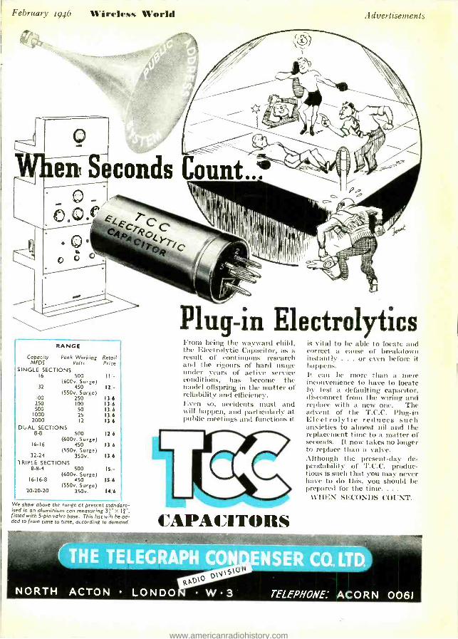
February 1946 Wireless World Advertisements
RANGE
Capacity Peak Working MFDS Volts
SINGLE SECTIONS 16 500
(600v. Surge) 32 450
(550v. Surge) 100 250 250 100 500 50
1000 25 2000 12
DUAL SECTIONS 8-8 500
(600v. Surge) 16 -16 450
(550v. Surge) 32 -24 350v.
TRIPLE SECTIONS 8 -8 -4 500
(600e. Surge) 16 -16 -8 450
(550v. Surge) 20 -20 -20 350v.
Retail Price
II -
12'-
13 6 136 136 136 136
126
136
13.6
IS,-
IS 6
14,6
We show above the ronge at present standard- ised in an aluminium can measuring 3r>: fitted with 5 -pin valve base. This list will be ad- ded to from time to time, according to demand.
Plug -in Electrolytics From being the wayward child, the Electrolytic Capacitor, as a result of continuous research and the rigours of hard usage under years of active service conditions, has become the model offspring in the matter of reliability and efficiency. Even so, accidents must and will happen. and particularly at public tileetinurs and functions it
CAPACITORS
is vital to be able to locate and correct a cause of breakdown instantly . .. or even before it happens. It can be more than a mere inconvenience to have to locate by test a defaulting capacitor, disconnect from the wiring and replace with a new one. The advent of the T.C.C. Plug -in Electrolytic reduces such anxieties to almost nil and the replacement time to a matter of seconds. It now takes no longer to replace than a valve. Although the present -day de- pendability of T.C.C. produc- tions is such that you may never have to do this, you should be prepared for the time...
WHEN SECONDS COUNT.
www.americanradiohistory.com

Advertisements Wfirre_an Id February 1946
THE MOST FAMOUS SET MAKERS ARE AGAIN FITTING
MAZDA RADIO VALVES AND
CATHODE RAY TUBES
because of their
PERFORMANCE AND
RELIABILITY
CHARACTERISTIC CURVES OF AVERAGE
MAZDA VALVE VP.23 (CURVES TAKEN AT Va= 120 VOLTS)
1
t
ti M ,NQ
1111111111.P.-
,A
GRID
5
z
D U
O O !iiP, VOLTS
3
THE FILAMENT CURRENT OF
THE MAZDA VP 23 IS
EXCEPTIONALLY LOW; IT IS
ONLY 50mA.
ITS MUTUAL CONDUCTANCE (9m -1.3mA /V) IS REMARKABLY
2 HIGH FOR A VALVE HAVING SO LOW A FILAMENT CONSUMPTION.
THIS VALVE MAY BE USED
AS A REPLACEMENT IN THE
CIVILIAN WAR -TIME RADIO
RECEIVER.
-20 -18 -16 -14 -12 -10 -8 -6 -4 -2 0
THE EDISON SWAN ELECTRIC COMPANY LIMITED 7 155, CHARING CROSS ROAD, LONDON, W.C.2
www.americanradiohistory.com