Anchored Blind Bolted Connections within SHS Concrete ... · PDF fileAnchored Blind Bolted...
9
Australian Earthquake Engineering Society 2011 Conference, Novotel Barossa Valley Resort, South Australia Anchored Blind Bolted Connections within SHS Concrete Filled Columns: Group performance Hossein Agheshlui 1 , Huang Yao 2 , Helen M. Goldsworthy 3 , Emad F. Gad 4 , Saman Fernando 5 1. Corresponding Author. PhD Student, Department of Infrastructure Engineering, The University of Melbourne, Parkville, Vic 3010. Email: [email protected] 2. Research Fellow, Department of Infrastructure Engineering, The University of Melbourne, Parkville, Vic 3010. Email: [email protected] 3. Senior Lecturer, Department of Infrastructure Engineering, The University of Melbourne, Parkville, Vic 3010. Email: [email protected] 4. Professor, Faculty of Engineering and Industrial Sciences, Swinburne University of Technology, Hawthorn, Vic 3122. Email: [email protected] 5. Engineering, R&D Manager, Ajax Engineered Fasteners, Braeside, Vic 3195. Email: [email protected] Abstract Concrete filled tubes are suitable choices for columns of low to medium rise commercial buildings. However, lack of access to the inner surface of these sections prevents connections with conventional bolts. To overcome this problem, blind bolts that can be installed only from one side can be used. A new type of blind bolt, the headed stud anchored blind bolt, has been developed at the University of Melbourne in collaboration with Ajax Fasteners. This type of blind bolt, in addition to bearing on the tube wall, is anchored in the infill concrete which results in improved stiffness and strength when it is subjected to tensile force. The pull-out behaviour and strength of headed stud anchored blind bolts as individuals or groups of two and three are studied in this research. The study shows that the tension connections made using groups of blind bolts potentially have sufficed strength and stiffness to be used in moment resisting connections within low to medium rise buildings in low to moderate seismic areas such as Australia. Keywords: Headed stud anchored blind bolt, group action, load-displacement behaviour
Transcript of Anchored Blind Bolted Connections within SHS Concrete ... · PDF fileAnchored Blind Bolted...

Australian Earthquake Engineering Society 2011 Conference, Novotel Barossa Valley Resort, South Australia
Anchored Blind Bolted Connections within SHS Concrete Filled Columns: Group performance
Hossein Agheshlui1, Huang Yao2, Helen M. Goldsworthy3, Emad F. Gad4 ,
Saman Fernando5
1. Corresponding Author. PhD Student, Department of Infrastructure Engineering, The University of Melbourne, Parkville, Vic 3010. Email: [email protected] 2. Research Fellow, Department of Infrastructure Engineering, The University of Melbourne, Parkville, Vic 3010. Email: [email protected] 3. Senior Lecturer, Department of Infrastructure Engineering, The University of Melbourne, Parkville, Vic 3010. Email: [email protected] 4. Professor, Faculty of Engineering and Industrial Sciences, Swinburne University of Technology, Hawthorn, Vic 3122. Email: [email protected] 5. Engineering, R&D Manager, Ajax Engineered Fasteners, Braeside, Vic 3195. Email: [email protected]
Abstract Concrete filled tubes are suitable choices for columns of low to medium rise commercial buildings. However, lack of access to the inner surface of these sections prevents connections with conventional bolts. To overcome this problem, blind bolts that can be installed only from one side can be used. A new type of blind bolt, the headed stud anchored blind bolt, has been developed at the University of Melbourne in collaboration with Ajax Fasteners. This type of blind bolt, in addition to bearing on the tube wall, is anchored in the infill concrete which results in improved stiffness and strength when it is subjected to tensile force. The pull-out behaviour and strength of headed stud anchored blind bolts as individuals or groups of two and three are studied in this research. The study shows that the tension connections made using groups of blind bolts potentially have sufficed strength and stiffness to be used in moment resisting connections within low to medium rise buildings in low to moderate seismic areas such as Australia. Keywords: Headed stud anchored blind bolt, group action, load-displacement behaviour
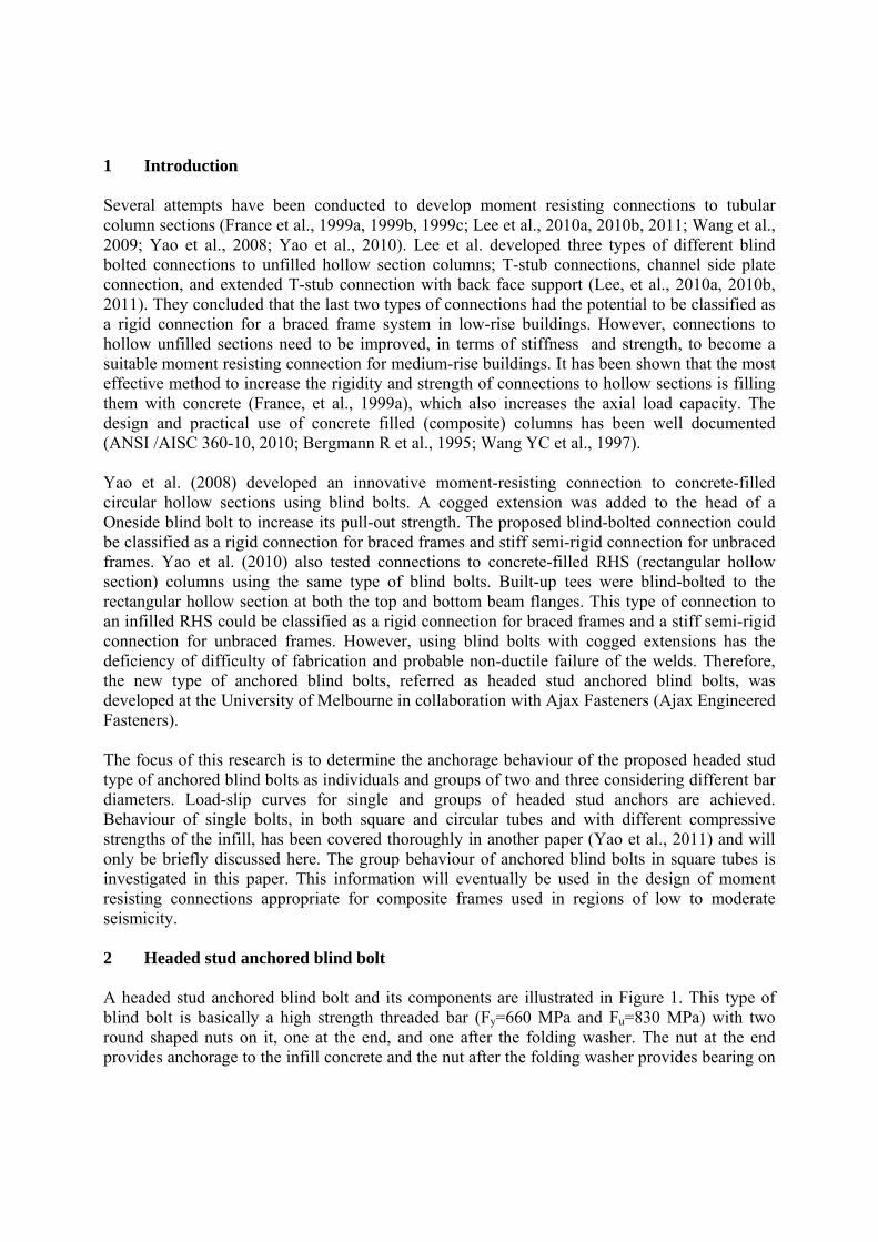
1 Introduction Several attempts have been conducted to develop moment resisting connections to tubular column sections (France et al., 1999a, 1999b, 1999c; Lee et al., 2010a, 2010b, 2011; Wang et al., 2009; Yao et al., 2008; Yao et al., 2010). Lee et al. developed three types of different blind bolted connections to unfilled hollow section columns; T-stub connections, channel side plate connection, and extended T-stub connection with back face support (Lee, et al., 2010a, 2010b, 2011). They concluded that the last two types of connections had the potential to be classified as a rigid connection for a braced frame system in low-rise buildings. However, connections to hollow unfilled sections need to be improved, in terms of stiffness and strength, to become a suitable moment resisting connection for medium-rise buildings. It has been shown that the most effective method to increase the rigidity and strength of connections to hollow sections is filling them with concrete (France, et al., 1999a), which also increases the axial load capacity. The design and practical use of concrete filled (composite) columns has been well documented (ANSI /AISC 360-10, 2010; Bergmann R et al., 1995; Wang YC et al., 1997). Yao et al. (2008) developed an innovative moment-resisting connection to concrete-filled circular hollow sections using blind bolts. A cogged extension was added to the head of a Oneside blind bolt to increase its pull-out strength. The proposed blind-bolted connection could be classified as a rigid connection for braced frames and stiff semi-rigid connection for unbraced frames. Yao et al. (2010) also tested connections to concrete-filled RHS (rectangular hollow section) columns using the same type of blind bolts. Built-up tees were blind-bolted to the rectangular hollow section at both the top and bottom beam flanges. This type of connection to an infilled RHS could be classified as a rigid connection for braced frames and a stiff semi-rigid connection for unbraced frames. However, using blind bolts with cogged extensions has the deficiency of difficulty of fabrication and probable non-ductile failure of the welds. Therefore, the new type of anchored blind bolts, referred as headed stud anchored blind bolts, was developed at the University of Melbourne in collaboration with Ajax Fasteners (Ajax Engineered Fasteners). The focus of this research is to determine the anchorage behaviour of the proposed headed stud type of anchored blind bolts as individuals and groups of two and three considering different bar diameters. Load-slip curves for single and groups of headed stud anchors are achieved. Behaviour of single bolts, in both square and circular tubes and with different compressive strengths of the infill, has been covered thoroughly in another paper (Yao et al., 2011) and will only be briefly discussed here. The group behaviour of anchored blind bolts in square tubes is investigated in this paper. This information will eventually be used in the design of moment resisting connections appropriate for composite frames used in regions of low to moderate seismicity. 2 Headed stud anchored blind bolt A headed stud anchored blind bolt and its components are illustrated in Figure 1. This type of blind bolt is basically a high strength threaded bar (Fy=660 MPa and Fu=830 MPa) with two round shaped nuts on it, one at the end, and one after the folding washer. The nut at the end provides anchorage to the infill concrete and the nut after the folding washer provides bearing on
the tubesolid wbears oanchoreand 20 diamete
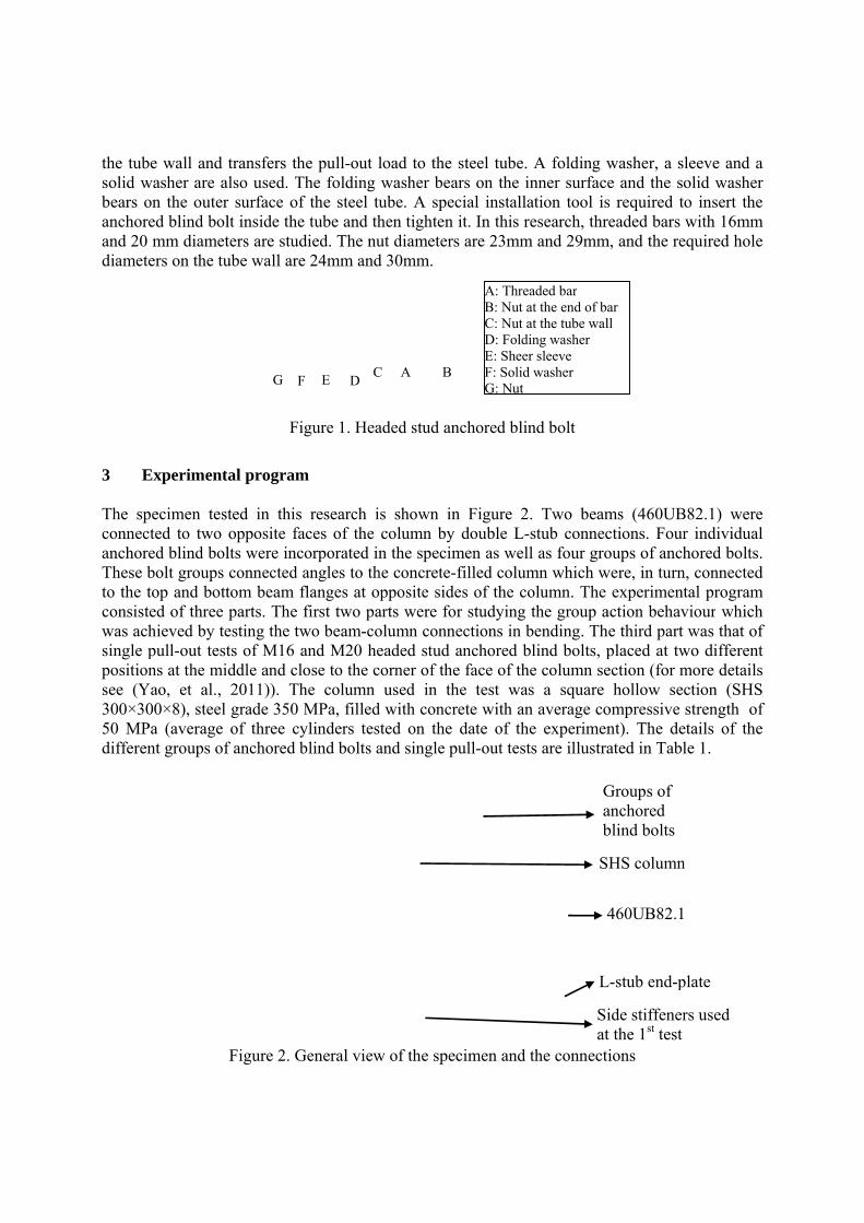
3 E The spconnectanchoreThese bto the toconsistewas achsingle ppositionsee (Ya300×3050 MPadifferen
e wall and washer are a
n the outered blind bolmm diamet
ers on the tu
Experiment
ecimen testted to two ed blind bolbolt groups op and botted of three hieved by tepull-out testns at the miao, et al.,
00×8), steel a (average nt groups of
transfers thlso used. T
r surface of lt inside theters are studube wall are
Fi
al program
ted in this opposite falts were incconnected atom beam fparts. The f
esting the twts of M16 addle and clo2011)). Thgrade 350 Mof three cy
f anchored b
Figure 2. G
FG
he pull-out lThe folding f the steel tue tube and thdied. The nue 24mm and
gure 1. Hea
m
research iaces of the orporated inangles to thflanges at opfirst two pawo beam-coand M20 heose to the che column MPa, filledylinders tesblind bolts a
General view
CDE F
load to the washer beaube. A spechen tighten ut diametersd 30mm.
aded stud an
s shown incolumn by n the specim
he concrete-pposite side
arts were foolumn conneaded stud aorner of theused in th
d with concrted on the
and single p
w of the spe
A BC
steel tube. ars on the incial installait. In this re
s are 23mm
nchored blin
n Figure 2.double L-s
men as wellfilled columes of the cor studying tections in banchored be face of thehe test wasrete with andate of the
pull-out tests
cimen and t
A: ThreaB: Nut aC: Nut aD: FoldiE: SheerF: Solid G: Nut
A folding wnner surfaceation tool isesearch, thr
m and 29mm
nd bolt
. Two beamstub connecl as four gromn which wolumn. The the group a
bending. Thlind bolts, pe column ses a square n average coe experimens are illustra
the connect
aded bar at the end of baat the tube walng washer
r sleeve washer
L
4
Gab
Siat
S
washer, a se and the ss required treaded bars
m, and the re
ms (460UBctions. Fouroups of anch
were, in turnexperiment
action behavhe third part placed at twection (for m
hollow seompressive nt). The deated in Tabl
ions
ar ll
L-stub end-p
460UB82.1
Groups of anchored blind bolts
ide stiffenert the 1st test
HS column
leeve and aolid washerto insert thewith 16mm
equired hole
B82.1) werer individualhored bolts
n, connectedtal programviour whichwas that of
wo differentmore detailsction (SHSstrength of
etails of thele 1.
plate
rs used
n
a r e
m e
e l .
d m h f t s S f e
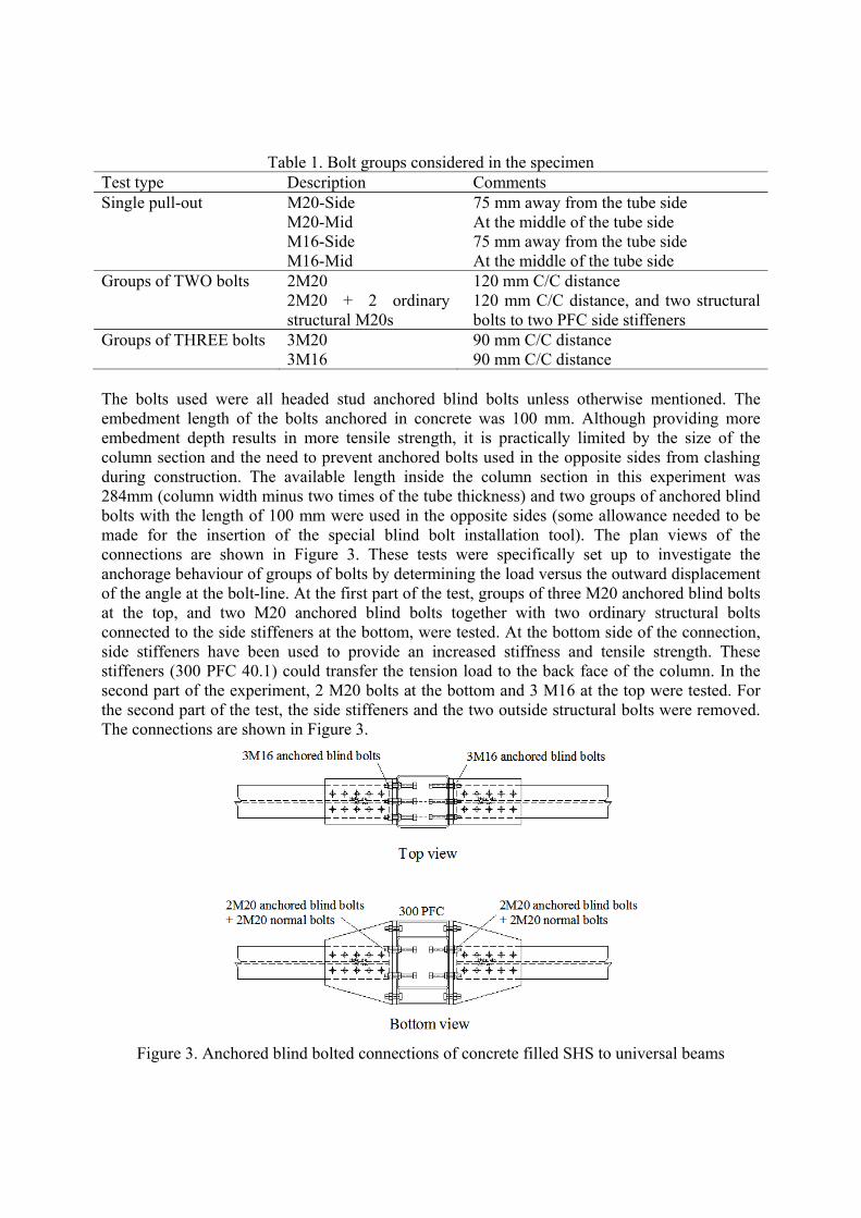
Table 1. Bolt groups considered in the specimen Test type Description Comments Single pull-out M20-Side 75 mm away from the tube side
M20-Mid At the middle of the tube side M16-Side 75 mm away from the tube side M16-Mid At the middle of the tube side
Groups of TWO bolts 2M20 120 mm C/C distance 2M20 + 2 ordinary
structural M20s 120 mm C/C distance, and two structural bolts to two PFC side stiffeners
Groups of THREE bolts 3M20 90 mm C/C distance 3M16 90 mm C/C distance The bolts used were all headed stud anchored blind bolts unless otherwise mentioned. The embedment length of the bolts anchored in concrete was 100 mm. Although providing more embedment depth results in more tensile strength, it is practically limited by the size of the column section and the need to prevent anchored bolts used in the opposite sides from clashing during construction. The available length inside the column section in this experiment was 284mm (column width minus two times of the tube thickness) and two groups of anchored blind bolts with the length of 100 mm were used in the opposite sides (some allowance needed to be made for the insertion of the special blind bolt installation tool). The plan views of the connections are shown in Figure 3. These tests were specifically set up to investigate the anchorage behaviour of groups of bolts by determining the load versus the outward displacement of the angle at the bolt-line. At the first part of the test, groups of three M20 anchored blind bolts at the top, and two M20 anchored blind bolts together with two ordinary structural bolts connected to the side stiffeners at the bottom, were tested. At the bottom side of the connection, side stiffeners have been used to provide an increased stiffness and tensile strength. These stiffeners (300 PFC 40.1) could transfer the tension load to the back face of the column. In the second part of the experiment, 2 M20 bolts at the bottom and 3 M16 at the top were tested. For the second part of the test, the side stiffeners and the two outside structural bolts were removed. The connections are shown in Figure 3.
Figure 3. Anchored blind bolted connections of concrete filled SHS to universal beams

3.1. Experimental setup and instrumentation A gravity load of 800KN (about 20% of the composite column axial capacity) was applied under load control at the top of the column. The vertical loading was done at the beginning of the test using a load cell which was fixed to the reaction frame. A hydraulic actuator was used to apply a vertical cyclic load at the cantilever end of the beam. The concrete filled SHS column was restrained at both ends and was tied down to the laboratory strong floor directly at the bottom and using four braces at the top. For both connection tests eleven displacement transducers (LVDTs) were used to measure the beam end deflection, slip between the beam and the L-stub, the pull-out of the bolts and the shear deflection of the L-stubs. The description of measurements made by each of the LVDTs is listed in Table 2. Photos of the LVDTs are also shown in Figure 4. For the first connection test, 23 strain gauges and for the second one 15 strain gauges were used to monitor strains occurring on L-stubs, stiffeners, tube wall, and beams.
Table 2. Description of the measurements by LVDTs LVDT No. Description of the measurements by LVDTs 1 and 6 Total deflection of the top and bottom angles along the beam axis 2 and 7 Slip between the angle and the beam at the top and the bottom 3 and 8* Bolt pull-out plus angle flexural deflection at the top and the bottom4 and 9 Angle flexural deflection at the top and the bottom 5 and 10 Shear deflection of the top and bottom angles 11 Vertical displacement of the beam end
* Bolt net outward displacement can be found by deducting readings of No.4 (9) from No. 3 (8)
Figure 4. Arrangment of the LVDTs used for monitoring the specimen’s movement
Digital photogrammetry, a three-dimensional coordinate measuring technique with accuracy of 0.03 mm, was also employed in this test. An initial photogrammetry survey recorded the original coordinates of the targets just prior to loading. Subsequent surveys were taken at the end of the first cycle of each load step to record the new coordinates of the targets. By analysing consecutive overlapping photographs at each load increment, the three dimensional topographic information for the specimen can be established for each photogrammetry target. Photogrammetry targets were placed on the column, T-stubs, stiffeners and the beam to obtain the overall deformation profile. Some of the photogrammetry targets used in the experiment can be seen in Figure 2 and Figure 4.
2
1
34
6
7
89
10
5

3.2. Load protocol The beam-column connections were tested under asymmetrical cyclic loading due to the different estimated capacities and stiffnesses for the top and bottom angles. The headed stud anchored blind bolt is a new type of connector and a theoretical prediction of the elastic limit and the ultimate load capacity of the groups of these types of bolts were not available before the test (this is the subject of a current detailed analytical study). For the purpose of the tests it was necessary to predict the expected values of the elastic limit and the ultimate load capacity in order to design the initial load protocol which was updated during the test based on the observed behaviour. In the previous single pull-out tests (Yao, et al., 2011), it was observed that pull-out strength of anchored blind bolts located at the corner of the face of a column section reached to the maximum capacity of the bolts, even when the concrete with lower compressive strength was used. Hence, for calculation of the ultimate capacity of the groups of anchored blind bolts, the maximum tensile capacity of the bolts was multiplied by the strength reduction factor (=0.8 according to (AS 4100, 1998)) and group reduction factor (assumed 0.85) for the first connection. However, the observed ultimate and serviceability loads from this test were higher than the predicted values and they were close to the maximum predicted load without considering any reduction factors. Thus, to spread the load cycles more evenly in the whole load range of the second connection test, no reduction factor was implemented in the calculations. For the serviceability load limit, two third of the ultimate capacity of the anchored blind bolts was adopted. These load values used for testing the specimen are presented in Table 3. Five load steps, each with three cycles, were applied in the serviceability range and four load steps, each with two cycles, were applied in the inelastic range. Then the load was increased until the failure was reached. The loading was applied as displacement control except for the very first load steps.
Table 3. The ultimate and serviceability load limits used in the experiment Bolt group Ultimate load capacity
used in load protocol Serviceability load capacity
used in load protocol 3 M20 (3×203)(0.8)(0.85) ≈ 400KN (2/3)(400) ≈ 260KN
2 M20 + 2 structural M20s
(4×203)(0.8)(0.85) ≈ 560KN (2/3)(560) ≈ 380KN
2 M20 (2×203) ≈ 400KN (2/3)(400) ≈ 260KN 3 M16 (3×130) ≈ 390KN (2/3)(400) ≈ 260KN
4 Experimental results 4.1. Pull-out behaviour of individual headed stud anchored blind bolts The load-outward displacement curves for pull-out tests of individual headed stud anchored blind bolts are shown in Figure 5. The instrumentation for measuring the outward displacements of the bolts and discussion about the pull-out behaviour is presented in Yao, et al. (2011). Failure of the all of the anchored blind bolts commenced with concrete cone failure which was then followed by either bolt tensile failure or tube yielding around the bolt hole.

4.2. B In Figuraxis of calculatnumberload on
In Figurtwo andof comp2M20 b
olt group b
re 6, load-slthe diagramted by dedur 9 from num
n the angles
Figure 5. L
re 6, the pud three for Mparison of bolts is abo
behaviour
lip behavioum displays tucting meamber 8 for tproduced b
Load- dispa
Figure
ull-out strengM20 and byindividual
out two tim
ur for the grthe net outwasurements the bottom
by the mome
acement cur
6. Load-out
gth of a siny two for Mand group
mes of the p
roups of anward displaof LVDT angles at thent applied
rve for pull-
tward displa
gle M20-Si16, are showbehaviour.
pull-out cap
chored blinacement of t
number 4 he connectioto the conn
out headed
acement of
ide and a sinwn as dasheAs it can
pacity of a
nd bolts is dethe angle atfrom numb
ons. The verection.
stud anchor
bolt groups
ngle M16-Sed lines andbe seen, thsingle M20
epicted. Thet the bolt-linber 3 for trtical axis is
red blind bo
s
Side, also md can be usehe ultimate 0. This me
e horizontalne which isthe top ands the tensile
olts
multiplied byed as a basiscapacity ofans that no
l s d e
y s f o
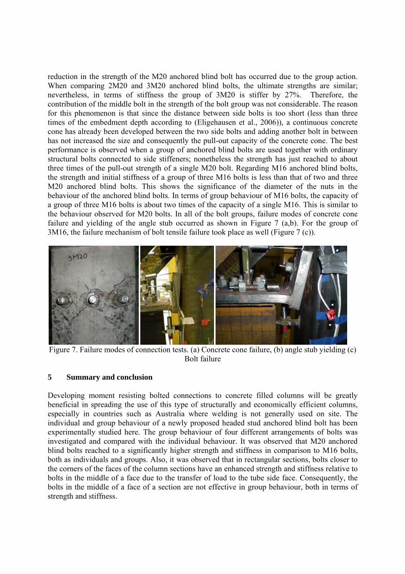
reduction in the strength of the M20 anchored blind bolt has occurred due to the group action. When comparing 2M20 and 3M20 anchored blind bolts, the ultimate strengths are similar; nevertheless, in terms of stiffness the group of 3M20 is stiffer by 27%. Therefore, the contribution of the middle bolt in the strength of the bolt group was not considerable. The reason for this phenomenon is that since the distance between side bolts is too short (less than three times of the embedment depth according to (Eligehausen et al., 2006)), a continuous concrete cone has already been developed between the two side bolts and adding another bolt in between has not increased the size and consequently the pull-out capacity of the concrete cone. The best performance is observed when a group of anchored blind bolts are used together with ordinary structural bolts connected to side stiffeners; nonetheless the strength has just reached to about three times of the pull-out strength of a single M20 bolt. Regarding M16 anchored blind bolts, the strength and initial stiffness of a group of three M16 bolts is less than that of two and three M20 anchored blind bolts. This shows the significance of the diameter of the nuts in the behaviour of the anchored blind bolts. In terms of group behaviour of M16 bolts, the capacity of a group of three M16 bolts is about two times of the capacity of a single M16. This is similar to the behaviour observed for M20 bolts. In all of the bolt groups, failure modes of concrete cone failure and yielding of the angle stub occurred as shown in Figure 7 (a,b). For the group of 3M16, the failure mechanism of bolt tensile failure took place as well (Figure 7 (c)).
Figure 7. Failure modes of connection tests. (a) Concrete cone failure, (b) angle stub yielding (c)
Bolt failure 5 Summary and conclusion Developing moment resisting bolted connections to concrete filled columns will be greatly beneficial in spreading the use of this type of structurally and economically efficient columns, especially in countries such as Australia where welding is not generally used on site. The individual and group behaviour of a newly proposed headed stud anchored blind bolt has been experimentally studied here. The group behaviour of four different arrangements of bolts was investigated and compared with the individual behaviour. It was observed that M20 anchored blind bolts reached to a significantly higher strength and stiffness in comparison to M16 bolts, both as individuals and groups. Also, it was observed that in rectangular sections, bolts closer to the corners of the faces of the column sections have an enhanced strength and stiffness relative to bolts in the middle of a face due to the transfer of load to the tube side face. Consequently, the bolts in the middle of a face of a section are not effective in group behaviour, both in terms of strength and stiffness.
(a) (b) (c)

Acknowledgements This research program is a part of a research project supported by Australian Research Council, Ajax Engineered Fasteners, and Australian Tube Mills through Linkage Project No. LP0669334. The generous contributions of these three research and industry partners are greatly appreciated.
References:
Ajax Engineered Fasteners. Available: http://www.ajaxfast.com.au/,. ANSI /AISC 360-10. (2010). Specification for Structural Steel Buildings. Chicago, Illinois: AMERICAN INSTITUTE OF STEEL CONSTRUCTION. AS 4100. (1998). Australian Standard- Steel structures: STANDARDS AUSTRALIA. Bergmann R, Matsui C, Meinsma C, & D, D. (1995). Design guide for concrete filled hollow section columns under static and seismic loading. Verlag TÜV Rheinland, Koln: CIDECT. Eligehausen, R., Mallée, R., & Silva, J. F. (2006). Anchorage in concrete construction: Ernst & Sohn. France, J. E., Buick Davison, J., & A. Kirby, P. (1999a). Moment-capacity and rotational stiffness of endplate connections to concrete-filled tubular columns with flowdrilled connectors. Journal of Constructional Steel Research, 50(1), 35-48. France, J. E., Buick Davison, J., & A. Kirby, P. (1999b). Strength and rotational response of moment connections to tubular columns using flowdrill connectors. Journal of Constructional Steel Research, 50(1), 1-14. France, J. E., Buick Davison, J., & A. Kirby, P. (1999c). Strength and rotational stiffness of simple connections to tubular columns using flowdrill connectors. Journal of Constructional Steel Research, 50(1), 15-34. Lee, J., Goldsworthy, H. M., & Gad, E. F. (2010a). Blind bolted side connection for unfilled hollow section columns. Paper presented at the 21st Australasian conference on the mechanics of structures and materials (ACMSM21). Lee, J., Goldsworthy, H. M., & Gad, E. F. (2010b). Blind bolted T-stub connections to unfilled hollow section columns in low rise structures. Journal of Constructional Steel Research, 66(8-9), 981-992. Lee, J., Goldsworthy, H. M., & Gad, E. F. (2011). Blind bolted moment connection to unfilled hollow section columns using extended T-stub with back face support. Engineering Structures, 33(5), 1710-1722. Wang, J.-F., Han, L.-H., & Uy, B. (2009). Behaviour of flush end plate joints to concrete-filled steel tubular columns. Journal of Constructional Steel Research, 65(4), 925-939. Wang YC, & Moore DB. (1997). A design method for concrete-filled, hollow section, composite columns. Journal of the Institution of Structural Engineers, 75(21), 368–373. Yao, H., Goldsworthy, H., & Gad, E. (2008). Experimental and Numerical Investigation of the Tensile Behaviour of Blind-Bolted T-Stub Connections to Concrete-Filled Circular Columns. JOURNAL OF STRUCTURAL ENGINEERING, 134(2), 198-208. Yao, H., Goldsworthy, H., & Gad, E. (2010). Structural behaviour of beam-to-RHS column connection with blind bolts Incorporating Sustainable Practice in Mechanics and Structures of Materials (pp. 53-58): CRC Press. Yao, H., Goldsworthy, H., Gad, E., & Fernando, S. (2011). Experimental Study on Modified Blind Bolts Anchored in Concrete-filled Steel Tubular Columns. Paper presented at the Submitted to Australian Earthquake Engineering Society 2011 Conference.