Anchorage of Shear Reinforcement in Prestressed Concrete Bridge ...
24
Anchorage of Shear Reinforcement in Prestressed Concrete Bridge Girders Brian Mathys – RA Catherine French – PI Carol Shield – Co-PI Department of Civil Engineering CTS 2014 Research Conference 5/21/14
Transcript of Anchorage of Shear Reinforcement in Prestressed Concrete Bridge ...

Anchorage of Shear Reinforcement in Prestressed Concrete Bridge Girders
Brian Mathys – RA Catherine French – PI Carol Shield – Co-PI
Department of Civil Engineering
CTS 2014 Research Conference 5/21/14

Presentation Outline • Background • Objective • Subassemblage Tests • Girder Tests • Conclusions
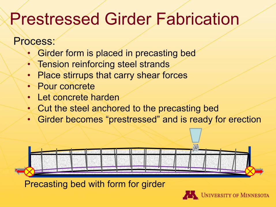
Prestressed Girder Fabrication Process:
• Girder form is placed in precasting bed • Tension reinforcing steel strands • Place stirrups that carry shear forces • Pour concrete • Let concrete harden • Cut the steel anchored to the precasting bed • Girder becomes “prestressed” and is ready for erection
Precasting bed with form for girder

Loading of PC Girder
Concrete deck
Stirrups Abutment
creates Shear Forces
• Resistance provided by: • Transverse reinforcement contribution • Concrete contribution
Load must travel to abutment
Girder top flange
Girder web
Girder bottom flange
Prestressing steel

Transverse Reinforcement Contribution • Tension forces in the stirrups require:
– Adequate anchorage & development of stirrups in bottom flange where prestressing compression helps
Anchor & develop stirrups in bottom flange
Straight Leg Stirrups vs.
Hooked Leg Stirrups
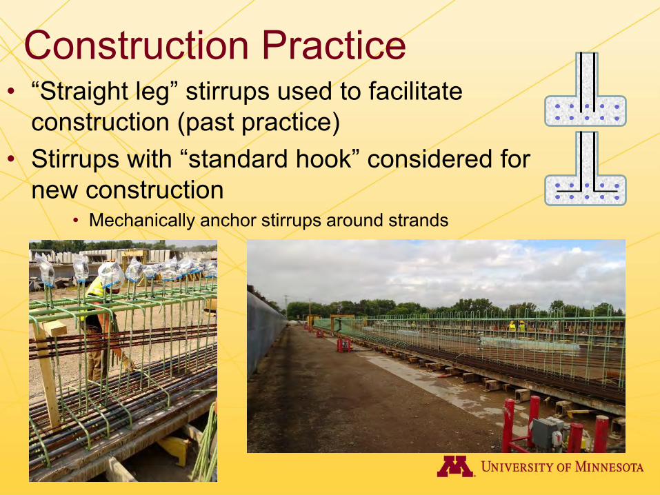
• “Straight leg” stirrups used to facilitate construction (past practice)
• Stirrups with “standard hook” considered for new construction
• Mechanically anchor stirrups around strands
Construction Practice

Objectives • Investigate the effectiveness of straight-
legged stirrup anchorage in developing yield

Subassemblage Test Specimens
• Shape (Embedment length) – M and MN – 7 in. to 9 in. embedment
• Precompression – 0.01∙fc’ and 0.45∙fc’
• Presence or absence of confinement steel • Concrete strength
– 6.4 ksi to 9.5 ksi
Epoxy Coated
M MN

Full-Scale Girder Tests • Nominal fc’ = 7.5 ksi • Girder depth
– 36 in. and 45 in. • Nominal anchorage length
– 8 in. anchorage for M shape – 6-¾ in. including tolerances
• Flexure-shear vs web-shear • Stirrup spacing
– s = 18 in. for flexure-shear – s = 8 or 24 in. for web-shear

Stirrup Spacing • Tight Spacing
– Group effect reduces anchorage strength • Wide Spacing
– Fewer stirrups crossed by cracks
Greater effecting anchorage likely
Stirrups with limited anchorage resist shear

Prestressing • Relatively high number of strands
– Provides flexural resistance – Varying levels of strand stress levels
• Prestress of 0.40∙fc’ targeted – Achieved 0.23∙fc’ in 36M – Achieved 0.30∙fc’ in 45M – Cast on a single bed
Straight Strands: X - 0.1∙fpu • - 0.60∙fpu • - Debonded
Draped Strands: • - 0.43∙fpu

Test Setup • Flexure-shear test
– 2 concentrated loads • 220-kip actuator at midspan • 110-kip actuator 40 in. closer
to the support
• Web-shear test – 1 concentrated load
• 600-kip MTS test machine • a/d ratio ≈ 2.3-2.5
110 kip 220 kip
600 kip 600 kip
600 kip
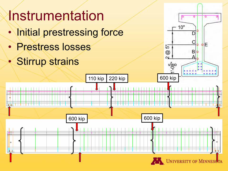
Instrumentation • Initial prestressing force • Prestress losses • Stirrup strains
110 kip 220 kip
600 kip 600 kip
600 kip

Flexure-Shear Test Results • Flexural cracks occurred at stirrup locations prior to
shear cracking • Yield strains exceeded • Maximum applied load limited to flexural capacity

45M
45M
Web-Shear Test Results • Strains exceeding yield measured throughout failure regions
36M
Gage Location Yield Strain Exceeded Residual Crack
643 kip
360 kip
558 kip
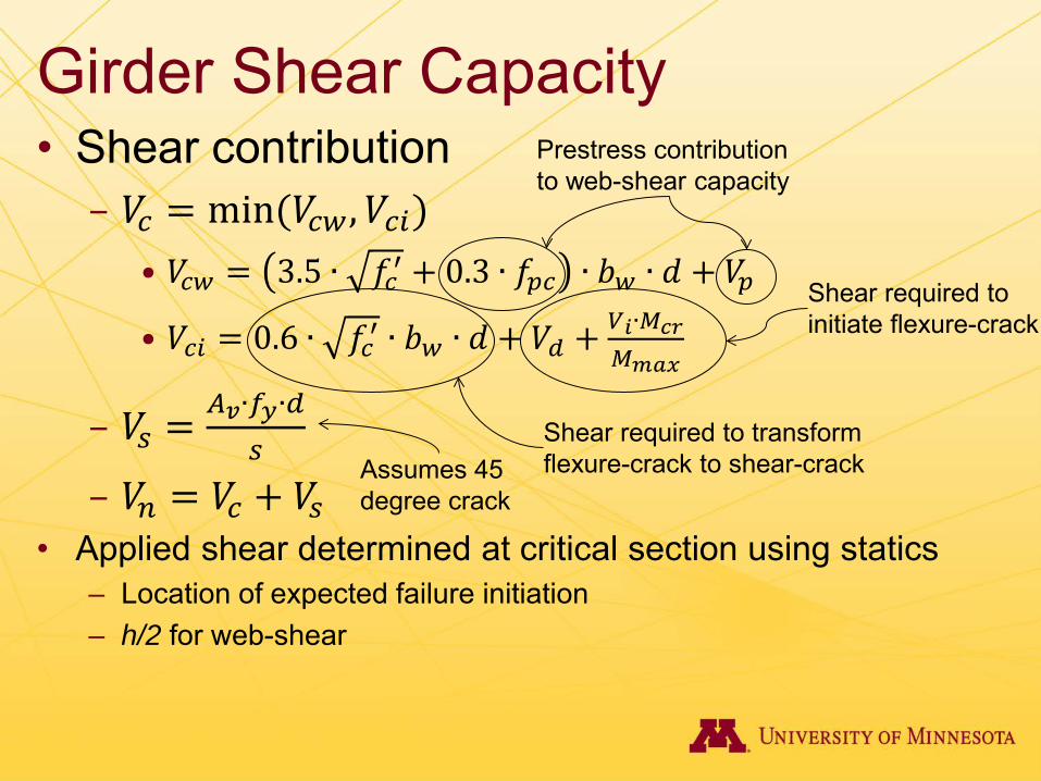
Girder Shear Capacity • Shear contribution
– 𝑉𝑐 = min (𝑉𝑐𝑐,𝑉𝑐𝑐) • 𝑉𝑐𝑐 = 3.5 ∙ 𝑓𝑐′ + 0.3 ∙ 𝑓𝑝𝑐 ∙ 𝑏𝑐 ∙ 𝑑 + 𝑉𝑝
• 𝑉𝑐𝑐 = 0.6 ∙ 𝑓𝑐′ ∙ 𝑏𝑐 ∙ 𝑑 + 𝑉𝑑 + 𝑉𝑖∙𝑀𝑐𝑐𝑀𝑚𝑚𝑚
– 𝑉𝑠 = 𝐴𝑣∙𝑓𝑦∙𝑑𝑠
– 𝑉𝑛 = 𝑉𝑐 + 𝑉𝑠 • Applied shear determined at critical section using statics
– Location of expected failure initiation – h/2 for web-shear
Shear required to initiate flexure-crack
Shear required to transform flexure-crack to shear-crack Assumes 45
degree crack
Prestress contribution to web-shear capacity

Shear Distribution at Failure
36M – Flexure-shear test
108 kip 216 kip
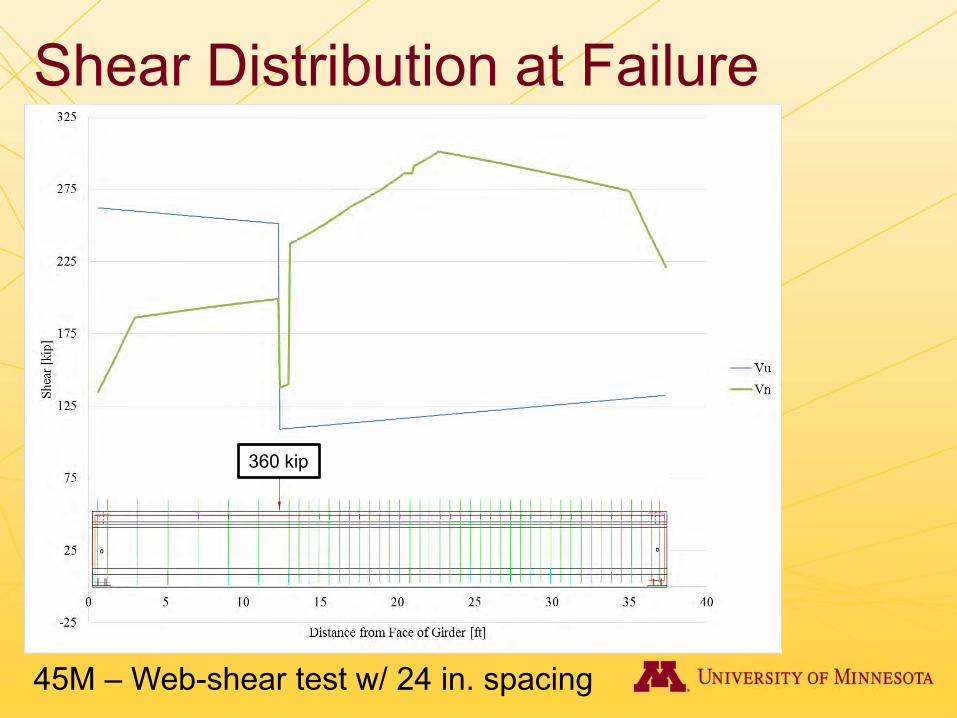
Shear Distribution at Failure
45M – Web-shear test w/ 24 in. spacing
360 kip
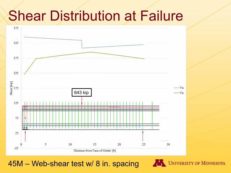
Shear Distribution at Failure
45M – Web-shear test w/ 8 in. spacing
643 kip
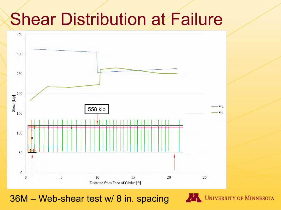
Shear Distribution at Failure
36M – Web-shear test w/ 8 in. spacing
558 kip

Girder Capacities • Nominal shear capacities exceeded at critical section
Test Specimen Vmax,test
[kip]
Vn
[kip] Vmax/Vn
Vcw,test
[kip]
Vcw @ h/2
[kip] Vcw,test/Vcw
36M_18F 174 141 1.23 112 102 1.09
45M_24W 259 188 1.38 166 139 1.20
45M_8W 343 288 1.19 162 140 1.16
36M_8W 311 230 1.35 114 104 1.09
Girder Test Conclusions • Stirrups yielded in all four static shear tests
– All three web-shear cases (45M_24W, 45M_8W, 36M_8W) and flexure-shear case (36M_18F)
• Anchorage depth
– Reduced anchorage depth did not inhibit ability to develop yield strains
• Shear capacity
– Nominal shear capacity exceeded by applied shear in each test by an average of 1.29

Acknowledgements • Staff
– Paul Bergson, Catherine French, Rachel Gaulke, Jane Govro, Carol Shield
• Graduate Students – Braden Cyr, Ben Dymond, Brock Hedgard, Kyle Hoegh, Ken Ito,
Cat Johnson, Dan Morten, Sam Paitich, Tanner Swenson, Meagan Young
• Research Assistants – Spencer Borchardt, Giovanni Dellwo, Anna Flintrop, Jake
Jeanquart, Melynda Jensen, Sam Konieczny, Veronica Kubicek, Mike Larson, Andrew Morgan, Mac Parris, Charles Vermace

Questions?