Anchor Fastening Technology Manual 09 / 2012 Fastening Technology Manuals for Post-installed Anchors...
25
10 / 2012 0 Anchor Fastening Technology Manual 09 / 2012
-
Upload
phungtuyen -
Category
Documents
-
view
214 -
download
1
Transcript of Anchor Fastening Technology Manual 09 / 2012 Fastening Technology Manuals for Post-installed Anchors...

10 / 20120
Anchor FasteningTechnology Manual
09 / 2012

Forword
10 / 2012 1
Foreword
Dear customer,
As it is our ambition to be the worldwide leader in fastening technology, we are continously striving to provide you with state-of-the-art technical information reflecting the latest developments in codes, regulations and approvals and technical information for our products.
The Fastening Technology Manuals for Post-installed Anchors and for Anchor Channel reflect our ongoing investment into long term research and development of leading fastening products.
This Fastening Technology Manual for Post-installed Anchors should be a valuable support tool for you when solving fastening tasks with Post-installed Anchor fastening technology. It should provide you with profound technical know-how, and help you to be more productive in your daily work without any compromise regarding reliability and safety.
As we strive to be a reliable partner for you, we would very much appreciate your feedback for improvements. We are available at any time to answer additional questions that even go beyond this content.
Raimund Zaggl
Business Unit Anchors

Important notices
10 / 20122
Important notices1. Construction materials and conditions vary on different sites. If it is suspected that the base
material has insufficient strength to achieve a suitable fastening, contact the Hilti Technical Advisory Service.
2. The information and recommendations given herein are based on the principles, formulae and safety factors set out in the Hilti technical instructions, the operating manuals, the setting instructions, the installation manuals and other data sheets that are believed to be correct at the time of writing. The data and values are based on the respective average values obtained from tests under laboratory or other controlled conditions. It is the users responsibility to use the data given in the light of conditions on site and taking into account the intended use of the products concerned. The user has to check the listed prerequisites and criteria conform with the conditions actually existing on the job-site. Whilst Hilti can give general guidance and advice, the nature of Hilti products means that the ultimate responsibility for selecting the right product for a particular application must lie with the customer.
3. All products must be used, handled and applied strictly in accordance with all current instructions for use published by Hilti, i.e. technical instructions, operating manuals, setting instructions, installation manuals and others.
4. All products are supplied and advice is given subject to the Hilti terms of business.
5. Hilti´s policy is one of continuous development. We therefore reserve the right to alter specifications, etc. without notice.
6. The given mean ultimate loads and characteristic data in the Anchor Fastening Technology Manual reflect actual test results and are thus valid only for the indicated test conditions. Due to variations in local base materials, on-site testing is required to determine performance at any specific site.
7. Hilti is not obligated for direct, indirect, incidental or consequential damages, losses or expenses in connection with, or by reason of, the use of, or inability to use the products for any purpose. Implied warranties of merchantability or fitness for a particular purpose are specifally excluded.
Hilti CorporationFL-9494 SchaanPrincipality of Liechtensteinwww.hilti.com
Hilti = registred trademark of the Hilti Corporation, Schaan

Contents
10 / 20124
Contents
Anchor technology and design ................................................................................................7
Anchor selector.....................................................................................................................................8
Legal environment ..............................................................................................................................20
Approvals ...........................................................................................................................................22
Base material .....................................................................................................................................28
Anchor design ....................................................................................................................................34
Design example..................................................................................................................................44
Corrosion............................................................................................................................................48
Dynamic loads (seismic, fatigue, shock) .............................................................................................52
Resistance to fire................................................................................................................................58
Mechanical anchoring systems ..............................................................................................71
HDA Design anchor............................................................................................................................72
HSL-3 carbon steel, heavy duty anchor ..............................................................................................88
HSL-GR stainless steel, heavy duty anchor......................................................................................100
HSC-A Safety anchor .......................................................................................................................110
HSC-I Safety anchor.........................................................................................................................120
HST Stud anchor ..............................................................................................................................130
HSA Stud anchor..............................................................................................................................140
HSV Stud anchor..............................................................................................................................160
HLC Sleeve anchor ..........................................................................................................................170
HAM Hard sleeve anchor..................................................................................................................176
HUS-HR Screw anchor, stainless steel.............................................................................................178
HUS Screw anchor, carbon steel ......................................................................................................194
HUS 6 Screw anchor, Redundant fastening......................................................................................210
HUS-A 6 / HUS-H 6 / HUS-I 6 / HUS-P 6 Screw anchor in precast prestressed hollow core slabs....218
HUS 6 / HUS-S 6 Screw anchor .......................................................................................................224
HKD Push-in anchor, Single anchor application................................................................................230
HKD Push-in anchor, Redundant fastening ......................................................................................244
HKV Push-in anchor, Single anchor application................................................................................252
HUD-1 Universal anchor...................................................................................................................256
HUD-L Universal anchor...................................................................................................................262
HLD Light duty anchor ......................................................................................................................266
HRD-U 10 / - S 10 / -U 14 Frame anchor ..........................................................................................270
HRD Frame anchor, Redundant fastening ........................................................................................276
HPS-1 Impact anchor .......................................................................................................................294
HHD-S Cavity anchor .......................................................................................................................298
HCA Coil anchor...............................................................................................................................300
HSP / HFP Drywall plug....................................................................................................................302
HA 8 Ring / hook anchor...................................................................................................................304
DBZ Wedge anchor ..........................................................................................................................308
HT Metal frame anchor .....................................................................................................................312
HK Ceiling anchor.............................................................................................................................316
HPD Aerated concrete anchor ..........................................................................................................322
HKH Hollow deck anchor..................................................................................................................328
HTB Hollow wall metal anchor ..........................................................................................................332
IDP Insulation fastener .....................................................................................................................336
IZ Insulation fastener ........................................................................................................................340
IDMS / IDMR Insulation fastener ......................................................................................................344
SPACIL
Highlight

Contents
10 / 2012 5
Adhesive anchoring systems ...............................................................................................349
HVZ Adhesive anchor.......................................................................................................................350
HVU with HAS/HAS-E rod adhesive anchor .....................................................................................362
HVU with HIS-(R)N adhesive anchor ................................................................................................372
Hilti HIT-RE 500-SD with HIT-V rod ..................................................................................................382
Hilti HIT-RE 500-SD with HIS-(R)N...................................................................................................398
Hilti HIT-RE 500-SD with rebar .........................................................................................................410
Hilti HIT-RE 500 with HIT-V / HAS in hammer drilled holes ..............................................................424
Hilti HIT-RE 500 with HIT-V / HAS in diamond drilled holes ..............................................................440
Hilti HIT-RE 500 with HIS-(R)N.........................................................................................................450
Hilti HIT-RE 500 with rebar in hammer drilled holes..........................................................................464
Hilti HIT-RE 500 with rebar in diamond drilled holes .........................................................................480
Hilti HIT-HY 200 with HIT-Z ..............................................................................................................490
Hilti HIT-HY 200 with HIT-V ..............................................................................................................510
Hilti HIT-HY 200 with HIS-(R)N.........................................................................................................528
Hilti HIT-HY 200 with rebar ...............................................................................................................544
Hilti HIT-HY 150 MAX with HIT-TZ....................................................................................................560
Hilti HIT-HY 150 MAX with HIT-V / HAS ...........................................................................................572
Hilti HIT-HY 150 MAX with HIS-(R)N ................................................................................................590
Hilti HIT-HY 150 MAX with rebar ......................................................................................................602
Hilti HIT-CT 1 with HIT-V ..................................................................................................................616
Hilti HIT-HY 150 with HIT-V / HAS....................................................................................................632
Hilti HIT-HY 150 with HIS-(R)N.........................................................................................................648
Hilti HIT-HY 150 with rebar ...............................................................................................................660
Hilti HIT-ICE with HIT-V / HAS..........................................................................................................674
Hilti HIT-ICE with HIS-(R)N...............................................................................................................686
Hilti HIT-ICE with rebar .....................................................................................................................698
Hilti HIT-HY 70 injection mortar for masonry.....................................................................................708
HRT-WH Rail anchor with Hilti HVU or Hilti HIT-RE 500...................................................................734
HRT Rail anchor with Hilti HIT-RE 500 .............................................................................................738
HRC / HRC-DB Rail anchor with Hilti HIT-RE 500 ............................................................................742
HRA Rail anchor with Hilti HIT-RE 500 or HVU-G/EA glass capsule.................................................746
HRT-I Rail anchor with Hilti HIT-RE 500 ...........................................................................................750
HRT-IP Rail Anchor for cast-in/top down construction method..........................................................754
Post-installed rebar connections .........................................................................................759
Basics, design and installation of post installed rebars .....................................................................760
Hilti HIT-RE 500-SD post-installed rebars.........................................................................................798
Hilti HIT-RE 500 post-installed rebars...............................................................................................810
Hilti HIT-HY 200 post-installed rebars...............................................................................................822
Hilti HIT-HY 150 post-installed rebars...............................................................................................830
Hilti HIT-HY 150 MAX post-installed rebars ......................................................................................838
Hilti worldwide........................................................................................................................848

HSC-A Safety anchor
10 / 2012110
HSC-A Safety anchorAnchor version Benefits
Bolt version
HSC-A Carbon Steel version
HSC-AR Stainless steel version
- the perfect solution for small edge and space distance
- suitable for thin concrete blocks due to low embedment depth
- suitable for cracked concrete- self-cutting undercut anchor - available as bolt version for
through applications- stainless steel available for
external applications
ConcreteTensile zone
Small edge distance
and spacing
Fire resistance Shock
Corrosion resistance
European Technical Approval
CE conformity
PROFIS Anchor design
software
Approvals / certificatesDescription Authority / Laboratory No. / date of issueEuropean technical approval a) CSTB, Paris ETA-02/0027 / 2007-09-20Shockproof fastenings in civil defence installations
Federal Office for Cicil Protection, Bern
BZS D 06-601 / 2006-07-10
Fire test report IBMB, Braunschweig UB 3177/1722-1 / 2006-06-28Assessment report (fire) warringtonfire WF 166402 / 2007-10-26
a) All data given in this section according ETA-02/0027 issue 2007-09-20
Basic loading dataAll data in this section applies to For details see Simplified design method- Correct setting (See setting instruction)- No edge distance and spacing influence- Concrete as specified in the table- Steel failure- Minimum base material thickness- Concrete C 20/25, fck,cube = 25 N/mm²

HSC-A Safety anchor
10 / 2012 111
Mean ultimate resistanceNon-cracked concrete Cracked concrete
Anchor size M8x40 M10x40 M8x50 M12x60 M8x40 M10x40 M8x50 ������
Tensile NRu,m
HSC-A
HSC-AR[kN] 16,6 16,6 23,3 30,6 13,3 13,3 18,6 24,5
Shear VRu,m
HSC-A [kN] 19,0 30,2 19,0 43,8 19,0 30,2 19,0 43,8
HSC-AR [kN] 16,6 26,4 16,6 38,4 16,6 26,4 16,6 38,4
Characteristic resistance Non-cracked concrete Cracked concrete
Anchor size M8x40 M10x40 M8x50 M12x60 M8x40 M10x40 M8x50 ������
Tensile NRk
HSC-A [kN] 12,8 12,8 17,8 23,4 9,1 9,1 12,7 16,7
HSC-AR [kN] 12,8 12,8 17,8 23,4 9,1 9,1 12,7 16,7
Shear VRk
HSC-A [kN] 14,6 23,2 14,6 33,7 14,6 18,2 14,6 33,5
HSC-AR [kN] 12,8 20,3 12,8 29,5 12,8 18,2 12,8 29,5
Design resistance Non-cracked concrete Cracked concrete
Anchor size M8x40 M10x40 M8x50 M12x60 M8x40 M10x40 M8x50 ������
Tensile NRd
HSC-A [kN] 8,5 8,5 11,9 15,6 6,1 6,1 8,5 11,2
HSC-AR [kN] 8,5 8,5 11,9 15,6 6,1 6,1 8,5 11,2
Shear VRd
HSC-A [kN] 11,7 17,0 11,7 27,0 11,7 12,1 11,7 22,3
HSC-AR [kN] 8,2 13,0 8,2 18,9 8,2 12,1 8,2 18,9
Recommended loads Non-cracked concrete Cracked concrete
Anchor size M8x40 M10x40 M8x50 M12x60 M8x40 M10x40 M8x50 ������
Tensile Nreca)
HSC-A [kN] 6,1 6,1 8,5 11,2 4,3 4,3 6,1 8,0
HSC-AR [kN] 6,1 6,1 8,5 11,2 4,3 4,3 6,1 8,0
Shear Vreca)
HSC-A [kN] 8,3 12,1 8,3 19,3 8,3 8,7 8,3 15,9
HSC-AR [kN] 5,9 9,3 5,9 13,5 5,9 8,7 5,9 13,5
a) With overall partial safety factor for action = 1,4. The partial safety factors for action depend on the type of loading and shall be taken from national regulations.

HSC-A Safety anchor
10 / 2012112
Materials
Mechanical propertiesAnchor size HSC M8x40 M10x40 M8x50 M12x60
Nominal tensile strength fuk [N/mm²]-A 800 800 800 800
-AR 700 700 700 700
Yield strength fyk [N/mm²]-A 640 640 640 640
-AR 450 450 450 450
Stressed cross-section for bolt version As,A
[mm²] -A, AR 36,6 58,0 36,6 84,3
Moment of resistance W [mm³] -A, AR 31,2 62,3 31,2 109,2
Design bending resistance without sleeve MRd,s
[Nm]-A 24 48 24 84
-AR 16,7 33,3 16,7 59,0
Material qualityPart MaterialCarbon steel
HS
C-A
Cone bolt with , with internal or external thread
steel strength 8.8, galvanised to min. 5 µm
Expansion sleeve and washer Galvanised steel
Hexagon nut Strength 8
Sainless steel
HS
C-A
R Cone bolt with , with internal or external thread
steel grade 1.4401, 1.4571 A4-70
Expansion sleeve and washer steel grade 1.4401, 1.4571
Hexagon nut steel grade 1.4401, 1.4571 A4-70
Anchor dimensions
Dimensions of HSC-A and HSC-ARAnchor version Thread size tfix [mm]
maxb
[mm]ls
[mm]d
[mm]e
[mm]
HSC-A(R) M8x40 M8 150 13,5 40,8 13,5 16
HSC-A(R) M10x40 M10 200 15,5 40,8 15,5 20
HSC-A(R) M8x50 M8 150 13,5 50,8 13,5 16
HSC-A(R) M12x60 M12 200 17,5 60,8 17,5 24

HSC-A Safety anchor
10 / 2012 113
Setting
Installation equipmentAnchor size ��������
�����
��������
�����
��������
������
��������
������
Rotary hammer for settingTE 7-C; TE 7-A; TE 16; TE 16-C;
TE 16-M; TE 25; TE 30; TE 35TE 7-C; TE 7-A;
TE 25; TE 35
TE 16; TE 16-C; TE 16-M; TE 25; TE 30; TE 35;
TE 40; TE 40-AVR
Stop drill bit TE-C-HSC-B 14x40 14x50 16x40 18x60
Setting Tool TE-C-HSC-MW 14 14 16 18
Setting instruction
For detailed information on installation see instruction for use given with the package of the product.
Setting details: depth of drill hole h1 and effective anchorage depth hef

HSC-A Safety anchor
10 / 2012114
Setting details HSC-A (R)Anchor version M8x40 M10x40 M8x50 M12x60
Nominal diameter of drill bit do [mm] 14 16 14 18
Cutting diameter of drill bit dcut [mm] 14,5 16,5 14,5 18,5
Depth of drill hole h1 [mm] 46 46 56 68
Diameter of clearance hole in the fixture
df [mm]9 12 10 30
Effective anchorage depth hef [mm] 40 40 50 60
Maximum fastening thickness tfix [mm] 15 20 15 20
Torque moment Tinst [Nm] 10 20 10 30
Width across SW [mm] 13 17 13 19
Base material thickness, anchor spacing and edge distance Anchor size M8x40 M10x40 M8x50 M12x60Minimum base material thickness
hmin [mm] 100 100 100 130
Minimum spacing smin [mm] 40 40 50 60
Minimum edge distance
cmin [mm] 40 40 50 60
Critical spacing for concrete cone failure
scr,N [mm] 120 120 150 180
Critical edge distance for concrete cone failure
ccr,N [mm] 60 60 75 90
Critical spacing for splitting failure
scr,sp [mm] 130 120 170 180
Critical edge distance for splitting failure
ccr,sp [mm] 65 60 85 90
For spacing (edge distance) smaller than critical spacing (critical edge distance) the design loads have to be reduced.
Critical spacing and critical edge distance for splitting failure apply only for non-cracked concrete. For cracked concrete only the critical spacing and critical edge distance for concrete cone failure are decisive.

HSC-A Safety anchor
10 / 2012 115
Simplified design methodSimplified version of the design method according ETAG 001, Annex C. Design resistance according data given in ETA-02/0027 issue 2007-09-20.
Influence of concrete strengthInfluence of edge distanceInfluence of spacingValid for a group of two anchors. (The method may also be applied for anchor groups with more than two anchors or more than one edge. The influencing factors must then be considered for each edge distance and spacing. The calculated design loads are then on the save side: They will be lower than the exact values according ETAG 001, Annex C. To avoid this, it is recommended to use the anchor design softwarePROFIS anchor)
The design method is based on the following simplification:No different loads are acting on individual anchors (no eccentricity)
The values are valid for one anchor.
For more complex fastening applications please use the anchor design software PROFIS Anchor.
Tension loading
The design tensile resistance is the lower value of- Steel resistance: NRd,s
- Concrete pull-out resistance: NRd,p = N0Rd,p fB
- Concrete cone resistance: NRd,c = N0Rd,c fB f1,N f2,N f3,N fre,N
- Concrete splitting resistance (only non-cracked concrete):NRd,sp = N0
Rd,c fB f1,sp f2,sp f3,sp f h,sp fre,N
Basic design tensile resistance
Design steel resistance NRd,s
Anchor size M8x40 M10x40 M8x50 M12x60
NRd,s
HSC-A [kN] 19,5 30,9 19,5 44,9
HSC-AR [kN] 13,7 21,7 13,7 31,6
Design pull-out resistance NRd,p = N0Rd,p fB for HSC-A and HSC-AR
Non-cracked concrete Cracked concrete
Anchor size M8x40 M10x40 M8x50 M12x60 M8x40 M10x40 M8x50 M12x60
N0Rd,p [kN] No pull-out failure No pull-out failure
Design concrete cone resistance NRd,c = N0Rd,c fB f1,N f2,N f3,N fre,N
Design splitting resistance a) NRd,sp = N0Rd,c fB f1,sp f2,sp f3,sp f h,sp fre,N
Non-cracked concrete Cracked concrete
Anchor size M8x40 M10x40 M8x50 M12x60 M8x40 M10x40 M8x50 M12x60
N0Rd,c [kN] 8,5 8,5 11,9 15,6 6,1 6,1 8,5 11,2
a) Splitting resistance must only be considered for non-cracked concrete

HSC-A Safety anchor
10 / 2012116
Influencing factors
Influence of concrete strengthConcrete strength designation(ENV 206) C 20/25 C 25/30 C 30/37 C 35/45 C 40/50 C 45/55 C 50/60
fB = (fck,cube/25N/mm²)1/2 a) 1 1,1 1,22 1,34 1,41 1,48 1,55
a) fck,cube = concrete compressive strength, measured on cubes with 150 mm side length
Influence of edge distance a)
c/ccr,N0,1 0,2 0,3 0,4 0,5 0,6 0,7 0,8 0,9 1
c/ccr,sp
f1,N = 0,7 + 0,3 c/ccr,N0,73 0,76 0,79 0,82 0,85 0,88 0,91 0,94 0,97 1
f1,sp = 0,7 + 0,3 c/ccr,sp
f2,N = 0,5 (1 + c/ccr,N0,55 0,60 0,65 0,70 0,75 0,80 0,85 0,90 0,95 1
f2,sp = 0,5 (1 + c/ccr,sp
a) The edge distance shall not be smaller than the minimum edge distance cmin given in the table with the setting details. These influencing factors must be considered for every edge distance.
Influence of anchor spacing a)
s/scr,N0,1 0,2 0,3 0,4 0,5 0,6 0,7 0,8 0,9 1
s/scr,sp
f3,N = 0,5 (1 + s/scr,N0,55 0,60 0,65 0,70 0,75 0,80 0,85 0,90 0,95 1
f3,sp = 0,5 (1 + s/scr,sp
a) The anchor spacing shall not be smaller than the minimum anchor spacing smin given in the table with the setting details. This influencing factor must be considered for every anchor spacing.
Influence of base material thicknessh/hef 2,0 2,2 2,4 2,6 2,8 3,0 3,2 3,4 3,6
f h,sp = [h/(2 hef)]2/3 1 1,07 1,13 1,19 1,25 1,31 1,37 1,42 1,48 1,5
Influence of reinforcementAnchor size M8x40 M10x40 M8x50 M12x60
fre,N = 0,5 + hef 0,7 a) 0,7 a) 0,75 a) 0,8 a)
a) This factor applies only for dense reinforcement. If in the area of anchorage there is reinforcement with a spacing mm, then a factor fre,N = 1may be applied.

HSC-A Safety anchor
10 / 2012 117
Shear loading
The design shear resistance is the lower value of- Steel resistance: VRd,s
- Concrete pryout resistance: VRd,cp = k NRd,c
- Concrete edge resistance: VRd,c = V0Rd,c fB fß f h f4 f hef fc
Basic design shear resistance
Design steel resistance VRd,s
Anchor size M8x40 M10x40 M8x50 M12x60
VRd,s
HSC-A [kN] 11,7 18,6 11,7 27,0
HSC-AR [kN] 8,2 13,0 8,2 18,9
Design concrete pryout resistance VRd,cp = k NRd,ca)
Anchor size M8x40 M10x40 M8x50 M12x60k 2,0
a) NRd,c: Design concrete cone resistance
Design concrete edge resistance a) VRd,c = V0Rd,c fB fß f h f4 f hef fc
Non-cracked concrete Cracked concrete
Anchor size M8x40 M10x40 M8x50 M12x60 M8x40 M10x40 M8x50 M12x60
V0Rd,c [kN] 14,9 18,5 15,0 22,7 10,5 13,1 10,6 16,1
a) For anchor groups only the anchors close to the edge must be considered.
Influencing factors
Influence of concrete strengthConcrete strength designation(ENV 206) C 20/25 C 25/30 C 30/37 C 35/45 C 40/50 C 45/55 C 50/60
fB = (fck,cube/25N/mm²)1/2 a) 1 1,1 1,22 1,34 1,41 1,48 1,55
a) fck,cube = concrete compressive strength, measured on cubes with 150 mm side length
Influence of angle between load applied and the direction perpendicular to the free edgeAngle ß 0° 10° 20° 30° 40° 50° 60° 70° 80° 90°
2cos
1
V
f1 1,01 1,05 1,13 1,24 1,40 1,64 1,97 2,32 2,50

HSC-A Safety anchor
10 / 2012118
Influence of base material thicknessh/c 0,15 0,3 0,45 0,6 0,75 0,9 1,05 1,2 1,35
f h = {h/(1,5 c)} 1/2 0,32 0,45 0,55 0,63 0,71 0,77 0,84 0,89 0,95 1,00
Influence of anchor spacing and edge distance a) for concrete edge resistance: f4
f4 = (c/hef)1,5 (1 + s / [3 c]) 0,5
c/hefSingle anchor
Group of two anchors s/hef
0,75 1,50 2,25 3,00 3,75 4,50 5,25 6,00 6,75 7,50 8,25 9,00 9,75 ����� �����0,50 0,35 0,27 0,35 0,35 0,35 0,35 0,35 0,35 0,35 0,35 0,35 0,35 0,35 0,35 0,35 0,350,75 0,65 0,43 0,54 0,65 0,65 0,65 0,65 0,65 0,65 0,65 0,65 0,65 0,65 0,65 0,65 0,651,00 1,00 0,63 0,75 0,88 1,00 1,00 1,00 1,00 1,00 1,00 1,00 1,00 1,00 1,00 1,00 1,001,25 1,40 0,84 0,98 1,12 1,26 1,40 1,40 1,40 1,40 1,40 1,40 1,40 1,40 1,40 1,40 1,401,50 1,84 1,07 1,22 1,38 1,53 1,68 1,84 1,84 1,84 1,84 1,84 1,84 1,84 1,84 1,84 1,841,75 2,32 1,32 1,49 1,65 1,82 1,98 2,15 2,32 2,32 2,32 2,32 2,32 2,32 2,32 2,32 2,322,00 2,83 1,59 1,77 1,94 2,12 2,30 2,47 2,65 2,83 2,83 2,83 2,83 2,83 2,83 2,83 2,832,25 3,38 1,88 2,06 2,25 2,44 2,63 2,81 3,00 3,19 3,38 3,38 3,38 3,38 3,38 3,38 3,382,50 3,95 2,17 2,37 2,57 2,77 2,96 3,16 3,36 3,56 3,76 3,95 3,95 3,95 3,95 3,95 3,952,75 4,56 2,49 2,69 2,90 3,11 3,32 3,52 3,73 3,94 4,15 4,35 4,56 4,56 4,56 4,56 4,563,00 5,20 2,81 3,03 3,25 3,46 3,68 3,90 4,11 4,33 4,55 4,76 4,98 5,20 5,20 5,20 5,203,25 5,86 3,15 3,38 3,61 3,83 4,06 4,28 4,51 4,73 4,96 5,18 5,41 5,63 5,86 5,86 5,863,50 6,55 3,51 3,74 3,98 4,21 4,44 4,68 4,91 5,14 5,38 5,61 5,85 6,08 6,31 6,55 6,553,75 7,26 3,87 4,12 4,36 4,60 4,84 5,08 5,33 5,57 5,81 6,05 6,29 6,54 6,78 7,02 7,264,00 8,00 4,25 4,50 4,75 5,00 5,25 5,50 5,75 6,00 6,25 6,50 6,75 7,00 7,25 7,50 7,754,25 8,76 4,64 4,90 5,15 5,41 5,67 5,93 6,18 6,44 6,70 6,96 7,22 7,47 7,73 7,99 8,254,50 9,55 5,04 5,30 5,57 5,83 6,10 6,36 6,63 6,89 7,16 7,42 7,69 7,95 8,22 8,49 8,754,75 10,35 5,45 5,72 5,99 6,27 6,54 6,81 7,08 7,36 7,63 7,90 8,17 8,45 8,72 8,99 9,265,00 11,18 5,87 6,15 6,43 6,71 6,99 7,27 7,55 7,83 8,11 8,39 8,66 8,94 9,22 9,50 9,785,25 12,03 6,30 6,59 6,87 7,16 7,45 7,73 8,02 8,31 8,59 8,88 9,17 9,45 9,74 10,02 10,315,50 12,90 6,74 7,04 7,33 7,62 7,92 8,21 8,50 8,79 9,09 9,38 9,67 9,97 10,26 10,55 10,85
a) The anchor spacing and the edge distance shall not be smaller than the minimum anchor spacing smin and the minimum edge distance cmin.
Influence of embedment depthAnchor size M8x40 M10x40 M8x50 M12x60
f hef = 0,05 (hef / d)1,68 0,29 0,23 0,42 0,38
Influence of edge distance a)
c/d 4 6 8 10 15 20 30 40
fc = (d / c)0,19 0,77 0,71 0,67 0,65 0,60 0,57 0,52 0,50
a) The edge distance shall not be smaller than the minimum edge distance cmin.
Combined tension and shear loading
For combined tension and shear loading see section “Anchor Design”.

HSC-A Safety anchor
10 / 2012 119
Precalculated valuesDesign resistance calculated according ETAG 001, Annex C and data given in ETA-02/0027, issue 2007-09-20.All data applies to concrete C 20/25 – fck,cube =25 N/mm².
Recommended loads can be calculated by dividing the design resistance by an overall partial safety factor for action = 1,4. The partial safety factors for action depend on the type of loading and shall be taken from national regulations.
Design resistance
Single anchor, no edge effects
Non-cracked concrete Cracked concreteAnchor size M8x40 M10x40 M8x50 M12x60 M6x40 M8x40 M10x50 M10x60���������������������������� hmin [mm] 100 100 100 130 100 100 100 130
Tensile NRd
HSC-AHSC-AR
[kN] 8,5 8,5 11,9 15,6 6,1 6,1 8,5 11,2
Shear VRd, without lever arm
HSC-A [kN] 11,7 17,0 11,7 27,0 11,7 12,1 11,7 22,3
HSC-AR [kN] 8,2 13,0 8,2 18,9 8,2 12,1 8,2 18,9
Single anchor, min. edge distance (c = cmin)
Non-cracked concrete Cracked concreteAnchor size M8x40 M10x40 M8x50 M12x60 M6x40 M8x40 M10x50 M10x60���������������������������� hmin [mm] 100 100 100 130 100 100 100 130
Min. edge distance cmin [mm] 40 40 50 60 40 40 50 60
Tensile NRd
HSC-AHSC-AR
[kN] 6,1 6,4 8,3 11,7 4,6 4,6 6,4 8,4
Shear VRd, without lever arm
HSC-AHSC-AR
[kN] 3,6 3,6 5,0 6,8 2,5 2,6 3,5 4,9
Double anchor, no edge effects, min. spacing (s = smin),(load values are valid for one anchor)
Non-cracked concrete Cracked concreteAnchor size M8x40 M10x40 M8x50 M12x60 M8x40 M10x40 M8x50 M12x60���������������������������� hmin [mm] 100 100 100 130 100 100 100 130
Min. spacing smin [mm] 40 40 50 60 40 40 50 60
Tensile NRd
HSC-AHSC-AR
[kN] 5,6 5,7 7,7 10,4 4,0 4,0 5,7 7,4
Shear VRd, without lever arm
HSC-A [kN] 11,3 11,3 11,7 20,8 8,1 8,1 11,3 14,9
HSC-AR [kN] 8,2 11,3 8,2 18,9 8,1 8,1 8,2 14,9

HSC-I Safety anchor
10 / 2012120
HSC-I Safety anchorAnchor version Benefits
Internal threaded version:
HSC-I carbon steel internal version
HSC-IR Stainless steel version ((A4)
- the perfect solution for small edge and space distance
- suitable for thin concrete blocks due to low embedment depth
- suitable for cracked concrete- self-cutting undercut anchor - internal threaded - stainless steel available for
external applications
ConcreteTensile zone
Small edge distance
and spacing
Fire resistance
ShockCorrosion resistance
European Technical Approval
CE conformity
PROFIS Anchor design
software
Approvals / certificatesDescription Authority / Laboratory No. / date of issueEuropean technical approval a) CSTB, Paris ETA-02/0027 / 2007-09-20Shockproof fastenings in civil defence installations
Federal Office for Cicil Protection, Bern
BZS D 06-601 / 2006-07-10
Fire test report IBMB, Braunschweig UB 3177/1722-1 / 2006-06-28Assessment report (fire) warringtonfire WF 166402 / 2007-10-26
- All data given in this section according ETA-02/0027 issue 2007-09-20
Basic loading dataAll data in this section applies to For details see Simplified design method- Correct setting (See setting instruction)- No edge distance and spacing influence- Concrete as specified in the table- Steel failure- Minimum base material thickness- Concrete C 20/25, fck,cube = 25 N/mm²
Mean ultimate resistance HSC-I and HSC-IRNon-cracked concrete Cracked concrete
Anchor size M6x40
M8x40
M10x50
M10x60
M12x60
M6x40
M8x40
M10x50
M10x60
M12x60
Tensile NRu,m
HSC-I [kN] 16,6 16,6 23,3 30,6 30,6 13,3 13,3 18,6 24,5 24,5HSC-IR [kN] 14,8 16,6 23,3 30,6 30,6 13,3 13,3 18,6 24,5 24,5
Shear VRu,m
HSC-I [kN] 10,4 15,9 19,8 19,8 23,4 10,4 15,9 19,8 19,8 23,4HSC-IR [kN] 9,1 13,9 17,3 17,3 20,8 9,1 13,9 17,3 17,3 20,8

HSC-I Safety anchor
10 / 2012 121
Characteristic resistance HSC-I and HSC-IRNon-cracked concrete Cracked concrete
Anchor size M6x40
M8x40
M10x50
M10x60
M12x60
M6x40
M8x40
M10x50
M10x60
M12x60
Tensile NRk
HSC-I [kN] 12,8 12,8 17,8 23,4 23,4 9,1 9,1 12,7 16,7 16,7HSC-IR [kN] 12,8 12,8 17,8 23,4 23,4 9,1 9,1 12,7 16,7 16,7
Shear VRk
HSC-I [kN] ��� ���� ���� ���� ���� ��� ���� ���� ���� ����HSC-IR [kN] ��� ���� ���� ���� ���� ��� ���� ���� ���� ����
Design resistance HSC-I and HSC-IRNon-cracked concrete Cracked concrete
Anchor size M6x40
M8x40
M10x50
M10x60
M12x60
M6x40
M8x40
M10x50
M10x60
M12x60
Tensile NRd
HSC-I [kN] 8,5 8,5 11,9 15,6 15,6 6,1 6,1 8,5 11,2 11,2HSC-IR [kN] ��� 8,5 11,9 ���� 15,6 6,1 6,1 8,5 11,2 11,2
Shear VRd
HSC-I [kN] ��� ��� ���� ���� ���� ��� ��� ���� ���� ����HSC-IR [kN] ��� ��� ��� ��� ���� ��� ��� ��� ��� ����
Recommended loads HSC-I and HSC-IRNon-cracked concrete Cracked concrete
Anchor size M6x40
M8x40
M10x50
M10x60
M12x60
M6x40
M8x40
M10x50
M10x60
M12x60
Tensile Nreca)
HSC-I [kN] 6,1 6,1 8,5 11,2 11,2 4,3 4,3 6,1 8,0 8,0HSC-IR [kN] 5,4 6,1 8,5 10,1 11,2 4,3 4,3 6,1 8,0 8,0
Shear Vreca)
HSC-I [kN] 4,6 7,0 8,7 8,7 10,4 4,6 7,0 8,7 8,7 10,4HSC-IR [kN] 3,2 4,9 6,1 6,1 7,3 3,2 4,9 6,1 6,1 7,3- With overall partial safety factor for action = 1,4. The partial safety factors for action depend on the type of
loading and shall be taken from national regulations.
Materials
Mechanical propertiesAnchor size HSC M6x40 M8x40 M10x50 M10x60 M12x60
Nominal tensile strength fuk [N/mm²]-I 800 800 800 800 800
-IR 600 600 700 700 700
Yield strength fyk [N/mm²]-I 640 640 640 640 640
-IR 355 355 350 350 340Stressed cross-section for internal threaded version As,I
[mm²] -I,IR 22,0 28,3 34,6 34,6 40,8
Stressed cross-section for bolt version As,A
[mm²] -I,IR 20,1 36,6 58,0 58,0 84,3
Moment of resistance W [mm³] -I,IR 12,7 31,2 62,3 62,3 109,2
Design bending resistance without sleeve MRd,s
[Nm]-I 9,6 24 48 48 84
-IR 7,1 16,7 33,3 33,3 59,0

HSC-I Safety anchor
10 / 2012122
Material qualityPart MaterialCarbon steel
HS
C-I
Cone bolt with , with internal or external thread
steel strength 8.8, galvanised to min. 5 µm
Expansion sleeve and washer Galvanised steel
Hexagon nut Strength 8
Stainless steel
HS
C-I
R
Cone bolt with , with internal or external thread
steel grade 1.4401, 1.4571 A4-70
Expansion sleeve and washer steel grade 1.4401, 1.4571
Hexagon nut steel grade 1.4401, 1.4571 A4-70
Anchor dimensions
Dimensions of HSC-I and HSC-IRAnchor version Thread size b
[mm]ls
[mm]d
[mm]lb
[mm]
HSC-I(R) M6x40 M6 13,5 40,8 13,5 43,3
HSC-I(R) M8x40 M8 15,5 40,8 15,5 43,8
HSC-I(R) M10x50 M10 17,5 50,8 17,5 54,8
HSC-I(R) M10x60 M10 17,5 60,8 17,5 64,8
HSC-I(R) M12x60 M12 19,5 60,8 19,5 64,8
Setting
Installation equipment Anchor size �������� �������� �������� �������� ��������
����� ����� ������ ������ ������
Rotary hammer for settingTE 7-C; TE 7-A; TE 16; TE 16-C; TE 16-M;
TE 25; TE 30; TE 35
TE 16; TE 16-C; TE 16-M;TE 25, TE 30; TE 35; TE 40;
TE 40-AVR
Stop drill bit TE-C HSC-B 14x40 16x40 18x50 18x60 20x60
Setting Tool TE-C HSC-MW 14 16 18 18 20
Insert Tool TE-C HSC-EW 14 16 18 18 20

HSC-I Safety anchor
10 / 2012 123
Setting instruction
For HSC-I: fastening carbon steel screw or threaded rod. Minimum strength class 8.8
For HSC-IR: fastening stainless steel screw or threaded rod: minimum strength class A4-70
For detailed information on installation see instruction for use given with the package of the product.
Setting details: depth of drill hole h1 and effective anchorage depth hef

HSC-I Safety anchor
10 / 2012124
Setting detailsAnchor version M6x40 M8x40 M10x50 M10x60 M12x60
Nominal diameter of drill bit d0 [mm] 14 16 18 18 20
Cutting diameter of drill bit dcut [mm] 14,5 16,5 18,5 18,5 20,5
Depth of drill hole h1 [mm] 46 46 56 68 68
Diameter of clearance hole in the fixture
df [mm]7 9 12 12 14
Effective anchorage depth hef [mm] 40 40 50 60 60
Screwing depth min s [mm] 6 8 10 10 12
max s [mm] 16 22 28 28 30
Width across SW [mm] 10 13 17 17 19
Installation torque Tinst [Nm] 10 10 20 30 30
Base material thickness, anchor spacing and edge distance Anchor size M6x40 M8x40 M10x50 M10x60 M12x60Minimum base material thickness
hmin [mm] 100 100 110 130 130
Minimum spacing smin [mm] 40 40 50 60 60
Minimum edge distance
cmin [mm] 40 40 50 60 60
Critical spacing for concrete cone failure
scr,N [mm] 120 120 150 180 180
Critical edge distance for concrete cone failure
ccr,N [mm] 60 60 75 90 90
Critical spacing for splitting failure
scr,sp [mm] 130 120 170 180 180
Critical edge distance for splitting failure
ccr,sp [mm] 65 60 85 90 90
For spacing (edge distance) smaller than critical spacing (critical edge distance) the design loads have to be reduced.
Critical spacing and critical edge distance for splitting failure apply only for non-cracked concrete. For cracked concrete only the critical spacing and critical edge distance for concrete cone failure are decisive.

HSC-I Safety anchor
10 / 2012 125
Simplified design methodSimplified version of the design method according ETAG 001, Annex C. Design resistance according data given in ETA-02/0027 issue 2007-09-20.
Influence of concrete strengthInfluence of edge distanceInfluence of spacingValid for a group of two anchors. (The method may also be applied for anchor groups with more than two anchors or more than one edge. The influencing factors must then be considered for each edge distance and spacing. The calculated design loads are then on the save side: They will be lower than the exact values according ETAG 001, Annex C. To avoid this, it is recommended to use the anchor design software PROFIS anchor)
The design method is based on the following simplification:No different loads are acting on individual anchors (no eccentricity)
The values are valid for one anchor.
For more complex fastening applications please use the anchor design software PROFIS Anchor.
Tension loading
The design tensile resistance is the lower value of- Steel resistance: NRd,s
- Concrete pull-out resistance: NRd,p = N0Rd,p fB
- Concrete cone resistance: NRd,c = N0Rd,c fB f1,N f2,N f3,N fre,N
- Concrete splitting resistance (only non-cracked concrete):NRd,sp = N0
Rd,c fB f1,sp f2,sp f3,sp f h,sp fre,N
Basic design tensile resistance
Design steel resistance NRd,s
Anchor size M6x40 M8x40 M10x50 M10x60 M12x60
NRd,s
HSC-I [kN] 10,7 16,3 20,2 20,2 24,3
HSC-IR [kN] 7,5 11,4 14,2 14,2 17,1
Design pull-out resistance NRd,p = N0Rd,p fB
Non-cracked concrete Cracked concrete
Anchor size M6x40
M8x40
M10x50
M10x60
M12x60
M6x40
M8x40
M10x50
M10x60
M12x60
N0Rd,p [kN] No pull-out failure No pull-out failure
Design concrete cone resistance NRd,c = N0Rd,c fB f1,N f2,N f3,N fre,N
Design splitting resistance a) NRd,sp = N0Rd,c fB f1,sp f2,sp f3,sp f h,sp fre,N
Non-cracked concrete Cracked concrete
Anchor size M6x40
M8x40
M10x50
M10x60
M12x60
M6x40
M8x40
M10x50
M10x60
M12x60
N0Rd,c [kN] 8,5 8,5 11,9 15,6 15,6 6,1 6,1 8,5 11,2 11,2- Splitting resistance must only be considered for non-cracked concrete

HSC-I Safety anchor
10 / 2012126
Influencing factors
Influence of concrete strengthConcrete strength designation(ENV 206) C 20/25 C 25/30 C 30/37 C 35/45 C 40/50 C 45/55 C 50/60
fB = (fck,cube/25N/mm²)1/2 a) 1 1,1 1,22 1,34 1,41 1,48 1,55
- fck,cube = concrete compressive strength, measured on cubes with 150 mm side length
Influence of edge distance a)
c/ccr,N0,1 0,2 0,3 0,4 0,5 0,6 0,7 0,8 0,9 1
c/ccr,sp
f1,N = 0,7 + 0,3 c/ccr,N0,73 0,76 0,79 0,82 0,85 0,88 0,91 0,94 0,97 1
f1,sp = 0,7 + 0,3 c/ccr,sp
f2,N = 0,5 (1 + c/ccr,N0,55 0,60 0,65 0,70 0,75 0,80 0,85 0,90 0,95 1
f2,sp = 0,5 (1 + c/ccr,sp
- The edge distance shall not be smaller than the minimum edge distance cmin given in the table with the setting details. These influencing factors must be considered for every edge distance.
Influence of anchor spacing a)
s/scr,N0,1 0,2 0,3 0,4 0,5 0,6 0,7 0,8 0,9 1
s/scr,sp
f3,N = 0,5 (1 + s/scr,N0,55 0,60 0,65 0,70 0,75 0,80 0,85 0,90 0,95 1
f3,sp = 0,5 (1 + s/scr,sp
- The anchor spacing shall not be smaller than the minimum anchor spacing smin given in the table with the setting details. This influencing factor must be considered for every anchor spacing.
Influence of base material thicknessh/hef 2,0 2,2 2,4 2,6 2,8 3,0 3,2 3,4 3,6
f h,sp = [h/(2 hef)]2/3 1 1,07 1,13 1,19 1,25 1,31 1,37 1,42 1,48 1,5
Influence of reinforcementAnchor size M6x40 M8x40 M10x50 M10x60 M12x60
fre,N = 0,5 + hef 0,7 a) 0,7 a) 0,75 a) 0,8 a) 0,8 a)
- This factor applies only for dense reinforcement. If in the area of anchorage there is reinforcement with a spacing mm and a spaci mm, then a factor fre,N = 1 may be applied.
Shear loading
The design shear resistance is the lower value of- Steel resistance: VRd,s
- Concrete pryout resistance: VRd,cp = k NRd,c
- Concrete edge resistance: VRd,c = V0Rd,c fB fß f h f4 f hef fc

HSC-I Safety anchor
10 / 2012 127
Basic design shear resistance
Design steel resistance VRd,s
Anchor size M6x40 M8x40 M10x50 M10x60 M12x60
VRd,s
HSC-I [kN] 6,4 9,8 12,2 12,2 14,6
HSC-IR [kN] 4,5 6,9 8,5 8,5 10,3
Design concrete pryout resistance VRd,cp = k NRd,ca)
Anchor size M6x40 M8x40 M10x50 M10x60 M12x60k 2,0
a) NRd,c: Design concrete cone resistance
Design concrete edge resistance a) VRd,c = V0Rd,c fB fß f h f4 f hef fc
Non-cracked concrete Cracked concrete
Anchor size M6x40
M8x40
M10x50
M10x60
M12x60
M6x40
M8x40
M10x50
M10x60
M12x60
V0Rd,c [kN] 14,9 18,5 22,6 22,7 27,0 10,5 13,1 16,0 16,1 19,1
- For anchor groups only the anchors close to the edge must be considered.
Influencing factors
Influence of concrete strengthConcrete strength designation(ENV 206) C 20/25 C 25/30 C 30/37 C 35/45 C 40/50 C 45/55 C 50/60
fB = (fck,cube/25N/mm²)1/2 a) 1 1,1 1,22 1,34 1,41 1,48 1,55
- fck,cube = concrete compressive strength, measured on cubes with 150 mm side length
Influence of angle between load applied and the direction perpendicular to the free edgeAngle ß 0° 10° 20° 30° 40° 50° 60° 70° 80° 90°
2cos
1
V
f1 1,01 1,05 1,13 1,24 1,40 1,64 1,97 2,32 2,50
Influence of base material thicknessh/c 0,15 0,3 0,45 0,6 0,75 0,9 1,05 1,2 1,35
f h = {h/(1,5 c)} 1/2 0,32 0,45 0,55 0,63 0,71 0,77 0,84 0,89 0,95 1,00

HSC-I Safety anchor
10 / 2012128
Influence of anchor spacing and edge distance a) for concrete edge resistance: f4
f4 = (c/hef)1,5 (1 + s / [3 c]) 0,5
c/hefSingle anchor
Group of two anchors s/hef
0,75 1,50 2,25 3,00 3,75 4,50 5,25 6,00 6,75 7,50 8,25 9,00 9,75 ����� �����0,50 0,35 0,27 0,35 0,35 0,35 0,35 0,35 0,35 0,35 0,35 0,35 0,35 0,35 0,35 0,35 0,350,75 0,65 0,43 0,54 0,65 0,65 0,65 0,65 0,65 0,65 0,65 0,65 0,65 0,65 0,65 0,65 0,651,00 1,00 0,63 0,75 0,88 1,00 1,00 1,00 1,00 1,00 1,00 1,00 1,00 1,00 1,00 1,00 1,001,25 1,40 0,84 0,98 1,12 1,26 1,40 1,40 1,40 1,40 1,40 1,40 1,40 1,40 1,40 1,40 1,401,50 1,84 1,07 1,22 1,38 1,53 1,68 1,84 1,84 1,84 1,84 1,84 1,84 1,84 1,84 1,84 1,841,75 2,32 1,32 1,49 1,65 1,82 1,98 2,15 2,32 2,32 2,32 2,32 2,32 2,32 2,32 2,32 2,322,00 2,83 1,59 1,77 1,94 2,12 2,30 2,47 2,65 2,83 2,83 2,83 2,83 2,83 2,83 2,83 2,832,25 3,38 1,88 2,06 2,25 2,44 2,63 2,81 3,00 3,19 3,38 3,38 3,38 3,38 3,38 3,38 3,382,50 3,95 2,17 2,37 2,57 2,77 2,96 3,16 3,36 3,56 3,76 3,95 3,95 3,95 3,95 3,95 3,952,75 4,56 2,49 2,69 2,90 3,11 3,32 3,52 3,73 3,94 4,15 4,35 4,56 4,56 4,56 4,56 4,563,00 5,20 2,81 3,03 3,25 3,46 3,68 3,90 4,11 4,33 4,55 4,76 4,98 5,20 5,20 5,20 5,203,25 5,86 3,15 3,38 3,61 3,83 4,06 4,28 4,51 4,73 4,96 5,18 5,41 5,63 5,86 5,86 5,863,50 6,55 3,51 3,74 3,98 4,21 4,44 4,68 4,91 5,14 5,38 5,61 5,85 6,08 6,31 6,55 6,553,75 7,26 3,87 4,12 4,36 4,60 4,84 5,08 5,33 5,57 5,81 6,05 6,29 6,54 6,78 7,02 7,264,00 8,00 4,25 4,50 4,75 5,00 5,25 5,50 5,75 6,00 6,25 6,50 6,75 7,00 7,25 7,50 7,754,25 8,76 4,64 4,90 5,15 5,41 5,67 5,93 6,18 6,44 6,70 6,96 7,22 7,47 7,73 7,99 8,254,50 9,55 5,04 5,30 5,57 5,83 6,10 6,36 6,63 6,89 7,16 7,42 7,69 7,95 8,22 8,49 8,754,75 10,35 5,45 5,72 5,99 6,27 6,54 6,81 7,08 7,36 7,63 7,90 8,17 8,45 8,72 8,99 9,265,00 11,18 5,87 6,15 6,43 6,71 6,99 7,27 7,55 7,83 8,11 8,39 8,66 8,94 9,22 9,50 9,785,25 12,03 6,30 6,59 6,87 7,16 7,45 7,73 8,02 8,31 8,59 8,88 9,17 9,45 9,74 10,02 10,315,50 12,90 6,74 7,04 7,33 7,62 7,92 8,21 8,50 8,79 9,09 9,38 9,67 9,97 10,26 10,55 10,85
- The anchor spacing and the edge distance shall not be smaller than the minimum anchor spacing smin and the minimum edge distance cmin.
Influence of embedment depthAnchor size M6x40 M8x40 M10x50 M10x60 M12x60
f hef = 0,05 (hef / d)1,68 0,29 0,23 0,28 0,38 0,32
Influence of edge distance a)
c/d 4 6 8 10 15 20 30 40
fc = (d / c)0,19 0,77 0,71 0,67 0,65 0,60 0,57 0,52 0,50
a) The edge distance shall not be smaller than the minimum edge distance cmin.
Combined tension and shear loading
For combined tension and shear loading see section “Anchor Design”.
Precalculated valuesDesign resistance calculated according ETAG 001, Annex C and data given in ETA-02/0027, issue 2007-09-20.All data applies to concrete C 20/25 – fck,cube =25 N/mm².
Recommended loads can be calculated by dividing the design resistance by an overall partial safety factor for action = 1,4. The partial safety factors for action depend on the type of loading and shall be taken from national regulations.
HSC-I Safety anchor
10 / 2012 129
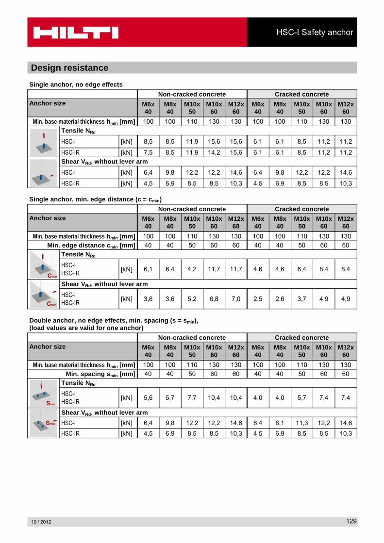
Design resistance
Single anchor, no edge effects
Non-cracked concrete Cracked concreteAnchor size M6x
40M8x40
M10x50
M10x60
M12x60
M6x40
M8x40
M10x50
M10x60
M12x60
���������������������������� hmin [mm] 100 100 110 130 130 100 100 110 130 130
Tensile NRd
HSC-I [kN] 8,5 8,5 11,9 15,6 15,6 6,1 6,1 8,5 11,2 11,2
HSC-IR [kN] 7,5 8,5 11,9 14,2 15,6 6,1 6,1 8,5 11,2 11,2
Shear VRd, without lever arm
HSC-I [kN] 6,4 9,8 12,2 12,2 14,6 6,4 9,8 12,2 12,2 14,6
HSC-IR [kN] 4,5 6,9 8,5 8,5 10,3 4,5 6,9 8,5 8,5 10,3
Single anchor, min. edge distance (c = cmin)
Non-cracked concrete Cracked concreteAnchor size M6x
40M8x40
M10x50
M10x60
M12x60
M6x40
M8x40
M10x50
M10x60
M12x60
���������������������������� hmin [mm] 100 100 110 130 130 100 100 110 130 130
Min. edge distance cmin [mm] 40 40 50 60 60 40 40 50 60 60
Tensile NRd
HSC-IHSC-IR
[kN] 6,1 6,4 4,2 11,7 11,7 4,6 4,6 6,4 8,4 8,4
Shear VRd, without lever arm
HSC-IHSC-IR
[kN] 3,6 3,6 5,2 6,8 7,0 2,5 2,6 3,7 4,9 4,9
Double anchor, no edge effects, min. spacing (s = smin), (load values are valid for one anchor)
Non-cracked concrete Cracked concreteAnchor size M6x
40M8x40
M10x50
M10x60
M12x60
M6x40
M8x40
M10x50
M10x60
M12x60
���������������������������� hmin [mm] 100 100 110 130 130 100 100 110 130 130
Min. spacing smin [mm] 40 40 50 60 60 40 40 50 60 60
Tensile NRd
HSC-IHSC-IR
[kN] 5,6 5,7 7,7 10,4 10,4 4,0 4,0 5,7 7,4 7,4
Shear VRd, without lever arm
HSC-I [kN] 6,4 9,8 12,2 12,2 14,6 6,4 8,1 11,3 12,2 14,6
HSC-IR [kN] 4,5 6,9 8,5 8,5 10,3 4,5 6,9 8,5 8,5 10,3