Hilti Fastening Technology Manual - HIT-HY 200 Injectable Mortar With HIT-V Anchor Rod
16
page 92 April 2013 Hilti HIT-HY 200 with HIT-V Hilti HIT-HY 200 with HIT-V Injection Mortar System Benefits ■ Suitable for non-cracked and cracked concrete C 20/25 to C 50/60 ■ Suitable for dry and water saturated concrete ■ High loading capacity, excellent handling and fast curing ■ Small edge distance and anchor spacing possible ■ Large diameter applications ■ Max In service temperature range up to 120°C short term/ 72°C long term ■ Manual cleaning for borehole diameter up to 20mm and hef ≤ 10d for non-cracked concrete only ■ Embedment depth range: from 60 ... 160 mm for M8 to 120 ... 600 mm for M30 Approvals / certificates Description Authority / Laboratory No. / date of issue European technical approval a) DIBt, Berlin ETA-12/0084 / 2012-08-08 (Hilti HIT-HY 200-R) Fire test report IBMB, Brunswick 3501/676/13 / 2012-08-03 a) All data given in this section according ETA-11/0493 and ETA-12/0084, issue 2012-08-08. Service temperature range Hilti HIT-HY 200 injection mortar may be applied in the temperature ranges given below. An elevated base material temperature may lead to a reduction of the design bond resistance. Temperature range Base material temperature Maximum long term base material temperature Maximum short term base material temperature Temperature range I -40 °C to +40 °C +24 °C +40 °C Temperature range II -40 °C to +80 °C +50 °C +80 °C Temperature range III -40 °C to +120 °C +72 °C +120 °C Max short term base material temperature Short-term elevated base material temperatures are those that occur over brief intervals, e.g. as a result of diurnal cycling. Max long term base material temperature Long-term elevated base material temperatures are roughly constant over significant periods of time Hilti HIT-HY 200-R 500 ml foil pack (also available as 330 ml foil pack) Static mixer HIT-V rods HIT-V (Zinc) HIT-V-F (Gal) HIT-V-R (A4-70) HIT-V-HCR rods CE conformity Small edge distance & spacing European Technical Approval Concrete A4 316 Corrosion resistance HCR highMo High corrosion resistance Variable embedment depth Tensile zone PROFIS anchor design software
-
Upload
sandeepsharmafj -
Category
Documents
-
view
255 -
download
0
description
Hilti anchor design
Transcript of Hilti Fastening Technology Manual - HIT-HY 200 Injectable Mortar With HIT-V Anchor Rod
page 92 April 2013
Hilti HIT-HY 200 with HIT-V
Hilti HIT-HY 200 with HIT-V
Injection Mortar System Benefits
■ Suitable for non-cracked and cracked concrete C 20/25 to C 50/60
■ Suitable for dry and water saturated concrete
■ High loading capacity, excellent handling and fast curing
■ Small edge distance and anchor spacing possible
■ Large diameter applications■ Max In service temperature range
up to 120°C short term/ 72°C long term
■ Manual cleaning for borehole diameter up to 20mm and hef ≤ 10d for non-cracked concrete only
■ Embedment depth range: from 60 ... 160 mm for M8 to 120 ... 600 mm for M30
Approvals / certificatesDescription Authority / Laboratory No. / date of issue
European technical approval a) DIBt, Berlin ETA-12/0084 / 2012-08-08 (Hilti HIT-HY 200-R)
Fire test report IBMB, Brunswick 3501/676/13 / 2012-08-03
a) All data given in this section according ETA-11/0493 and ETA-12/0084, issue 2012-08-08.
Service temperature rangeHilti HIT-HY 200 injection mortar may be applied in the temperature ranges given below. An elevated base material temperature may lead to a reduction of the design bond resistance.
Temperature range Base material temperature Maximum long term base material temperature
Maximum short term base material temperature
Temperature range I -40 °C to +40 °C +24 °C +40 °CTemperature range II -40 °C to +80 °C +50 °C +80 °CTemperature range III -40 °C to +120 °C +72 °C +120 °C
Max short term base material temperatureShort-term elevated base material temperatures are those that occur over brief intervals, e.g. as a result of diurnal cycling.
Max long term base material temperatureLong-term elevated base material temperatures are roughly constant over significant periods of time
Hilti HIT-HY 200-R500 ml foil pack(also available as 330 ml foil pack)
Static mixer
HIT-V rodsHIT-V (Zinc)HIT-V-F (Gal)HIT-V-R (A4-70)HIT-V-HCR rods
CE conformity
Small edge distance
& spacing
European Technical Approval
Concrete
A4 316
Corrosion resistance
HCR highMo
High corrosion resistance
Variable embedment
depth
Tensile zone
PROFIS anchor design
software
April 2013 page 93
Hilti HIT-HY 200 with HIT-V
Design process for typical anchor layoutsThe design values in the tables are obtained from Profis V2.2.1 in compliance with the design method according to EOTA TR 029. Design resistance according to data given in ETA-12/0084, issue 2012-08-08.■ Influence of concrete strength ■ Influence of edge distance ■ Influence of spacing
The design method is based on the following simplification:■ No different loads are acting on individual anchors (no eccentricity)
The values are valid for the anchor configuration.
For more complex fastening applications please use the anchor design software PROFIS Anchor.
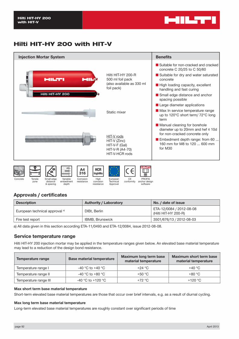
STEP 1: TENSION LOADING
The design tensile resistance NRd is the lower of:
■ Combined pull-out and concrete cone resistance NRd,p = fB,p • N*Rd,p
N*Rd,p is obtained from the relevant design tables
fB,p influence of concrete strength on combined pull-out and concrete cone resistance
Concrete Strengths f’c,cyl (MPa) 20 25 32 40 50fB,p 1.00 1.00 1.00 1.00 1.00
■ Concrete cone or concrete splitting resistance NRd,c = fB • N*Rd,c
N*Rd,c is obtained from the relevant design tables
fB influence of concrete strength on concrete cone resistance
Concrete Strengths f’c,cyl (MPa) 20 25 32 40 50fB 0.79 0.87 1.00 1.11 1.22
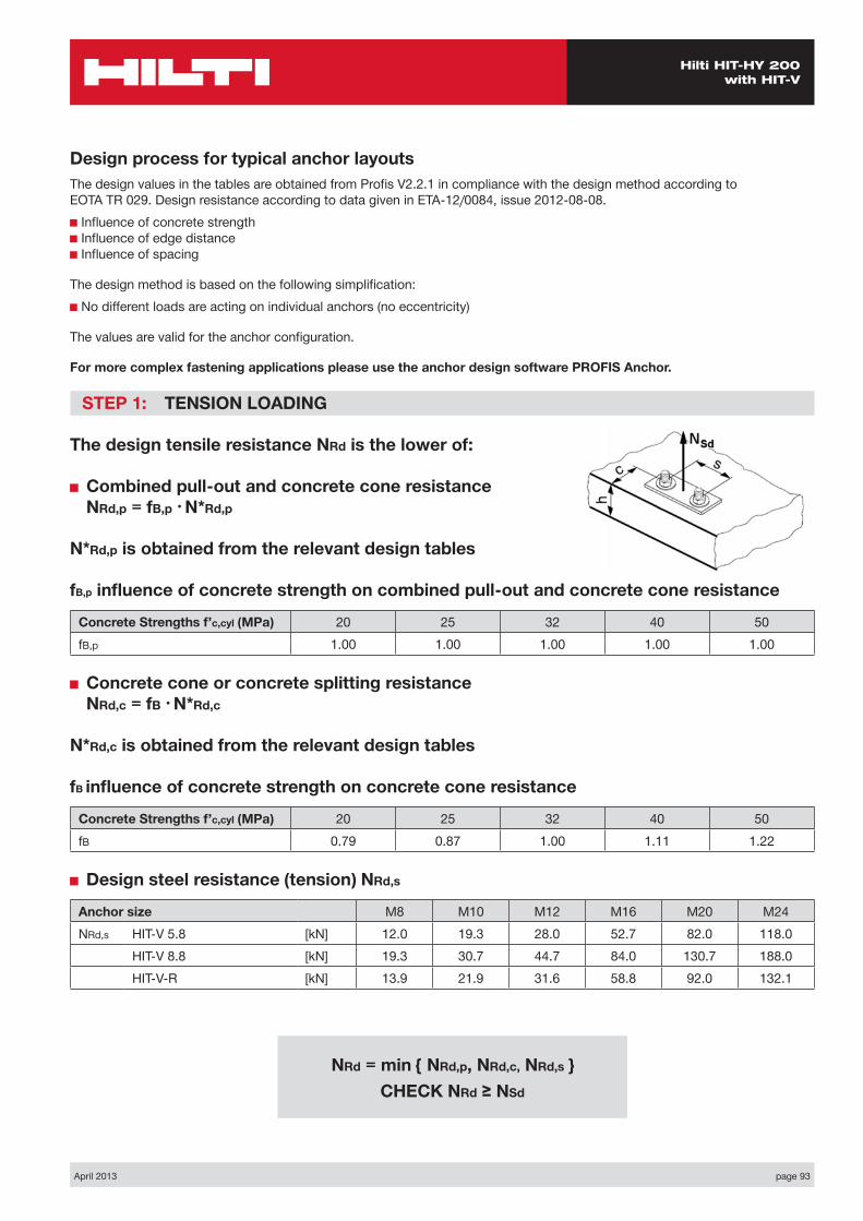
■ Design steel resistance (tension) NRd,s
Anchor size M8 M10 M12 M16 M20 M24NRd,s HIT-V 5.8 [kN] 12.0 19.3 28.0 52.7 82.0 118.0
HIT-V 8.8 [kN] 19.3 30.7 44.7 84.0 130.7 188.0HIT-V-R [kN] 13.9 21.9 31.6 58.8 92.0 132.1
NRd = min { NRd,p, NRd,c, NRd,s } CHECK NRd ≥ NSd
page 94 April 2013
Hilti HIT-HY 200 with HIT-V
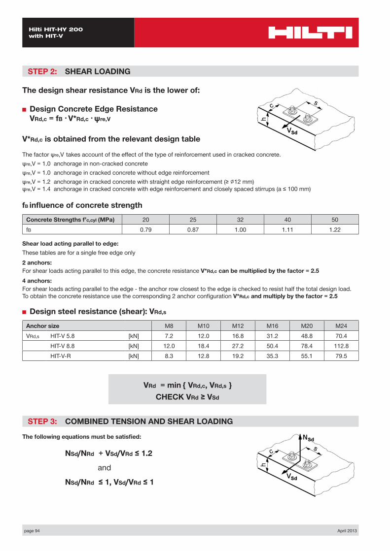
STEP 2: SHEAR LOADING
The design shear resistance VRd is the lower of:
■ Design Concrete Edge Resistance VRd,c = fB • V*Rd,c • ψre,V
V*Rd,c is obtained from the relevant design table
The factor ψre,V takes account of the effect of the type of reinforcement used in cracked concrete.ψre,V = 1.0 anchorage in non-cracked concreteψre,V = 1.0 anchorage in cracked concrete without edge reinforcementψre,V = 1.2 anchorage in cracked concrete with straight edge reinforcement (≥ ∅12 mm) ψre,V = 1.4 anchorage in cracked concrete with edge reinforcement and closely spaced stirrups (a ≤ 100 mm)
fB influence of concrete strength
Concrete Strengths f’c,cyl (MPa) 20 25 32 40 50fB 0.79 0.87 1.00 1.11 1.22
Shear load acting parallel to edge:These tables are for a single free edge only2 anchors:For shear loads acting parallel to this edge, the concrete resistance V*Rd,c can be multiplied by the factor = 2.54 anchors:For shear loads acting parallel to the edge - the anchor row closest to the edge is checked to resist half the total design load. To obtain the concrete resistance use the corresponding 2 anchor configuration V*Rd,c and multiply by the factor = 2.5
■ Design steel resistance (shear): VRd,s
Anchor size M8 M10 M12 M16 M20 M24VRd,s HIT-V 5.8 [kN] 7.2 12.0 16.8 31.2 48.8 70.4
HIT-V 8.8 [kN] 12.0 18.4 27.2 50.4 78.4 112.8HIT-V-R [kN] 8.3 12.8 19.2 35.3 55.1 79.5
STEP 3: COMBINED TENSION AND SHEAR LOADING
The following equations must be satisfied:
NSd/NRd + VSd/VRd ≤ 1.2
and
NSd/NRd ≤ 1, VSd/VRd ≤ 1
VRd = min { VRd,c, VRd,s } CHECK VRd ≥ VSd
April 2013 page 95
Hilti HIT-HY 200 with HIT-V
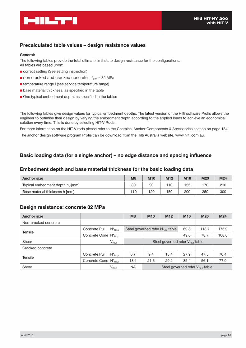
Basic loading data (for a single anchor) – no edge distance and spacing influence
Embedment depth and base material thickness for the basic loading data
Anchor size M8 M10 M12 M16 M20 M24
Typical embedment depth hef [mm] 80 90 110 125 170 210
Base material thickness h [mm] 110 120 150 200 250 300
Precalculated table values – design resistance values
General:The following tables provide the total ultimate limit state design resistance for the configurations. All tables are based upon:■ correct setting (See setting instruction)■ non cracked and cracked concrete – fc,cyl = 32 MPa■ temperature range I (see service temperature range)■ base material thickness, as specified in the table■ One typical embedment depth, as specified in the tables
The following tables give design values for typical embedment depths. The latest version of the Hilti software Profis allows the engineer to optimise their design by varying the embedment depth according to the applied loads to achieve an economical solution every time. This is done by selecting HIT-V-Rods.For more information on the HIT-V rods please refer to the Chemical Anchor Components & Accessories section on page 134.The anchor design software program Profis can be download from the Hilti Australia website, www.hilti.com.au.
Design resistance: concrete 32 MPa
Anchor size M8 M10 M12 M16 M20 M24Non-cracked concrete
Tensile Concrete Pull N*Rd,p Steel governed refer NRd,s table 69.8 118.7 175.9Concrete Cone N*Rd,c 49.6 78.7 108.0
Shear VRd,s Steel governed refer VRd,s tableCracked concrete
Tensile Concrete Pull N*Rd,p 6.7 9.4 18.4 27.9 47.5 70.4Concrete Cone N*Rd,c 18.1 21.6 29.2 35.4 56.1 77.0
Shear VRd,s NA Steel governed refer VRd,s table

page 96 April 2013
Hilti HIT-HY 200 with HIT-V
Nsd
Vsd
S1
C
h
Two anchors Table 1: One edge influence
Design Data: fc,cyl=32 MPa
Anchor size M8 M10 M12 M16 M20 M24Typical embedment depth hef [mm] 80 90 110 125 170 210
Base material thickness h [mm] 110 120 150 200 250 300
ANCHOR
M8Edge C (mm)
40 80 100 150 170spacings1 (mm)
tension shear tension shear tension shear tension shear tension shearN*Rd,p N*Rd,c V*Rrd,c N*Rd,p N*Rd,c V*Rrd,c N*Rd,p N*Rd,c V*Rrd,c N*Rd,p N*Rd,c V*Rrd,c N*Rd,p N*Rd,c V*Rrd,c
40 14.5 13.5 6.3 20.4 17.6 13.2 13.6 19.8 15.4 27.1 25.8 21.0 27.1 28.4 23.2
80 16.4 14.9 7.9 23.0 19.4 15.0 26.7 21.8 17.2 30.7 28.5 22.7 30.7 31.4 24.9
100 17.3 15.6 8.6 24.3 20.3 15.9 28.2 22.9 18.1 32.4 29.8 23.6 32.4 32.9 25.7
120 18.2 16.4 9.4 25.6 21.2 16.9 29.8 23.9 19.0 34.2 31.2 24.4 34.2 34.4 26.6
150 19.7 17.4 9.4 27.6 22.6 18.3 32.1 25.5 20.4 36.8 33.2 25.7 36.8 36.6 27.9
200 22.0 19.2 9.4 30.9 24.9 20.6 35.9 28.1 22.6 41.2 36.6 27.9 41.2 43.0 30.0
ANCHOR
M10Edge C (mm)
50 80 100 150 200spacings1 (mm)
tension shear tension shear tension shear tension shear tension shearN*Rd,p N*Rd,c V*Rrd,c N*Rd,p N*Rd,c V*Rrd,c N*Rd,p N*Rd,c V*Rrd,c N*Rd,p N*Rd,c V*Rrd,c N*Rd,p N*Rd,c V*Rrd,c
50 20.7 16.6 9.0 26.0 19.7 15.0 29.9 21.9 17.4 37.2 27.8 23.4 37.2 34.1 29.3
100 23.9 18.4 11.3 30.1 21.9 17.6 34.6 24.3 19.9 43.1 30.9 25.7 43.1 38.0 31.5
150 27.2 20.3 13.5 34.2 24.1 20.2 39.2 26.8 22.4 48.9 34.1 28.1 48.9 41.8 33.8
200 30.4 22.2 13.5 38.2 23.3 22.8 43.9 29.2 24.9 54.7 37.2 30.4 54.7 45.6 36.0
250 33.6 24.0 13.5 42.3 28.5 24.8 48.6 31.7 27.4 60.5 40.3 32.7 60.5 49.4 38.3
300 34.9 25.9 13.5 43.9 30.7 24.8 50.4 34.1 29.9 62.8 43.4 35.1 62.8 53.3 40.6
ANCHOR
M12Edge C (mm)
60 80 100 150 200spacings1 (mm)
tension shear tension shear tension shear tension shear tension shearN*Rd,p N*Rd,c V*Rrd,c N*Rd,p N*Rd,c V*Rrd,c N*Rd,p N*Rd,c V*Rrd,c N*Rd,p N*Rd,c V*Rrd,c N*Rd,p N*Rd,c V*Rrd,c
60 30.0 23.5 12.3 34.2 25.9 16.7 38.6 28.5 21.4 50.6 35.2 28.2 54.5 42.6 35.0
100 33.1 25.3 14.4 37.7 27.9 18.9 42.5 30.6 23.8 55.7 37.8 30.5 60.0 45.8 37.1
150 37.0 27.5 16.9 42.1 30.3 21.7 47.5 33.3 26.7 62.2 41.1 33.2 67.0 49.8 39.7
200 40.8 29.7 18.5 46.5 32.8 24.5 52.4 35.9 29.7 68.7 44.5 36.0 74.0 53.8 42.4
250 44.7 31.9 18.5 50.8 35.2 26.7 57.3 38.6 32.7 75.2 47.8 38.7 81.0 57.8 45.0
300 48.5 34.1 18.5 55.2 37.6 26.7 62.3 41.3 35.7 81.7 51.1 41.5 88.0 61.8 47.7

April 2013 page 97
Hilti HIT-HY 200 with HIT-V
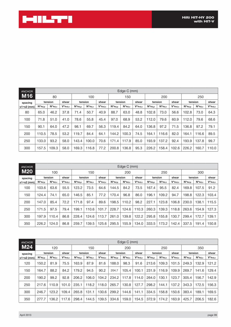
ANCHOR
M24Edge C (mm)
120 150 200 250 350spacings1 (mm)
tension shear tension shear tension shear tension shear tension shearN*Rd,p N*Rd,c V*Rrd,c N*Rd,p N*Rd,c V*Rrd,c N*Rd,p N*Rd,c V*Rrd,c N*Rd,p N*Rd,c V*Rrd,c N*Rd,p N*Rd,c V*Rrd,c
120 117.8 67.1 39.7 130.3 72.7 49.7 152.5 82.5 67.5 176.2 92.8 77.6 209.4 115.1 97.6
150 122.5 69.2 42.3 135.5 75.0 52.3 158.6 85.0 70.3 183.3 95.7 80.2 217.8 118.6 100.1
200 130.3 73.6 46.4 144.2 78.7 56.6 168.7 89.3 75.0 195.0 100.4 84.7 231.8 124.6 104.2
250 138.2 76.1 50.5 152.9 82.4 61.0 178.9 93.5 79.7 206.7 105.2 89.2 245.7 130.5 108.4
300 146.0 79.5 54.7 161.6 86.2 65.3 189.0 97.7 84.3 218.5 110.0 93.6 259.7 136.4 112.6
350 153.9 83.0 58.8 170.3 89.9 69.7 199.2 102.0 89.0 230.2 114.7 98.1 273.7 142.3 116.8
ANCHOR
M16Edge C (mm)
80 100 150 200 250spacings1 (mm)
tension shear tension shear tension shear tension shear tension shearN*Rd,p N*Rd,c V*Rrd,c N*Rd,p N*Rd,c V*Rrd,c N*Rd,p N*Rd,c V*Rrd,c N*Rd,p N*Rd,c V*Rrd,c N*Rd,p N*Rd,c V*Rrd,c
80 50.0 35.5 19.3 55.9 39.7 24.4 71.7 50.9 36.2 84.7 60.2 44.1 84.7 60.2 52.0
100 52.2 37.1 20.5 58.3 41.4 25.7 74.8 53.1 37.5 88.4 62.8 45.4 88.4 62.8 53.2
150 57.7 41.0 23.6 64.4 45.8 28.9 82.7 58.7 41.0 97.7 69.4 48.6 97.7 69.4 56.3
200 63.2 44.9 26.6 70.6 50.1 32.1 90.6 64.3 44.4 107.0 76.0 51.9 107.0 76.0 59.4
250 68.7 48.8 29.1 76.7 54.5 35.3 98.4 69.9 47.8 116.4 82.7 55.1 116.4 82.7 62.6
300 74.2 54.2 29.1 82.9 58.9 38.6 106.3 75.1 51.2 125.7 89.3 58.4 125.7 89.3 65.7
ANCHOR
M20Edge C (mm)
120 150 200 250 300spacings1 (mm)
tension shear tension shear tension shear tension shear tension shearN*Rd,p N*Rd,c V*Rrd,c N*Rd,p N*Rd,c V*Rrd,c N*Rd,p N*Rd,c V*Rrd,c N*Rd,p N*Rd,c V*Rrd,c N*Rd,p N*Rd,c V*Rrd,c
100 80.8 51.6 28.9 98.8 60.9 44.0 118.5 70.9 55.5 139.7 81.5 64.6 142.0 92.8 73.5
150 87.4 55.0 32.5 106.9 64.9 48.0 128.2 75.5 59.5 151.2 86.8 68.4 153.6 98.9 77.2
200 94.0 58.4 36.1 115.0 68.9 52.0 137.9 80.1 63.5 162.6 92.1 72.2 165.2 104.9 80.9
250 100.7 61.8 39.7 123.1 72.8 56.0 147.6 84.7 67.4 174.1 97.5 76.0 176.9 111.0 84.6
300 107.3 65.1 43.4 131.2 76.8 60.0 157.3 89.4 71.4 185.6 102.8 79.8 188.5 117.1 88.2
350 113.9 68.5 43.4 139.3 80.8 64.1 167.0 94.0 75.4 197.0 108.1 83.6 200.1 123.2 92.0
page 98 April 2013
Hilti HIT-HY 200 with HIT-V
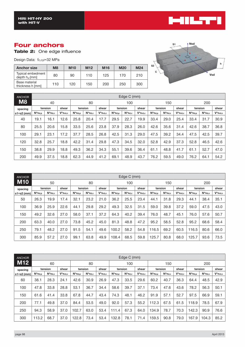
Four anchors Table 2: One edge influence
Design Data: fc,cyl=32 MPa
Anchor size M8 M10 M12 M16 M20 M24Typical embedment depth hef [mm] 80 90 110 125 170 210
Base material thickness h [mm] 110 120 150 200 250 300
ANCHOR
M8Edge C (mm)
40 80 100 150 200spacing
s1=s2 (mm)
tension shear tension shear tension shear tension shear tension shearN*Rd,p N*Rd,c V*Rrd,c N*Rd,p N*Rd,c V*Rrd,c N*Rd,p N*Rd,c V*Rrd,c N*Rd,p N*Rd,c V*Rrd,c N*Rd,p N*Rd,c V*Rrd,c
40 19.1 16.1 12.6 25.8 20.4 17.7 29.5 22.7 19.9 33.4 29.0 25.4 33.4 31.7 30.9
80 25.5 20.6 15.8 33.5 25.6 23.8 37.9 28.3 26.0 42.6 35.6 31.4 42.6 38.7 36.8
100 29.1 23.1 17.2 37.7 28.5 26.8 42.5 31.3 29.0 47.5 39.2 34.4 47.5 42.5 39.7
120 32.8 25.7 18.8 42.2 31.4 29.8 47.3 34.5 32.0 52.8 42.9 37.3 52.8 46.5 42.6
150 38.8 29.9 18.8 49.3 36.2 34.3 55.1 39.6 36.4 61.1 48.8 41.7 61.1 52.7 47.0
200 49.9 37.5 18.8 62.3 44.9 41.2 69.1 48.9 43.7 76.2 59.5 49.0 76.2 64.1 54.2
ANCHOR
M10Edge C (mm)
50 80 100 150 200spacing
s1=s2 (mm)
tension shear tension shear tension shear tension shear tension shearN*Rd,p N*Rd,c V*Rrd,c N*Rd,p N*Rd,c V*Rrd,c N*Rd,p N*Rd,c V*Rrd,c N*Rd,p N*Rd,c V*Rrd,c N*Rd,p N*Rd,c V*Rrd,c
50 26.3 19.9 17.4 32.1 23.2 21.0 36.2 25.5 23.4 44.1 31.8 29.3 44.1 38.4 35.1
100 36.9 25.9 22.6 44.1 29.8 29.2 49.3 32.5 31.5 59.0 39.8 37.2 59.0 47.5 43.0
150 49.2 32.6 27.0 58.0 37.1 37.2 64.3 40.2 39.4 76.0 48.7 45.1 76.0 57.6 50.7
200 63.3 40.0 27.0 73.8 45.2 45.0 81.3 48.8 47.2 95.2 58.5 52.8 95.2 68.6 58.4
250 79.1 48.2 27.0 91.5 54.1 49.6 100.2 58.2 54.8 116.5 69.2 60.5 116.5 80.6 66.0
300 85.9 57.2 27.0 99.1 63.8 49.9 108.4 68.5 59.8 125.7 80.8 68.0 125.7 93.6 73.5
ANCHOR
M12Edge C (mm)
60 80 100 150 200spacing
s1=s2 (mm)
tension shear tension shear tension shear tension shear tension shearN*Rd,p N*Rd,c V*Rrd,c N*Rd,p N*Rd,c V*Rrd,c N*Rd,p N*Rd,c V*Rrd,c N*Rd,p N*Rd,c V*Rrd,c N*Rd,p N*Rd,c V*Rrd,c
60 38.1 28.3 24.1 42.6 30.9 26.9 47.3 33.5 29.6 60.2 40.7 36.3 64.4 48.5 42.9
100 47.8 33.8 28.8 53.1 36.7 34.4 58.6 39.7 37.1 73.4 47.6 43.6 78.2 56.3 50.1
150 61.6 41.4 33.8 67.8 44.7 43.4 74.3 48.1 46.2 91.9 57.1 52.7 97.5 66.9 59.1
200 77.1 49.8 37.0 84.4 53.5 49.0 92.0 57.3 55.2 112.3 67.5 61.5 118.9 78.5 67.9
250 94.3 58.9 37.0 102.7 63.0 53.4 111.4 67.3 64.0 134.9 78.7 70.3 142.3 90.9 76.6
300 113.2 68.7 37.0 122.8 73.4 53.4 132.8 78.1 71.4 159.5 90.8 79.0 167.9 104.3 85.2
Nsd
Vsd
S2
S1
C
h
April 2013 page 99
Hilti HIT-HY 200 with HIT-V
ANCHOR
M24Edge C (mm)
120 150 200 250 350spacing
s1=s2 (mm)
tension shear tension shear tension shear tension shear tension shearN*Rd,p N*Rd,c V*Rrd,c N*Rd,p N*Rd,c V*Rrd,c N*Rd,p N*Rd,c V*Rrd,c N*Rd,p N*Rd,c V*Rrd,c N*Rd,p N*Rd,c V*Rrd,c
120 150.2 81.9 75.5 163.9 87.9 81.6 188.0 98.3 91.6 213.6 109.3 101.5 249.3 132.9 121.2
150 164.7 88.2 84.2 179.2 94.5 90.2 204.7 105.4 100.1 231.9 116.9 109.9 269.7 141.6 129.4
200 190.2 99.2 92.8 206.2 106.0 104.2 234.2 117.8 114.0 264.0 130.1 123.7 305.4 156.7 142.9
250 217.6 110.9 101.0 235.1 118.2 118.0 265.7 130.8 127.7 298.2 144.1 137.2 343.3 172.5 156.3
300 246.7 123.2 109.4 265.8 131.1 130.6 299.2 144.6 141.1 334.5 158.8 150.6 383.4 189.1 169.5
350 277.7 136.2 117.6 298.4 144.5 139.5 334.6 159.0 154.5 372.9 174.2 163.9 425.7 206.5 182.6
ANCHOR
M16Edge C (mm)
80 100 150 200 250spacing
s1=s2 (mm)
tension shear tension shear tension shear tension shear tension shearN*Rd,p N*Rd,c V*Rrd,c N*Rd,p N*Rd,c V*Rrd,c N*Rd,p N*Rd,c V*Rrd,c N*Rd,p N*Rd,c V*Rrd,c N*Rd,p N*Rd,c V*Rrd,c
80 65.0 46.2 37.8 71.4 50.7 40.9 88.7 63.0 48.8 102.8 73.0 56.6 102.8 73.0 64.3
100 71.8 51.0 41.0 78.6 55.8 45.4 97.0 68.9 53.2 112.0 79.6 60.9 112.0 79.6 68.6
150 90.1 64.0 47.2 98.1 69.7 56.3 119.4 84.2 64.0 136.8 97.2 71.5 136.8 97.2 79.1
200 110.5 78.5 53.2 119.7 84.4 64.1 144.2 100.3 74.5 164.1 116.6 82.0 164.1 116.6 89.5
250 133.0 93.2 58.0 143.4 100.0 70.6 171.4 117.9 85.0 193.9 137.2 92.4 193.9 137.8 99.7
300 157.5 109.3 58.0 169.3 116.8 77.2 200.8 136.8 95.3 226.2 158.4 102.6 226.2 160.7 110.0
ANCHOR
M20Edge C (mm)
100 150 200 250 300spacing
s1=s2 (mm)
tension shear tension shear tension shear tension shear tension shearN*Rd,p N*Rd,c V*Rrd,c N*Rd,p N*Rd,c V*Rrd,c N*Rd,p N*Rd,c V*Rrd,c N*Rd,p N*Rd,c V*Rrd,c N*Rd,p N*Rd,c V*Rrd,c
100 103.6 63.6 55.5 123.2 73.5 64.6 144.5 84.2 73.5 167.4 95.5 82.4 169.8 107.5 91.2
150 124.4 74.1 65.0 146.5 85.1 77.2 170.4 96.8 86.0 196.1 109.2 94.7 198.8 122.3 103.4
200 147.0 85.4 72.2 171.8 97.4 89.6 198.5 110.2 98.2 227.1 123.8 106.8 230.0 138.1 115.5
250 171.5 97.5 79.4 199.1 110.6 101.7 228.7 124.6 110.3 260.3 139.3 118.8 263.6 154.9 127.3
300 197.9 110.4 86.8 228.4 124.6 113.7 261.0 139.8 122.2 295.8 155.8 130.7 299.4 172.7 139.1
350 226.2 124.0 86.8 259.7 139.5 125.6 295.5 155.9 134.0 333.5 173.2 142.4 337.5 191.4 150.8

page 100 April 2013
Hilti HIT-HY 200 with HIT-V
Nsd
Vsd
S1
C
h
Two anchors Table 1: One edge influence – cracked concrete
Design Data: fc,cyl=32 MPa – Cracked Concrete
Anchor size M10 M12 M16 M20 M24Typical embedment depth hef [mm] 90 110 125 170 210
Base material thickness h [mm] 120 150 200 250 300
ANCHOR
M10Edge C (mm)
50 80 100 150 200spacings1 (mm)
tension shear tension shear tension shear tension shear tension shearN*Rd,p N*Rd,c V*Rrd,c N*Rd,p N*Rd,c V*Rrd,c N*Rd,p N*Rd,c V*Rrd,c N*Rd,p N*Rd,c V*Rrd,c N*Rd,p N*Rd,c V*Rrd,c
50 7.3 11.8 6.4 9.1 14.0 10.6 10.5 15.6 12.4 13.1 19.8 16.6 13.1 24.3 20.8
100 8.0 13.1 8.0 10.1 15.6 12.5 11,6 17.3 14.1 14.4 22,0 18.5 14.4 27.1 22.4
150 8.8 14.5 9.6 11.0 17.2 14.3 12.7 19.1 15.9 15.8 24.3 19.9 15.8 29.8 24.0
200 9.5 15.8 9.6 11.9 18.7 16.2 13.7 20.8 17.7 17.1 26.5 21.6 17.1 32.5 25.5
250 10.2 17.1 9.6 12.8 20.3 17.6 14.7 22.6 19.4 18.4 28.7 23.2 18.4 35.2 27.1
300 10.5 18.4 9.6 13.2 21.9 17.6 15.1 24.3 21.2 18.9 30.9 24.9 18.9 39.0 28.7
ANCHOR
M12Edge C (mm)
60 80 100 150 200spacings1 (mm)
tension shear tension shear tension shear tension shear tension shearN*Rd,p N*Rd,c V*Rrd,c N*Rd,p N*Rd,c V*Rrd,c N*Rd,p N*Rd,c V*Rrd,c N*Rd,p N*Rd,c V*Rrd,c N*Rd,p N*Rd,c V*Rrd,c
60 13.4 16.8 8.7 15.3 18.5 11.8 17.3 20.3 15.2 22.6 25.1 20.0 24.4 30.4 24.8
100 14.5 18.0 10.2 16.5 19.9 13.4 18.6 21.8 16.9 24.4 27.0 21.6 26.3 32.6 26.3
150 15.8 19.6 12.0 18.0 21.6 15.4 20.3 23.7 19.0 26.6 29.3 23.6 28.6 35.5 28.2
200 17.1 21.2 13.1 19.4 23.4 17.4 21.9 25.6 21.1 28.7 31.7 25.5 31.0 38.4 30.0
250 18.4 22.8 13.1 20.9 25.1 18.9 23.6 27.5 23.2 30.9 34.1 27.5 33.2 41.2 31.9
300 19.6 24.3 13.1 22.3 26.8 18.9 25.2 29.4 25.3 33.0 36.4 29.4 35.5 44.1 33.8
ANCHOR
M16Edge C (mm)
80 100 150 200 250spacings1 (mm)
tension shear tension shear tension shear tension shear tension shearN*Rd,p N*Rd,c V*Rrd,c N*Rd,p N*Rd,c V*Rrd,c N*Rd,p N*Rd,c V*Rrd,c N*Rd,p N*Rd,c V*Rrd,c N*Rd,p N*Rd,c V*Rrd,c
80 21.4 25.3 13.7 23.8 28.3 17.3 30.6 36.3 25.6 36.2 42.9 31.3 36.2 42.9 36.8
100 22.2 26.5 14.6 24.7 29.5 18.2 31.7 37.9 26.6 37.5 44.8 32.2 37.5 44.8 37.7
150 24.2 29.2 16.7 27.0 32.6 20.5 34.6 41.9 29.0 40.9 49.5 34.5 40.9 49.5 39.9
200 26.1 32.0 18.9 29.2 35.7 22.8 37.4 45.9 31.4 44.3 54.2 36.8 44.3 54.2 42.1
250 28.1 34.8 20.6 31.4 38.9 25.0 40.3 49.9 33.9 47.6 58.9 39.1 47.6 58.9 44.3
300 30.1 37.6 20.6 33.6 42.0 27.3 43.1 53.5 36.3 50.9 63.6 41.4 50.9 63.6 46.6
Tensile zone
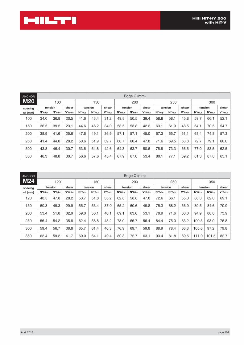
April 2013 page 101
Hilti HIT-HY 200 with HIT-V
ANCHOR
M24Edge C (mm)
120 150 200 250 350spacings1 (mm)
tension shear tension shear tension shear tension shear tension shearN*Rd,p N*Rd,c V*Rrd,c N*Rd,p N*Rd,c V*Rrd,c N*Rd,p N*Rd,c V*Rrd,c N*Rd,p N*Rd,c V*Rrd,c N*Rd,p N*Rd,c V*Rrd,c
120 48.5 47.8 28.2 53.7 51.8 35.2 62.8 58.8 47.8 72.6 66.1 55.0 86.3 82.0 69.1
150 50.3 49.3 29.9 55.7 53.4 37.0 65.2 60.6 49.8 75.3 68.2 56.9 89.5 84.6 70.9
200 53.4 51.8 32.9 59.0 56.1 40.1 69.1 63.6 53.1 78.9 71.6 60.0 94.9 88.8 73.9
250 56.4 54.2 35.8 62.4 58.8 43.2 73.0 66.7 56.4 84.4 75.0 63.2 100.3 93.0 76.8
300 59.4 56.7 38.8 65.7 61.4 46.3 76.9 69.7 59.8 88.9 78.4 66.3 105.6 97.2 79.8
350 62.4 59.2 41.7 69.0 64.1 49.4 80.8 72.7 63.1 93.4 81.8 69.5 111.0 101.5 82.7
ANCHOR
M20Edge C (mm)
100 150 200 250 300spacings1 (mm)
tension shear tension shear tension shear tension shear tension shearN*Rd,p N*Rd,c V*Rrd,c N*Rd,p N*Rd,c V*Rrd,c N*Rd,p N*Rd,c V*Rrd,c N*Rd,p N*Rd,c V*Rrd,c N*Rd,p N*Rd,c V*Rrd,c
100 34.0 36.8 20.5 41.6 43.4 31.2 49.8 50.5 39.4 58.8 58.1 45.8 59.7 66.1 52.1
150 36.5 39.2 23.1 44.6 46.2 34.0 53.5 53.8 42.2 63.1 61.9 48.5 64.1 70.5 54.7
200 38.9 41.6 25.6 47.6 49.1 36.9 57.1 57.1 45.0 67.3 65.7 51.1 68.4 74.8 57.3
250 41.4 44.0 28.2 50.6 51.9 39.7 60.7 60.4 47.8 71.6 69.5 53.8 72.7 79.1 60.0
300 43.8 46.4 30.7 53.6 54.8 42.6 64.3 63.7 50.6 75.8 73.3 56.5 77.0 83.5 62.5
350 46.3 48.8 30.7 56.6 57.6 45.4 67.9 67.0 53.4 80.1 77.1 59.2 81.3 87.8 65.1
page 102 April 2013
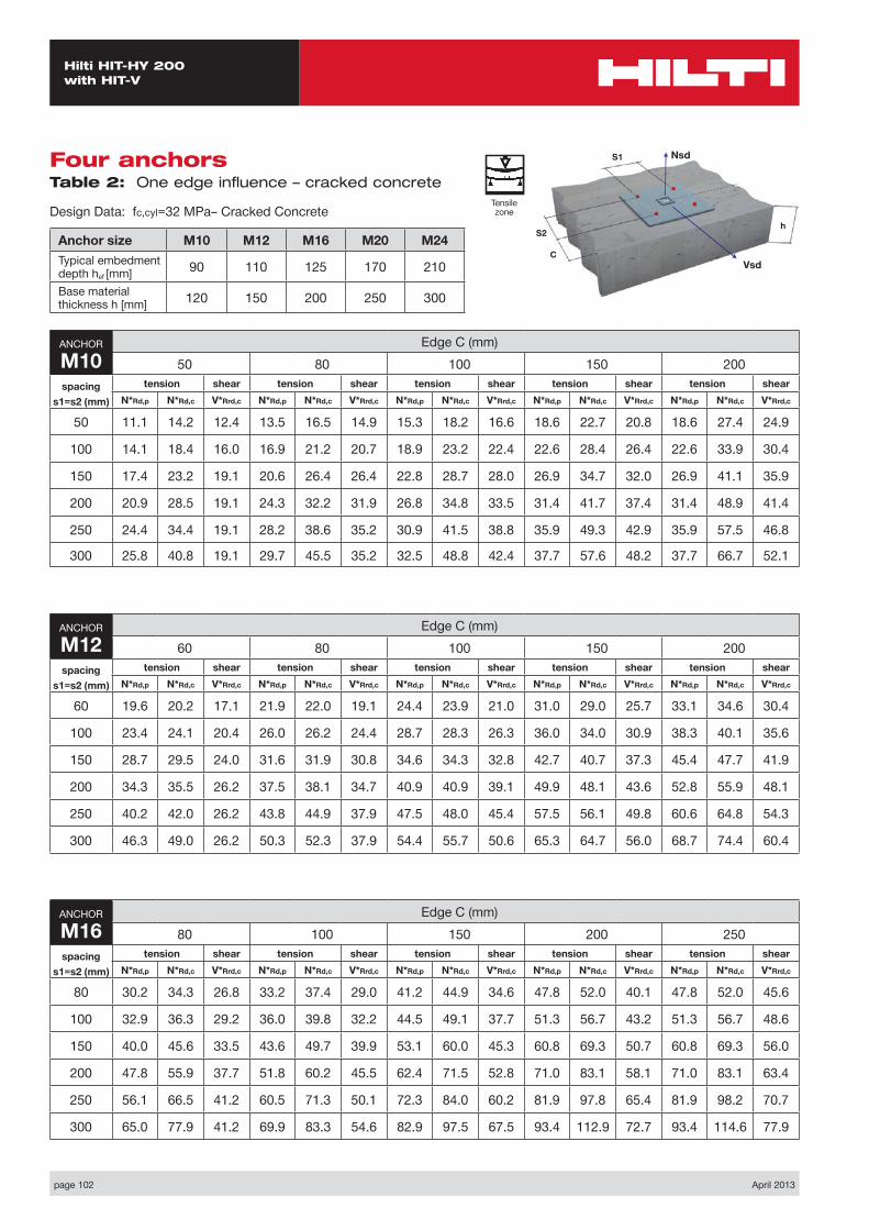
Hilti HIT-HY 200 with HIT-V
Four anchors Table 2: One edge influence – cracked concrete
Design Data: fc,cyl=32 MPa– Cracked Concrete
Anchor size M10 M12 M16 M20 M24Typical embedment depth hef [mm] 90 110 125 170 210
Base material thickness h [mm] 120 150 200 250 300
ANCHOR
M10Edge C (mm)
50 80 100 150 200spacing
s1=s2 (mm)
tension shear tension shear tension shear tension shear tension shearN*Rd,p N*Rd,c V*Rrd,c N*Rd,p N*Rd,c V*Rrd,c N*Rd,p N*Rd,c V*Rrd,c N*Rd,p N*Rd,c V*Rrd,c N*Rd,p N*Rd,c V*Rrd,c
50 11.1 14.2 12.4 13.5 16.5 14.9 15.3 18.2 16.6 18.6 22.7 20.8 18.6 27.4 24.9
100 14.1 18.4 16.0 16.9 21.2 20.7 18.9 23.2 22.4 22.6 28.4 26.4 22.6 33.9 30.4
150 17.4 23.2 19.1 20.6 26.4 26.4 22.8 28.7 28.0 26.9 34.7 32.0 26.9 41.1 35.9
200 20.9 28.5 19.1 24.3 32.2 31.9 26.8 34.8 33.5 31.4 41.7 37.4 31.4 48.9 41.4
250 24.4 34.4 19.1 28.2 38.6 35.2 30.9 41.5 38.8 35.9 49.3 42.9 35.9 57.5 46.8
300 25.8 40.8 19.1 29.7 45.5 35.2 32.5 48.8 42.4 37.7 57.6 48.2 37.7 66.7 52.1
ANCHOR
M12Edge C (mm)
60 80 100 150 200spacing
s1=s2 (mm)
tension shear tension shear tension shear tension shear tension shearN*Rd,p N*Rd,c V*Rrd,c N*Rd,p N*Rd,c V*Rrd,c N*Rd,p N*Rd,c V*Rrd,c N*Rd,p N*Rd,c V*Rrd,c N*Rd,p N*Rd,c V*Rrd,c
60 19.6 20.2 17.1 21.9 22.0 19.1 24.4 23.9 21.0 31.0 29.0 25.7 33.1 34.6 30.4
100 23.4 24.1 20.4 26.0 26.2 24.4 28.7 28.3 26.3 36.0 34.0 30.9 38.3 40.1 35.6
150 28.7 29.5 24.0 31.6 31.9 30.8 34.6 34.3 32.8 42.7 40.7 37.3 45.4 47.7 41.9
200 34.3 35.5 26.2 37.5 38.1 34.7 40.9 40.9 39.1 49.9 48.1 43.6 52.8 55.9 48.1
250 40.2 42.0 26.2 43.8 44.9 37.9 47.5 48.0 45.4 57.5 56.1 49.8 60.6 64.8 54.3
300 46.3 49.0 26.2 50.3 52.3 37.9 54.4 55.7 50.6 65.3 64.7 56.0 68.7 74.4 60.4
ANCHOR
M16Edge C (mm)
80 100 150 200 250spacing
s1=s2 (mm)
tension shear tension shear tension shear tension shear tension shearN*Rd,p N*Rd,c V*Rrd,c N*Rd,p N*Rd,c V*Rrd,c N*Rd,p N*Rd,c V*Rrd,c N*Rd,p N*Rd,c V*Rrd,c N*Rd,p N*Rd,c V*Rrd,c
80 30.2 34.3 26.8 33.2 37.4 29.0 41.2 44.9 34.6 47.8 52.0 40.1 47.8 52.0 45.6
100 32.9 36.3 29.2 36.0 39.8 32.2 44.5 49.1 37.7 51.3 56.7 43.2 51.3 56.7 48.6
150 40.0 45.6 33.5 43.6 49.7 39.9 53.1 60.0 45.3 60.8 69.3 50.7 60.8 69.3 56.0
200 47.8 55.9 37.7 51.8 60.2 45.5 62.4 71.5 52.8 71.0 83.1 58.1 71.0 83.1 63.4
250 56.1 66.5 41.2 60.5 71.3 50.1 72.3 84.0 60.2 81.9 97.8 65.4 81.9 98.2 70.7
300 65.0 77.9 41.2 69.9 83.3 54.6 82.9 97.5 67.5 93.4 112.9 72.7 93.4 114.6 77.9
Nsd
Vsd
S2
S1
C
h
Tensile zone

April 2013 page 103
Hilti HIT-HY 200 with HIT-V
ANCHOR
M24Edge C (mm)
120 150 200 250 350spacing
s1=s2 (mm)
tension shear tension shear tension shear tension shear tension shearN*Rd,p N*Rd,c V*Rrd,c N*Rd,p N*Rd,c V*Rrd,c N*Rd,p N*Rd,c V*Rrd,c N*Rd,p N*Rd,c V*Rrd,c N*Rd,p N*Rd,c V*Rrd,c
120 64.5 58.4 53.5 70.4 62.6 57.8 80.7 70.1 64.9 91.7 77.9 72.0 107.1 94.7 85.9
150 70.3 62.9 59.7 76.5 67.3 63.9 87.4 75.1 70.9 99.0 83.3 77.9 115.1 100.9 91.7
200 80.4 70.8 65.8 87.2 75.6 73.9 99.0 84.0 80.8 111.6 92.8 87.6 129.1 111.7 101.2
250 91.2 79.1 71.6 98.6 84.3 83.6 111.4 93.3 90.4 125.1 102.7 97.2 143.9 123.0 110.7
300 102.7 87.9 77.5 110.6 93.4 92.6 124.5 103.1 100.0 139.2 113.2 106.7 159.6 134.8 120.1
350 114.8 97.1 83.4 123.3 103.0 98.8 138.3 113.4 109.5 154.1 124.2 116.1 176.0 147.2 129.4
ANCHOR
M20Edge C (mm)
100 150 200 250 300spacing
s1=s2 (mm)
tension shear tension shear tension shear tension shear tension shearN*Rd,p N*Rd,c V*Rrd,c N*Rd,p N*Rd,c V*Rrd,c N*Rd,p N*Rd,c V*Rrd,c N*Rd,p N*Rd,c V*Rrd,c N*Rd,p N*Rd,c V*Rrd,c
100 46.6 45.3 39.4 55.5 52.4 45.8 65.0 60.0 52.1 75.4 68.1 58.4 76.4 76.6 64.6
150 54.9 52.8 46.1 64.6 60.6 54.7 75.2 69.0 60.9 86.5 77.8 67.1 87.7 87.2 73.3
200 63.8 60.9 51.2 74.5 69.5 63.5 86.1 78.6 69.6 98.5 88.3 75.7 99.8 98.5 81.8
250 73.3 69.5 56.4 85.0 78.9 72.1 97.6 88.8 78.2 111.1 99.3 84.2 112.6 110.4 90.2
300 83.3 78.7 61.5 96.1 88.9 80.6 109.9 99.7 86.6 124.5 111.1 92.6 126.0 123.1 98.5
350 94.0 88.4 61.5 107.9 99.4 89.0 122.7 111.1 95.0 138.6 123.4 100.9 140.2 136.4 106.8
page 104 April 2013
Hilti HIT-HY 200 with HIT-V
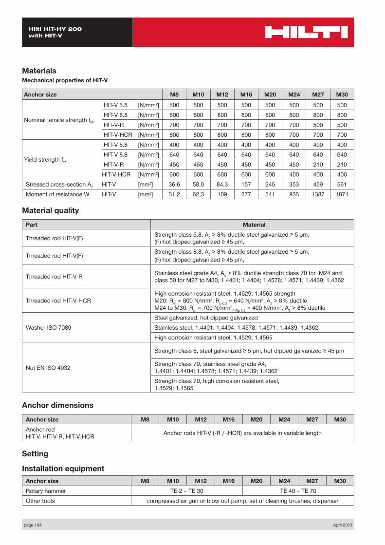
MaterialsMechanical properties of HIT-V
Anchor size M8 M10 M12 M16 M20 M24 M27 M30
Nominal tensile strength fuk
HIT-V 5.8 [N/mm²] 500 500 500 500 500 500 500 500HIT-V 8.8 [N/mm²] 800 800 800 800 800 800 800 800HIT-V-R [N/mm²] 700 700 700 700 700 700 500 500HIT-V-HCR [N/mm²] 800 800 800 800 800 700 700 700
Yield strength fyk
HIT-V 5.8 [N/mm²] 400 400 400 400 400 400 400 400HIT-V 8.8 [N/mm²] 640 640 640 640 640 640 640 640HIT-V-R [N/mm²] 450 450 450 450 450 450 210 210
HIT-V-HCR [N/mm²] 600 600 600 600 600 400 400 400Stressed cross-section As HIT-V [mm²] 36,6 58,0 84,3 157 245 353 459 561Moment of resistance W HIT-V [mm³] 31,2 62,3 109 277 541 935 1387 1874
Material quality
Part Material
Threaded rod HIT-V(F) Strength class 5.8, A5 > 8% ductile steel galvanized ≥ 5 μm, (F) hot dipped galvanized ≥ 45 μm,
Threaded rod HIT-V(F) Strength class 8.8, A5 > 8% ductile steel galvanized ≥ 5 μm,(F) hot dipped galvanized ≥ 45 μm,
Threaded rod HIT-V-R Stainless steel grade A4, A5 > 8% ductile strength class 70 for M24 and class 50 for M27 to M30, 1.4401; 1.4404; 1.4578; 1.4571; 1.4439; 1.4362
Threaded rod HIT-V-HCRHigh corrosion resistant steel, 1.4529; 1.4565 strength M20: Rm = 800 N/mm², Rp 0.2 = 640 N/mm², A5 > 8% ductile M24 to M30: Rm = 700 N/mm², Rp 0.2 = 400 N/mm², A5 > 8% ductile
Washer ISO 7089Steel galvanized, hot dipped galvanizedStainless steel, 1.4401; 1.4404; 1.4578; 1.4571; 1.4439; 1.4362High corrosion resistant steel, 1.4529; 1.4565
Nut EN ISO 4032
Strength class 8, steel galvanized ≥ 5 μm, hot dipped galvanized ≥ 45 μm
Strength class 70, stainless steel grade A4, 1.4401; 1.4404; 1.4578; 1.4571; 1.4439; 1.4362Strength class 70, high corrosion resistant steel, 1.4529; 1.4565
Anchor dimensions
Anchor size M8 M10 M12 M16 M20 M24 M27 M30Anchor rod HIT-V, HIT-V-R, HIT-V-HCR Anchor rods HIT-V (-R / -HCR) are available in variable length
Setting
Installation equipmentAnchor size M8 M10 M12 M16 M20 M24 M27 M30Rotary hammer TE 2 – TE 30 TE 40 – TE 70Other tools compressed air gun or blow out pump, set of cleaning brushes, dispenser
April 2013 page 105
Hilti HIT-HY 200 with HIT-V
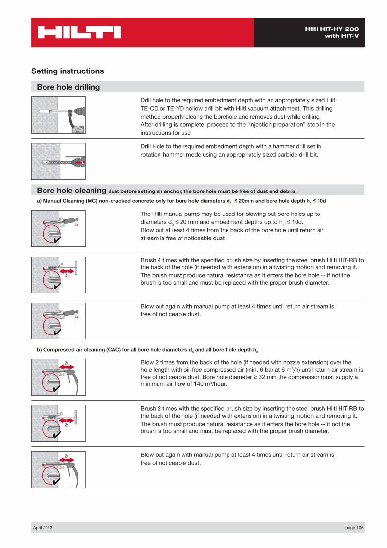
Setting instructions
Bore hole drillingDrill hole to the required embedment depth with an appropriately sized HiltiTE-CD or TE-YD hollow drill bit with Hilti vacuum attachment. This drillingmethod properly cleans the borehole and removes dust while drilling.After drilling is complete, proceed to the “injection preparation” step in theinstructions for use
Drill Hole to the required embedment depth with a hammer drill set inrotation-hammer mode using an appropriately sized carbide drill bit.
Bore hole cleaning Just before setting an anchor, the bore hole must be free of dust and debris.
a) Manual Cleaning (MC) non-cracked concrete only for bore hole diameters d0 ≤ 20mm and bore hole depth h0 ≤ 10d
The Hilti manual pump may be used for blowing out bore holes up todiameters d0 ≤ 20 mm and embedment depths up to hef ≤ 10d.Blow out at least 4 times from the back of the bore hole until return airstream is free of noticeable dust
Brush 4 times with the specified brush size by inserting the steel brush Hilti HIT-RB to the back of the hole (if needed with extension) in a twisting motion and removing it.The brush must produce natural resistance as it enters the bore hole -- if not the brush is too small and must be replaced with the proper brush diameter.
Blow out again with manual pump at least 4 times until return air stream isfree of noticeable dust.
b) Compressed air cleaning (CAC) for all bore hole diameters d0 and all bore hole depth h0
Blow 2 times from the back of the hole (if needed with nozzle extension) over the hole length with oil-free compressed air (min. 6 bar at 6 m³/h) until return air stream is free of noticeable dust. Bore hole diameter ≥ 32 mm the compressor must supply a minimum air flow of 140 m³/hour.
Brush 2 times with the specified brush size by inserting the steel brush Hilti HIT-RB to the back of the hole (if needed with extension) in a twisting motion and removing it.The brush must produce natural resistance as it enters the bore hole -- if not the brush is too small and must be replaced with the proper brush diameter.
Blow out again with manual pump at least 4 times until return air stream isfree of noticeable dust.
page 106 April 2013
Hilti HIT-HY 200 with HIT-V
Setting instructions
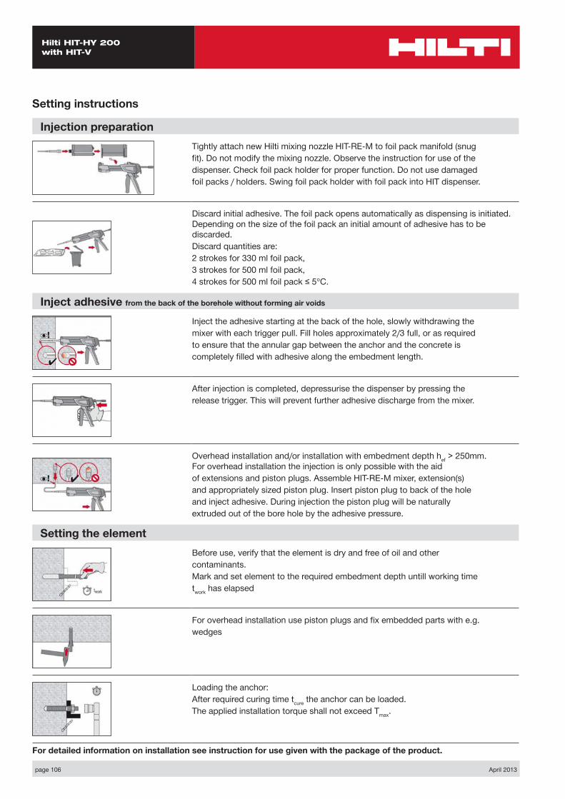
Injection preparationTightly attach new Hilti mixing nozzle HIT-RE-M to foil pack manifold (snugfit). Do not modify the mixing nozzle. Observe the instruction for use of thedispenser. Check foil pack holder for proper function. Do not use damagedfoil packs / holders. Swing foil pack holder with foil pack into HIT dispenser.
Discard initial adhesive. The foil pack opens automatically as dispensing is initiated. Depending on the size of the foil pack an initial amount of adhesive has to be discarded.Discard quantities are:2 strokes for 330 ml foil pack,3 strokes for 500 ml foil pack,4 strokes for 500 ml foil pack ≤ 5°C.
Inject adhesive from the back of the borehole without forming air voids
Inject the adhesive starting at the back of the hole, slowly withdrawing themixer with each trigger pull. Fill holes approximately 2/3 full, or as requiredto ensure that the annular gap between the anchor and the concrete iscompletely filled with adhesive along the embedment length.
After injection is completed, depressurise the dispenser by pressing therelease trigger. This will prevent further adhesive discharge from the mixer.
Overhead installation and/or installation with embedment depth hef > 250mm. For overhead installation the injection is only possible with the aidof extensions and piston plugs. Assemble HIT-RE-M mixer, extension(s)and appropriately sized piston plug. Insert piston plug to back of the holeand inject adhesive. During injection the piston plug will be naturallyextruded out of the bore hole by the adhesive pressure.
Setting the elementBefore use, verify that the element is dry and free of oil and othercontaminants.Mark and set element to the required embedment depth untill working timetwork has elapsed
For overhead installation use piston plugs and fix embedded parts with e.g.wedges
Loading the anchor:After required curing time tcure the anchor can be loaded.The applied installation torque shall not exceed Tmax.
For detailed information on installation see instruction for use given with the package of the product.
April 2013 page 107
Hilti HIT-HY 200 with HIT-V
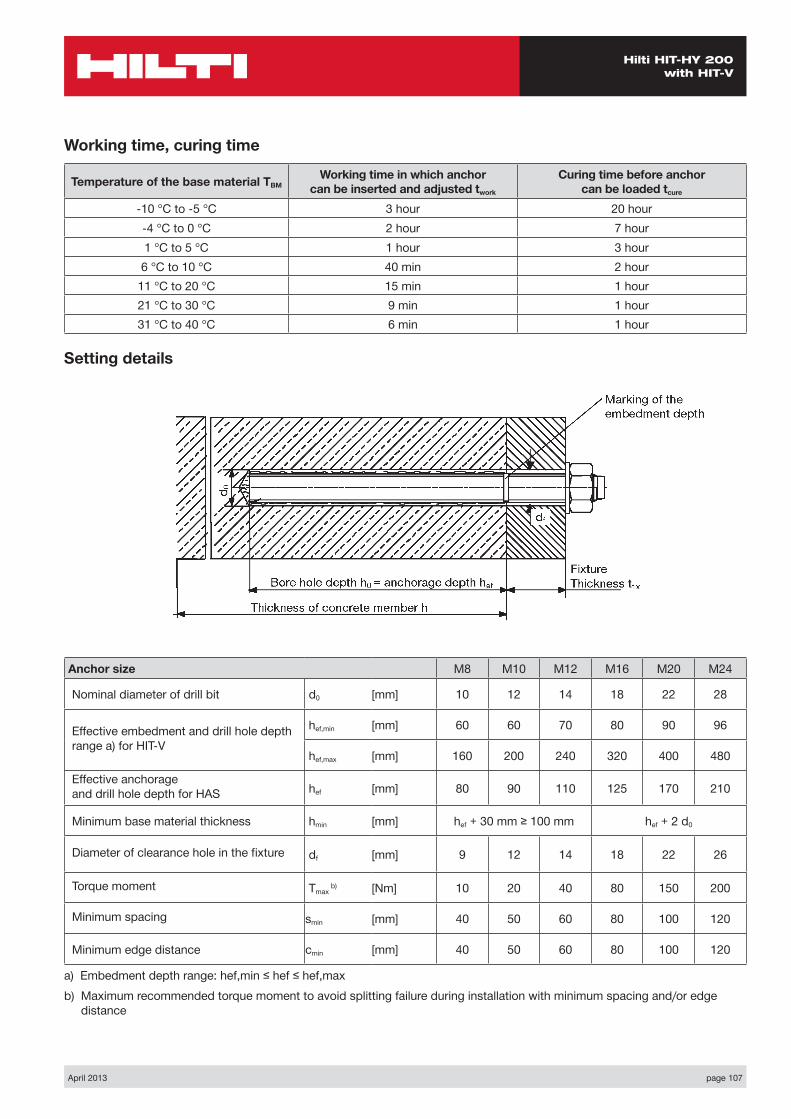
Anchor size M8 M10 M12 M16 M20 M24
Nominal diameter of drill bit d0 [mm] 10 12 14 18 22 28
Effective embedment and drill hole depth range a) for HIT-V
hef,min [mm] 60 60 70 80 90 96
hef,max [mm] 160 200 240 320 400 480
Effective anchorage and drill hole depth for HAS hef [mm] 80 90 110 125 170 210
Minimum base material thickness hmin [mm] hef + 30 mm ≥ 100 mm hef + 2 d0
Diameter of clearance hole in the fixture df [mm] 9 12 14 18 22 26
Torque moment Tmax b) [Nm] 10 20 40 80 150 200
Minimum spacing smin [mm] 40 50 60 80 100 120
Minimum edge distance cmin [mm] 40 50 60 80 100 120
a) Embedment depth range: hef,min ≤ hef ≤ hef,max b) Maximum recommended torque moment to avoid splitting failure during installation with minimum spacing and/or edge
distance
Setting details
Working time, curing time
Temperature of the base material TBMWorking time in which anchor
can be inserted and adjusted twork
Curing time before anchor can be loaded tcure
-10 °C to -5 °C 3 hour 20 hour-4 °C to 0 °C 2 hour 7 hour1 °C to 5 °C 1 hour 3 hour6 °C to 10 °C 40 min 2 hour
11 °C to 20 °C 15 min 1 hour21 °C to 30 °C 9 min 1 hour31 °C to 40 °C 6 min 1 hour