Analytical formulation of small signal stability analysis ...
21
SSdhan6, Vol. 18, Part 5, September 1993, pp. 869-889. Printed in India. Analytical formulation of small signal stability analysis of power systems with nonlinear load models RAJEEV K RAN JAN, M A PAI and P W SAUER University of Illinois, Department of Electrical and Computer Engineering, Urbana, IL 61801, USA Abstrnct. It is now recognized that both load dynamics and generating unit dynamics contribute significantly to the limitation of loadability of power systems. In this paper, we take a static nonlinear load representation and different combinations of machine and exciter dynamic models to develop a comprehensive linearized model to study small signal stability. In particular we monitor the Hopf bifurcation instability and through participation factor analysis we identify the relevant state variables. Keywords. Small signal stability; Hopf bifurcation; nonlinear load models; power system stability. 1. Introduction There is extensive literature on small signal analysis in power systems (Padiyar et al 1981; Kundur et al 1990; Sauer & Pai 1990; Wang & Semlyen 1990), and it is the principal tool to study both low-frequency oseiUations and voltage stability. In the literature these two phenomena are treated separately. In this paper, we take a unified approach and attempt to look at the dependence of these two phenomena on the parameters of the system, which are the loads (nonlinear dependence on voltage) and modelling of the generating unit (machine and exciter). Use of participation factor is helpful in identifying state variable participation in a critical mode. We also extend the results of an earlier paper (Sauer & Pai 1990) regarding the role of the system Jacobian, algebraic Jacobian and the load flow Jacobian on voltage collapse. To illustrate our studies both 3-machine and 10-machine cases are studied but the research grade program developed is general enough to handle larger systems. The small-perturbation behaviour of the power system in the vicinity of a steady- state operating point can be described to first order by a set of linear, time-invariant (LTI) differential equations in the state space form = Ax + Bu. The N-dimensional state vector x represents the perturbations of the system state variables from their nominal values at the given operating condition, and the vector u represents perturbations of the system inputs such as voltage reference, desired real power or load demands. The numerical values of the matrices A and B depend on 869
Transcript of Analytical formulation of small signal stability analysis ...

SSdhan6, Vol. 18, Part 5, September 1993, pp. 869-889. �9 Printed in India.
Analytical formulation of small signal stability analysis of power systems with nonlinear load models
RAJEEV K RAN JAN, M A PAI and P W SAUER
University of Illinois, Department of Electrical and Computer Engineering, Urbana, IL 61801, USA
Abstrnct. It is now recognized that both load dynamics and generating unit dynamics contribute significantly to the limitation of loadability of power systems. In this paper, we take a static nonlinear load representation and different combinations of machine and exciter dynamic models to develop a comprehensive linearized model to study small signal stability. In particular we monitor the Hopf bifurcation instability and through participation factor analysis we identify the relevant state variables.
Keywords. Small signal stability; Hopf bifurcation; nonlinear load models; power system stability.
1. Introduction
There is extensive literature on small signal analysis in power systems (Padiyar et al
1981; Kundur et al 1990; Sauer & Pai 1990; Wang & Semlyen 1990), and it is the principal tool to study both low-frequency oseiUations and voltage stability. In the literature these two phenomena are treated separately. In this paper, we take a unified approach and attempt to look at the dependence of these two phenomena on the parameters of the system, which are the loads (nonlinear dependence on voltage) and modelling of the generating unit (machine and exciter). Use of participation factor is helpful in identifying state variable participation in a critical mode. We also extend the results of an earlier paper (Sauer & Pai 1990) regarding the role of the system Jacobian, algebraic Jacobian and the load flow Jacobian on voltage collapse. To illustrate our studies both 3-machine and 10-machine cases are studied but the research grade program developed is general enough to handle larger systems.
The small-perturbation behaviour of the power system in the vicinity of a steady- state operating point can be described to first order by a set of linear, time-invariant (LTI) differential equations in the state space form
= A x + Bu.
The N-dimensional state vector x represents the perturbations of the system state variables from their nominal values at the given operating condition, and the vector u represents perturbations of the system inputs such as voltage reference, desired real power or load demands. The numerical values of the matrices A and B depend on
869

870 Rajeev K Ranjan, M A Pal and P W Sauer
I
l
- 1 m+l ~ - -
= 2 m+2
Transmission �9 Network �9
: m n .4~. .
--1
--1
q Figure 1. system.
A genera l m-machine , n - b u s
[E.,,+(X.,,_X.)Jo,+jE;ja~'.-"'=)~ >
Figure 2.
I t , {/ ~, + j /q , ) e~(,~,- ,,/2)
+
(Va + jVei)e.t(~"-"/2) = ViiMe'
Synchronous machine two-axis model dynamic circuit (i = 1 . . . . . m).
iX'~ R,~ (la~ +Jlq~) e/(~'- ./2)
4.
[ (Xqi- X'ai)lqi + JEqi]d{~'-""~) ( > (Va,. + jVq,.) e iC~'-*/2> = Viei6~
m
I
Figure 3. Synchronous machine flux-decay model d y n a m i c circuit (i = 1 . . . . , m).
V ~ KA I I + sT̂ -I
Vt
Figure 4.
S(Efd)
' F K~+ sT~
, sKF
I*sTF
IEEE-typr 1 exciter model.
rnd

Small signal stability analysis of power systems 871
Vt
i "*" sTA
Figure 5. Static exciter model.
the operating condition as well as on the system parameters. The whole analysis starts with a systematic derivation of a linear model for an n-bus m-machine nonlinear differential algebraic system with nonlinear voltage-dependent loads at the network buses (figure 1). The model so obtained is flexible enough to study both low-frequency oscillations and voltage stability problems. For the former study the system A matrix and its eigenvalues are readily obtainable for any given load model. The influence of parameters such as exciter gain and loads can be studied very easily. It is shown that the appearance of the electromechanical mode of oscillation or exciter mode oscillation depends critically on the modelling of the machine and the excitation system. For voltage stability analysis, we progressively load the system at a bus or set of buses and, at each loading, monitor the eigenvalues of the linearized system.
The machine is modelled by either a two-axis or a flux decay model, and the excitation system by either an IEEE-type I or a static exciter model. Thus potentially we have four types of generating unit models. We derive two linearized models, namely, a two-axis, with IEEE-type 1 exciter (model A) or flux decay with static exciter (model B). The synchronous machine representation and the exciter representations are shown in figures 2-5. One could also consider a two-axis machine model with a static exciter (model C) and a flux decay model of the machine with IEEE-type 1 exciter (model D).
2. Various mathematical models
The mathematical model consists of differential equations pertaining to machine and exciter dynamics and algebraic equations corresponding to the stator and network equations.
2.1 Model A (two-axis model with tEEE-type 1 exciter)
The differential equations of the machine and the exciter are given as in Sauer & Pal (199i) where the various symbols are defined.
2.1a Differential equations:
d6~ dt
do~i T~i E' ' I = ~ - - [ qi - - X a l l dI] qi
dt M~ M(
(i)
[E'ai + X'qilqi]ldi Di((o( -- cO), (2)
Mi M i
!
dEqt = E' (Xai - - X ' d i ) I d i Efd i __ ~ t__ - + i r I ' dt T do i "I'~o I ,roi
dE~i E' ' ~ , _ ,~i + T' ( X r x q i ) '
dt T r qot
(3)
(4)

872 Rajeev K Ranjan, M A Pal and P W Sauer
dE.r~ KE~ +S~. V m = _ _ _ ( E e l ) E m + (5) dt
dVx'dt VR' T4~ ~ - - E f , u + ~ ( V , , y , - E) , = - - E +K'4~R$~ K'4~Kn~T~ Tn~ (6)
d R r i = - Rr~. + Kr~ Eydi, for i = 1 . . . . , m. (7) dt Tr, (T~) 2
2.1b Stator algebraic equations: The stator a lgebraic equat ions are
E~, - E sin(~, - 03 - Rfl~, + X'qd,, = O, (8)
E'.~, - V~ cos(f` t - 0 ) - R,,1q~ - X'd, Ij, = 0, for i = 1 , . . . , m. (9)
These algebraic equat ions can be represented as a current dependen t voltage source at the generator buses (figure 2).
2.1c Network equations: The network equat ions are
l~l Vt sin(6 ~ - 0~) + lq~ V~ cos (3 , - 0~) + PL~(V~) II
- E v,v, k - - I
l ,i Vi cos(~5 ~ - 0 ) - I , , V~ sin (t~ - 0i) + QLI(Vi)
- ~'. V~ V k Y~k sin(O, - 0 k - ~,k) = O, k = l
N
P,.gE)- E v,v k = l
I1
Q L , ( V ) - ~ V, V~ Y~ sin(O,-O~-e,k)=O , k = l .
(:o)
i = l . . . . ,m, (11)
(12)
for i = m + 1,... ,n. (13)
2.2 Model B (flux decay model and fast exciter)
If the damper winding time constants T' ~o~ are very small, then use of s ingular perturbations (Sauer & Pai 1991) makes the E~,, dynamics very fast so tha t (4) becomes an algebraic equation:
o = - + ( x , - x ' , , ) l q , ,
i.e., E' X' ~i ~ ( X ~ t - q~)I~i- (14)
The differential and algebraic equations of the two-axis model will be modified by substituting (14) in (2), (8) and (9). Moreover, for a simple and fast exciter, the transfer function between (V, ef. ~ - Vt) and Er~ , is represented by a single t ime constant , so that the exciter model becomes
Tal(dE yaffdt) = - E yal + KAt(V,,f., - Vl). (15)
The overall flux decay model is represented by the following set of equations.

2.2a
Small signal stability analysis of power systems 873
Differential equations:
db~ - - = o~i - cos, (I 6) dt
do9 i _ T~i ' I _ - X ' Di(o) i - o)s) Eqi qi (Xql di) l d~Iqi (17) dt Mi Mi Mi Mi '
dE'~ Eiq ~ (Xai -- X'ai). Efd i d~ = - r~o, r-';~, '~' + r'~o,' (18)
(V~,r. , - V,), for i = 1 . . . . . m. (19) dt Tai T m
2.2b Stator algebraic equations: The stator algebraic equations are
sin (3,- 0;) + R~Id, -- Xq~lq~ = 0, (20)
E'qi -- V/cos(3 i - Oi) - Rs i lq i - X'd}I,, = 0, for i = 1, . . . , m. (21)
The equivalent circuit for these equations is shown in figure 3.
2.2c N'etwork equations: The network equat ions are the same as (10)-(13).
2.3 Model C (two-axis model with fast exciter)
In this model we have (1)-(4) as the differential equations for the machine and (8)-(13) as the algebraic equations. The exciter is represented by (15).
2.4 Model D (,flux decay with IEEE-type I exciter)
The differential equations are (16)-(18) and (5)-(7). The algebraic equations are (20)-.-(21) and (10)-(13).
3. Linearization of model A
Linearizing the differential equations (1) to (7) we have
dA/) z = A o ) i , ( 2 2 )
dt
_ E ' ' I X ' dA(.oi 1 ATMi_ qi~ i + xdi el~ + ~d,,OAl _ I_-~AE'. dt M~ M i q Mi qi ' " di M i Mi q'
E'diO Ai qi l ~io Ai X ' qi[qio A l o, - ', , - - - - A o J i ,
-~, ~, I~'~176 x ' M i di M i M~ q M~
daG, _ at;, (x.,-x'~,)a~.,_ aEz~, !
dt T' T' T' doi doi doi (23)
OAG, AG, (X ~,- G,) - - + A I ~ i , ( 2 4 )
dt T' T' doi qo.i

874 Rajeev K Ranjan, M A Pal and P W Sauer
E AV , dA--sdJ-= + Tr----- [ ' (25)
daV~, AVRt KAtKFi AE Ka, = TAt +KA'ARFt - - - - KatAV, + TA t'Av,~f, t'(26)
T u TA t TF t yet T, u
dAR w AR w Kl:t = + AEsa i, for i= 1, ..,m, (27)
dt TF, ~
where fi(Ey~i,) = - [Ke~ + Esd~o ASr(E/dio ) + SE(Efd,)]/Tev Writing equations (22) through (27) in matrix notation we obtain,
A~b, A ' ae~ AEsds
B
0
0
0
0
0
0
0
1 0 0 0 0 0
Di _ I~~ Idi o 0 0 0 M i -lift s M s
1 1 0 0 0 0
T' T' dot doi
1 0 0 0 0 0
T' qol
1 0 0 0 ft(Efdio) 0
0 0 0 KAtKrt 1
0 0 0
TAt L, L,
KFt 0 (T~,) 2
K.At
rat 1
- . d
w
AcS~
Ar s
AE'q~ AE'd~
AE m AVR, ARrt
m m
+
0
I ' X' E' q~o(Xai- ~i)- .fo M~
( X di - X'd3
T' dol
0
0
0
0
m
dio ( X .i - X q3 - E'o~ Mi
0
(Xqi - X ' , )
T'qo,
0
0
[ Al~l ] Alqi _]

Small signal stability analysis of power systems 875
+
B N
0 0
0 0
0 0
0 0
0 0
0 KAi
_o o_.
- 0
Mi
0
o ~ViJ
0
0
_0
O] 0
0
KAi L,
Denoting LAI~_I = Alg~, LAE-I
[ ATMi 1 i= 1,2, m.
AVes , , J ' " " '
and LAV,,'r,,r = Au~,
(28)
we obtain,
AX l = Az~AX i + A2iAIg i + Aa~AVg i+ EiAui, for i = l . . . . ,m. (29)
For the m machine system, (29) c a n be expressed as
A)( = A t A X + A2AI ~ + A3AVg + EAU, (30)
where A~, A2, Aa, and E are block diagonal matrices. We now linearize the stator algebraic equations (8) and (9) to get
AE'di - sin(6~o - O~o)AV~ - V~o COS(6~o - 0,,)A6 i + V~oCOS(61o - Oio)AO~
- R~tAlai + X'qlAlqt = 0, (31)
AE'qi - cos(~io - 0~o)AV~ + Kosin(~Sio - 0~o)A6 ~ - VtoSin(6~o -. O~o)AO ~
-R , IA I ,~ I -X ' , ,A Id~=O, i = 1,2 . . . . ,m. (32)
Writ ing (31) and (32) in the matr ix form, we have
[-~ocos(~,o-0,~ o o 1 o o Ool Vio sin(6~~ O~o) 0 1 0 0 0
- m
Ac5 i
Aa~ i
AE'q~
AE':~
AEydi A VR~ ARri
A~J
-sin( ,o-0,ol-] + qi + -x'~l -R, , L~Iqi_l L- V~~176 cos(8io-0,o)J
= 0 , i = 1 ,2 , . . . ,m. (33)

876 Rajeev K Ranjan, M A Pal and P W Sauer
R e w r i t i n g (33) we get
0 = BltAX i + BaiAIr + B3iAVg ~, i = 1,..., m. (34)
In c o m p a c t no ta t ion , (34) can be writ ten as
0 = B1AX + B2AI~ + B3AVg, (35)
whe re BI, Bz, and B3 are block d iagonal matrices. L inear iz ing the ne twork equat ions (1(3) a n d (1 I), which per ta in to generators, we obta in
V~o sin(6~o - O~o)AI,, + Idto sin(~io - '01o)AV ~ + Id~ o V~o cos(5~o - 0~o)A6 i
- la~ ~ V~o cos (~ ,o - 0~o)A0~ + V~o c o s ( ~ o - O~o)AIi + I~o c o s ( ~ i o - O~o)AV~
- - f ~= Vk~176176 1
- ~~ E [ ~ cos(O,o-O~o-~)]~v~ k = l
h" [ V~~ Z Vk~ Yik sin(Oi~ -- OJ:o - ~ ] l
-- V,, ~ [Vko Y, ksin(O,,- 0,o- a,k)]A0k + AP~,(V~)= 0. (36) k = l
V~~ cos(6~o -- O~o)Al di + I,m cos(6io -- Oio)A V ~ - I ,~o V~o sin(6to - 0,o)A3i
+ I,,o V~,, sin(6~o - O~,)A0g -- V~ sin(f1~ - 81o)Al,~ i - lq~o sin(hio - 0~o)A V~
- - l#l o Vio cos(6io - Oio)A5 ~ + I qt o Vio cos(5io - O~o)AOI
--[k=~ Vk~ Y'~ sin(O'~ --Ok~ lAV'
[ Y~ sin(O,o - O~, - o~ ) ] A V~ - Vio Z V~, Yl~cos(Or~ AO, k = l =
wI
+ v,o ~ IVy. Y,~cos(O,o--O,-o:,k)]AO k +,~Q,.,(v,) = o. k , : I
r
R e w r i t i n g (36) and (37), we obtain
i = 1 .2 , . . . ,m.
(37)
[ I,,. v, ooos(,,o-o,~ V, osin(*,o- O,o1 0 o o o o o] L -Ia~oV~sin(Sio-Oio)-Iq~oV~oCOS(~-Oto) 0 0 0 0 0 o J
AE'q~ .4- L_IV~osin(6'~176176176176 LAl'tjc~176176 AE'~, [ V, o eos(~,o-O,~ - V,o AE f ,li AVe,
I_A RF

Small signal stability analysis of power systems 877
+
lqio V/o sin(cS~ o - Oio )
-- l dt ~ VioCOS(~io -- Oio )
+ Vio ~ Vko Yiksin(Oio--Oko--Ctik) -- k=l k=l
I~o V~o sin(3~o - 0~o) + Iq~ o V~o cos(3~o - 0~o) tJ
- V , o ~., Vko Y, kCOS(Oio--Oko--aik) k = l
ld~o sin(3io - 0io )
+ lq~o cos(6~o - 0~o )
Vko Y~ cos(0,o - 0~o - %,)
-- Vio Yll COS O~ii
l aio COS(3to -- Oio ) - I q i o sin(6io -- 0io )
- Z Vko Yik sin(O~o -- Oko - ~ k = l
AOI] [ -- Vio Vko Yik sin(Oio -- Oko -- %,) AV, J + k=l ~ Vio V~o Y, kCOS(Oio--Oko--~Zlk) :#i
r APLi(Vt) ] + LAQ.(v3J + j-~m+ 1
- V,o Y,,co~(O,o-o~o-~,~)][Ao~ 1 - g~o Ylksin(O~o- Oko-~ik)_JI_AV~
" [ - Vio Vj,, r u s i n ( O , o - O ~ o - % ) - Vio Yucos(O,o-Ojo-aU) 1 Vio V~o Yi.i c~ - 0jo - ctu) V~o Yij sin(Oio - O jo - oqj) _]
A v j j = o. (38)
Rearranging in matrix notation
0 = CxiAXI + C2iAIgi + [C3i 1 C3i2"'" C3i m]
+ [C4i,~C,,i.,.+l
aV, m+,] E ~+2! �9 .-C,,.]~ - / +
L ~,~',.. J
A v- I
-APLi(~) ] , AQ, . (V, ) /
fo r /= 1,...,m.
(39)
For m machines, (39) can be written in matrix notation as
" q LAx~_I "q LAi.._I C4, lm + 2
~ 1 7 6 1 7 6
~ 1 4 9 1 7 6
c" 1 q

878 Rajeev K Ranjan, M A Pal and P W Sauer
v,7* [
Rewriting (40) as
"APLt (Vi)- AQL~(V,)
+ :
APL.(V.) (40)
0 = CIAJ( + C2z~lg + CsAVg + C,,AV z + AS~.g(V). (41)
Note that C1, C2 are block diagonal whereas C3, C4 are full matrices. Linearizing network equations (12) and (13) for load buses
n
k = l
I I
- ~o ~ [Vko Y~kSin(O,~.--O~o--Ct,k)]hO k, k--1
(42)
- v,~ ~ Ey,,,sin(O,o-O~o-,,,,,,)]a K k = l
-t- V~o ~_. [Vko Y~kSin(O,o--Oko--Ot,k)']AOk, i=m-4- 1,...,n. (43) k = l
Rewriting (42) and (43) we obtain
L~.~2L~(~ J
j=l L V~o V~o ~jcos(0 , . - 0jo - % ) - V~~ gosin(0~~ - 010 - % ) J LAVj_I
+ l k=,~-i Vio Vko Y',kCOS(O,o--Ok~ -- Vio Y~kSin(O,~ Oko-- %) J L a ~

Small signal stability analysis of power systems 879
+
E Vto Vko Yi, sin(O,o--Oko--a,k) - s k~=l k = l
v~o r, kcos(O,o--Oko--~,k)-- V,o Y,,
n n
- V,o Z V~o r, kcos(O,o-O,,o-~,,,) - Y k= l / = 1
k--
Vko Yik sin(Oio - Oko - alk)
Writing the above equation for all load buses in matrix notation, we obtain
=
Le,.,,+,(v,~+,? AQLm+I(Vm+I)
~Q, .(vo)
r Dl.,,,+l.1 Dtm+i.2 ." Dl,,,+l,,,q ['~Vgl l + . , , . . " " [ / o2
i A0/].
(44)
+ t , l . ,m + 2 " D2,m+i,n
D2"+2'r~+t D2'm+2'm+2 "i" D2'"~ +2' VtY + �9
(45)
Rewriting (45) in a compact notation we obtain
O=ASL,(V) + D~AVg + D2AV u (46)
Note that D 1 and D 2 are full matrices. Rewriting (30), (35), (41) and (46) together, we obtain
A~( = A t A X + A2AI o + A3AVg + EAU,
O= Bt AX + B2AI o + B3AV,,
0 = C 1AX + C2AI r + C3AVg + C4AVL + ASLg(V),
0 = DI AV o + D2AVI + ASL~(V).
(47)
(48)
(49)
(50)
This is the general comprehensive model of the differential-algebraic type to study both steady state and voltage stabilities with any type of nonlinear voltage dependent loads. The network structure is preserved and so are the stator algebraic equations for each machine�9 Equations (47)-(50) are equivalent to the model in Sauer & Pai (1990) except that a machine angle is not introduced as reference. This model is quite general and can easily be expanded to include frequency or V dependence at the load buses, PSS tap-changer dynamics or FACTS devices. This will only augment (47)-(50) by either algebraic or differential equations. In the above model, AIg is not of interest in most cases. Hence, eliminating AIg from the set of equations (47), (48)

880 Rajeev K Ranjan, M A Pal and P W Sauer
and (49) we get the following reduced set of equations,
where
and
a~? = (A~ - A 2 ~ x & ) A X + (A 3 - A~B~ ~ B3)AV . + EAU,
0 = KEAX + K 1A V + C,,A ~ + AS,.a(V),
O= D~AV o + DzAV t + ASzt(V),
[C 3 - C2B~IB3- I A__ K1 '
[C 1 _ C2B~IB1-] A= K2"
(5I)
(52)
(53)
(54)
More compactly, (51)-(53) can be put in the form
(ss)
where AV= LAV~J and AS~ LASs.~ J" Reorder the variables in the vector A V =
[AVg]suchthatthenewvectoris[Azr,Avr]=[AO~ AV~ . AVmIAO2,A03,. AOn, Art . . . . . " "
AV,, + 1,..., A I/,]. In this reordering of algebraic variables Av represents those variables appearing in the standard load flow equations and Az the remaining ones in A V. Also
[ASz. ] reorder the variables in [-AS~ t J to conform similarly so that AS[ = [ A P L t , A Q r . t , . . . .
AQL,,IAPL2,APLa .... ,APL,,AQL,,+I,...,AQL,]=[AS~IAS~']. We carry out one more operation on the set of equations (51 )-(53). In any rotational system, the reference for angles is arbitrary. The order of the dynamical system in (51) is 7m, and can be reduced to (7m - 1) by introducing relative rotor angles (Sauer & Pal 1990). Selecting 3t as the reference, we have
3'~=fi1--~5 l, i=2,3, . . . ,m, I
di 1 =0,
~'i=o~i-o.~l, i=2,3 .... ,m,
~'1 =0,
01=0i--c5 I, i= l , 2 , . . . , n .
This implies that the differential equation corresponding to 6x can be deleted from (55) and also the column corresponding to A3a in A1 and Bt. Moreover, the entries corresponding to #~, f = 2, 3,..., m will bring necessary changes in ,4~. We denote the reduced state vector as Ax. We thus have the new differential-algebraic (DAE) system as
B~ + + AU. (56) = B= /
This model is slightly different from that in Sauer & Pai (1990) in the sense that we

Small signal stability analysis of power systems 881
allow for voltage dependency for the loads in the vectors AS1 and AS 2. For the constant power case, both ASI and AS 2 are = 0. Otherwise, ASli= ASu(K ) and ASz~ = AS2i(Vi). For a given voltage-dependent load, AS~i(Vi) and AS2i(K ) can be computed. Only the appropriate diagonal elements of B2, C2 and C 3 will be modified and we obtain the system
= /~1
1
Now (~3 is the load flow
Jacobian. The system A
B2 /~3 z + AU.
e L,',ol LOj
Jacobian Jc~ and C2
matrix is obtained as
(57)
C'3 = J,te defined as the algebraic
where A~ = AsrsAx + EAU, (58)
A = 3 I-[A2A3][JA~] -1 C1 "
This is the model used in studying low frequency oscillation, steady state stability and voltage stability. In the next section we examine the effects of increased loading on the eigenvalues of As, and the determinants of JAE and JLF for (a) constant power case, (b) constant current case, and (c) constant impedance case for each of the models A, B, C, and D. Thus we do the parametric study regarding load and generating unit models on small signal stability.
The linearized equations for models B, C, and D can be derived along the same lines and hence are omitted.
4. Identification of critical modes: Participation factor method
Due to the large size of the power system, it is often necessary to construct reduced- order models for dynamic stability studies. The appropriate definition and determination as to which state variables significantly participate in the selected modes become very important. This requires tools for identifying state variables that are significant in producing the selected modes. It is natural to suggest that the significant state variables for an eigenvalue 2i are those that correspond to large entries in the eigenvector vu But the entries in the eigenvector are dependent on the dimensions of the state variables, which are, in general, incommensurable (for example, angles, velocities, and flux). Verghese et al (1982) have suggested a related but dimensionless measure of state variable participation (henceforth called participation factors). If vl and w~ represent the right- and left-hand eigenvectors, respectively, for the eigenvalue 2~ of the matrix A, then the participation factor (PF) measuring the participation of the kth state variable xk in the ith mode is defined as
Pki = WkiOkl"
This quantity is dimensionless and hence invariant under changes of scale of the variables. We can think of Vki as measuring the activity of x k in the ith mode, and
882 Rajeev K Ranjan, M A Pai and P W Sauer
wk~ as weighting the contribution of this activity to the mode. The step-by-step procedure for the calculation of P~ is as follows:
(1) For the given A ys, the eigenvalues 2'is and the right- and the left-hand eigenvectors ('~z and ff~, respectively) are calculated, for i= 1, 2 . . . . , ( 7 m - 1).
(2) For a given eigenvalue 2t the corresponding PF are calculated as follows: (a) The normalization constant r is calculated by finding Z~t= 1 abs(~t~)abs(-Wtl)
where N = 7m - 1. (b) Then PFi~ = abs(Ylij)abs(~j)/d~ ~.
5. Studies of parametric effects
5.1 Effect of loading
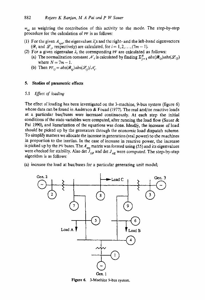
The effect of loading has been investigated on the 3-machine, 9-bus system (figure 6) whose data can be found in Anderson & Fouad (1977). The real and/or reactive loads at a particular bus/buses were increased continuously. At each step the initial conditions of the state variables were computed, after running the load flow (Sauer & Pai 1990), and linearization of the equations was done. Ideally,, the increase of load should be picked up by the generators through the economic load dispatch scheme. To simplify matters we allocate the increase in generation (real power) to the machines in proportiofi to the inertias. In the case of increase in reactive power, the increase is picked up by the PV buses. The Asy s matrix was formed using (55) and its eigenvalues were checked for stability. Also det Jzr and det JaE were computed. The step-by-step algorithm is as follows:
(a) increase the load at bus/buses for a particular generating unit model;
Gen. 2
Load A ~ 1
~ Load C
�9 L
. _ f
Gen. 1
) Q
Load B
G
Gen. 3
Figure 6. 3-Machine 9-bus system.

Small sional stability analysis of power systems 883
(b) if the real load is increased then distribute the load amongst various generators in proportion to their inertias;
(c) run the load flow; (d) stop, if load flow fails to converge; (e) compute initial conditions of the state variables; (f) linearise the differential equations and compute the various matrices; (g) compute det Jzr, det .IA~, and the eigenvalues of Asr~; (h) if A y, is stable then go to step (a); (i) identify the states associated with the unstable eigenvalue (s) of Asy s using the
participation factor method and go to step (a).
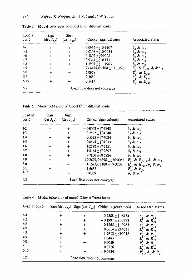
For the 3-machine case all the four generating units are studied. The results are summarized in tables (1)-(4) for the models A-D. For the static exciter, a gain of K a = 50 was assumed.
5.2 Effect of K a
It was found that for model A, the increase in KA alone did not lead to any instability. The stabilizing feedback in IEEE-type 1 exciter was removed and then an increase in K A led to instability for this model as well. For model B a sufficient increase in KA led to instability even for a nominal load.
5.3 Effect of type of load
The effect of different types of voltage-dependent loads has been studied in the following manner. From (55) we can obtain the following model by elementary matrix manipulation. Also the state vector is the reduced one, namely x, whose dimension is ( 7 m - 1).
A~ = AAx + BASt. + EAU,
A V = CAx + DASr..
(60)
(61)
In our studies, we consider only nonlinear voltage-dependent loads. The load at any
Table 1. Modal behaviour of model A for different loads.
Load at bus 5 Sign (det JLp) Sign (det JAE) Critical eigenvalue(s) Associated states
4-3 + + - f f 1 4 3 3 +j2"0188 E' & Rft 4"4 + + ff0057 +j2"2434 E ~1 & R/1 4.5 + + ff3400 +j2.5538 E ~t & R$1 4.6 + + 1.1350 +j2.8016 E ~a & Ryx 4-7 + + 2.5961 +j2.2768 E~I & R/l 4-8 + + 9-2464, 1.8176 62 & coz, E' & ~1 Rfl
t 4"9 + - 1"0542 E~l & R/1 5"0 + - 0"6298 E 1 & RIx 5.1 + - 0"2463 E~I & R:I 5"15 + - - 0-6832 E ~ fx & Rs'~
5.2 Load flow does not converge
884 Rajeev K Ranjan, M A Pai and P W Sauer
Table 2. Modal behaviour of model B for different loads.
Load at Sign Sign bus 5 (det 3cv ) (det 3a~ ) Critical eigenvalue(s) Associated states
4.4 + + - 0-0957 +j10-1407 r & 0)2 4'5 + + 0"0308__+j10"0034 62 & COX 4'6 + + 0"3802 +j9'9008 32 & 0)-' 4"7 + + 0"9344 __+jl0"l 111 ~2 & 0)2 4'8 + + 1"3907 ___+jl 1"1963 ~52 & 0)2 4"9 + -- 24"4174, 0"1 I04 __ j 11'3605 E'+; &E]dt,62&cO 2 5'0 + -- 6'0978 E' & EI4 t q~ 5.1 + - 2"5680 E' & Ej.dt 5'15 + - 0'5417 E~I & E/a t
5.2 Load flow does not converge
Table 3. Modal behaviour of model C for different loads.
Load at Sign Sign bus 5 (det 3zr) (det J,te) Critical eigenvalue(s) Associated states
4.2 + + - 0.0048 +j7"4848 32 & ~2 4"3 + + 0-2522 +j7"4248 32 & o92 4-4 + + 0.5333 +j7"4024 3: & 092 4-5 + + 0-8574 +j7.4233 ~2 & r 4.6 + + 1.2592 +j7"5151 62 & oJ2 4"7 + + 1-8164 _-L-j7-7697 32 & ~2 4.8 + + 2-7800 +j8"6826 62 & o~z 4"9 + - 12"2699, 0"4398 _+j10'0051 E'ql & Ej.~t, ~ & ca 2 5'0 + - 4"1693,0'1100+j9"3208 E' & E1ax, 62 & 092 - - q l 5.1 + - 1"6687 E'ql & gSa t 5"15 + - 0"0369 31 & 62
5.2 Load flow does not converge
Table 4. Modal behaviour of model D for different loads.
Load at bus 5 Sign (det 3Lv) Sign (det Jae) Critical eigenvalue(s) Associated states
4.4 + + -0.2388 +jl .6434 E' & Rr q I 4.5 + + -0-1997-I-jl.7778 E'~+ & Rfx 4.6 + + -0-1265_+jl-9985 E' & Rf , 4.7 + + 0.0614 _+j2.4531 E~11 & Rfl 4.8 + + 1.7612 +j3.9016 E 1 & R:I 4.9 + - 1.8483 E~x & R r x 5.0 + - 0.9059 E+~ & R:I 5.1 + - 0-3726 E;, & Rfx 5.15 + - -0-0424 E'ql , 61 & Rf2
5.2 Load flow does not converge

Small si#nal stability analysis of power systems 885
bus i is given by
Pt.i = Puo(V~/V~o) np', i = 1,2, . . . ,n, (62)
QL,= QLio(VJVio) "q', i = 1,2, . . . . n, (63)
where PLio and QL~o are the nominal real and reactive powers, respectively, at bus i, and np~ and nqt are the load indices. Three types of load were considered.
(a) Constant power-type (% = nq = 0); (b) constant current-type (% = nq = 1); (c) constant impedance-type (np = nq = 2).
Linearizing equations (62) and (63) and writing in the matrix form as in Padiyar et al (1986) we have
I n "' l r , ,o, ]
LAQ,,,] = % tL' v,J ' i = 1, 2, . . . , n. (64)
Rewriting,
ASLi=HiAVI, i~- 1,2, . . . ,n. (65)
In matrix form we get
ASt. = HA V, (66)
where H is block diagonal. From (66), (60), and (61) we obtain,
A2 = [A + B H [I - DH] - ~ C] Ax + EAU.
The step-by-step procedure of analysis for a given generating unit model is as follows:
(1) Select the type of the load at various buses (i.e., choose values of np and nq); (2) compute the system matrix
A sr ~ = A + B H [I - DITj - 1 C.
(3) Compute the sign of det JLt~, det J.4e and the eigenvalues of A,y s for stability analysis.
For the three types of load mentioned earlier, the eigenvalues for the increased values of load are listed. For a nominal operating point of Pzo = 1.5 p.u., Q,o = 0'5 p.u. at bus 5, the system is dynamically stable for all three types of load. For an increased value of load at bus 5 (Pro = 4.5, Q~o = 0.5), the eigenvalues for model A are listed in table 5. We observe that the system becomes dynamically unstable if the load is treated as a constant power type, whereas for the other two types of loads the system remains stable. Finally, we take another case (P~o = 4'8, Q~o = 0'5), in which we show that the constant impedance type load is more stable, than the constant current type (table 6). To demonstrate this condition we take model B with a high gain of the exciter (KA = 175). In this case the electromechanical mode becomes unstable.

886 Rajeev K Ranjan, M A Pai and P W Sauer
Table 5. Eigenvalues for different types of load at bus 5 for model A (Pzo = 4.5 pu, Qlo = 0.5 pu).
Constant power Constant current Constant impedance (a) (b) (c)
-1"3774• --1.3439• - 1.3387• -5'0224• --5.2555• -5.4441• -- 5-4233 • - 5,4366 • - 5.2854 • -5-3342• --5-3355• -5.3366• --1"3923• -0-5359• -- 0.4857• - 5-5770 --5.6721 - 5.7009 - 3"6361 --3.8907 - 4.0346
0"3400• --0.4141• -0.4322• - 2.4979 --3"3295 - 3.4099 -0.3876• --0.3865• -0.3842• -0"4189• --0"4188• -0-4187• - 0"1973 --0"1975 - 0"1976
Table 6. Eigenvalues for different types of load at bus 5 for model B (Pzo = 4"8 pu, Qlo = 0'5 pu), KA = 175.
Constant power Constant current Constant impedance (a) (b) (c)
- 0.7671• -0-0857•
0.5862• -3.2680• -2.8172• - 0.1988
-0.1399+__j17.0031 -2.1787+j12.3851
0"1244__+j9.8034 -3.1983+j8.3024 - 2.8136 • - 0.1990
- 0.1440 • - 0.1273 • - 2.1013• -3.1191 • -2.8089• - 0-1991
Table 7. Participation factors for various states of model A for the loading at bus 5 = 4"5 pu,
Machine 1 Machine 2 Machine 3 Load at Unstable bus 5 eigenvalue(s) State PF State PF State PF
t t t Eq 0"1984 Eq 0"1153 Eq 0"0768 4"5 pu 0"3400•
t t Rf 0"1172 E d 0"0853 E a 0"0603 R/ 0"0641
Tsble 8. Participation factors for various states of model B for the loading at bus 5 - 4.5 pu.
Machine 1 Machine 2 Machine 3 Load at Unstable bus 5 eigenvalue(s) State Pl~ State PF State PF
4"5 pu 0"0308 __+ j10"0034 6 0"0711 ~i 0"2724 6 0"0797 to 0-0711 co 0"2724 co 0"0797

Small signal stability analysis of power systems 889
Kundur P, Rogers G J, Tong D Y, Wang L, kauby M G 1990 A comprehensive computer program package for small signal stability analysis of power systems. IEEE Trans. Power Syst. 5:1076-1083
Padiyar K R, Rajasekharam P, Radhakrishna C, Pai M A 1986 Dynamic stabilization of power systems through reactive power modulation. Electr. Math. Power Syst. 11:28 !-293
Padiyar K R, Pai M A, Radhakrishna C 1981 A versatile system model for the dynamic stability analysis of power systems including HVt~C links. IEEE Trans. Power Appar. Syst. 100:1871-1880
Pal M K 1992 Voltage stability conditions considering load characteristics. IEEE Trans'. Power Syst. 7:243-249
Rajagopalan C, Lesieutre B, Sauer P W, Pal M A 1992 Dynamic aspects of voltage/power characteristics. IEEE Trans. Power Syst. 7:990-1000
Sauer P W, Pal M A 1990 Power system steady-state stability and the load flow Jacobian. IEEE Trans. Power Syst. 5:1374-1383
Sauer P W, Pai M A 1991 Modelling and simulation of multi-machine power system dynamics. Control and dynamic systems: Advances in theory and application (ed.) C T Leondes (San Diego, CA: Academic Press) vol. 43
Venkatasubramanian V, Schattler H, Zaborsky J 1991 A taxonomy of the dynamics of a large power system with emphasis on its voltage stability. Proc. Bulk Power System Voltage Phenomena I I - Voltage Stability and Security (Fairfax, VA:ECC Inc.)
Venkatasubramaniam V, Schattler H, Zaborsky J 1992 Voltage dynamics: study of a generator with voltage control, transmission and matched mw load. IEEE Trans. Aurora. Control. 37: 1717-1733
Verghese G C, Perez-Arriaga I J, Scheweppe F C 1982 Selective modal analysis with applications to electric power systems, Parts I and II. IEEE Trans. Power Appar. Syst. PAS-101: 3117-3134
Wang L, Semlyen A 1990 Application of sparse eigenvalue techniques to the small signal stability analysis of large power systems. IEEE Trans. Power Syst. 5:635-642

888 Rajeev K Ranjan, M A Pal and P W Sauer
was the critical one. In studies relating to voltage collapse (Rajagopalan et at 1992) that both exciter modes and electromechanical modes are critical in steady.state stability and voltage collapse and that they both participate in the dynamic instability. Hence decoupling the Q - v dynamics from the P - ~ dynamics as suggested b y (Venkatasubramanian et al 1991) may not always hold. It may be true for special system configuration/operating conditions. There is no doubt that there are some underlying dynamics such as the load dynamics as discussed in Pa1.(1992) and if such dynamics were represented, it will be fast dynamics and the phenomena of dot JA~. changing sign will still exist. In conventional bifurcation theory terms one can th ink of solving g(x,y) = 0 for y = h(x) and substituting this in the differential equation t o get 2 =f(x ,h(x)) . The change in sign of det Ja~ is the instant when solution of y is no longer possible. This is also tied in with the concept of implicit function theorem i n singular perturbation theory. A concrete mathematical underpinning of these ideas in the context of power systems is a research issue. Recent work in "singularly induced bifurcation" (Venkatasubramanian et al 1992) and "impasse surface" concepts (Hiskens & Hill 1991) may throw more light.
7. Conclusion
In this paper we have developed a comprehensive linear model for both steady-state and voltage-stability analyses including nonlinear voltage-dependent loads. A parametric analysis has been done and use of participation factor is part icularly relevant. Further research is needed to include load tap changer, FACTS dynamics and load dynamics.
This research work was supported in part by EPRI through its project EPRI 8010-2 1 and the National Science Foundation through its grant ECS 91-19428.
References
Abed E H, u P P 1984 Nonlinear oscillations in power systems. Int. J. Electr. Power Energy Syst. 6:37-43
Ajjarapu V, Christy C 1992 The continuation power flow: a tool for steady.state voltage stability analysis. IEEE Trans. Power Syst. I: 416-423
Alvarado F L, Jung T H 1989 Direct detection of voltage collapse conditions. Proceedings: Bulk Power System Voltage Phenomena - Voltage Stability and Security (Palo Alto, cA: EPRI)
Anderson P M, Fouad A A 1977 Power system control and stability (Ames, IA: Iowa State University Press)
Dobson I, Chiang H D 1989 Towards a theory of voltage collapse in electric power systems. Syst. Control Lett. 13:253"262
Dobson I, Lu L 1992 New methods for computing a closest saddle node bifurcation and worst case load power margin for voltage collapse. IEEE Summer Power Meeting, Paper 92 SM 587-6 PWRS
Hiskens I A, Hill D J 1991 Failure modes of a collapsing power system. Proc. Bulk Power System Voltage Phenomena H - Voltage Stability and Security (Fairfax, VA:ECC Inc.)

Small signal stability analysis of power systems 889
Kundur P, Rogers G J, Tong D Y, Wang L, kauby M G 1990 A comprehensive computer program package for small signal stability analysis of power systems. IEEE Trans. Power Syst. 5:1076-1083
Padiyar K R, Rajasekharam P, Radhakrishna C, Pai M A 1986 Dynamic stabilization of power systems through reactive power modulation. Electr. Math. Power Syst. 11:28 !-293
Padiyar K R, Pai M A, Radhakrishna C 1981 A versatile system model for the dynamic stability analysis of power systems including HVt~C links. IEEE Trans. Power Appar. Syst. 100:1871-1880
Pal M K 1992 Voltage stability conditions considering load characteristics. IEEE Trans'. Power Syst. 7:243-249
Rajagopalan C, Lesieutre B, Sauer P W, Pal M A 1992 Dynamic aspects of voltage/power characteristics. IEEE Trans. Power Syst. 7:990-1000
Sauer P W, Pal M A 1990 Power system steady-state stability and the load flow Jacobian. IEEE Trans. Power Syst. 5:1374-1383
Sauer P W, Pai M A 1991 Modelling and simulation of multi-machine power system dynamics. Control and dynamic systems: Advances in theory and application (ed.) C T Leondes (San Diego, CA: Academic Press) vol. 43
Venkatasubramanian V, Schattler H, Zaborsky J 1991 A taxonomy of the dynamics of a large power system with emphasis on its voltage stability. Proc. Bulk Power System Voltage Phenomena I I - Voltage Stability and Security (Fairfax, VA:ECC Inc.)
Venkatasubramaniam V, Schattler H, Zaborsky J 1992 Voltage dynamics: study of a generator with voltage control, transmission and matched mw load. IEEE Trans. Aurora. Control. 37: 1717-1733
Verghese G C, Perez-Arriaga I J, Scheweppe F C 1982 Selective modal analysis with applications to electric power systems, Parts I and II. IEEE Trans. Power Appar. Syst. PAS-101: 3117-3134
Wang L, Semlyen A 1990 Application of sparse eigenvalue techniques to the small signal stability analysis of large power systems. IEEE Trans. Power Syst. 5:635-642