
Analytical Calculation of Rotor Magnet Eddy-Current … · Abstract -- For high-speed machines...
7
HAL Id: hal-00520389 https://hal-supelec.archives-ouvertes.fr/hal-00520389 Submitted on 24 Nov 2010 HAL is a multi-disciplinary open access archive for the deposit and dissemination of sci- entific research documents, whether they are pub- lished or not. The documents may come from teaching and research institutions in France or abroad, or from public or private research centers. L’archive ouverte pluridisciplinaire HAL, est destinée au dépôt et à la diffusion de documents scientifiques de niveau recherche, publiés ou non, émanant des établissements d’enseignement et de recherche français ou étrangers, des laboratoires publics ou privés. Analytical Calculation of Rotor Magnet Eddy-Current Losses for High Speed IPMSM Adel Bettayeb, Xavier Jannot, Jean-Claude Vannier To cite this version: Adel Bettayeb, Xavier Jannot, Jean-Claude Vannier. Analytical Calculation of Rotor Magnet Eddy- Current Losses for High Speed IPMSM. ICEM 2010 – XIX International Conference on Electrical Machines, Sep 2010, Rome, Italy. pp.CD-Rom Proceedings, 2010. <hal-00520389>
Transcript of Analytical Calculation of Rotor Magnet Eddy-Current … · Abstract -- For high-speed machines...

HAL Id: hal-00520389https://hal-supelec.archives-ouvertes.fr/hal-00520389
Submitted on 24 Nov 2010
HAL is a multi-disciplinary open accessarchive for the deposit and dissemination of sci-entific research documents, whether they are pub-lished or not. The documents may come fromteaching and research institutions in France orabroad, or from public or private research centers.
L’archive ouverte pluridisciplinaire HAL, estdestinée au dépôt et à la diffusion de documentsscientifiques de niveau recherche, publiés ou non,émanant des établissements d’enseignement et derecherche français ou étrangers, des laboratoirespublics ou privés.
Analytical Calculation of Rotor Magnet Eddy-CurrentLosses for High Speed IPMSM
Adel Bettayeb, Xavier Jannot, Jean-Claude Vannier
To cite this version:Adel Bettayeb, Xavier Jannot, Jean-Claude Vannier. Analytical Calculation of Rotor Magnet Eddy-Current Losses for High Speed IPMSM. ICEM 2010 – XIX International Conference on ElectricalMachines, Sep 2010, Rome, Italy. pp.CD-Rom Proceedings, 2010. <hal-00520389>
Abstract -- For high-speed machines applications, eddy-current losses in the interior permanent magnet of synchronous machine (IPMSM) form a portion of the total losses which can be significant. Indeed, the magnets are exposed to the harmonic fields which rotate with respect to the rotor. The induced losses in the magnets provoke temperature arising that must be limited to avoid the risk of demagnetization. The study carries out a prediction of eddy current losses in PM where the skin effect is considered. A complete analytical model is presented and compared to 3D Finite Element (FE) harmonic computations. The results given by the proposed model are in agreement with the FEA results for local electromagnetic quantities and loss calculations. This approach can be useful for losses estimation in magnets when designing machines by analytical method.
Index Terms-- High speed, Permanent magnet machines, Eddy-currents, power losses, skin effect, finite-element method, analytical modeling
I. INTRODUCTION
N many applications such as compressors, machine tools, vacuum pumps, turbine generators, inertia wheels, high speed electrical machines are of great interest [1].
Most of the time, these machines are used quite continuously. So they need to have a good efficiency to avoid over electrical consumption. For this reason, the permanent magnet synchronous machines are recommended for high rotational speeds. The design of these machines is very sensitive due to the high rotational speed aspects such as thermal behavior, especially when considering magnets demagnetization due to an overheating.
To avoid such impediments, the losses in the magnets must be evaluated and kept below a sufficiently low level during the design of the machine. This is emphasized by the difficulty to evacuate the heat generated in the rotor.
High speed machines involve high electrical frequency. When fed by a Voltage Source Inverter (VSI) under Pulse Width Modulation (PWM) technique, the maximal switching frequency can be limited because of the temperature rise in the semiconductors. This can lead to significant current harmonics in the machine and consequently to higher iron losses [2] and to higher PM losses at high frequencies [3]. Thus, due to the high rotation speed, attention will be paid to the frequency effect on losses.
The total losses in permanents magnets of synchronous machine are mainly due to induced currents created by the macroscopic variation of magnetic flux density B(t) in
A. Bettayeb is with the Department of Electrical Machines & Power Systems of Supélec, 91192 Gif-sur-Yvette, France ([email protected])
X. Jannot is with the Department of Electrical Machines & Power Systems of Supélec, 91192 Gif-sur-Yvette, France ([email protected])
J-C. Vannier is with the Department of Electrical Machines & Power Systems of Supélec, 91192 Gif-sur-Yvette, France (jean [email protected])
conductive material. In literature, these losses are often calculated assuming that the behavior law for the magnet is linear; the permanent magnet can be modeled by a single solid conductor, with conductivity σ and permeability µ
almost equal to air permeability [3-6]. This hypothesis was verified in the case of magnet submitted to an alternative flux for a range of frequency from 100 Hz to 100 kHz [7].
An analytical equation of the eddy-current losses in magnets of PMSM, due to time harmonics of stator currents, has been developed [4] to consider the effect of PM circumferential segmentations and has been proved by comparing calculated and measured impedances of PM machine for different harmonics at 1~10kHz. However, this equation was based on assumption that the pole-arc dimension of magnet is small enough to consider a uniform flux density over it.
In [5][8-9], both analytical and finite element (FE) methods for predicting the eddy-current losses in magnets of PMSM, due to space harmonics of magnetomotive force (MMF), have been presented in order to quantify the efficiency of segmentations of PM. The reported analytical techniques to evaluate the eddy-current losses, for the cases when skin depth at the frequencies of interest is greater than both pole-arc and radial dimensions of magnets, were validated by 2D time-stepping finite element (FE) analysis [9-10], and by 3D magneto-static FE analysis [5].
However, the condition that “skin depth is greater than both pole-arc width and radial height”, is not always satisfied. Recently, using 3D time-stepping finite element nonlinear analysis, the authors of reference [6] have studied the effect of axial segmentation on loss of Interior PM Motor. To explain these results, authors introduced theoretical solutions of the eddy-current losses with the influence of skin effect in thin conductor, when a uniform magnetic field is applied. The study we propose is based on analytical modelling for eddy currents in magnets at low and high frequency. This model is used to calculate the losses whatever the skin effect. Consequently this kind of model can be used on design procedures, involving the need for an accurate calculation of rotor losses to define the machine efficiency for example.
II. MACHINE UNDER STUDY
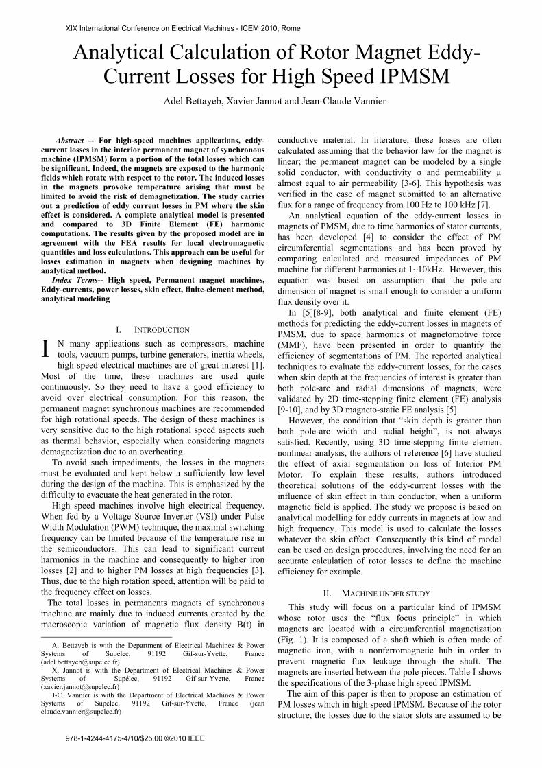
This study will focus on a particular kind of IPMSM whose rotor uses the “flux focus principle” in which magnets are located with a circumferential magnetization (Fig. 1). It is composed of a shaft which is often made of magnetic iron, with a nonferromagnetic hub in order to prevent magnetic flux leakage through the shaft. The magnets are inserted between the pole pieces. Table I shows the specifications of the 3-phase high speed IPMSM.
The aim of this paper is then to propose an estimation of PM losses which in high speed IPMSM. Because of the rotor structure, the losses due to the stator slots are assumed to be
Analytical Calculation of Rotor Magnet Eddy- Current Losses for High Speed IPMSM
Adel Bettayeb, Xavier Jannot and Jean-Claude Vannier
I
XIX International Conference on Electrical Machines - ICEM 2010, Rome
978-1-4244-4175-4/10/$25.00 ©2010 IEEE
negligible compared to those generated by time-harmonic currents which are mainly considered in the paper.
III. ANALYTICAL MODELS FOR FIELD AND LOSS
CALCULATIONS
A. Magnet’s magnetic flux density computation: Ampere’s law + Gauss’ law
The magnetic flux density in the magnets is computed as the sum of the field generated by d-axis stator current and the field generated by q-axis stator current [10].
The magnetic material is supposed to be unsaturated and has linear behavior. This assumption is quite always satisfied in high speed machines to avoid excessive iron losses [11].
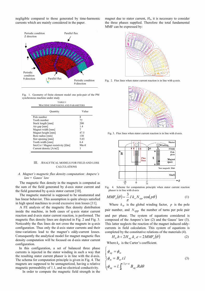
A FE analysis of the magnetic flux density distribution inside the machine, in both cases of q-axis stator current reaction and d-axis stator current reaction, is performed. The magnetic flux density lines are depicted in Fig. 2 and Fig. 3. Noticeably the flux lines do not cross the magnets in q-axis configuration. Thus only the d-axis stator currents and their time-variations lead to the magnet’s eddy-current losses. Consequently the analytical model for magnet magnetic flux density computation will be focused on d-axis stator current configuration.
In this configuration, a set of balanced three phase currents is injected in the stator winding in such a way that the resulting stator current phasor is in line with the d-axis. The schema for computation principle is given in Fig. 4. The magnets are supposed to be unmagnetized, having a relative magnetic permeability of 1.1, and no electrical conductivity.
In order to compute the magnetic field strength in the
magnet due to stator current, H0, it is necessary to consider the three phases supplied. Therefore the total fundamental MMF can be expressed by:
Fig. 2. Flux lines when stator current reaction is in line with q-axis.
Fig. 3. Flux lines when stator current reaction is in line with d-axis.
Fig. 4. Scheme for computation principle when stator current reaction phasor is in line with d-axis
pNkIMMF sppwd cos3
(1)
Where wk is the global winding factor, p is the pole
pair number, and sppN the number of turns per pole pair
and per phase. The system of equations considered is composed of the Ampere’s law (2) and the Gauss’ law (3). This latter neglects the reaction of the magnet induced eddy-currents in field calculation. This system of equations is completed by the constitutive relations of the materials (4). dcag MMFekHhH 2..2.0 (2)
Where ck is the Carter’s coefficient.
p
agag
mm
mag
RdBl
ltB2
0..
.. (3)
Fig. 1. Geometry of finite element model one pole-pair of the PM synchronous machine under study
TABLE I MACHINE DIMENSIONS AND PARAMETERS
Quantity Value
Pole number 8 Tooth number 72 Stack length [mm] 200 Air gap [mm] 1.4 Magnet width [mm] 7 Magnet height [mm] 47.5 Bore radius [mm] 130 Slot opening [mm] 5.03 Tooth width [mm] 6.4 Sm2Co17 Magnet resistivity [Ωm] 90e-8 Current density [A/m2] 1
Periodic condition θ direction
Periodic condition Z direction
Parallel flux
Parallel flux
Periodic condition θ direction
With: 2
1 h
R .
agag
m
HB
HB
.
.
0
0
(4)
A combination of (2), (3), and (4) allows writing the equation driving the magnetic field in the magnets:
Rhptek
INkRH
c
dsppw
.......4
...120 (5)
B. Eddy-current loss estimations
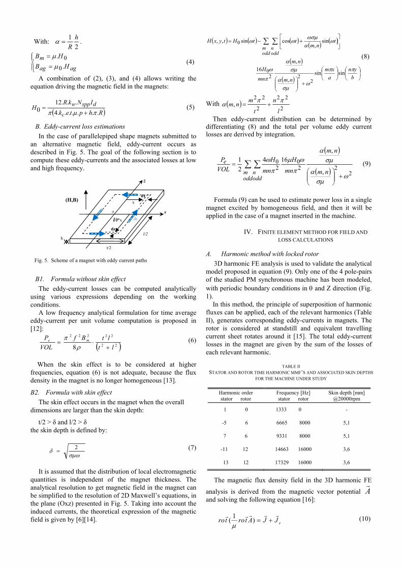
In the case of parallelepiped shape magnets submitted to an alternative magnetic field, eddy-current occurs as described in Fig. 5. The goal of the following section is to compute these eddy-currents and the associated losses at low and high frequency.
Fig. 5. Scheme of a magnet with eddy current paths
B1. Formula without skin effect
The eddy-current losses can be computed analytically using various expressions depending on the working conditions.
A low frequency analytical formulation for time average eddy-current per unit volume computation is proposed in [12]:
22
22222
8 lt
ltBf
VOL
P me
(6)
When the skin effect is to be considered at higher frequencies, equation (6) is not adequate, because the flux density in the magnet is no longer homogeneous [13].
B2. Formula with skin effect
The skin effect occurs in the magnet when the overall dimensions are larger than the skin depth:
t/2 > δ and l/2 > δ the skin depth is defined by:
2 (7)
It is assumed that the distribution of local electromagnetic
quantities is independent of the magnet thickness. The analytical resolution to get magnetic field in the magnet can be simplified to the resolution of 2D Maxwell’s equations, in the plane (Oxz) presented in Fig. 5. Taking into account the induced currents, the theoretical expression of the magnetic field is given by [6][14].
b
yn
a
xm
nm
nm
mn
H
tnm
ttHtyxH
oddm
oddn
sinsin,
,16
sin,
cossin,,
222
0
0
(8)
With 2
22
2
22,
l
n
t
mnm
Then eddy-current distribution can be determined by differentiating (8) and the total per volume eddy current losses are derived by integration.
oddm
oddn
e
nm
nm
mn
H
mn
H
VOL
P
222
020
,
,164
2
1
(9)
Formula (9) can be used to estimate power loss in a single
magnet excited by homogeneous field, and then it will be applied in the case of a magnet inserted in the machine.
IV. FINITE ELEMENT METHOD FOR FIELD AND
LOSS CALCULATIONS
A. Harmonic method with locked rotor
3D harmonic FE analysis is used to validate the analytical model proposed in equation (9). Only one of the 4 pole-pairs of the studied PM synchronous machine has been modeled, with periodic boundary conditions in and Z direction (Fig. 1). In this method, the principle of superposition of harmonic fluxes can be applied, each of the relevant harmonics (Table II), generates corresponding eddy-currents in magnets. The rotor is considered at standstill and equivalent travelling current sheet rotates around it [15]. The total eddy-current losses in the magnet are given by the sum of the losses of each relevant harmonic.
The magnetic flux density field in the 3D harmonic FE
analysis is derived from the magnetic vector potential A
and solving the following equation [16]:
eJJAtrotro
)1
(
(10)
t/2
l/2
x
l/t*x
h
dx
dz
(H,B)
x o
Je
z
TABLE II
STATOR AND ROTOR TIME HARMONIC MMF’S AND ASSOCIATED SKIN DEPTHS FOR THE MACHINE UNDER STUDY
Harmonic order stator rotor
Frequency [Hz] stator rotor
Skin depth [mm] @20000rpm
1 0 1333 0 -
-5 6 6665 8000 5,1
7 6 9331 8000 5,1
-11 12 14663 16000 3,6
13 12 17329 16000 3,6
Where J
is source current density, eJ
is the eddy-
current and µ is the permeability. The current density in the magnet is given by Faraday-
Maxwell’s equation solved with A
and V (V is electric scalar potential) and the Ohm’s law:
)( Vdgrat
AJ e
(11)
With σ is the conductivity of the magnet.
B. Eddy-current losses computation
The losses are evaluated in every element volume of permanent magnet as following:
n
iiiiie VJJP
1
).*(2
1 (12)
With n is number of element, Vi element volume of each
element in the magnet, J et Ji* are current density and conjugate current density in the magnet.
V. COMPARISONS BETWEEN ANALYTICAL AND FE RESULTS
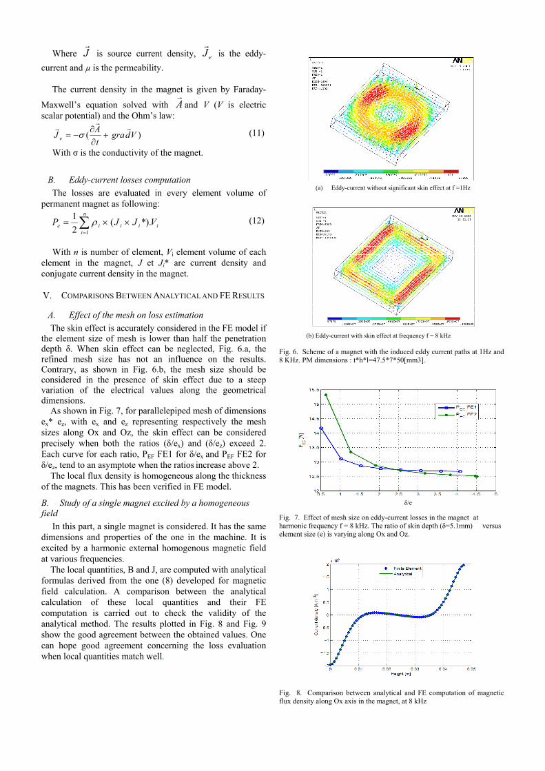
A. Effect of the mesh on loss estimation
The skin effect is accurately considered in the FE model if the element size of mesh is lower than half the penetration depth δ. When skin effect can be neglected, Fig. 6.a, the refined mesh size has not an influence on the results. Contrary, as shown in Fig. 6.b, the mesh size should be considered in the presence of skin effect due to a steep variation of the electrical values along the geometrical dimensions. As shown in Fig. 7, for parallelepiped mesh of dimensions ex* ez, with ex and ez representing respectively the mesh sizes along Ox and Oz, the skin effect can be considered precisely when both the ratios (δ/ex) and (δ/ez) exceed 2. Each curve for each ratio, PEF FE1 for δ/ex and PEF FE2 for δ/ez, tend to an asymptote when the ratios increase above 2. The local flux density is homogeneous along the thickness of the magnets. This has been verified in FE model.
B. Study of a single magnet excited by a homogeneous field
In this part, a single magnet is considered. It has the same dimensions and properties of the one in the machine. It is excited by a harmonic external homogenous magnetic field at various frequencies.
The local quantities, B and J, are computed with analytical formulas derived from the one (8) developed for magnetic field calculation. A comparison between the analytical calculation of these local quantities and their FE computation is carried out to check the validity of the analytical method. The results plotted in Fig. 8 and Fig. 9 show the good agreement between the obtained values. One can hope good agreement concerning the loss evaluation when local quantities match well.
(a) Eddy-current without significant skin effect at f =1Hz
(b) Eddy-current with skin effect at frequency f = 8 kHz Fig. 6. Scheme of a magnet with the induced eddy current paths at 1Hz and 8 KHz. PM dimensions : t*h*l=47.5*7*50[mm3].
Fig. 7. Effect of mesh size on eddy-current losses in the magnet at harmonic frequency f = 8 kHz. The ratio of skin depth (δ=5.1mm) versus element size (e) is varying along Ox and Oz.
Fig. 8. Comparison between analytical and FE computation of magnetic flux density along Ox axis in the magnet, at 8 kHz
δ/e
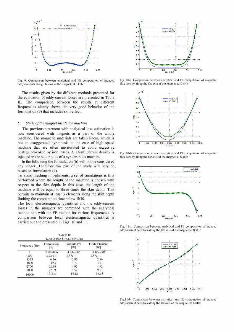
Fig. 9. Comparison between analytical and FE computation of induced eddy-currents along Ox axis in the magnet, at 8 kHz
The results given by the different methods presented for
the evaluation of eddy-current losses are presented in Table III. The comparison between the results at different frequencies clearly shows the very good behavior of the formulation (9) that includes skin effect.
C. Study of the magnet inside the machine
The previous statement with analytical loss estimation is now considered with magnets as a part of the whole machine. The magnetic materials are taken linear, which is not an exaggerated hypothesis in the case of high speed machine that are often unsaturated to avoid excessive heating provoked by iron losses. A 1A/m² current density is injected in the stator slots of a synchronous machine. In the following the formulation (6) will not be considered any longer. Therefore this part of the study will only be based on formulation (9). To avoid meshing impediments, a set of simulations is first performed where the length of the machine is chosen with respect to the skin depth. In this case, the length of the machine will be equal to three times the skin depth. This permits to maintain at least 3 elements along the skin depth limiting the computation time below 1h30. The local electromagnetic quantities and the eddy-current losses in the magnets are computed with the analytical method and with the FE method for various frequencies. A comparison between local electromagnetic quantities is carried out and presented in Figs. 10 and 11.
Fig. 10-a. Comparison between analytical and FE computation of magnetic flux density along the Ox axis of the magnet, at 8 kHz
Fig. 10-b. Comparison between analytical and FE computation of magnetic flux density along the Oz axis of the magnet, at 8 kHz
Fig. 11-a. Comparison between analytical and FE computation of induced eddy-current densities along the Ox axis of the magnet, at 8 kHz
Fig.11-b. Comparison between analytical and FE computation of induced eddy-current densities along the Oz axis of the magnet, at 8 kHz
TABLE III LOSSES IN A SINGLE MAGNET
Frequency [Hz] Formula (6)
[W] Formula (9)
[W] Finite Element
[W]
1 3.58e-006 4.03e-006 4.03e-006 300 3.22 e-1 3.37e-1 3.37e-1
1333 6.36 2.96 2.96 1800 11.59 3.77 3.77 2700 26.08 4.93 4.93 8000 228.9 9.52 9.53
16000 915.8 14.12 14.15

It can be observed a good agreement between analytical and 3D-FE-computed magnetic flux densities and induced currents along two cross line in the magnets. The skin effect is thus well taken into account. The losses are summarized in Table IV. The presented results show that the analytical estimation of eddy-current losses in the magnets are about 25% less than those estimated with FE.
The reference machine, defined in Table I, has a larger stack length. Therefore the system dimension in FE analysis is greater and leads to more important computation time, about 48h. The losses in the magnets are computed for various frequencies listed in Table V.
The comparison between analytical and FE results shows some deviation in case of variable stack length with frequency or in the case of the reference machine. Several reasons can explain a part of this deviation. First the contribution of q-axis current in eddy-current losses contribution is neglected in the analytical approach. However this contribution can explain why the absolute deviation increases with the frequency, the losses due to q-axis current also increase with frequency. Second the magnetic field computed with (5) can be imprecise due to simplifying hypothesis needed to set it up. Finally the hypothesis of field homogeneity across the magnet thickness is not fully satisfied in the machine, there are some side effects.
VI. CONCLUSION
In this paper, two ways of computing eddy-current losses in the IPMSM have been proposed. A complete analytical approach is described and compared to a numerical approach involving 3D-FE harmonic computations with the “locked rotor” test. The results show an acceptable deviation between both approaches in the case where skin effect appears. This phenomenon must be well addressed by both the analytical and 3D-FE method. It particularly concerns the mesh of 3D-FEM and the harmonic number in the analytical model.
An advantage of the analytical method is precisely to account for that skin effect and to estimate the eddy-current losses with a sufficient precision for a design stage. Moreover its very low computation time, less than one second, makes this approach very suitable for an iterative optimal design procedure. However, the field computation presents some deviations because of the simplified geometry and the neglect of the magnet eddy-current. Furthermore, the variation of the magnetic flux density in the q-axis is not considered for loss calculation.
On the other hand the 3D-FE harmonic approach based
on “locked rotor” method is more precise and can be involved in the detailed analysis of existing structures. In addition to, there is no need of large amount of CPU time or in storage space.
VII. REFERENCES [1] N. Bianchi, S. Bolognani, and F. Luise, “Potentials and Limits of
High-Speed PM Motors,” IEEE Trans. Industry Applications, vol. 40, no. 6, pp. 1570–1578, Nov./Dec. 2004.
[2] Yamazaki, K., Seto, Y. ,” Iron loss analysis of interior permanent-magnet synchronous motors-variation of main loss factors due to driving condition”, IEEE Transactions on Industry Applications, v 42, n 4, p 1045-52, July-Aug. 2006
[3] D. Ishak, Z. Q. Zhu, D. Howe’’, Eddy-Current Loss in the Rotor Magnets of Permanent-Magnet Brushless Machines Having a fractional Number of Slots Per Pole, IEEE Transactions on Magnetics”, vol. 41, n° 9, September 2005, p. 2462-2469.
[4] H. Polinder and M.J. Hoeijmakers, “Eddy-current losses in the Permanent magnets of a PM machine”, EMD97, Sep. 1997, pp.138-142.
[5] J. D. Ede, K. Attalah, G.W. Jewell, J. B. Wang, D. Howe, ’’Effect of Axial Segmentation of Permanent Magnets on Rotor Loss in Modular Permanent –Magnet Brushless Machines”, IEEE Transactions on Industry Applications, vol. 43, n° 5, September 2007, p.1207-1213.
[6] Y. Katsumi, A. Atsushi, “Loss Investigation of Interior Permanent-Magnet Motors Considering Carrier Harmonics and Magnet Eddy Currents” IEEE Transactions on Industry Application, vol. 45, n° 4, April 2009, p.659-665.
[7] A. Benabou, S. Georges, S. Clenet, “Permanent magnet modeling for dynamic applications”, Journal of magnetism and magnetic material, Vol.320, N°6, p 830-835, 2008.
[8] K. Altallah et al, “Rotor loss in Permanent-magnet brushless AC machines”, IEEE Trans. on Industry Applications, vo. 36, no. 6, Nov. 2000, pp. 1612-1617
[9] H. Toda et al, “Rotor eddy-current loss in permanent magnet brushless machines”, IEEE Trans. on Magnetics, vo. 40, no. 4, July 2004, pp.2104-2106
[10] X. Jannot, J-C. Vannier, J. Saint-Michel, M. Gabsi, C. Marchand, D. Sadarnac, »An analytical model for ipm synchronous machine with circumferential magnetization design” ,in Proc. Electromotion 2009, Lille, 2009
[11] A. Binder, T. Schneider, “High-speed inverter-fed AC drives”, Source: 2007 International Aegean Conference on Electrical Machines and Power Electronics (ACEMP '07), p 748-55, 2008
[12] W. Huang, A. Bettayeb, R. Kaczmarek and J. C. Vannier, “Optimisation of magnet segmentation for reduction of eddy-current losses in Permanent Magnet Synchronous Machine”, IEEE Trans. on Energy conversion, vo. 25, no. 2, pp. June 2010, pp.381-387
[13] S. M. Abu Sharkh, M. R Harris, N. Taghizadeh Irenji, ”Calculation of rotor Eddy current loss in High-speed PM alternators”, electrical Machines and Drives, pp 170-174, Sep.1997
[14] R. L. Stoll, ’’The Analysis of Eddy Current”, Oxford University press, chap4, pp 35-44, 1974.
[15] J. C. Vannier, R. Kaczmarek, Z. Wang, A. Randria, “Rotor loss in PMSM by calculation, simulation and measurements, mutual verification of methods”, Electrical Power Quality and Utilization, Journal Vol XII, N°2, 2006, P.113-116.
[16] Y. Kawase, T. Ota, and H. Furkunaga,”3-D Eddy current Analysis in permanent Magnet of interior Permanent Magnet Motors”, IEEE Transactions on Magnetics, vol. 36, n° 4, July 2000, p. 1863-1866.
Adel Bettayeb received the Ingénieur d’Etat Degree in electrical power engineering from the U.S.T.H.B University, Algiers, Algeria, in 2004, and the Master Degree from the University of Paul Sabatier, Toulouse, F.R.., in 2007. In December 2007 He is currently a PhD student in Ecole Supérieure d’Electricité SUPELEC (France). His research interests are on the rotor iron losses in synchronous machines Xavier Jannot is working towards the Ph.D. degree in Electrical Engineering with the Department of Electrical Power Systems in Supelec. His main research interests include multidisciplinary design of permanent magnet synchronous machine with their power electronic supply. Jean-Claude Vannier is Professor and head of “Department of Electrical Power Systems” in the Ecole Supérieure d’Electricité (Supélec) in France. His research interest is with energy conversion systems (motors, actuators, generators) and concerns the modeling, the design and the optimization of these equipments for specific applications.
TABLE IV LOSSES IN THE MAGNETS OF THE IPMSM: VARIABLE LENGTH WITH SKIN
EFFECT
Frequency [Hz] Formula (9)
[W] Finite Element
[W] Deviation [%]
8000 2.96e-10 3.83e-10 -22.71%
16000 4.18e-10 5.49e-10 -23.86%
TABLE V LOSSES IN THE MAGNETS OF THE IPMSM
Frequency [Hz] Formula (9)
[W] Finite Element
[W] Deviation [%]
8000 13.34 e-10 17.26 e-10 -22.67
16000 19.16e-10 24.29 e-10 -21.11