
Analysis of stress and strain in a rotating disk mounted ... · PDF fileAnalysis of stress and...
26
Analysis of stress and strain in a rotating disk mounted on a rigid shaft Nelli N. Alexandrova * Sergei Alexandrov † Paulo M. M. Vila Real ‡ Theoret. Appl. Mech., Vol.33, No.1, pp. 65–90, Belgrade 2006 Abstract The plane state of stress in an elastic-perfectly plastic isotropic rotating annular disk mounted on a rigid shaft is studied. The analysis of stresses, strains and displacements within the disk of constant thickness and density is based on the Mises yield crite- rion and its associated flow rule. It is observed that the plastic deformation is localized in the vicinity of the inner radius of the disk, and the disk of a sufficiently large outer radius never becomes fully plastic. The semi-analytical method of stress-strain analysis developed is illustrated by some numerical examples. Keywords: Rotating shaft-disk assembly, plane stress, strain dis- tribution, Mises yield criterion, semi-analytical solution. * Department of Civil Engineering, University of Aveiro, 3810-193 Aveiro, Portugal, e-mail:[email protected] † Institute for Problems in Mechanics, Russian Academy of Sciences, 101-1 Prospect Vernadskogo, 119526 Moscow, Russia, e-mail:sergei [email protected] ‡ Department of Civil Engineering, University of Aveiro, 3810-193 Aveiro, Portugal, e-mail:[email protected] 65
Transcript of Analysis of stress and strain in a rotating disk mounted ... · PDF fileAnalysis of stress and...

Analysis of stress and strain in arotating disk mounted on a rigid
shaft
Nelli N. Alexandrova ∗ Sergei Alexandrov †
Paulo M. M. Vila Real ‡
Theoret. Appl. Mech., Vol.33, No.1, pp. 65–90, Belgrade 2006
Abstract
The plane state of stress in an elastic-perfectly plastic isotropicrotating annular disk mounted on a rigid shaft is studied. Theanalysis of stresses, strains and displacements within the disk ofconstant thickness and density is based on the Mises yield crite-rion and its associated flow rule. It is observed that the plasticdeformation is localized in the vicinity of the inner radius of thedisk, and the disk of a sufficiently large outer radius never becomesfully plastic. The semi-analytical method of stress-strain analysisdeveloped is illustrated by some numerical examples.Keywords: Rotating shaft-disk assembly, plane stress, strain dis-tribution, Mises yield criterion, semi-analytical solution.
∗Department of Civil Engineering, University of Aveiro, 3810-193 Aveiro, Portugal,e-mail:[email protected]
†Institute for Problems in Mechanics, Russian Academy of Sciences, 101-1 ProspectVernadskogo, 119526 Moscow, Russia, e-mail:sergei [email protected]
‡Department of Civil Engineering, University of Aveiro, 3810-193 Aveiro, Portugal,e-mail:[email protected]
65

66 N.Alexandrova, S.Alexandrov, P.M.M.Vila Real
Notations:
A,B constants of integration;a, b inner and outer radii of the disk, respectively;c radius of elastic-plastic boundary;E modulus of elasticity;k shear yield stress;q ratio of inner to outer radius of the disk;u non-dimensional radial displacement;rθ plane polar coordinate system;sr, sθ non-dimensional deviator components of the stress tensor;β non-dimensional polar radius;γ non-dimensional radius of elastic-plastic boundary;ε total strain tensor;εr, εθ components of the total strain tensor;εe, εp elastic and plastic portions of the total strain tensor, respectively;εp
r, εpθ plastic components of the strain tensor in the plastic zone;
εer, ε
eθ elastic components of the strain tensor in the plastic zone;
εEr , εE
θ elastic components of the strain tensor in the elastic zone;ϕ function of r ;ϕe value of ϕ at Ω = Ωe and β = qϕq, ϕγ values of ϕ at β = q and β = γ , respectively;Φ1, Φ2, Φ3,Φ4, Φ5, Φ6 functions of ϕ ;ν Poisson’s ratio;ρ density of the material;σr, σθ non-dimensional components of the stress tensor;ξpr , ξ
pθ , ξ
er , ξ
eθ derivatives of εp
r, εpθ, ε
er, ε
eθ with respect to Ω ;
ω angular velocity;ωe angular velocity at the initial yielding;Ω, Ωe, Ωmax non-dimensional angular velocity parameters.

Analysis of stress and strain in a rotating disk... 67
1 Introduction
An annular disk mounted on a circular shaft rotating at high speed iswidely used in engineering applications. Numerous works have been pub-lished on analysis and design of such disks. In the case of elastic/plasticdisks, the study of stress and strain fields in rotating disks has begunwith models based on the Tresca yield criterion. A review of these worksis given in [1]. Other piece-wise linear yield criteria have been adoptedin [2, 3]. It has been mentioned in [1] that the analysis based on theTresca yield criterion is simpler than that based on the Mises yield cri-terion. However, in fact, it depends on loading conditions, and matchingdifferent regimes on the Tresca yield surface can require so cumbersomealgebraic transformations that the differential formulation following fromthe Mises constitutive equations looks much simpler [4]. On the otherhand, the development of computational models for plane stress elasto-plasticity meets some difficulties which do not exist in 3D and plane strainformulations [5]. Therefore, it seems that an appropriate approach to dealwith disk problems under plane stress conditions is to advance the analyt-ical treatment of the system of equations as much as possible and, then,to solve the resulting equation (or equations) numerically. In the case ofthe Mises yield criterion, such an approach has been developed [4, 6 – 8]for a class of problems for thin plates and disks. In particular, a hollowrotating disk with pressures prescribed at its inner and outer counter hasbeen studied in [4, 8]. In the present paper, this approach is extended torotating disks mounted on a rigid shaft. The presence of the shaft leadsto new qualitative features of the solutions which may be of importancein practical applications and may be helpful in gaining insight into thenature of possible numerical difficulties while solving more complex (ge-ometrically or physically) problems by means of finite element or othersimilar methods. Note that solutions for thin rotating disks based on theMises yield criterion are known in the literature, for example [9 - 14]. Inall of these studies, a deformation theory of plasticity has been adopted(stresses are related to plastic strains in the plastic zone). Different diskshapes, hardening laws and loading conditions have been investigated,though conceptually all these solutions are very similar to each other.
In contrast, the solution proposed in the present paper, as well as thesolutions given in [6, 8], use the theory of plastic flow (stresses are related

68 N.Alexandrova, S.Alexandrov, P.M.M.Vila Real
to plastic strain rates in the plastic zone). It makes a significant differencewith the solutions [9 – 14] in both the formulation of the problem andthe result obtained. In particular, because of the nature of deformationtheories of plasticity, it has been possible to prescribe a simple boundarycondition in terms of stress on the surface of a rigid inclusion (shaft)[11], whereas the present formulation requires a condition in terms ofvelocity (displacement). Moreover, in [12, 13] the fully plastic disk hasbeen considered, whereas the present solution shows that such a state ofthe disk is almost impossible and the limit angular velocity is determinedby another condition.
2 Statement of the problem and elastic load-
ing
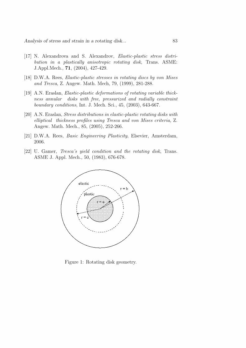
Consider a thin disk of material density ρ, shear yield stress k, Young’smodulus E, Poisson’s ratio ν, outer radius b, inner radius a mounted ona rigid shaft and rotating at an angular speed ω. The problem geometrysuggests the use of a plane polar coordinate system rθ with its origin atthe center of the shaft (Fig. 1). When the angular speed is high enough,the plastic zone develops in the region a ≤ r ≤ c where c is the radius ofelastic-plastic boundary. Obviously, the value of c depends on ω. In con-trast to the problem of a rotating hollow disk with prescribed pressures atr = a and r = b [4, 8], the problem under consideration is not staticallydetermined (even for perfectly plastic materials) since the only one stressboundary condition is given at r = b whereas the boundary conditionat r = a is given in terms of velocity (or displacement). This signifi-cantly complicates the solution. Because of the symmetry, the solution isindependent of θ.
Within the elastic zone c ≤ r ≤ b (or, in non-dimensional form,γ ≤ β ≤ 1) the Hooke’s law holds
(E/k) εr = σ−r νσ,θ (E/k) εθ = σ−θ νσr (1)
together with the compatibility equation
εr = d (βεθ)/dβ, (2)

Analysis of stress and strain in a rotating disk... 69
which is obtained from the well-known strain-displacement relations
εr = du/dβ, εθ = u/β (3)
Here σr and σθ are the non-dimensional (referred to k) radial andcircumferential components of the stress tensor, respectively; εr and εθ
are the radial and circumferential components of the strain tensor, re-spectively; β is the non-dimensional radius,β = r/b; and u is the non-dimensional (refereed to b) radial displacement; γ = c/b is the non-dimensional radius of the elastic-plastic boundary.
The only non-trivial equation of motion is
dσr/dβ + (σr − σθ)/β = −Ωβ, (4)
where Ω = ρω2b2/k is the non-dimensional angular velocity parameter.The outer radius of the disk is stress free. Therefore,
σr = 0 at β = 1 (5)
Both σr and σθ are to be continuous across the elastic-plastic bound-ary:
[σr] = 0, [σθ] = 0 at β = γ (6)
where square brackets denote the amount of jump in the quantity enclosedin the brackets. Eq. (5) in the case of elastic solution and Eqs. (5)-(6) in the case of elastic-plastic solution constitute the stress boundaryconditions which must be supplemented with the displacement boundaryconditions. Since the shaft is rigid,
u = 0 at β = q (7)
where q = a/b. The other condition, which is only applicable in the caseof elastic-plastic solution, is
[u] = 0 at β = γ (8)
Upon combining Eqs. (1) - (4), the radial displacement and stressdistributions in the elastic zone take the form

70 N.Alexandrova, S.Alexandrov, P.M.M.Vila Real
u =A (1 + ν)
β+ Bβ − 1− ν2
8
k
EΩβ3 (9)
σr = − A
β2+
B
1− ν− 3 + ν
8Ωβ2,
(10)
σθ =A
β2+
B
1− ν− 1 + 3ν
8Ωβ2
where A and B are constants to be found from the boundary conditions.For purely elastic loading occurring at small angular speeds, the bound-
ary conditions (5) and (7) result in
A = Ωq2 (1− ν)
8
[(1 + ν) q2 − (3 + ν)
(1− ν) q2 + (1 + ν)
],
(11)
B = (1− ν)
(3 + ν
8Ω + A
)
In the case of plastic loading, the representation for B in the form ofEq. (11)2 is still valid. Substituting it into Eqs. (9) - (10) leads to thedisplacement, strain and stress distributions in the elastic zone of theelastic/plastic disk
E
ku = A
((1− ν) β +
1 + ν
β
)+
1− ν
8βΩ
[3 + ν − β2 (1 + ν)
](12)
E
kεE
r = A
(1− ν − 1 + ν
β2
)+
1− ν
8Ω [3 + ν − 3β2 (1 + ν)] ,
E
kεE
θ = A
(1− ν +
1 + ν
β2
)+
1− ν
8Ω [3 + ν − β2 (1 + ν)]
(13)
σr = A
(1− 1
β2
)+
3 + ν
8Ω
(1− β2
),

Analysis of stress and strain in a rotating disk... 71
(14)
σθ = A
(1 +
1
β2
)+
3 + ν
8Ω
(1− 1 + 3ν
3 + νβ2
)
3 Plastic loading
Within the plastic zone q ≤ β ≤ γ, the stress equations consist of theplane stress Mises yield criterion
σ2r + σ2
θ − σrσθ = 3 (15)
and Eq. (4). Assuming that yielding starts at the inner radius of the disk,β = q, the value of the non-dimensional angular velocity parameter atwhich the plastic zone appears in the disk, Ωe, is obtained by substitutionof Eqs. (10)-(11) into Eq. (15)
Ωe =4√
3 [q2 (1− ν) + 1 + ν]
(1− q2) (ν2 − ν + 1)1/2 [q2 (1− ν) + 3 + ν](16)
To satisfy the yield criterion (15), the stresses can be represented inthe form
σr =√
3 cos ϕ− sin ϕ, σθ = −2 sin ϕ (17)
This substitution is very similar to the standard substitution intro-duced in [15]. The equation for ϕ (β, Ω) is determined upon substitutionof Eq. (17) into Eq. (4)
(√3 sin ϕ + cos ϕ
) ∂ϕ
∂β−
(√3 cos ϕ + sin ϕ
) 1
β− Ωβ = 0 (18)
Using Eq. (11) it is possible to find from Eq. (10) and Eq. (16) that
σr =√
3/√
ν2 − ν + 1, σθ =√
3ν/√
ν2 − ν + 1
at Ω = Ωe and β = q. Combining these values of the stresses and Eq.(17) determines ϕ at Ω = Ωe and β = q in the form

72 N.Alexandrova, S.Alexandrov, P.M.M.Vila Real
ϕe = − arcsin[√
3ν/(
2√
ν2 − ν + 1)]
(19)
It is interesting to mention that ϕe depends only on Poisson’s ratio.Since the coefficient of the derivative in Eq. (18) vanishes at ϕ = −π/6, itis a singular point of this equation. It is possible to show that its solutioncannot be extended beyond this point. Therefore, the admissible rangeof ϕ-value is
ϕe ≤ ϕ < −π/6 (20)
It is convenient to introduce the following functions of ϕ
Φ1 (ϕ) =√
3 sin ϕ + cos ϕ, Φ2 (ϕ) =√
3 sin ϕ− cos ϕ,
Φ3 (ϕ) =√
3 cos ϕ + sin ϕ, Φ4 (ϕ) =√
3 cos ϕ− sin ϕ,
Φ5 (ϕ) = ν√
3 sin ϕ− (2− ν) cos ϕ,
Φ6 (ϕ) = ν√
3 cos ϕ + (2− ν) sin ϕ
(21)
Substituting Eq. (14) and Eq. (17) into the boundary conditions (6)yields
γ2 =32
√Ω2 + 2ΩΦ6 (ϕγ) + Φ3 (ϕγ)
2 − 2Φ3 (ϕγ)− Ω (1 + ν)
Ω (1− ν)(22)
A =γ2
1 + γ2
Ω
8
[γ2 (1 + 3ν) + (3 + ν)
]− 2 sin ϕγ
(23)
where ϕγ is the value of ϕ at β = γ.The total strainε in the plastic zone is decomposed into its elastic and
plastic parts as
εr = εer + εp
r and εθ = εeθ + εp
θ (24)
The elastic part is obtained by substituting Eq. (17) into the Hooke’slaw (1)
(E/k) εer =
√3 cos ϕ− (1− 2ν) sin ϕ,

Analysis of stress and strain in a rotating disk... 73
(25)
(E/k) εeθ = −ν
√3 cos ϕ− (2− ν) sin ϕ
Differentiation of these equations with respect to time, which is denotedby the superimposed dot, gives the elastic portions of the strain ratetensor, εe
r and εeθ,
(E/k) εer = −ϕ
[√3 sin ϕ + (1− 2ν) cos ϕ
],
(26)
(E/k) εeθ = ϕ
[ν√
3 sin ϕ− (2− ν) cos ϕ]
The plastic portions of the strain rate tensor, εpr and εp
θ, obey theassociated flow rule. A consequence of this rule is
εpr/ε
pθ =sr/sθ (27)
where the components of the stress deviator tensor, sr and sθ, follow fromEq. (17) with the use of plane-stress assumption σz = 0
sr = 2 cos ϕ/√
3, sθ = −(√
3 sin ϕ + cos ϕ)/√
3 (28)
The incompressibility equation for plastic strains determines the strainrate εp
z. Substituting Eq. (28) into Eq. (27) yields
εpr = −2εp
θ cos ϕ/(√
3 sin ϕ + cos ϕ)
(29)
Eq. (2) and Eq. (24) are also applicable to strain rates. Combiningthese equations gives
∂ (εpθβ)/∂β = −∂ (εe
θβ)/∂β + εpr + εe
r (30)
Then, substituting Eq. (26) and Eq. (29) into Eq. (30) gives, withthe use of Eq. (21),
E
k
(β
∂εpθ
∂β+√
3εpθ
Φ3
Φ1
)= −
[(1 + ν) Φ2ϕ + β
(Φ5
∂ϕ
∂β+ Φ6ϕ
∂ϕ
∂β
)](31)

74 N.Alexandrova, S.Alexandrov, P.M.M.Vila Real
where the derivative ∂ϕ/∂β follows from Eq.(18) and will be denoted byD (β, ϕ)
D (β, ϕ) = ∂ϕ/∂β =[β2Ω + Φ3 (ϕ)
]/[βΦ1 (ϕ)] (32)
The time derivatives of functions involved in Eq. (31) may be writtenin the following form with Ω being a time-like variable
εpθ = (∂εp
θ/∂Ω) · (dΩ/dt) = ξpθ · (dΩ/dt) ,
ϕ = (∂ϕ/∂Ω) · (dΩ/dt) ,
∂ϕ/∂β = (∂2ϕ/∂Ω∂β) · (dΩ/dt)
(33)
Analogously, it is possible to introduce the quantities
εθ = (∂εθ/dΩ) · (dΩ/dt) = ξθ · (dΩ/dt) ,
εr = (∂εr/dΩ) · (dΩ/dt) = ξr · (dΩ/dt) ,
εpr = (∂εp
r/dΩ) · (dΩ/dt) = ξpr · (dΩ/dt) ,
εer = (∂εe
r/dΩ) · (dΩ/dt) = ξer · (dΩ/dt) ,
εeθ = (∂εe
θ/dΩ) · (dΩ/dt) = ξeθ · (dΩ/dt) ,
εEr =
(∂εE
r /dΩ) · (dΩ/dt) = ξE
r · (dΩ/dt) ,
εEθ =
(∂εE
θ /dΩ) · (dΩ/dt) = ξE
θ · (dΩ/dt)
(34)
Then, Eq. (31) becomes
βΦ1∂ξp
θ
∂β+√
3Φ3ξpθ =
k
E
∂ϕ
∂Ω
[2
Φ1
(Φ5 −
√3β2Ω
)− Φ3Φ6 − Φ1Φ2 (1 + ν)
]− Φ5β
2
(35)
The partial derivative ∂ϕ/∂Ω can be found as a function of β from the

Analysis of stress and strain in a rotating disk... 75
solution of the following equation obtained by differentiating Eq. (18)with respect to Ω
βΦ21
∂
∂β
(∂ϕ
∂Ω
)+
[Φ4
(Ωβ2 + Φ3
)+ Φ1Φ2
] ∂ϕ
∂Ω− β2Φ1 = 0 (36)
It is now necessary to formulate the boundary conditions to Eqs. (35)-(36). Denote the value of ϕ at β = q and β = γ by ϕq and ϕγ, respectively.Obviously, ϕq and ϕγ are functions of Ω. Since the surface β = q ismotionless, the following equation is valid
(∂ϕ/∂Ω)|β=q = dϕq/dΩ (37)
On the other hand, at the elastic-plastic boundary, β = γ,
∂ϕ
∂Ω=
dϕγ
dΩ− ∂ϕ
∂β
dγ
dΩ(38)
where ∂ϕ/∂Ω and ∂ϕ/∂β should be taken at β = γ. The latter derivativeis defined by Eq. (32). Therefore, Eq. (38) transforms to
∂ϕ
∂Ω
∣∣∣∣β=γ
=dϕγ
dΩ−D (γ, ϕγ)
dγ
dΩ(39)
Differentiating Eq. (22) with respect to Ω gives the following relationbetween dϕγ/dΩ and dγ/dΩ
dγ
dΩ=
4[γ2Φ2 (ϕγ) +
√3Φ3 (ϕγ)
]dϕγ/dΩ− [γ4 (1− ν) + 2γ2 (1 + ν)− 3− ν]
4γ [Ωγ2 (1− ν) + Ω (1 + ν) + 2Φ3 (ϕγ)](40)
Substituting Eq. (40) into Eq. (39) yields
∂ϕ
∂Ω
∣∣∣∣β=γ
=
[1− D (γ, ϕγ)
[γ2Φ2 (ϕγ) +
√3Φ3 (ϕγ)
]
γ [Ωγ2 (1− ν) + Ω (1 + ν) + 2Φ3 (ϕγ)]
]dϕγ
dΩ+
D (γ, ϕγ) [γ4 (1− ν) + 2γ2 (1 + ν)− 3− ν]
4γ [Ωγ2 (1− ν) + Ω (1 + ν) + 2Φ3 (ϕγ)]
(41)
Equation (36) should satisfy both Eq. (37) and Eq. (41).

76 N.Alexandrova, S.Alexandrov, P.M.M.Vila Real
The boundary condition (8) is equivalent to
[ξθ] = 0 at β = γ (42)
Since ξθ = ξEθ on the elastic side of elastic-plastic boundary and ξθ =
ξeθ + ξp
θ on its plastic side, Eq. (42) transforms to
ξpθ = ξE
θ − ξeθ at β = γ (43)
The value of ξeθ at β = γ is defined by Eq. (26)2, with the use of Eqs.
(33)-(34). Excluding here (∂ϕ/∂Ω)|β=γ by means of Eq. (39) gives
ξeθ =
k
E
(dϕγ
dΩ−D (γ, ϕγ)
dγ
dΩ
)Φ5 (ϕγ) (44)
where γ is defined by Eq. (22) and dγ/dΩ by Eq. (40). The value ofξEθ can be found by replacing A in Eq. (13)2 by means of Eq. (23) and
differentiating the resulting equation with respect to Ω
ξEθ = − k
4Eγ (1 + γ2)2
G1 (γ, ϕγ)
dϕγ
dΩ+ G2 (γ, ϕγ)
dγ
dΩ+
(45)
νγ(1− γ4
) [3 + ν + γ2 (1− ν)
]
where
G1 (γ, ϕγ) = 8γ [γ4 (1− ν) + 2γ2 + 1 + ν] cos ϕγ,
G2 (γ, ϕγ) = γ6Ω (3ν2 − 2ν − 1) + γ4Ω (3ν2 − 8ν − 3)−
−γ2 [Ω (7ν2 + 10ν − 1)− 16 (1− ν) sin ϕγ] +
(1 + ν) [Ω (3 + ν) + 16 sin ϕγ]
Here and in Eq. (44), γ should be excluded by means of Eq. (22) anddγ/dΩ by means of Eq. (40). Hence, substituting Eqs. (44)-(45) intoEq. (43) determines the value of ξp
θ at β = γ in terms of ϕγ and dϕγ/dΩ.This value will be denoted by ξp
θ |β=γ.

Analysis of stress and strain in a rotating disk... 77
The boundary condition (7) is equivalent to ξpθ = −ξe
θ at β = q. Thevalue of ξe
θ can be found from Eqs. (26)2, (33)-(34). Then, with the useof Eq. (37),
ξpθ = − k
E
dϕq
dΩΦ5 (ϕq) at β = q (46)
4 Numerical solution
Consider the generic line Ω = Ω(i) in the plastic zone (Fig.2) and assumethat ϕq and dϕq/dΩ at Ω = Ω(i−1) are known. The derivative dϕq/dΩwithin the interval Ω(i−1) ≤ Ω ≤ Ω(i) can be approximated as
dϕq
dΩ
∣∣∣∣i−1, i
≈ 1
2
(dϕq
dΩ
∣∣∣∣i−1
+dϕq
dΩ
∣∣∣∣i
)(47)
On the other hand,
dϕq
dΩ
∣∣∣∣i−1, i
≈ ϕq|i − ϕq|i−1
∆Ω(48)
where ∆Ω is the step in Ω, a small prescribed value. Combining Eqs.(47)-(48) gives
dϕq
dΩ
∣∣∣∣i
=2(ϕq|i − ϕq|i−1
)
∆Ω− dϕq
dΩ
∣∣∣∣i−1
(49)
Consider point e (Fig.2) where ϕγ = ϕq = ϕe, Ω = Ωe = Ω(0) andγ = q. The values of ϕe and Ωe are known due to Eq. (16) and Eq. (19).Combining Eq. (37) and Eq. (39) at this point it is possible to arrive at
dϕq
dΩ=
dϕγ
dΩ−D (q, ϕe)
dγ
dΩ(50)
The boundary condition (7) requires that ξEθ = 0 at point ewhere ξE
θ isdefined by Eq. (45). Combining this condition with Eq. (40) leads to thesystem of two equations with respect to dϕγ/dΩ and dγ/dΩ at Ω = Ωe =Ω(0), ϕ = ϕc, γ = q. Substituting these derivatives into Eq. (50) gives thevalue of dϕq/dΩ at Ω = Ω(0). Taking into account this value and following

78 N.Alexandrova, S.Alexandrov, P.M.M.Vila Real
the procedure outlined by Eq. (49), it is possible to find the derivativedϕq/dΩ at Ω = Ω(1), let’s denote it by (dϕq/dΩ)|1, in terms of ϕq|1. Itis now necessary to solve Eqs. (18), (35)-(36) numerically at Ω = Ω(1).The boundary conditions for Eq. (18) and Eq. (36) are ϕ = ϕq|1 and Eq.(37), respectively, where dϕq/dΩ = (dϕq/dΩ)|1. The solution to theseequations, with the use of Eqs. (22) and (41), determines, respectively,ϕγ|1 and (dϕγ/dΩ)|1. Therefore, ξp
θ |β=γ at Ω = Ω(1) is found in terms
of ϕq|1. The value of ξpθ |β=γ may serve as a boundary condition to Eq.
(35). However, the solution to Eq. (35) should also satisfy Eq. (46)which ultimately defines ∆Ω, and consequently ϕq|1. Since the derivative(dϕq/dΩ)|1 is now known, the procedure of finding distributions of ϕ, ξp
θ
and other functions along β at Ω = Ω(2) can be repeated for Ω = Ω(2)
and, then, for all other values Ω = Ω(i) at i > 2 as long as ϕq satisfies Eq.(20).
The derivative of radial displacement with respect to Ω is determinedby
∂u/∂Ω = β (ξpθ + ξe
θ) (51)
The distribution of the radial displacement is obtained by numericalintegration in Eq. (51) after the distribution of ξp
θ and ξeθ has been found
in the entire interval of Ω. The boundary condition to (51) follows from(12) at β = γ.
5 Numerical examples and conclusions
The theory presented is illustrated by some numerical examples. Thefollowing material properties have been used in all calculations: ν = 0.3,E = 200× 103MPa, and k = 127MPa.
Figs 3 through 5 show, respectively, the variation of ϕq, its derivativedϕq/dΩ, and the ratio γ/q, with the non-dimensional angular velocityparameter at different values of q. It is seen that the difference betweenthe maximum possible angular velocity parameter corresponding to Ωmax
and the angular velocity parameter corresponding to Ωe is very small.Here Ωmax can be considered as the non-dimensional limit angular velocityand is the value of Ω at ϕq = −π/6. The larger the shaft radius, the lowerangular velocity is required to reach max. It is also seen that the gradient

Analysis of stress and strain in a rotating disk... 79
of dϕq/dΩ is extremely high in the vicinity of Ωmax. It may lead todifficulties in numerical solutions for more complicated geometries wherethe analytical treatment of the problem is impossible. Fig. 5 showsthat the maximum possible thickness of the plastic zone is very smallas compared to the shaft radius. This result is very different from thatobtained by means of a deformation theory of plasticity [11-13].
The variation of ξpθ with Ω/Ωe at different β is illustrated in Fig. 6. It
is interesting to mention here that the function ξpθ (Ω) at specific values
of β reaches a minimum near Ω = Ωmax and, then, when Ω → Ωmax, itsgradient is very high.
The radial and circumferential stress distributions along the radiusat different values of the non-dimensional angular velocity parameter areshown in Figs 7 and 8, respectively. In the plastic zone, σr and σθ arealmost linear functions of β and the gradient of σθ is very high. Toshow better this qualitative effect of σθ distributions, the variation of σθ
with the radius at different values of the non-dimensional angular velocityparameter is illustrated in Fig.9 by using another scale. The increase inangular velocity leads to substantial rise in the circumferential stress inthe plastic region but does not produce such an effect with regard to theradial stress. While σθ reaches substantially high values in the plasticregion, σr accordingly adjusts itself so that the stress state remains onthe yield locus. Such variation of σθ with the radius is quite differentfrom that found by means of a deformation theory of plasticity [11-13].Even though variable thickness disks of strain-hardening material havebeen considered in these works, the disk of a constant thickness with nostrain hardening is obtained as a special case.
The variation of the total radial and circumferential strains with thenon-dimensional radius at different values of the non-dimensional angularvelocity parameter is shown in Figs 10 and 11, respectively, and theirplastic portions in Figs 12 and 13, respectively. The total circumferentialstrain is positive (Fig. 11) and slightly depends on Ω. However, itsplastic portion is negative everywhere in the plastic zone (Fig. 13) andsignificantly depends on Ω. On the other hand, the solution predicts thatthe plastic portion of the radial strain is positive everywhere in the plasticzone (Fig. 12), and the total radial strain becomes negative only at theedge of the disk (Fig. 10). The gradient of the radial strain is very highin the plastic zone (theoretically infinite when ϕq = −π/6). This results

80 N.Alexandrova, S.Alexandrov, P.M.M.Vila Real
in a high gradient of the axial strain, εz, and to intensive thinning in anarrow zone near β = q. The same effect (but opposite in terms of thesign) has been found in [16] in the case of expansion of a hole in a plateunder plane stress conditions. The behavior of the radial displacement(Fig. 14) is similar to that of total circumferential strain (Fig. 11).
Effects similar to the aforementioned ones also occur in disks withhard inclusions subject to thermal loading [6]. In the case of anisotropicrotating disks these effects can be even more pronounced, though it de-pends on the orientation of the principal axes of anisotropy. An illustra-tive example of the influence of anisotropy on the size of the plastic zoneis given in [17]. Even though, the solution found is for perfectly plasticmaterial, it may be more practical than the solutions found in [9–14] forstrain hardening materials. First, the present solution is based on a moreadvanced theory of plasticity. Second, for materials with a yield plateauthe elastic perfectly/plastic model adopted is more appropriate at smallstrains than models with strain hardening used in [9–14]. Moreover, evenif hardening starts from the very beginning, it is believed that its influenceon the qualitative behaviour of the solution is not so significant (thoughthis question requires further investigations) and the assumption of planestress plays the most important role.
Of special interest is comparison of solutions based on Tresca andMises yield criteria. Under different conditions, such comparisons havebeen made in [4, 12, 18, 19, 20]. It has been mentioned that the differ-ence between the solutions depends on the boundary conditions chosen.The boundary conditions accepted in the present paper have also beenconsidered in [19, 20] where, however, a deformation theory of plasticityof strain-hardening material has been adopted (in [19, 20], disks of vari-able thickness have been considered but the disk of a constant thicknesswith no strain hardening is obtained as a special case). The comparisonmade in this paper does not show a significant difference between thesolutions based on Tresca and Mises yield criteria. On the other hand,none of these solutions shows the qualitative effects demonstrated in thepresent solution, for example, the existence of the maximum angular ve-locity beyond which no solution exists, whereas the existence of such avelocity (or another parameter in the case of non-rotating disks) has beendemonstrated in other thin disk problems solved with the use of the the-ory of plastic flow [16, 21]. Another important effect of the application of

Analysis of stress and strain in a rotating disk... 81
Tresca yield criterion is that no plastic solution exits for a rotating soliddisk [22]. In other words, it means that no plastic zone develops. On theother hand, under different sets of conditions the solution based on Trescacriterion predicts a greater spread of plasticity at similar angular veloci-ties, as compared with the solution based on Mises criterion [21]. Takinginto account a great variety of results on comparison of the two typesof solutions, it is important to find the exact solution for the problemunder consideration based on Tresca yield criterion and compare it withthe present solution. This will be the subject of further investigations.
Acknowledgment
N.Alexandrova gratefully acknowledges support of this work from thePortuguese Science and Technology Foundation, grant SFRH / BPD/6549/ 2001, and S.Alexandrov acknowledges support through grant NSH-4472.2006.1 (Russia).
References
[1] A.N. Eraslan, Elastoplastic deformations of rotating parabolic soliddisks using Tresca’s yield criterion, Europ. J. Mech. A. Solids, 22,(2003), 861-874.
[2] G. Ma, H. Hao and Y. Miyamoto, Limit angular velocity of rotatingdisc with unified yield criterion, Int. J. Mech. Sci., 43, (2001), 1137-1153.
[3] M. Ghorashi and M. Daneshpazhooh, Limit analysis of variablethickness circular plates, Comp. Struct., 79, (2001), 461-468.
[4] N. Alexandrova and S. Alexandrov, Elastic-plastic stress distributionin a rotating annular disk, Mech. Based Design Struct. Machines, 32,(2004), 1-15.
[5] M. Kleiber and P. Kowalczyk, Sensitivity analysis in plane stresselasto-plasticity and elasto-viscoplasticity, Comp. Meth. Appl. Mech.Engrg, 137, (1996), 395-409.

82 N.Alexandrova, S.Alexandrov, P.M.M.Vila Real
[6] S. Alexandrov and N. Chikanova, Elastic-plastic stress-strain stateof a plate with a pressed-in inclusion in thermal field, Mech. Solids,35(4), (2000), 125-132 [trans.from Russian].
[7] S. Alexandrov and N. Alexandrova, Thermal effects on the develop-ment of plastic zones in thin axisymmetric plates, J. Strain AnalysisEngng Design, 36, (2001),169-176.
[8] N. Alexandrova, S. Alexandrov and P.M.M. Vila Real, Displacementfield and strain distribution in a rotating annular disk, Mech. BasedDesign of Struct. Machines, 32, (2004), 441-457.
[9] L.H. You, S.Y. Long and J.J. Zhang, Perturbation solution of rotatingsolid disks with nonlinear strain-hardening, Mech. Res. Comm., 24,(1997), 649-658.
[10] L.H. You, Y.Y. Tang, J.J. Zhang and C.Y. Zheng, Numerical analysisof elastic-plastic rotating disks with arbitrary variable thickness anddensity, Int. J. Solids Struct., 37, (2000), 7809-7820.
[11] A.N. Eraslan and H. Argeso, Limit angular velocities of variablethickness rotating disks, Int. J. Solids Struct., 39, (2002), 3109-3130.
[12] A.N. Eraslan, Inelastic deformations of rotating variable thicknesssolid disks byTresca and von Mises criteria, Int. J. Comput. EngrgSci., 3, (2002), 89-101.
[13] A.N. Eraslan, Von Mises yield criterion and nonlinearity hardeningvariable thickness rotating annular disks with rigid inclusion, Mech.Res. Comm., 29, (2002), 339-350.
[14] A.N. Eraslan, Y. Orcan and U. Guven, Elastoplastic analysis of non-linearly hardening variable thickness annular disks under externalpressure, Mech. Res. Comm., 32, (2005), 306-315.
[15] A. Nadai, Theory of Flow and Fracture of Solids, MsGraw-Hill, Lon-don, 1950.
[16] R. Hill, Mathematical Theory of Plasticity, Oxford Univ. Press, Lon-don, 1950.
Analysis of stress and strain in a rotating disk... 83
[17] N. Alexandrova and S. Alexandrov, Elastic-plastic stress distri-bution in a plastically anisotropic rotating disk, Trans. ASME:J.Appl.Mech., 71, (2004), 427-429.
[18] D.W.A. Rees, Elastic-plastic stresses in rotating discs by von Misesand Tresca, Z. Angew. Math. Mech, 79, (1999), 281-288.
[19] A.N. Eraslan, Elastic-plastic deformations of rotating variable thick-ness annular disks with free, pressurized and radially constraintboundary conditions, Int. J. Mech. Sci., 45, (2003), 643-667.
[20] A.N. Eraslan, Stress distributions in elastic-plastic rotating disks withelliptical thickness profiles using Tresca and von Mises criteria, Z.Angew. Math. Mech., 85, (2005), 252-266.
[21] D.W.A. Rees, Basic Engineering Plasticity, Elsevier, Amsterdam,2006.
[22] U. Gamer, Tresca’s yield condition and the rotating disk, Trans.ASME J. Appl. Mech., 50, (1983), 676-678.
Figure 1: Rotating disk geometry.

84 N.Alexandrova, S.Alexandrov, P.M.M.Vila Real
Figure 2: Illustration to the numerical procedure
Figure 3: Variation of ϕq with Ω/Ωe at different values of q.

Analysis of stress and strain in a rotating disk... 85
Figure 4: Variation of dϕq/dΩ with Ω/Ωe at different values of q.
Figure 5: Variation of the ratio γ/q with Ω/Ωe at different values of q.

86 N.Alexandrova, S.Alexandrov, P.M.M.Vila Real
Figure 6: Variation of ξpθ with Ω/Ωe at different values of β.
Figure 7: Radial stress distribution at q = 0.6 and different values of Ω.

Analysis of stress and strain in a rotating disk... 87
Figure 8: Hoop stress distribution at q = 0.6 and different values of Ω.
Figure 9: Hoop stress distribution at q = 0.6 and different values of Ω(different scale as compared to Fig.8).

88 N.Alexandrova, S.Alexandrov, P.M.M.Vila Real
Figure 10: Full radial strain distribution at q = 0.6 and different valuesof Ω.
Figure 11: Full circumferential strain distribution at q = 0.6 and differentvalues of Ω.

Analysis of stress and strain in a rotating disk... 89
Figure 12: Plastic radial strain distribution at q = 0.6 and different valuesof Ω.
Figure 13: Plastic circumferential strain distribution at q = 0.6 and dif-ferent values of Ω.

90 N.Alexandrova, S.Alexandrov, P.M.M.Vila Real
Figure 14: Radial displacement distribution at q = 0.6 and differentvalues of Ω.
Submitted on September 2006.
Analiza napona i deformacije u obrtnom diskupostavljenom na kruto vratilo
UDK 539.74
Proucava se ravansko naponsko stanje u elasticno–idealno plasticnomizotropnom obrtnom disku sa centricnim otvorom. Analiza napona, de-formacija i pomeranja unutar diska konstantne debljine i gustine zasnivase Mises-ovom pridruzenom uslovu tecenja. Primecuje se da je plasticnadeformacija lokalizovana u blizini unutrasnjeg poluprecnika diska, takoda disk dovoljno velikog spoljnog poluprecnika nikada ne postaje pot-puno plastican. Poluanaliticka metoda naponsko-deformacione analize jerazvijena i ilustrovana nekim numerickim primerima.

![PowerPoint Presentation€¢ Hazelcast • memcached • OpenLink Virtuoso • Redis • XAP KV — solid-state drive or rotating disk [edit] • Aerospike • COB](https://static.fdocuments.in/doc/165x107/5b2c0a017f8b9a5c478bd75f/powerpoint-hazelcast-memcached-openlink-virtuoso-redis-xap-kv.jpg)


![ALMA reveals a rotating [CII] disk in a gas rich galaxy at z = 4.76](https://static.fdocuments.in/doc/165x107/56815f0f550346895dcdce25/alma-reveals-a-rotating-cii-disk-in-a-gas-rich-galaxy-at-z-476.jpg)


