Noncontact Free-Rotating Disk Triboelectric … Free-Rotating Disk Triboelectric Nanogenerator as a...
17
Noncontact Free-Rotating Disk Triboelectric Nanogenerator as a Sustainable Energy Harvester and Self-Powered Mechanical Sensor Long Lin, †,§ Sihong Wang, †,§ Simiao Niu, †,§ Chang Liu, † Yannan Xie, † and Zhong Lin Wang* ,†,‡ † School of Materials Science and Engineering, Georgia Institute of Technology, Atlanta, Georgia 30332-0245, United States ‡ Beijing Institute of Nanoenergy and Nanosystems, Chinese Academy of Sciences, Beijing 100083, China * S Supporting Information ABSTRACT: In this work, we introduced an innovative noncontact, free-rotating disk triboelectric nanogenerator (FRD-TENG) for sustainably scavenging the mechanical energy from rotary motions. Its working principle was clarified through numerical calculations of the relative-rotation-induced potential difference, which serves as the driving force for the electricity generation. The unique characteristic of the FRD-TENG enables its high output performance compared to its working at the contact mode, with an effective output power density of 1.22 W/m 2 for continuously driving 100 light-emitting diodes. Ultrahigh stability of the output and exceptional durability of the device structure were achieved, and the reliable output was utilized for fast/effective charging of a lithium ion battery. Based on the relationship between its output performance and the parameters of the mechanical stimuli, the FRD-TENG could be employed as a self-powered mechanical sensor, for simultaneously detecting the vertical displacement and rotation speed. The FRD-TENG has superior advantages over the existing disk triboelectric nanogenerator, and exhibits significant progress toward practical applications of nanogenerators for both energy harvesting and self-powered sensor networks. KEYWORDS: triboelectric nanogenerator, noncontact, rotational mechanical energy, self-powered system, high stability, active sensor ■ INTRODUCTION The worldwide energy crises and environmental pollution have drawn long-lasting attention to green energy and sustainable development. 1,2 Harvesting energy from the ambient environ- ment is a good choice to solve the energy-related problems without causing unexpected environmental issues. 3−6 Among multiple energy sources, mechanical energies are universally available, environmental friendly, and can be scavenged through various approaches based on the piezoelectric, 7−9 electro- static, 10,11 and electromagnetic effects. 12−14 The recently invented triboelectric nanogenerator (TENG) 15−18 has been proven to be an effective method for converting the mechanical agitations into electricity by the conjunction of contact electrification and electrostatic induction. 19 However, most of the existing configurations of TENGs are designed for harvesting energy from an oscillating linear motion that realizes periodic separations of triboelectically charged (tribo-charged) surfaces in contact 20 or sliding 21 modes, while a rotary mechanical energy is also widely available in our daily life (like wheels, turbines, bearings, etc). Although we have demonstrated the segmentally structured disk triboelectric nanogenerator (D-TENG) 22 on the basis of the in-plane charge separation mechanism for such applications, its output performance, especially the stability/durability, still needs further improvement for long-term working. The limitations of such D-TENG exist in the following two aspects: (1) both the rotational and stationary triboelectric layers require deposition of metal electrodes and connection with electrical leads, leading to inconvenient operation of the rotational part; (2) intimate contact is mandatory to achieve efficient electricity generation, which results in possible material abrasion, instability of output, and limited lifetime of the TENG. To resolve the above issues for the existing D-TENG, in this work we designed a novel type of disk TENG with both groups of patterned electrodes attached onto a stationary disk, together with a freestanding triboelectric layer on a rotational disk. With such a structure, there is no necessity for electrode deposition or electrical connection for the rotational part, which dramatically improves the operating facility of the energy harvester. Moreover, owing to the unique feature of this new electricity-generation mechanism, the noncontact free-rotating disk triboelectric nanogenerator (FRD-TENG) can be operated without friction after initial contact electrification, with little lost on performance but superior durability enhancement, because the surface triboelectric charges preserve on insulator surfaces for hours. 23 Under the noncontact condition, an open- circuit voltage (V OC ) of 220 V and a short-circuit current density (J SC ) up to 13 mA/m 2 were produced, with an effective output power density of 1.22 W/m 2 , which is enough for instantaneously and continuously driving 100 serially connected Received: December 7, 2013 Accepted: January 20, 2014 Published: January 27, 2014 Research Article www.acsami.org © 2014 American Chemical Society 3031 dx.doi.org/10.1021/am405637s | ACS Appl. Mater. Interfaces 2014, 6, 3031−3038
Transcript of Noncontact Free-Rotating Disk Triboelectric … Free-Rotating Disk Triboelectric Nanogenerator as a...

Noncontact Free-Rotating Disk Triboelectric Nanogenerator as aSustainable Energy Harvester and Self-Powered Mechanical SensorLong Lin,†,§ Sihong Wang,†,§ Simiao Niu,†,§ Chang Liu,† Yannan Xie,† and Zhong Lin Wang*,†,‡
†School of Materials Science and Engineering, Georgia Institute of Technology, Atlanta, Georgia 30332-0245, United States‡Beijing Institute of Nanoenergy and Nanosystems, Chinese Academy of Sciences, Beijing 100083, China
*S Supporting Information
ABSTRACT: In this work, we introduced an innovative noncontact,free-rotating disk triboelectric nanogenerator (FRD-TENG) forsustainably scavenging the mechanical energy from rotary motions. Itsworking principle was clarified through numerical calculations of therelative-rotation-induced potential difference, which serves as the drivingforce for the electricity generation. The unique characteristic of theFRD-TENG enables its high output performance compared to itsworking at the contact mode, with an effective output power density of1.22 W/m2 for continuously driving 100 light-emitting diodes. Ultrahighstability of the output and exceptional durability of the device structurewere achieved, and the reliable output was utilized for fast/effectivecharging of a lithium ion battery. Based on the relationship between itsoutput performance and the parameters of the mechanical stimuli, theFRD-TENG could be employed as a self-powered mechanical sensor, for simultaneously detecting the vertical displacement androtation speed. The FRD-TENG has superior advantages over the existing disk triboelectric nanogenerator, and exhibitssignificant progress toward practical applications of nanogenerators for both energy harvesting and self-powered sensor networks.
KEYWORDS: triboelectric nanogenerator, noncontact, rotational mechanical energy, self-powered system, high stability, active sensor
■ INTRODUCTION
The worldwide energy crises and environmental pollution havedrawn long-lasting attention to green energy and sustainabledevelopment.1,2 Harvesting energy from the ambient environ-ment is a good choice to solve the energy-related problemswithout causing unexpected environmental issues.3−6 Amongmultiple energy sources, mechanical energies are universallyavailable, environmental friendly, and can be scavenged throughvarious approaches based on the piezoelectric,7−9 electro-static,10,11 and electromagnetic effects.12−14 The recentlyinvented triboelectric nanogenerator (TENG)15−18 has beenproven to be an effective method for converting the mechanicalagitations into electricity by the conjunction of contactelectrification and electrostatic induction.19 However, most ofthe existing configurations of TENGs are designed forharvesting energy from an oscillating linear motion that realizesperiodic separations of triboelectically charged (tribo-charged)surfaces in contact20 or sliding21 modes, while a rotarymechanical energy is also widely available in our daily life(like wheels, turbines, bearings, etc). Although we havedemonstrated the segmentally structured disk triboelectricnanogenerator (D-TENG)22 on the basis of the in-plane chargeseparation mechanism for such applications, its outputperformance, especially the stability/durability, still needsfurther improvement for long-term working. The limitationsof such D-TENG exist in the following two aspects: (1) boththe rotational and stationary triboelectric layers require
deposition of metal electrodes and connection with electricalleads, leading to inconvenient operation of the rotational part;(2) intimate contact is mandatory to achieve efficient electricitygeneration, which results in possible material abrasion,instability of output, and limited lifetime of the TENG.To resolve the above issues for the existing D-TENG, in this
work we designed a novel type of disk TENG with both groupsof patterned electrodes attached onto a stationary disk, togetherwith a freestanding triboelectric layer on a rotational disk. Withsuch a structure, there is no necessity for electrode depositionor electrical connection for the rotational part, whichdramatically improves the operating facility of the energyharvester. Moreover, owing to the unique feature of this newelectricity-generation mechanism, the noncontact free-rotatingdisk triboelectric nanogenerator (FRD-TENG) can be operatedwithout friction after initial contact electrification, with littlelost on performance but superior durability enhancement,because the surface triboelectric charges preserve on insulatorsurfaces for hours.23 Under the noncontact condition, an open-circuit voltage (VOC) of 220 V and a short-circuit currentdensity (JSC) up to 13 mA/m2 were produced, with an effectiveoutput power density of 1.22 W/m2, which is enough forinstantaneously and continuously driving 100 serially connected
Received: December 7, 2013Accepted: January 20, 2014Published: January 27, 2014
Research Article
www.acsami.org
© 2014 American Chemical Society 3031 dx.doi.org/10.1021/am405637s | ACS Appl. Mater. Interfaces 2014, 6, 3031−3038
light-emitting diodes (LEDs). The high output power remainsstable upon continuous working for 500 000 cycles and iscapable of fully charging a lithium ion battery (LIB) within 1.5h, with an equivalent DC charging current of 7.5 μA. Finally,the FRD-TENG can be employed as a self-powered mechanicalsensor for simultaneously detecting the vertical separationdistance between the two disks and the rotation speed, throughreading the magnitude and the frequency of the measured JSC.This work presents an outstanding progress toward thepractical applications of nanogenerators in harvesting rotationalmechanical energy, and boosts the development of self-powered sensor networks,24−26 especially for application inthe braking systems of automobile industry.
■ RESULTS AND DISCUSSION
As schematically illustrated in Figure 1a, the basic structure ofthe FRD-TENG consists of two parts: the freestandingrotational part of tribo-charged layer and the stationary partof metal electrodes. The rotational part was fabricated from apiece of fluorinated ethylene propylene (FEP) thin film (∼50μm in thickness), which was tailored into a four-segmentstructure and attached onto an acrylic supporting substrate withsame shape. In this new structure, there is no need to deposit
electrode on the back surface of the FEP membrane, indicatingthat versatile energy harvesting is achievable with an arbitrarymoving object without processing (e.g., rotating tires). Thestationary part is composed of two separated aluminum foils(∼50 μm in thickness and 4 in. in diameter) withcomplementary four-segment shapes attached on a round-shape acrylic disk, which act as the two stationary electrodes.To increase the density of triboelectric charges throughenhanced electrification process, micropatterned structureswere introduced on the inner surface of both triboelectriclayers, respectively. On one side, the inductively coupledplasma (ICP) process was utilized to create nanorods on thesurface of the FEP film by reactive ion etching (RIE);27 on theother side, we employed the photolithography approach toselectively deposit aluminum patterns of microscale cubicstructure onto the flat aluminum foil. The typical scanningelectron microscopy (SEM) images of both structures aredisplayed in Figures 1b and 1c. The two triboelectric layerswere first brought into contact to produce triboelectric chargesthrough the transfer of electrons from the surface of aluminumto FEP. The surface charges on the dielectric FEP wouldremain almost unchanged for days, and then the device couldbe continuously working even when the two layers were not incontact. This is the initial step to have the two surfaces being
Figure 1. Device structure of the noncontact free-rotating disk triboelectric nanogenerator. (a) A schematic of the basic structure of the FRD-TENGcomposed of the freestanding FEP layer and the stationary aluminum layer. The bottom inset is the figure legend. (b) A 30°-tilted-view SEM imageof the nanorod structure created on the surface of the FEP thin film. (c) A top view SEM image of the cubic micropatterned structures on thealuminum foil.
Figure 2. Theoretical study on the working principle of the FRD-TENG. (a) Schematic illustrations showing the working principle of the FRD-TENG in a full cyclic motion of the rotational disk. (b) Numerical calculations on the induced potential differences between the two aluminumelectrodes at the four steps of motion in a full cycle. The right inset shows the color legend about the value of potential.
ACS Applied Materials & Interfaces Research Article
dx.doi.org/10.1021/am405637s | ACS Appl. Mater. Interfaces 2014, 6, 3031−30383032
electrostatically charged with opposite signs of charges,respectively. The length of time that the electrostatic chargesare preserved on the surfaces depends on the nature of thematerials and conditions in environment such as humidity. Thesurface triboelectric charges could even be regenerated bybringing the two surfaces back to contact after a long term ofnoncontact operation. In the experiment, the rotational partwas driven by a rotation motor with tunable rotation speed (r),and the stationary part was fixed on a three-dimensional stageto control the vertical distance (d) between the two paralleltriboelectric surfaces.The working principle of the FRD-TENG is schematically
depicted in Figure 2a. For simplicity purposes, all of theschematics in this figure are plotted in a two-dimensional cross-sectional view. The energy generation process of the FRD-TENG can be divided into two major steps: the initial contactelectrification step and the cyclic rotational electrostaticinduction step. At first, the FEP segments were brought intocontact with one layer of the aluminum foil, which is named asA1, with the other layer of the aluminum foil as A2. Due to thedifferent triboelectric polarities of the two surfaces, theelectrons will be injected from the aluminum foil to the FEPsurface, leaving net negative charges on the FEP surface, andnet positive charges on the aluminum foil.28−30 Then, the twolayers were brought apart, leaving a 0.5 mm thick air media inbetween. At this right moment, since the vertical separationdistance is relatively small compared to the horizontal distancebetween the mass centers of two adjacent aluminum segments,only few electrons will be driven to flow from A2 to A1 (step I).
As the freestanding segment of FEP is rotating from A1 to A2,the electrons will flow from A2 to A1 to screen the potentialdifference generated by the nonmobile negative charges on theFEP surface, producing the first half cycle of the energyconversion process (step II). When the FEP reaches theoverlapping position of A2, the majority of electrons will bedriven to A1, leaving most of the positive charges on A2 (stepIII). In the next step of motion, the segments of FEP will startto move toward the adjacent segment of A1. As a result, theelectrons will move back from A1 to A2, leading to an outputcurrent with the opposite direction (step IV), until the FEPsegments return to the original position, which is the secondhalf of the energy conversion process.To obtain a quantitative understanding about the working
mechanism of the FRD-TENG, numerical calculations on theinduced potential difference31,32 in different motion steps werecarried out using Comsol 4.2a, as displayed in Figure 2b. Thethree-dimensional illustrations corresponding to this full cycleof motion discussed above are plotted in Figure S1 in theSupporting Information. In the established model, the FEPlayer and aluminum layers with the same size and segmentalstructure were stacked in the vertical direction with an air gapof 0.5 mm, which is the same as the experimental conditions.Initially, the FEP thin film (with an assumed tribo-chargedensity of Q0 = 25 μC/m2) is fully over A1, and most of thepositive tribo-charges are assumed to distribute on Al as theminimum achievable charge reference state. As expected, thecalculation result shows no potential difference between thetwo electrodes (step I). In the following step, the negatively
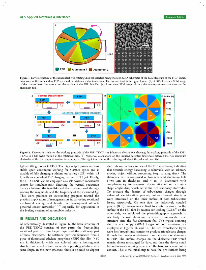
Figure 3. Electrical output characteristics of the FRD-TENG. (a1−a3) The measured VOC, QSC, and JSC of the FRD-TENG at contact mode,respectively. (b1−b3) The measured VOC, QSC, and JSC of the FRD-TENG at noncontact mode, respectively. The insets are the enlarged viewshowing the detailed shape of each output profile. (c) The measured output voltage and current across an external load with variable resistances. (d)The calculated effective power output of the FRD-TENG with variable resistances. (e) A snapshot from the video showing that the FRD-TENG isable to power up 100 serially connected LED instantaneously and continuously.
ACS Applied Materials & Interfaces Research Article
dx.doi.org/10.1021/am405637s | ACS Appl. Mater. Interfaces 2014, 6, 3031−30383033
charged FEP surface rotates to the middle position between thetwo electrodes, resulting in a relatively higher potentialdifference (step II). As the FEP segments move to theoverlapping position over A2 (step III), the calculated inducedpotential difference reaches its maximum value (∼4 kV), andthe increase of potential difference provides the driving forcefor the electrons flowing in the external load. Finally, the FEPlayer moves toward the adjacent A1 electrode through thesymmetric position with step II with equal potential difference(step IV), until the FEP layer returns to the original positionafter a full energy conversion cycle.The typical output characteristics of the FRD-TENG
operated at 500 rpm are presented in Figure 3b, and thesewere compared with the corresponding output performances atcontact-mode (Figure 3a). Figure 3a1−3 shows the open-circuit voltage (VOC), the transferred charge density (QSC), andthe short-circuit current density (JSC) of the TENG undercontact mode (d = 0), respectively. Under this condition it canbe found that VOC = 250 V, QSC =21 μC/m
2, and JSC =2.0 mA/m2. The corresponding measurement results of the noncontactmode (d = 0.5 mm) are shown in Figure 3b1−3. The outputperformances for the noncontact mode are only slightly lowerthan those for the contact mode, with VOC = 220 V, QSC = 20μC/m2, and JSC = 1.8 mA/m2. These results elucidate the FRD-TENG’s capability of effectively generating electricity withoutfurther friction, indicating that a tight contact during the energyconversion process is no longer necessary. Specifically, it can befound that the output profiles of both the VOC and the QSC aretriangular waveform, while the JSC yields square waveform
(insets of Figure 3b), which reflects the time-differentiationrelationship between the transferred charges and the current.To gain a comprehensive view of the effective output power onthe external load, we conducted the measurement of the outputvoltage and current with variable load resistances, as shown inFigure 3c. Generally, the output voltage increases with theloading resistance while the output current exhibits an oppositetrend. Both curves have a quasi-linear region between 0.1 and100 MΩ, where their variations with the loading resistancebecome significant. The output power with different resistancescould be calculated by simply multiplying the as-measured dataof the output current and voltage, as summarized in Figure 3d.Based on this result, it can be found that the maximum outputpower density of the FRD-TENG is 1.22 W/m2, at a loadresistance of ∼2 MΩ. The high output power of the FRD-TENG can be utilized for instantaneously and continuouslydriving 100 LEDs in serial connection, as shown in Figure 3eand Supporting Information Video S1, implying its applicationsas a self-lighting disk for security monitoring, wind detection, oramusement purposes.Owing to its unique working principle and the noncontact
operation capability, the FRD-TENG has significant advantagescompared to the previously demonstrated D-TENG, in thedurability of device structure, the stability of its electrical output(especially at very high rotation speed), and the energyconversion efficiency. To demonstrate this superiority of theFRD-TENG, the stability tests were carried out on a devicewith an eight-segment structure (inset of Figure 4a), at arotation speed of 3000 rpm. At first, all three output parameters
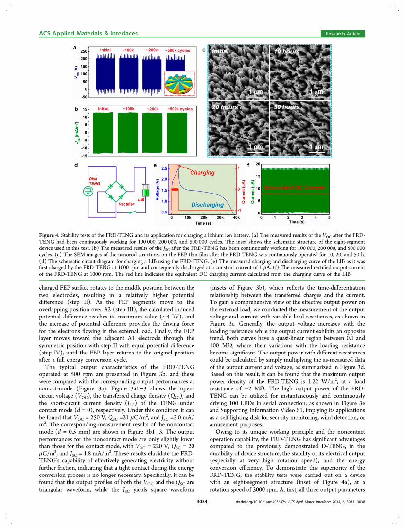
Figure 4. Stability tests of the FRD-TENG and its application for charging a lithium ion battery. (a) The measured results of the VOC after the FRD-TENG had been continuously working for 100 000, 200 000, and 500 000 cycles. The inset shows the schematic structure of the eight-segmentdevice used in this test. (b) The measured results of the JSC after the FRD-TENG has been continuously working for 100 000, 200 000, and 500 000cycles. (c) The SEM images of the nanorod structures on the FEP thin film after the FRD-TENG was continuously operated for 10, 20, and 50 h.(d) The schematic circuit diagram for charging a LIB using the FRD-TENG. (e) The measured charging and discharging curve of the LIB as it wasfirst charged by the FRD-TENG at 1000 rpm and consequently discharged at a constant current of 1 μA. (f) The measured rectified output currentof the FRD-TENG at 1000 rpm. The red line indicates the equivalent DC charging current calculated from the charging curve of the LIB.
ACS Applied Materials & Interfaces Research Article
dx.doi.org/10.1021/am405637s | ACS Appl. Mater. Interfaces 2014, 6, 3031−30383034
of the FRD-TENG were measured before and after a 500 000-cycle continuous operation, and it is obvious that they all(Figure 4a, b and Figure S2) display little drops after 500 000cycles of operation. Such supreme stability results from theelimination of the surface abrasion during the noncontactoperation. The SEM images of the FEP microstructures weretaken after 10, 20, and 50 h of operation in the FRD-TENG, asshown in Figure 4c. It can be observed that the polymernanorods were rarely affected by the huge numbers ofelectricity generation cycles, indicating the superhigh durabilityof the device structure at the microscale.For most of the energy harvesting techniques, it is needed to
store the power scavenged from the environment in an energystorage unit, like a capacitor or a LIB. Because of the uniquestability of the FRD-TENG, it can effectively charge ahomemade LIB (LiFePO4 as the cathode and TiO2 as theanode) after rectification, which takes much longer chargingtime than a capacitor. The charging circuit diagram is shown inFigure 4d. From the measured charging curve in Figure 4e, itcan be found that the LIB was successfully charged from 0.7 V(indicating empty capacity for this battery system) to over 2.5V (indicating full capacity) in less than 1.5 h, by the FRD-TENG operated under the rotation speed of 1000 rpm. Thefully charged LIB can provide a constant current of 1 μA for
around 10 h. We continue to calculate the equivalent constantDC current (Iequ) indicating that the output current of theTENG has equal effect to a certain constant current whencharging an energy storage unit. The Iequ could be calculatedfrom the charging curve by
=II t
tequdisch disch
ch (1)
Here, Idisch is the constant discharging current, tdisch is thedischarging time, and tch is the charging time. Based on eq 1, itcan be calculated that Iequ = 7.5 μA for this measurement, whichis ∼41% of the peak value of the rectified current (Figure 4f).The charging curve of the LIB at a relative lower speed (500rpm) was also measured, as plotted in Figure S3, and it wascalculated that Iequ = 3.0 μA (33% of the peak rectified current),which is lower due to decreasing number of charge transfercycles in certain time.In the noncontact operation mode, the vertical distance (d)
between the freestanding FEP layer and the fixed aluminumlayers is a critical parameter on the output performance. Toelucidate its impact, the output performances of the FRD-TENG under a series of distances increasing from 0 to 5 mmwere measured at a constant rotation speed of 500 rpm. As
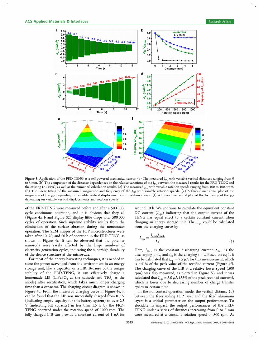
Figure 5. Application of the FRD-TENG as a self-powered mechanical sensor. (a) The measured JSC with variable vertical distances ranging from 0to 5 mm. (b) The comparison of the distance dependences on the relative variations of the JSC between the measured results for the FRD-TENG andthe existing D-TENG, as well as the numerical calculation results. (c) The measured JSC with variable rotation speeds ranging from 100 to 1000 rpm.(d) The linear fitting of the measured magnitude and frequency of the JSC with variable rotation speeds. (e) A three-dimensional plot of themagnitude of the JSC depending on variable vertical displacements and rotation speeds. (f) A three-dimensional plot of the frequency of the JSCdepending on variable vertical displacements and rotation speeds.
ACS Applied Materials & Interfaces Research Article
dx.doi.org/10.1021/am405637s | ACS Appl. Mater. Interfaces 2014, 6, 3031−30383035
displayed in Figure 5a, the as-measured JSC shows a decreasingtrend from 2.0 to 0.5 mA/m2, since the electrostatic inductionof the negatively charged FEP layer becomes lower. We alsoemployed numerical calculations to gain a theoretical under-standing about the impact of the separation distance on theoutput of the FRD-TENG (Figure S4). As d increases from 0 to5 mm, the induced potential difference exhibits an obviousdescending trend, and the impact on the QSC and the JSC couldthen be calculated analytically on the basis of the calculatedpotential difference, as summarized in Figure 5b andSupporting Information Figure S5. For a clear comparison,the relative decay of the JSC with increasing separation distanceswas also summarized in Figure 5b, together with the calculatedresults and experimental data for the existing D-TENG. It canbe found that the measurement data are in good coherencewith the calculated trend, and the FRD-TENG’s tolerance ofvertical separation is drastically improved compared to theexisting D-TENG. For instance, at d = 0.5 mm, the JSC retainsover 90% of the original value (d = 0) for the FRD-TENG,while it drops to only 4.3% for the D-TENG; as the separationdistance goes up to 5 mm, the JSC still remains 25% of theoriginal value for the FRD-TENG while it is close to zero(∼0.29%) for the case of the D-TENG. Similar results were alsoobtained theoretically and experimentally for the VOC/QSC, assummarized in Figure S5. These results demonstrate anotherunique advantage of the current device structure over theexisting design of the D-TENG, ensuring its operation at high-stable noncontact mode. For the energy harvesting applications,although the current drops in noncontact mode in comparisonto the contact mode D-TENG, the frictional force between twosurfaces is minimized so that the consumed mechanical energyis largely reduced as well. Therefore, the FRD-TENG isexpected to have much higher energy conversion efficiencythan the D-TENG. Moreover, this relationship implies that theFRD-TENG could be employed as a self-powered displacementsensor, which is also visualized through direct powering ofLEDs in Video S1. The self-powered displacement sensor hasthe potential for active detection of the position of a rotatingdisk without applying an external power source, for uniqueapplications like monitoring the thickness of the braking pad inautomobiles.Besides the separation distance, the rotation speed is another
important factor that would have impact on the outputperformance of the FRD-TENG, especially the current. The JSCunder a series of rotation speeds ranging from 100 to 1000 rpmwas measured and displayed in Figure 5c, where the verticaldistance was kept at d = 0.5 mm. It can be clearly found that theJSC increases with the rotation speed, since the output current isthe time differentiation of the transferred charges across theexternal load. Since the measured result showing that the QSC isindependent of the rotation speed (Figure S6), it can beconcluded that the JSC should be linearly related to the rotationspeed. This theoretical expectation was verified through thelinear fitting of the measured data displayed in Figure 5d. It isalso shown in the figure that the frequency of the JSC alsoexhibits perfect linear relationship to the rotation speed. Theabove two relationships indicate that the FRD-TENG could beemployed as a self-powered rotation speed sensor by analyzingboth the magnitude and frequency of the measured JSC. Thisapproach for effectively measuring the rotation speed througheither the magnitude or the frequency analysis of the JSC is validfor both the low speed region (as low as 1 rpm, Figure S7) andthe high speed region (up to 2500 rpm, Figure S8).
From the above discussion, the rotation speed and thevertical separation distance are two input parametersinfluencing the output current signal, which can becharacterized by the magnitude and the frequency. To illustratethis twofold relationship and show a comprehensive workingcharacteristic of the FRD-TENG as a self-powered sensor, wecarried out two sets of experiments to give three-dimensionalplots of the twofold dependence of the magnitude (Figure 5e)and frequency (Figure 5f) on the vertical displacement and therotation speed, respectively. As expected, the magnitude wasaffected by both the vertical displacement and the rotationspeed, while the frequency was only dependent on the rotationspeed. From these two graphs, the information about twoimportant parameters of a mechanical motion could be solelydetermined by the measured profiles of the JSC. Based on thisprinciple, the FRD-TENG could be used as a self-poweredmechanical sensor in automobiles to detect both the radial andaxial movement of a braking pad at the same time. This two-parameter monitoring approach provides us deeper insights onthe application of nanogenerator in self-powered system andexhibits unique advantages than the existing single-parameteractive sensors.33,34
■ SUMMARYIn summary, we have introduced a novel disk structure that iscapable of effectively harvesting the rotational mechanicalenergy at the noncontact mode. The working principle of thenoncontact free-rotating disk triboelectric nanogenerator hasbeen elucidated via conjunction of schematic illustrations,numerical calculations, as well as experimental examinations.Compared with the existing disk triboelectric nanogenerator,the FRD-TENG in this work has displayed numerousadvantages including much higher stability and durability, andmuch smaller deterioration in performance at the noncontactmode. The high stability and large output density ensures itsusage in fast and effective charging of a lithium ion battery,showing its potential to scavenge the energy from the brakingsystem to charge the battery in the automobile. Finally, basedon the relationship between the output characteristics and theexternal mechanical triggering, the FRD-TENG could beemployed as a self-powered sensor for reliable measurementof the vertical displacement and the rotation speed simulta-neously.
■ EXPERIMENTAL SECTIONFabrication of the Nanorod Structures on the Surface of the
FEP Thin Film. A 50 μm thick FEP thin film was cleaned withmenthol, isopropyl alcohol, and deionized water, consecutively, andthen blown dry with nitrogen gas. Then, the surface of the FEP thinfilm was deposited with gold thin film (10 nm in thickness) bysputtering (Unifilm Sputter) as the mask for the following etching tocreate the nanorod structures using ICP. Specifically, Ar, O2, and CF4gases were introduced into the ICP chamber with the flow rate of 15.0,10.0, and 30.0 sccm, respectively. One power source of 400 W wasused to generate a high density of plasma and the other power of 100W was used to accelerate the plasma ions. The FEP thin film wasetched for 1−5 min with the above parameters.
Fabrication of the Micropatterned Structures on the Surfaceof the Aluminum Foil. A 50 μm thick aluminum foil was patternedwith a typical photolithography process: defining the photoresist to thearray of square windows, depositing a layer of aluminum on top, andfinally lift-off, leaving the patterned Al cubes on the foil.
Fabrication of the Noncontact Free-Rotating Disk Tribo-electric Nanogenerator. First, two 0.125″ thick acrylic sheets wereprocessed by laser cutting (PLS6.75, Universal Laser Systems) to form
ACS Applied Materials & Interfaces Research Article
dx.doi.org/10.1021/am405637s | ACS Appl. Mater. Interfaces 2014, 6, 3031−30383036
the two cyclostyles as supporting substrates. The tailored aluminumfoils and FEP thin film were securely attached on the acrylic loadingtemplates to make the surfaces of the aluminum foils and the FEP thinfilm parallel to each other.Electrical Measurement of the Noncontact Free-Rotating
Disk Triboelectric Nanogenerator. In the electrical outputmeasurement, the rotational part of the FRD-TENG was bondedonto a spinning motor (BX460AM-A, Oriental Motor), and thestationary part was secured on a stationary XYZ linear translation stage(462-XYZ-M, Newport Incorporation), with both centers of the disksin coincidence with the spinning axis. The FEP segments were drivento rotate around the axis of the motor with variable rotating speeds,and vertical distance between both parts was accurately controlled bythe linear translation stage. The open-circuit voltage and transferredcharge density were measured by using a Keithley 6514 Systemelectrometer, and the short-circuit current was measured by using anSR570 low noise current amplifier (Stanford Research System).
■ ASSOCIATED CONTENT*S Supporting InformationAdditional schematic figures, calculations on the distancedependence of potential difference, and more characterizationdata of the self-powered displacement/speed sensor. Thismaterial is available free of charge via the Internet at http://pubs.acs.org.
■ AUTHOR INFORMATIONCorresponding Author*E-mail: [email protected] Contributions§L.L., S.W., and S.N. contributed equally to this work.NotesThe authors declare no competing financial interest.
■ ACKNOWLEDGMENTSResearch was supported by MANA, NIMS, Japan, the“thousands talents” program for pioneer researcher and hisinnovation team, China, and Beijing City Committee of scienceand technology project (Z131100006013004).
■ REFERENCES(1) Lele, S. M. Sustainable Development - a Critical Review. WorldDev. 1991, 19, 607−621.(2) Meyar-Naimi, H.; Vaez-Zadeh, S. Sustainable DevelopmentBased Energy Policy Making Frameworks, a Critical Review. EnergyPolicy 2012, 43, 351−361.(3) Dresselhaus, M. S.; Thomas, I. L. Alternative EnergyTechnologies. Nature 2001, 414, 332−337.(4) Gratzel, M. Photoelectrochemical Cells. Nature 2001, 414, 338−344.(5) Oregan, B.; Gratzel, M. A Low-Cost, High-Efficiency Solar-CellBased on Dye-Sensitized Colloidal TiO2 Films. Nature 1991, 353,737−740.(6) Mitcheson, P. D.; Yeatman, E. M.; Rao, G. K.; Holmes, A. S.;Green, T. C. Energy Harvesting from Human and Machine Motion forWireless Electronic Devices. Proc. IEEE 2008, 96, 1457−1486.(7) Wang, Z. L.; Song, J. H. Piezoelectric Nanogenerators Based onZinc Oxide Nanowire Arrays. Science 2006, 312, 242−246.(8) Chang, C. E.; Tran, V. H.; Wang, J. B.; Fuh, Y. K.; Lin, L. W.Direct-Write Piezoelectric Polymeric Nanogenerator with High EnergyConversion Efficiency. Nano Lett. 2010, 10, 726−731.(9) Chen, X.; Xu, S. Y.; Yao, N.; Shi, Y. 1.6 V Nanogenerator forMechanical Energy Harvesting Using PZT Nanofibers. Nano Lett.2010, 10, 2133−2137.(10) Mitcheson, P. D.; Miao, P.; Stark, B. H.; Yeatman, E. M.;Holmes, A. S.; Green, T. C. MEMS Electrostatic Micropower
Generator for Low Frequency Operation. Sens. Actuators, A 2004,115, 523−529.(11) Naruse, Y.; Matsubara, N.; Mabuchi, K.; Izumi, M.; Suzuki, S.Electrostatic Micro Power Generation from Low-Frequency VibrationSuch as Human Motion. J. Micromech. Microeng. 2009, 19, 094002.(12) El-hami, M.; Glynne-Jones, P.; White, N. M.; Hill, M.; Beeby, S.;James, E.; Brown, A. D.; Ross, J. N. Design and Fabrication of a NewVibration-Based Electromechanical Power Generator. Sens. Actuators,A 2001, 92, 335−342.(13) Williams, C. B.; Shearwood, C.; Harradine, M. A.; Mellor, P. H.;Birch, T. S.; Yates, R. B. Development of an Electromagnetic Micro-Generator. IEE Proc. Circuits Devices Syst. 2001, 148, 337−342.(14) Beeby, S. P.; Torah, R. N.; Tudor, M. J.; Glynne-Jones, P.;O’Donnell, T.; Saha, C. R.; Roy, S. A Micro ElectromagneticGenerator for Vibration Energy Harvesting. J. Micromech. Microeng.2007, 17, 1257−1265.(15) Wang, Z. L. Triboelectric Nanogenerators as New EnergyTechnology for Self-Powered Systems and as Active Mechanical andChemical Sensors. ACS Nano 2013, 7, 9533−9557.(16) Fan, F. R.; Tian, Z. Q.; Wang, Z. L. Flexible TriboelectricGenerator. Nano Energy 2012, 1, 328−334.(17) Fan, F. R.; Lin, L.; Zhu, G.; Wu, W. Z.; Zhang, R.; Wang, Z. L.Transparent Triboelectric Nanogenerators and Self-Powered PressureSensors Based on Micropatterned Plastic Films. Nano Lett. 2012, 12,3109−3114.(18) Yang, Y.; Zhang, H. L.; Chen, J.; Jing, Q. S.; Zhou, Y. S.; Wen, X.N.; Wang, Z. L. Single-Electrode-Based Sliding Triboelectric Nano-generator for Self-Powered Displacement Vector Sensor System. ACSNano 2013, 7, 7342−7351.(19) Zhu, G.; Pan, C. F.; Guo, W. X.; Chen, C. Y.; Zhou, Y. S.; Yu, R.M.; Wang, Z. L. Triboelectric-Generator-Driven Pulse Electro-deposition for Micropatterning. Nano Lett. 2012, 12, 4960−4965.(20) Wang, S. H.; Lin, L.; Wang, Z. L. Nanoscale Triboelectric-Effect-Enabled Energy Conversion for Sustainably Powering PortableElectronics. Nano Lett. 2012, 12, 6339−6346.(21) Wang, S. H.; Lin, L.; Xie, Y. N.; Jing, Q. S.; Niu, S. M.; Wang, Z.L. Sliding-Triboelectric Nanogenerators Based on In-Plane Charge-Separation Mechanism. Nano Lett. 2013, 13, 2226−2233.(22) Lin, L.; Wang, S. H.; Xie, Y. N.; Jing, Q. S.; Niu, S. M.; Hu, Y. F.;Wang, Z. L. Segmentally Structured Disk Triboelectric Nanogeneratorfor Harvesting Rotational Mechanical Energy. Nano Lett. 2013, 13,2916−2923.(23) Jacobs, H. O.; Whitesides, G. M. Submicrometer Patterning ofCharge in Thin-Film Electrets. Science 2001, 291, 1763−1766.(24) Wang, Z. L. Nanosize Machines Need Still Tinier Power Plants.Sci. Am. 2008, 298, 82−87.(25) Lin, L.; Jing, Q. S.; Zhang, Y.; Hu, Y. F.; Wang, S. H.; Bando, Y.;Han, R. P. S.; Wang, Z. L. An Elastic-Spring-Substrated Nanogeneratoras an Active Sensor for Self-Powered Balance. Energy Environ. Sci.2013, 6, 1164−1169.(26) Lin, Z. H.; Zhu, G.; Zhou, Y. S.; Yang, Y.; Bai, P.; Chen, J.;Wang, Z. L. A Self-Powered Triboelectric Nanosensor for Mercury IonDetection. Angew. Chem., Int. Ed. 2013, 52, 5065−5069.(27) Fang, H.; Wu, W. Z.; Song, J. H.; Wang, Z. L. ControlledGrowth of Aligned Polymer Nanowires. J. Phys. Chem. C 2009, 113,16571−16574.(28) Diaz, A. F.; Felix-Navarro, R. M. A Semi-Quantitative Tribo-Electric Series for Polymeric Materials: the Influence of ChemicalStructure and Properties. J. Electrost. 2004, 62, 277−290.(29) McCarty, L. S.; Whitesides, G. M. Electrostatic Charging Due toSeparation of Ions at Interfaces: Contact Electrification of IonicElectrets. Angew. Chem., Int. Ed. 2008, 47, 2188−2207.(30) Wiles, J. A.; Grzybowski, B. A.; Winkleman, A.; Whitesides, G.M. A Tool for Studying Contact Electrification in Systems ComprisingMetals and Insulating Polymers. Anal. Chem. 2003, 75, 4859−4867.(31) Niu, S. M.; Liu, Y.; Wang, S. H.; Lin, L.; Zhou, Y. S.; Hu, Y. F.;Wang, Z. L. Theory of Sliding-Mode Triboelectric Nanogenerators.Adv. Mater. 2013, 25, 6184−6193.
ACS Applied Materials & Interfaces Research Article
dx.doi.org/10.1021/am405637s | ACS Appl. Mater. Interfaces 2014, 6, 3031−30383037

(32) Wang, S. H.; Xie, Y. N.; Niu, S. M.; Lin, L.; Wang, Z. L.Freestanding-Triboelectric-Layer Based Nanogenerators for Harvest-ing Energy from a Moving Object or Human Motion in Contact andNon-Contact Modes. Adv. Mater. 2013 , DOI: 10.1002/adma.201305303.(33) Lin, L.; Xie, Y. N.; Wang, S. H.; Wu, W. Z.; Niu, S. M.; Wen, X.N.; Wang, Z. L. Triboelectric Active Sensor Array for Self-PoweredStatic and Dynamic Pressure Detection and Tactile Imaging. ACSNano 2013, 7, 8266−8274.(34) Lin, L.; Hu, Y. F.; Xu, C.; Zhang, Y.; Zhang, R.; Wen, X. N.;Wang, Z. L. Transparent Flexible Nanogenerator as Self-PoweredSensor for Transportation Monitoring. Nano Energy 2013, 2, 75−81.
ACS Applied Materials & Interfaces Research Article
dx.doi.org/10.1021/am405637s | ACS Appl. Mater. Interfaces 2014, 6, 3031−30383038

Supporting Information
Non-contact free-rotating disk triboelectric nanogenerator as a
sustainable energy harvester and self-powered mechanical sensor
Long Lin†,§
, Sihong Wang†,§
, Simiao Niu†,§
, Chang Liu†, Yannan Xie
†, Zhong Lin Wang
*,†,‡
*Email: [email protected]
§These authors contributed equally to this work.
†School of Materials Science and Engineering, Georgia Institute of Technology, Atlanta, Georgia
30332-0245, United States
‡Beijing Institute of Nanoenergy and Nanosystems, Chinese Academy of Sciences, Beijing,
100083, China
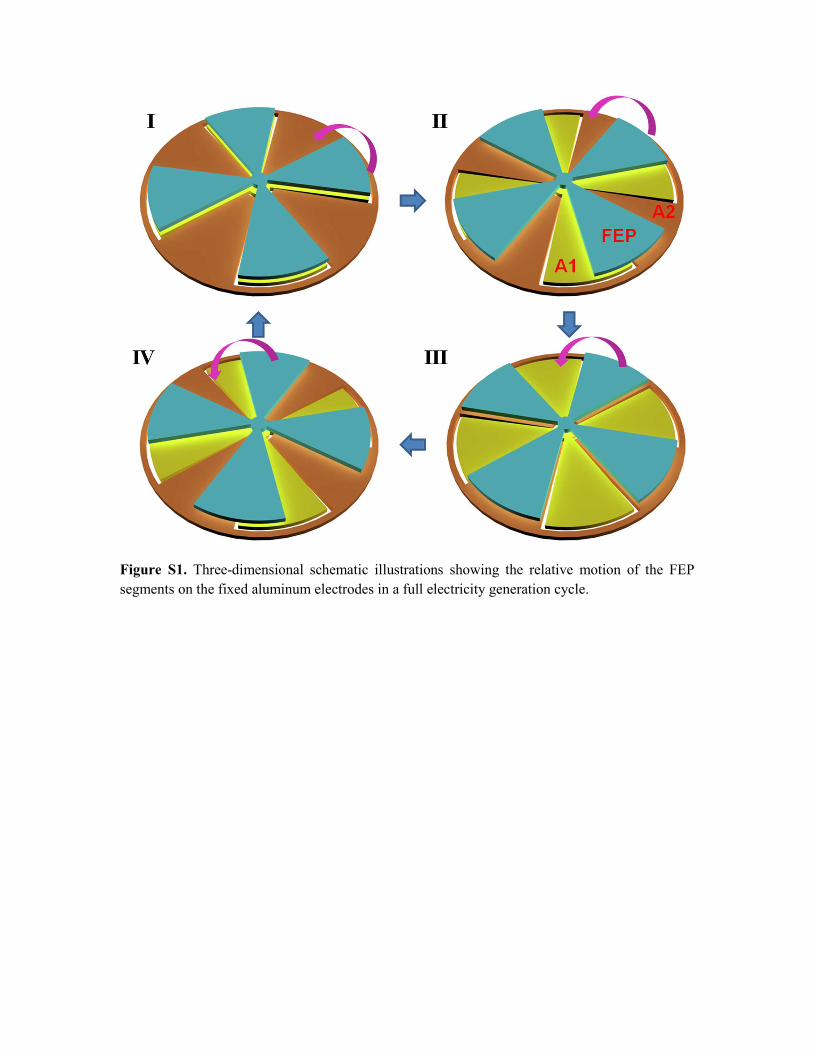
Figure S1. Three-dimensional schematic illustrations showing the relative motion of the FEP
segments on the fixed aluminum electrodes in a full electricity generation cycle.

Figure S2. The measured results of the QSC after continuous working of the FRD-TENG for
100,000, 200,000, and 500,000 cycles, respectively.
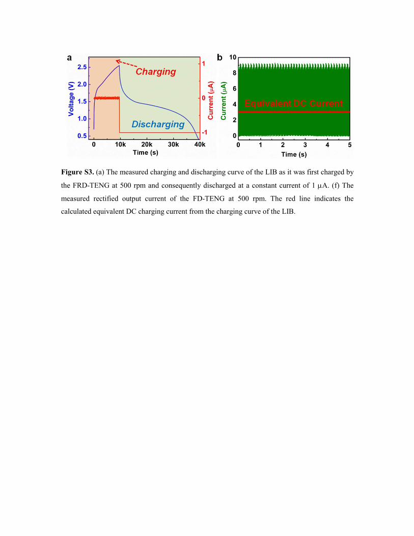
Figure S3. (a) The measured charging and discharging curve of the LIB as it was first charged by
the FRD-TENG at 500 rpm and consequently discharged at a constant current of 1 µA. (f) The
measured rectified output current of the FD-TENG at 500 rpm. The red line indicates the
calculated equivalent DC charging current from the charging curve of the LIB.
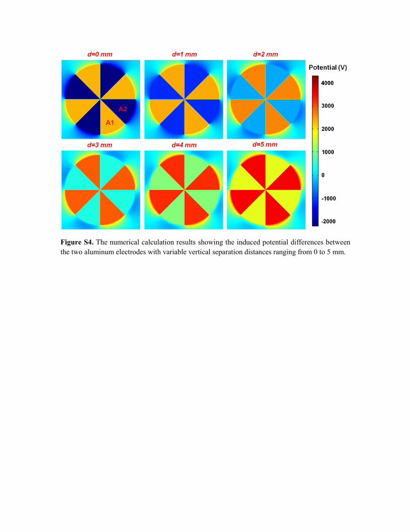
Figure S4. The numerical calculation results showing the induced potential differences between
the two aluminum electrodes with variable vertical separation distances ranging from 0 to 5 mm.
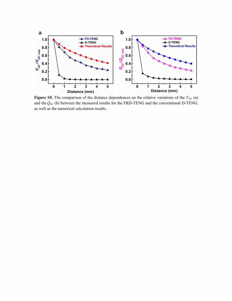
Figure S5. The comparison of the distance dependences on the relative variations of the VOC (a)
and the QSC (b) between the measured results for the FRD-TENG and the conventional D-TENG,
as well as the numerical calculation results.
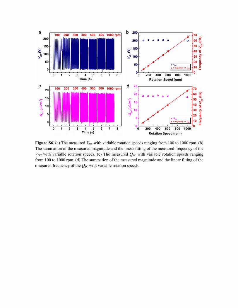
Figure S6. (a) The measured VOC with variable rotation speeds ranging from 100 to 1000 rpm. (b)
The summation of the measured magnitude and the linear fitting of the measured frequency of the
VOC with variable rotation speeds. (c) The measured QSC with variable rotation speeds ranging
from 100 to 1000 rpm. (d) The summation of the measured magnitude and the linear fitting of the
measured frequency of the QSC with variable rotation speeds.
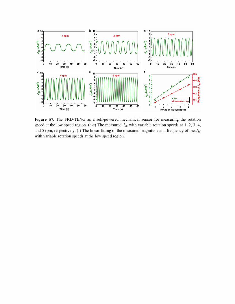
Figure S7. The FRD-TENG as a self-powered mechanical sensor for measuring the rotation
speed at the low speed region. (a-e) The measured JSC with variable rotation speeds at 1, 2, 3, 4,
and 5 rpm, respectively. (f) The linear fitting of the measured magnitude and frequency of the JSC
with variable rotation speeds at the low speed region.
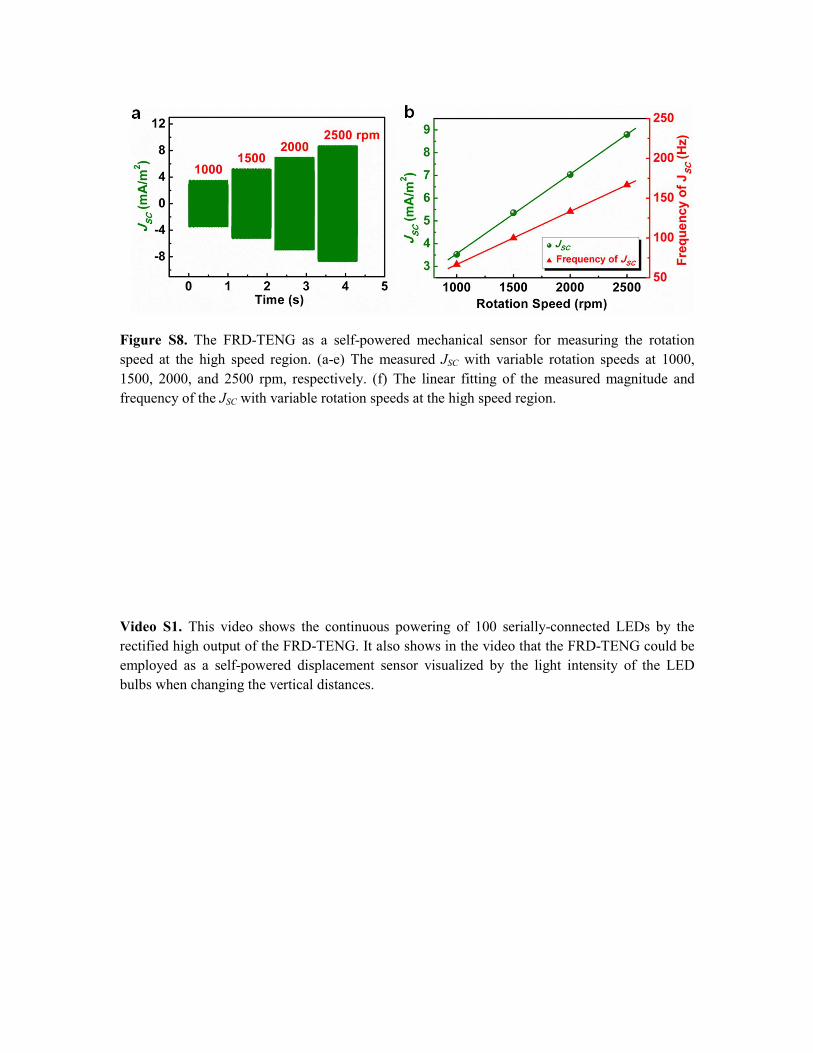
Figure S8. The FRD-TENG as a self-powered mechanical sensor for measuring the rotation
speed at the high speed region. (a-e) The measured JSC with variable rotation speeds at 1000,
1500, 2000, and 2500 rpm, respectively. (f) The linear fitting of the measured magnitude and
frequency of the JSC with variable rotation speeds at the high speed region.
Video S1. This video shows the continuous powering of 100 serially-connected LEDs by the
rectified high output of the FRD-TENG. It also shows in the video that the FRD-TENG could be
employed as a self-powered displacement sensor visualized by the light intensity of the LED
bulbs when changing the vertical distances.


![ALMA reveals a rotating [CII] disk in a gas rich galaxy at z = 4.76](https://static.fdocuments.in/doc/165x107/56815f0f550346895dcdce25/alma-reveals-a-rotating-cii-disk-in-a-gas-rich-galaxy-at-z-476.jpg)