Analysis of Steel Communication Towers in Iraq Under the ...
12
Eurasian Journal of Science & Engineering ISSN 2414-5629 (Print), ISSN 2414-5602 (Online) EAJSE Volume 5, Issue 1; December, 2019 36 Analysis of Steel Communication Towers in Iraq Under the Effect of Seismic Loading Mereen Hassan Fahmi Rasheed 1 & Faris Rashied Ahmed 2 Alameen Hamid Mohammed 3 1 Civil Engineering Department, Erbil Polytechnic University, Erbil, Iraq 2 Civil Engineering Department, Faculty of Engineering, Koya University, Erbil, Iraq 3 Civil Engineering Department, Faculty of Engineering, Tishk International University, Erbil, Iraq Correspondence: Alameen Hamid Mohammed, Tishk International University, Erbil, Iraq. Email: [email protected] doi: 10.23918/eajse.v5i1p36 Abstract: The telecommunication industry launched in Iraq two decades ago through three mobile network operators which are holding national licenses; Korek Telecom, Zain Iraq and Asiacell. Since the launch date till now, more than twelve thousand of telecommunication towers have been installed in Iraq holding and transmitting the telecommunication traffic between the Iraqi regions. However, this huge number of towers have been analyzed under the effects of wind loading only without taking into considerations the seismic effects with noting that there are many tremors which have been receded in the recent past. Accordingly, a specific type of towers with different heights have been selected and analyzed under the effects of seismic loading using both equivalent static and response spectrum methods and then the results were compared with the gained results from the wind analysis. After obtaining and analyzing the results, it could be used as a milestone for such a study for the coming telecommunication towers or the existing towers with different topologies and categories. Keywords: Bracings, Communication Towers, Response Spectrum Analysis, Seismic Analysis, Self- Supporting Towers 1. Introduction The growing demand for manufacturing and installing telecommunication towers has increased rapidly due to the high increase in the telecommunication business. The increase in the number of the towers leads to increasing the risk of such towers rapidly, therefore sufficient analysis for the environmental loading is highly required in order to avoid any hazardous impact which may result from these towers in case of failure. The telecommunication towers are fabricated from steel and constructed as trussed structures with different bracing patterns. They are constructed as tall steel frame construction to be used in handling the telecom and transmission equipment for telecommunication purposes. The demand for installing such a type of structure; especially in the absence of tall buildings is due to the facts that the steel towers are economical, lightweight and easy to fabricate and erect in comparison with any other types of structures. The telecommunication towers are categorized into three types which are self-supported towers, guyed towers and monopoles. The towers are also divided into two types, roof top towers and ground or green field towers based on their topology. They are also categorized based on the number of legs to four legs and three legs. The self-supported towers are generally preferable due to the smallest area required for implementation purposes, (Pathrikar & Kalurkar, 2017). The focus of this study will be on four
Transcript of Analysis of Steel Communication Towers in Iraq Under the ...

Eurasian Journal of Science & Engineering
ISSN 2414-5629 (Print), ISSN 2414-5602 (Online) EAJSE
Volume 5, Issue 1; December, 2019
36
Analysis of Steel Communication Towers in Iraq Under the Effect of
Seismic Loading
Mereen Hassan Fahmi Rasheed1 & Faris Rashied Ahmed2
Alameen Hamid Mohammed3
1 Civil Engineering Department, Erbil Polytechnic University, Erbil, Iraq 2 Civil Engineering Department, Faculty of Engineering, Koya University, Erbil, Iraq 3 Civil Engineering Department, Faculty of Engineering, Tishk International University, Erbil, Iraq
Correspondence: Alameen Hamid Mohammed, Tishk International University, Erbil, Iraq.
Email: [email protected]
doi: 10.23918/eajse.v5i1p36
Abstract: The telecommunication industry launched in Iraq two decades ago through three mobile
network operators which are holding national licenses; Korek Telecom, Zain Iraq and Asiacell. Since
the launch date till now, more than twelve thousand of telecommunication towers have been installed in
Iraq holding and transmitting the telecommunication traffic between the Iraqi regions. However, this
huge number of towers have been analyzed under the effects of wind loading only without taking into
considerations the seismic effects with noting that there are many tremors which have been receded in
the recent past. Accordingly, a specific type of towers with different heights have been selected and
analyzed under the effects of seismic loading using both equivalent static and response spectrum
methods and then the results were compared with the gained results from the wind analysis. After
obtaining and analyzing the results, it could be used as a milestone for such a study for the coming
telecommunication towers or the existing towers with different topologies and categories.
Keywords: Bracings, Communication Towers, Response Spectrum Analysis, Seismic Analysis, Self-
Supporting Towers
1. Introduction
The growing demand for manufacturing and installing telecommunication towers has increased
rapidly due to the high increase in the telecommunication business. The increase in the number of the
towers leads to increasing the risk of such towers rapidly, therefore sufficient analysis for the
environmental loading is highly required in order to avoid any hazardous impact which may result
from these towers in case of failure. The telecommunication towers are fabricated from steel and
constructed as trussed structures with different bracing patterns. They are constructed as tall steel
frame construction to be used in handling the telecom and transmission equipment for
telecommunication purposes. The demand for installing such a type of structure; especially in the
absence of tall buildings is due to the facts that the steel towers are economical, lightweight and easy
to fabricate and erect in comparison with any other types of structures. The telecommunication
towers are categorized into three types which are self-supported towers, guyed towers and
monopoles. The towers are also divided into two types, roof top towers and ground or green field
towers based on their topology. They are also categorized based on the number of legs to four legs
and three legs. The self-supported towers are generally preferable due to the smallest area required
for implementation purposes, (Pathrikar & Kalurkar, 2017). The focus of this study will be on four

Eurasian Journal of Science & Engineering
ISSN 2414-5629 (Print), ISSN 2414-5602 (Online) EAJSE
Volume 5, Issue 1; December, 2019
37
legged, green field and self-supporting towers with heights of 40, 60 and 80 m that have been listed
in table 1 as this type is the most common type of telecommunication towers in Iraq and the selected
heights are due to the fact that these towers are the most common towers that have been used in
carrying huge traffic, critical links and connecting many areas to each other thus these towers should
be fully functional during the hazards.
Table 1: Properties of the towers
Tower Height 40 m 60 m 80 m
Properties
Tower Type S.S. Tower S.S. Tower S.S. Tower
Number of Legs 4 – Legs 4 - Legs 4 - Legs
Tower Topology Green Field Green Field Green Field
Tower End Shape Straight End Straight End Straight
End
Bracings Straight Portion X X X
Slant Portion XBX XBX XBX
Heights
Height of slant portion 28m 48m 68m
Height of straight portion 12m 12m 12m
Bottom Dimensions Length 4.15m 7.04m 11.73m
Width 4.15m 7.04m 11.73m
Top Dimensions Length 1.5m 2m 2m
Width 1.5m 2m 2m
Number of Sections 22 17 11
The main reason for this study is due to the fact that none of the huge number of telecommunication
towers in Iraq has been analyzed under seismic loading or compared the seismic effects with the
wind effects while seismic activities in different Iraqi regions could obviously be seen. For that
reason, such a study is highly requested to be done to make sure that these towers will not be
affected by seismic actions and will not have an effect on people's lives or properties.
The design and drawings of existing towers are used in this study for modeling purpose after
checking them on ground to make sure that the mentioned dimensions are correct. The ETABS
17.0.1 software program, (Napier, 2014) has been used for the modeling and analysis purpose for the
three selected towers in this study with using ASCE7-16 code, (ASCE7-16, 2017) in the software
program. The local seismic parameters are not available in the ASCE code and should be extracted
from local codes therefore both Iraqi seismic code versions 2014 (Mijbil, Khalaf, Yousif, Rashied, &
Mahmood, 2014) and version 2017 (Mijbil, Khalaf, Yousif, Rashied, & Mahmood, 2017) have been

Eurasian Journal of Science & Engineering
ISSN 2414-5629 (Print), ISSN 2414-5602 (Online) EAJSE
Volume 5, Issue 1; December, 2019
38
used for this purpose.
2. Literature Review
Amiri, Massah, and Boostan (2007) studied the seismic response of 4-legged self-supported
telecommunication towers in Iran under the effects of the design spectrum from the Iranian seismic
code. The selected regions to gain the design spectrum values were Manjil, Tabas and Naghan. The
researchers selected ten different towers for this study. They found that the wind loads are the
dominant load compared with seismic load in general. They also observed that the weight of the
accessories has a great effect on the analysis results and should not be neglected. In addition, they
observed that the first three flexural modes were enough for analyzing these towers dynamically.
Another study has been done by Konno and Kimura (1973) on the effects of earthquake loads on the
lattice telecommunication towers and to obtain the mode shapes, natural frequencies and damping
properties of the selected towers and they found that the forces caused by earthquake were greater
than the observed forces from the wind loads in some members.
Gunathilaka, Lewanagamage, and Jayasinghe (2013) analyzed four-legged self-supported ground
towers with three heights 30 m, 50 m and 80 m in Sri Lanka under earthquake loading preceding the
other researchers in this field of study in Sri Lanka. The researchers used the equivalent static
method and ANSI/TIA-222-G-2005 code in their analysis. The selected towers have been designed
based on wind speeds of 180 km/h and 120 km/h as a recommended wind design speed in this
country. The researchers prepared a 3D model design for the analysis of the selected towers by using
SAP2000 software program. The values of Ss and S1 have been taken as 0.35 and 0.08 respectively
and site soil class has been taken C as the towers are constructed in hard soil. The support reactions,
maximum axial forces in leg member and maximum horizontal deflections of each tower with
respect to the load combination were obtained from this analysis. The results show that the axial
forces on leg members for 30 m tower under severe earthquake loads reached the design values
under wind speed of 120 km/h. but overall the study shows that the towers will survive under small
and reasonable seismic actions.
3. Methodology
The calculation of wind loading has been done for the comparison purpose with the results of the
seismic analysis as well as to make sure that these towers are withstanding the wind loading
according to their design. For that, the TIA-222-G code, (Telecommunication-Industry-Association,
2005) along with ASCE7-16 code, (ASCE7-16, 2017) have been used for extracting the required
parameters for completing the wind analysis for the three selected towers by ETABS software
program while the wind speed has been extracted from the technical specifications of the mobile
network operators; Korek Telecom, (Korek-Telecom, 2014) and Zain IQ, (ZAIN-IQ, 2007) as the
selected towers have been manufactured based on the specifications of these operators. The
solidarity ratio has been calculated manually after loading the towers with their full design
capacities. The wind load parameters that have been used for the analysis purpose are mentioned in
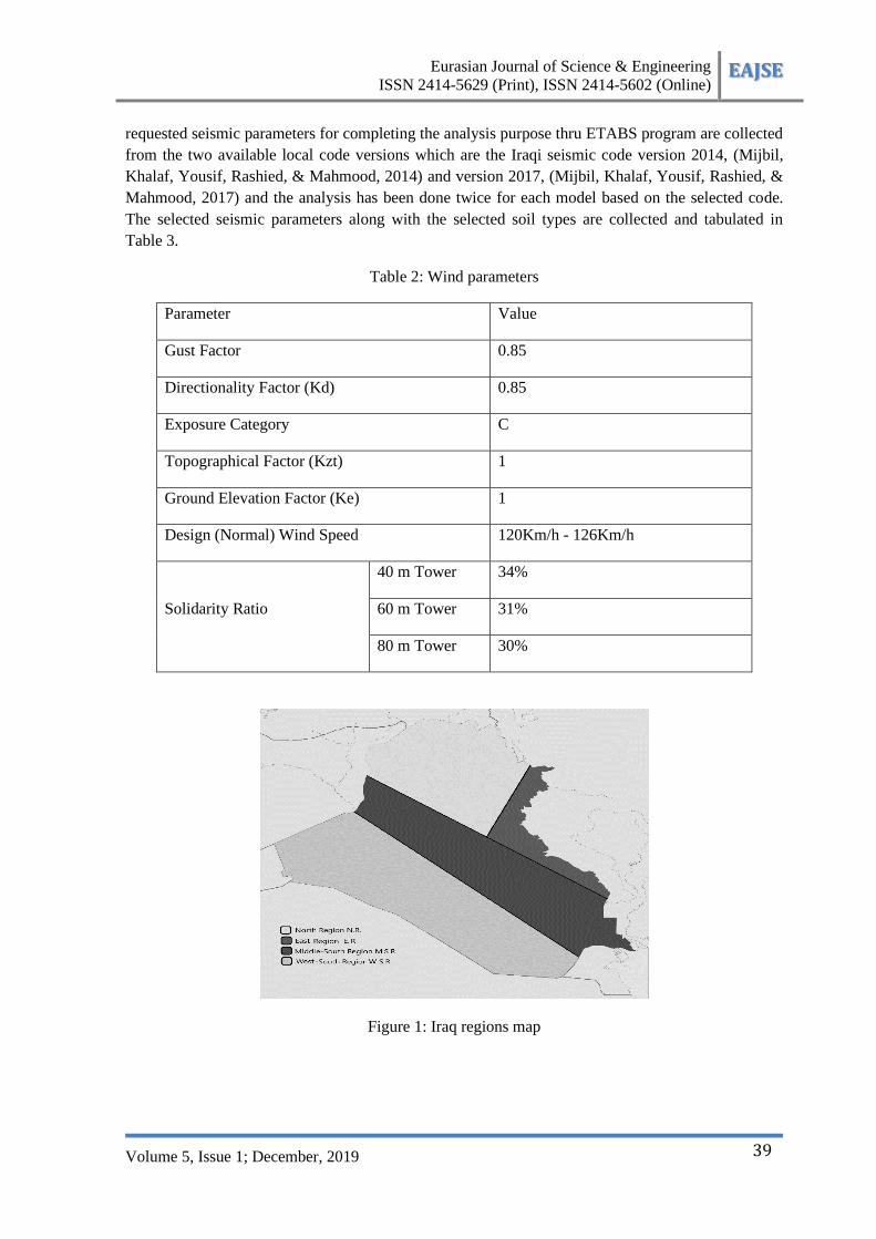
Table 2. As for the seismic analysis and in order to get more accurate results and due to the
variations in seismic parameters from region to region in Iraq, the country has been divided into four
regions as mentioned in Figure 1 below. The analysis for each one from the three selected towers for
this study has been performed in four selected regions which are shown in Figure 1 with taking into
considerations the soil types and selecting the weakest types till reaching the successful models. The
Eurasian Journal of Science & Engineering
ISSN 2414-5629 (Print), ISSN 2414-5602 (Online) EAJSE
Volume 5, Issue 1; December, 2019
39
requested seismic parameters for completing the analysis purpose thru ETABS program are collected
from the two available local code versions which are the Iraqi seismic code version 2014, (Mijbil,
Khalaf, Yousif, Rashied, & Mahmood, 2014) and version 2017, (Mijbil, Khalaf, Yousif, Rashied, &
Mahmood, 2017) and the analysis has been done twice for each model based on the selected code.
The selected seismic parameters along with the selected soil types are collected and tabulated in
Table 3.
Table 2: Wind parameters
Parameter Value
Gust Factor 0.85
Directionality Factor (Kd) 0.85
Exposure Category C
Topographical Factor (Kzt) 1
Ground Elevation Factor (Ke) 1
Design (Normal) Wind Speed 120Km/h - 126Km/h
Solidarity Ratio
40 m Tower 34%
60 m Tower 31%
80 m Tower 30%
Figure 1: Iraq regions map

Eurasian Journal of Science & Engineering
ISSN 2414-5629 (Print), ISSN 2414-5602 (Online) EAJSE
Volume 5, Issue 1; December, 2019
40
Table 3: Seismic parameters
Parameter Iraqi Code – 2014 Iraqi Code - 2017
Response modification factor
"R" 2 2
Over-strength factor "Ω" 1.5 1.5
Deflection amplification factor "
Cd" 1.5 1.5
Occupancy category IV IV
Occupancy importance factor " I
" 1.5 1.5
Spectral response acceleration
parameter at 0.2 second "Ss"
North (NR) 1.6 North (NR) 0.8
West (WR) 2.1 West (WR) 1
Middle-South
(MSR) 0.9
Middle-South
(MSR) 0.4
East-South
(ESR) 0.3 East-South (ESR) 0.2
Spectral response acceleration
parameter at 1 second "S1"
North (NR) 0.5 North (NR) 0.2
West (WR) 0.8 West (WR) 0.3
Middle-South
(MSR) 0.35
Middle-South
(MSR) 0.15
East-South
(ESR) 0.1 East-South (ESR) 0.05
Soil Classification
North (NR) C, D & E North (NR) D & E
East (ER) B, C, D &
E East (ER)
C, D &
E
Middle-South
(MSR) D & E
Middle-South
(MSR) E
West-South
(WSR) E
West-South
(WSR) E
The static analysis represented by the equivalent static method as well as the dynamic analysis
represented by the response spectrum method have been selected for the seismic analysis purpose.
The load combinations for the analysis purpose have been selected based on the ASCE7-16

Eurasian Journal of Science & Engineering
ISSN 2414-5629 (Print), ISSN 2414-5602 (Online) EAJSE
Volume 5, Issue 1; December, 2019
41
constrains to be as mentioned in Table 4.
Table 4: Selected load combinations
Load Case Case Name Safety Factors
1 DSTLD 1 Dead X 1 + Antenna X 1
2 DSTLS 1 Dead X 1.4+ Antenna X 1.4
3 DSTLS 2 Dead X 1.2 + Antenna X 1.2 + Wind X 1
4 DSTLS 3 Dead X 1.2 + Antenna X 1.2 + Wind X -1
5 DSTLS 4 Dead X 0.9 + Antenna X 0.9 + Wind X 1
6 DSTLS 5 Dead X 0.9 + Antenna X 0.9 + Wind X -1
7 DSTLS 6 Dead X 1.2 + Antenna X 1.2 + Ex X 1
8 DSTLS 7 Dead X 1.2 + Antenna X 1.2 + Ex X -1
9 DSTLS 8 Dead X 1.2 + Antenna X 1.2 + Ey X 1
10 DSTLS 9 Dead X 1.2 + Antenna X 1.2 + Ey X -1
11 DSTLS 10 Dead X 0.9 + Antenna X 0.9 + Ex X 1
12 DSTLS 11 Dead X 0.9 + Antenna X 0.9 + Ex X -1
13 DSTLS 12 Dead X 0.9 + Antenna X 0.9 + Ey X 1
14 DSTLS 13 Dead X 0.9 + Antenna X 0.9 + Ey X -1
15 DSTLS 14 Dead X 1.2 + Antenna X 1.2 + RS X 1
16 DSTLS 15 Dead X 0.9 + Antenna X 0.9 + RS X 1
4. Results and Discussion
The first coefficient that has been studied in this paper was the resulted base shear from the
equivalent and response spectrum seismic analysis for the three selected towers in all the mentioned
regions and selected soil types in the methodology and the results for the 40 m, 60 m and 80 m
towers have been shown in figures 2, 3 and 4 respectively.
From the figures it could be seen that the resulted base shear values are highest in the case of soil
type E considering same region and code version parameter for all the three types of the towers. The
results also show that the gained base shear from the seismic parameters of Iraqi code version 2014
are highest than the base shear values that were gained from seismic parameters of Iraqi code version
2017 for all the regions, soil types and in all the three selected towers. The resulted base shear values
also show that the east region always gives the highest values in comparing with the rest of the

Eurasian Journal of Science & Engineering
ISSN 2414-5629 (Print), ISSN 2414-5602 (Online) EAJSE
Volume 5, Issue 1; December, 2019
42
regions follows it the north region while the west-south region is always gives the lowest base shear
values.
This means further consideration should be taken in case if the Iraqi code version 2014 will be
selected for the design or analysis. In the case if the implemented tower is located in East or North
region more consideration should be taken. The soil type should also take into consideration as there
is a huge variation in the resulted base shear from type to type for the same region and same code
parameters.
Figure 2: Base shear values – 40 m tower
Figure 3: Base shear values – 60 m tower

Eurasian Journal of Science & Engineering
ISSN 2414-5629 (Print), ISSN 2414-5602 (Online) EAJSE
Volume 5, Issue 1; December, 2019
43
Figure 4: Base shear values – 80 m tower
The second studied coefficient was the maximum drift on the top of the three selected towers for this
study in the cases of wind, equivalent and response spectrum seismic analysis with comparing the
results with the allowable drift. The results for the 40 m, 60 m and 80 m towers in all the selected
regions and site soil types, with both code versions parameters have been shown in Figures 5, 6 and
7 respectively.
The resulted drift on the top of the selected towers shows that the allowable drift value is higher than
the obtained drift from all the wind analysis as well as all the selected cases for seismic analysis
which means that the selected towers are within the standard in the case of drift. The resulted drift
from the seismic loading in both static and dynamic methods exceeds the resulted drift from the wind
loading in many cases of study especially in the case of 40 m tower as in this tower the drift gained
from seismic loading exceeds the drift from wind loading in thirteen cases out of the sixteen selected
cases of study. The resulted drift due to seismic loading for the 60 m tower exceeds the resulted drift
from the wind loading in nine cases while in the case of 80 m tower it exceeds the resulted drift from
the wind loading in eight cases only out of the sixteen selected cases of study. The resulted drift due
to seismic loading are highest in the case of considering the Iraqi code version 2014 in comparison
with Iraqi code version 2017 that means more consideration should be taken in case of considering
the Iraqi code version 2014 in the design and analysis. The resulted drift due to seismic loading are
highest in the east region followed by the north region while the west-south region gives the lowest
drift values in all the soil type cases and for all the three selected towers that means more
consideration should be taken for the towers in the east and north regions. The soil type E gives the
highest drift values followed by the soil type D, thus more consideration should be taken in the case
of these two soil types.

Eurasian Journal of Science & Engineering
ISSN 2414-5629 (Print), ISSN 2414-5602 (Online) EAJSE
Volume 5, Issue 1; December, 2019
44
Figure 5: Maximum drift – 40 m tower
Figure 6: Maximum drift – 60 m tower
Figure 7: Maximum drift – 80 m tower
The last and the most important coefficient that has been studied is the overall pass and fail checking

Eurasian Journal of Science & Engineering
ISSN 2414-5629 (Print), ISSN 2414-5602 (Online) EAJSE
Volume 5, Issue 1; December, 2019
45
for the tower members under the effects of wind and seismic loading. The results of the checking
under the effects of wind loading based on the selected wind parameters that have been mentioned in
the methodology show that all the three selected towers are withstanding the wind loads without a
single case of failure.
The pass and fail checking under the seismic loading held based on the selected seismic parameters
from both local code versions and site soil classes C, D and E. The results for the three selected
towers are tabulated in Table 5.
Table 5: Pass and fail results under the seismic effects
Region Code
Version
Soil Type - C Soil Type - D Soil Type - E
40 m 60 m 80 m 40 m 60 m 80 m 40 m 60 m 80 m
North
201
4
Pass Pass Pass Pass Pass 24 16 136 96
East 8 48 Pass 32 8 72 48 222 168
Mid - South Pass Pass Pass Pass Pass Pass Pass 32 8
West - South Pass Pass Pass Pass Pass Pass Pass Pass Pass
North
2017
Pass Pass Pass Pass Pass Pass Pass 16 Pass
East Pass Pass Pass Pass Pass Pass Pass 32 Pass
Mid - South Pass Pass Pass Pass Pass Pass Pass Pass Pass
West - South Pass Pass Pass Pass Pass Pass Pass Pass Pass
The results in Table 5 show that there are many fail cases in tower members in the three selected
towers especially when selecting the code version 2014 therefore higher consideration should be
taken in case of selecting this code in the design or analysis of the telecommunication towers. The
soil type has a great effect on the results as the failure in towers members in case of soil type E are
much higher than the rest of soil types, while the soil type C acts much better than soil type D in
regard to the number of failed members; therefore the soil type should be considered in designing
and analyzing process. The region also has a huge effect on the results as the towers in west-south
region acts much better than the towers in the rest of the regions, while the towers that located in east
acts worst that the rest followed by the north region; therefore the region of installation should be
considered in designing and analyzing process.
5. Conclusion and Recommendations
5.1 Conclusion
From the gained results the following points could be concluded:
The three selected towers withstand the wind loading without requesting any modification in their
designs. The resulted drift from the seismic loading in many cases especially in the north and east
regions are more than the resulted drift from the wind loading. This means that the effects of seismic

Eurasian Journal of Science & Engineering
ISSN 2414-5629 (Print), ISSN 2414-5602 (Online) EAJSE
Volume 5, Issue 1; December, 2019
46
should be taken into consideration when designing and analyzing the telecommunication towers.
There are many cases of failure in the tower members in all three selected towers under the effects of
seismic loading by taking into consideration that the same towers passed under the effects of wind
loading. This means that it is a must to take the seismic loading into consideration when designing or
analyzing the telecommunication towers in the country of study.
The study expresses four cases of failure in the 40 m and 80 m tower and six cases of failure in the
60 m tower under the effect of seismic loading out of the nine cases that have been considered for the
seismic parameters of the Iraqi seismic code version 2014. The failure concentrated in north and east
regions with one case of failure only in the middle-south region related to 60 m and 80 m tower in
the case of soil type E. This means that if this code has been considered, a huge consideration should
be taken in designing the towers especially in the east region first then in the north region. In the case
of using the seismic parameters of Iraqi seismic code version 2017, it seems that there are only two
cases of failure in the 60 m tower in the north and east regions in the case of soil type E. This means
a treatment for 60 m tower need to be done only in the case if the tower installed in soil type E and in
east or north region.
5.2 Recommendations
From the study, the following points are recommended:
Working on credence one local code for the seismic effects with logical seismic parameters is
recommended for the future work. The telecommunication industry has no limitations therefore there
will be new sites to be added to expand the telecommunication network and new towers will be
manufactured. For the new manufactured towers, the seismic analysis should be considered. In order
to avoid the extra cost for manufacturing the new towers with bigger member sizes due to seismic
loading in all of Iraqi regions, the manufacturing could be done based on the region of installation as
what happen in this study due to variations in the seismic parameters from region to region.
Additional studies to be held on the remaining types of the towers that have been installed in Iraq
considering the effects of seismic loading as this paper does not cover all the tower types and
topologies in the selected country of study.
References
Amiri, G. G., Massah, S. R., & Boostan, A. (2007). Seismic response of 4-legged self-supporting
telecommunication towers. Archive of SIDIJE Transactions B: Applications, 107-126.
ASCE7-16. (2017). Minimum Design Loads and Associated Criteria for Buildings and Other
Structures "ASCE7-16". Reston, Virginia: American Society of Civil Engineers.
Gunathilaka, A., Lewanagamage, C., & Jayasinghe, M. (2013). Analysis and design of
telecommunication towers for earthquake loading in Sri Lanka for sustainability. Digital
library, University of Moratuwa Sri-Lanka.
Konno, T., & Kimura, E. (1973). Earthquake effects on steel tower structures atop buildings. World
Conference on Earthquake Engineering (pp. 184-193). Rome, Italy: the 5th World
Conference on Earthquake Engineering.
Korek-Telecom. (2014). Site Technical Specifications New Site Construction & Deployment. Erbil:
Korek Telecom.
Mijbil, D. A., Khalaf, D. H., Yousif, D. M., Rashied, D. M., & Mahmood, D. A. (2014). Iraqi
Seismic code version 2014. Baghdad.
Mijbil, D. A., Khalaf, D. H., Yousif, D. M., Rashied, D. M., & Mahmood, D. A. (2017). Iraqi
Seismic code version 2017. Baghdad.

Eurasian Journal of Science & Engineering
ISSN 2414-5629 (Print), ISSN 2414-5602 (Online) EAJSE
Volume 5, Issue 1; December, 2019
47
Napier, R. (2014). CSI Knowledge Base. Retrieved from Ritz vs. Eigen vector:
https://wiki.csiamerica.com/display/kb/Ritz+vs.+Eigen+vectors
Pathrikar, A., & Kalurkar, P. (2017). Analysis of telecommunication tower with different bracing
system. IOSR Journal of Mechanical and Civil Engineering (IOSR-JMCE), 59-64.
Telecommunication-Industry-Association. (2005). Structural Standard for Antenna Supporting
Structures and Antennas "TIA-222-G". USA, Arlington: Telecommunication Industry
Association.
ZAIN-IQ. (2007). BTS & Transmission Sites Self-Supporting (SS) Lattice Tower Specification ZAI-
ENG-BTS-FSP-108 Version 2. Baghdad: ZAIN IQ.