ANALYSIS OF ROTARY SWAGING TOOLING ROLLING · analysis of rotary swaging tooling rolling contact...
4
ANALYSIS OF ROTARY SWAGING TOOLING ROLLING CONTACT FATIGUE AND LIFE IMPROVEMENT UNDER SERVICE CONDITIONS H. LIN, J. PILLAR, M. DEIS, D. COMBS Dana Corporation, Advanced Technology Resource Group, 8000 Yankee Road, Ottawa Lake, Michigan 49267, USA; e-mail: [email protected] D. RHODA, D. BEITZEL, T. SELFE Spicer Driveshaft, Inc., 6201 Trust Drive, Holland, Ohio 43528, USA SUMMARY Rotary swaging tooling rolling contact fatigue under operating conditions was investigated. First, rotary swaging tooling service conditions were identified in terms of load, speed, temperature, and lubrication. Secondly, analysis was conducted to characterize tooling materials and tooling contact fatigue mechanisms. Thirdly, computation was carried out to determine the load capacity of the rotary swaging machine, tooling dynamic load rating, tooling rolling contact fatigue life, Hertz contact stress and elasto hydrodynamic lubrication (EHL) analysis for oil film thickness. Finally tooling life improvement technologies were explored and discussed. Based on the results of experimental and computational work, typical tooling rolling contact fatigue and wear mechanism was determined, which consisted of surface brinelling, surface pitting, and crack growth. The primary cause for the rolling contact fatigue of tooling was contamination of the lubrication from swaging debris. Periodic overload and high contact stress also contributed to the tooling contact fatigue. Keywords: rotary swaging tooling, rolling contact fatigue 1 INTRODUCTION Rotary swaging is a process for reducing the cross sectional area of bars and tubes by repeated radial impact with dies, hammers and rollers. The main advantages of the process are manufacturing efficiency and flexibility, reduced part weight, reduced loss of work material, and improved overall productivity. Besides the capital cost of a rotary swaging machine, tooling is also a major cost of the process. As a result it is important to analyse the tooling wear mechanism and improve tooling life with the aim of continuously improving productivity and reducing waste. Fig.1. A schematic diagram of a rotary swaging machine. Fig. 1 shows a schematic diagram of a typical high load capacity rotary swaging machine which consists of one outer ring, one cage, 12 rollers, four spacers, four hammers and four dies, besides other accessories. The four die-sets oscillate in the radial direction as rollers pass over hammers, which creates high frequency radial blows and reduces part diameter by material flow. There are several contact points among various tooling, such as contact between rollers and the outer ring, contact between dies and the part, contacts between rollers and hammers, and contact between rollers and cage. However, only the contact between hammers and rollers are non conformal contacts, which results in highest contact stress and lowest oil film thickness. As a result, hammers and rollers normally lose surface integrity earlier than other tooling. The swaging machine manufacturer has suggested that normal tooling life is about 100 million revolutions. However, during actual operation, pitting or contact fatigue appears on hammers and rollers after about 3 million revolutions, which is only about 3% of the normal tooling life suggested by the machine manufacturer. The only thing new with the current rotary swaging operation is that non-ferrous metal parts rather than steel parts are swaged. This difference in swaging part material did not get full attention of the swaging machine manufacturer at the machine design and manufacturing stage because the non-ferrous metal was assumed to be easier to swage than steel due to its lower strength. However, machine operators had observed severe lubricant contamination during swaging operation because of significant amount of debris, which was identified as a potential problem. Lubricant contami- nation turned out to be the root cause of premature pitting of the tooling as explained in the following sections.
Transcript of ANALYSIS OF ROTARY SWAGING TOOLING ROLLING · analysis of rotary swaging tooling rolling contact...

ANALYSIS OF ROTARY SWAGING TOOLING ROLLING CONTACT FATIGUE AND LIFE IMPROVEMENT UNDER SERVICE CONDITIONS H. LIN, J. PILLAR, M. DEIS, D. COMBS Dana Corporation, Advanced Technology Resource Group, 8000 Yankee Road, Ottawa Lake, Michigan 49267, USA; e-mail: [email protected] D. RHODA, D. BEITZEL, T. SELFE Spicer Driveshaft, Inc., 6201 Trust Drive, Holland, Ohio 43528, USA SUMMARY Rotary swaging tooling rolling contact fatigue under operating conditions was investigated. First, rotary swaging tooling service conditions were identified in terms of load, speed, temperature, and lubrication. Secondly, analysis was conducted to characterize tooling materials and tooling contact fatigue mechanisms. Thirdly, computation was carried out to determine the load capacity of the rotary swaging machine, tooling dynamic load rating, tooling rolling contact fatigue life, Hertz contact stress and elasto hydrodynamic lubrication (EHL) analysis for oil film thickness. Finally tooling life improvement technologies were explored and discussed. Based on the results of experimental and computational work, typical tooling rolling contact fatigue and wear mechanism was determined, which consisted of surface brinelling, surface pitting, and crack growth. The primary cause for the rolling contact fatigue of tooling was contamination of the lubrication from swaging debris. Periodic overload and high contact stress also contributed to the tooling contact fatigue.
Keywords: rotary swaging tooling, rolling contact fatigue
1 INTRODUCTION Rotary swaging is a process for reducing the cross sectional area of bars and tubes by repeated radial impact with dies, hammers and rollers. The main advantages of the process are manufacturing efficiency and flexibility, reduced part weight, reduced loss of work material, and improved overall productivity. Besides the capital cost of a rotary swaging machine, tooling is also a major cost of the process. As a result it is important to analyse the tooling wear mechanism and improve tooling life with the aim of continuously improving productivity and reducing waste.
Fig.1. A schematic diagram of a rotary swaging
machine.
Fig. 1 shows a schematic diagram of a typical high load capacity rotary swaging machine which consists of one outer ring, one cage, 12 rollers, four spacers, four
hammers and four dies, besides other accessories. The four die-sets oscillate in the radial direction as rollers pass over hammers, which creates high frequency radial blows and reduces part diameter by material flow. There are several contact points among various tooling, such as contact between rollers and the outer ring, contact between dies and the part, contacts between rollers and hammers, and contact between rollers and cage. However, only the contact between hammers and rollers are non conformal contacts, which results in highest contact stress and lowest oil film thickness. As a result, hammers and rollers normally lose surface integrity earlier than other tooling.
The swaging machine manufacturer has suggested that normal tooling life is about 100 million revolutions. However, during actual operation, pitting or contact fatigue appears on hammers and rollers after about 3 million revolutions, which is only about 3% of the normal tooling life suggested by the machine manufacturer. The only thing new with the current rotary swaging operation is that non-ferrous metal parts rather than steel parts are swaged. This difference in swaging part material did not get full attention of the swaging machine manufacturer at the machine design and manufacturing stage because the non-ferrous metal was assumed to be easier to swage than steel due to its lower strength.
However, machine operators had observed severe lubricant contamination during swaging operation because of significant amount of debris, which was identified as a potential problem. Lubricant contami-nation turned out to be the root cause of premature pitting of the tooling as explained in the following sections.
In order to identify and confirm the root cause of the premature tooling pitting and thus improve tooling life, both analysis and calculations were carried out in this work. Tooling material and surface roughness, tooling contact fatigue mechanism, radial load capacity of the swaging machine, tooling contact fatigue life, and lubrication/contamination are the main subjects of investigation. 2 ROTARY SWAGING TOOLING STEELS
AND OPERATING CONDITIONS Tooling is made of either a high speed tool steel or a high carbon low alloy steel with major alloying elements of Chromium, Molybdenum, Tungsten, Vanadium, Cobalt and Nickel. These tooling steels offer the advantages of uniform microstructure, good balance of toughness and wear resistance, and good machinability.
Tooling is normally through hardened to 60-62 HRc. Hammer and roller contact zone length is 150 mm. Hammer contact radius is 50 mm, and the diameter of the roller is 70 mm. Surface roughness of a hammer and a roller with severe surface pitting were measured using a stylus profilometer on the area away from the pits. Both hammer and roller have a surface roughness of Ra = 0.1 micron (4 micro inch) and Rq = 0.15 micron (6 micro inch) along the rolling direction (Rq is defined as the root mean square roughness).
It must be noted here that these roughness values are significantly lower than the surface roughness specifications of the tooling because the hammer and the roller were broken in and polished during swaging operation.
The operating conditions for the hammers and rollers are as follows: hammer surface speed is about 500 cm/second, hammer and roller contact is under almost pure rolling condition. The normal radial load is 45,455 kg (100,000 lbs.), the lubricant tank temperature is normally at 70 degree C. The lubricant is a light-body and light colour oil designed for high speed machine tools with the following properties: Gravity: API 36.1, Viscosity: 10 cSt at 40 C, 2.6 cSt at 100 C, and viscosity index: 95. The swaging part material has yield strength of 140 MPa and tensile strength of 220 MPa.
The main function of the swaging lubricant is to carry out the swaging debris and to transport heat away from contact zone. Swaging operation requires friction between dies and the part. However, tooling surface integrity and durability requires low friction and oil film in the contact zone of tooling. This makes the selection of a swaging lubricant a very challenging task.
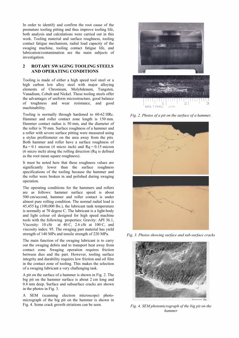
A pit on the surface of a hammer is shown in Fig. 2. The big pit on the hammer surface is about 2 cm long and 0.8 mm deep. Surface and subsurface cracks are shown in the photos in Fig. 3.
A SEM (scanning electron microscope) photo-micrograph of the big pit on the hammer is shown in Fig. 4. Some crack growth striations can be seen.
Fig. 2. Photos of a pit on the surface of a hammer.
Fig. 3. Photos showing surface and sub-surface cracks
Fig. 4. SEM photomicrograph of the big pit on the
hammer

Hardness and microstructure of the hammer and the roller were evaluated. The hardness results are within specifications and the microstructure appears normal. Fig. 5 shows the microstructure of the hammer with the big pit at 0.5 mm below surface. Chemistry and surface roughness of the hammer and the roller were also evaluated, and they are also within the design specifications.
Fig. 5. Photomicrograph of the hammer, 0.5 mm below
surface (1000X)
3 ANALYTICAL EVALUATION RESULTS From the material and surface analysis results of the hammer and the roller, it was concluded that tooling materials and manufacturing process were not the root cause of contact fatigue. Therefore, the focus of this section is on the load and lubrication conditions. Load capacity of the swaging machine, Hertz contact stress calculation, and elasto hydrodynamic lubrication calculations for the hammer and roller contact were conducted.
The radial load between the hammer and the roller depends on the diameter of the part being swaged, the die contact length, and the flow strength of the part material. However, during a swaging operation, part diameter decreases, and flow strength increases continuously, contact length between die and part also changes. Therefore it is rather difficult to calculate the radial load. An approximate method of estimating the radial load has been suggested in [1]:
Radial Load = Part Diameter x Die Length x Strength
With this formulae, the maximum load during a swaging operation is estimated to be 86400 kg, based on part diameter of 6 cm, die length of 8 cm and strength of 180 MPa, Here strength =180 MPa is the average of yield strength and tensile strength of the part material. Compared with the designed load of 45455 kg, one can conclude that the rotary swaging machine can be overloaded during normal operation.
The basic dynamic loading rating for the swaging tooling may be calculated based on the method given in [2]. The dynamic load rating is defined as the load under which 90% of a group of apparently identical roller bearings will survive a million revolutions of rolling contact fatigue (RCF) life.
Cr = bm fc (I L cosα) 7/9 Z 3/4 D 29/27 (1) Where Cr: dynamic load rating bm: rating factor, 1.1 for cylindrical rollers fc: factor (materials, geometry, manufacturing), fc = 88 when D cosα / d = 0.22 L: roller effective length, L = 146 mm, D: roller diameter, D = 69 mm, I: number of rows, I = 1, Z: number of rollers per row, Z = 12, d = 318 mm, d is the bearing pitch diameter
Substitute these data into Eqn. (1), one gets Cr = 2.84E6 newtons = 284,000 kg
Then tooling RCF fatigue life can be calculated based on: L = a1 a2 a3 ( Cr / P ) 3.33 (2) Where a1: reliability factor, a1 = 1 for 90%, 0.62 for 95%, 0.21 for 99% reliability a2: materials factor, a2 = 1 for acceptable steel, heat treatment and manufacturing a3: operating factor, it depends on lubrication and contamination, a3 = 1 when λ equals to or larger than 1, λ is the ratio of lubricant film thickness in the contacts to the composite root mean square roughness of the contact surfaces Cr: dynamic load rating, Cr = 284,000 kg P: actual dynamic load
Using Eqn. (2), and assuming normal material and operating conditions, i.e. a1 = a2 = a3 = 1, one can relate radial load P with tooling RCF life, as shown in Table 1 below:
Cr / P Actual Load P (Kg)
RCF Life (Revolutions in million)
1 284,000 1 1.4 200,000 3 3.28 86400 52 4 71000 100 6.2 45455 446 Table 1. RCF Life under normal conditions and 90%
reliability, a1 =a2 =a3=1
Examining the results in Table 1, one can see that the designed load 45455 kg under normal conditions will give a predicted RCF life of 446 million revolutions which is well beyond the designed life of 100 million revolutions suggested by the swaging machine manufacturer. The lowest actual tooling life is only 3 million revolutions which correspond to 200,000 kg load, much higher than the estimated machine load capacity 86400 kg. This overload condition is too high to be real. Something else must have contributed to the pitting of tooling. Now if one assumes 99% reliability, i.e. a1 = 0.21, and normal materials and manufacturing quality a2 = 1, but poor lubrication condition a3 = 0.2, then another load vs. RCF life table can be generated using Eqn. (2):
Cr / P Actual Load P (Kg)
RCF Life (Revolutions in million)
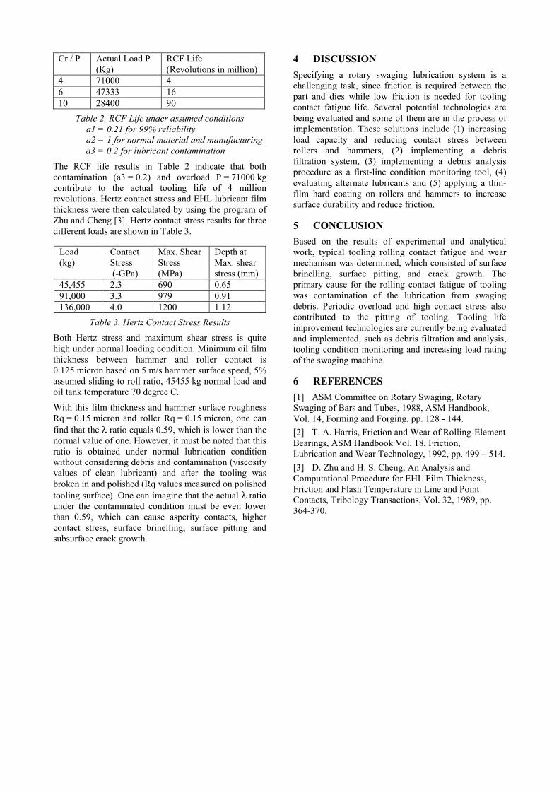
4 71000 4 6 47333 16 10 28400 90
Table 2. RCF Life under assumed conditions a1 = 0.21 for 99% reliability a2 = 1 for normal material and manufacturing a3 = 0.2 for lubricant contamination
The RCF life results in Table 2 indicate that both contamination (a3 = 0.2) and overload P = 71000 kg contribute to the actual tooling life of 4 million revolutions. Hertz contact stress and EHL lubricant film thickness were then calculated by using the program of Zhu and Cheng [3]. Hertz contact stress results for three different loads are shown in Table 3.
Load (kg)
Contact Stress (-GPa)
Max. Shear Stress (MPa)
Depth at Max. shear stress (mm)
45,455 2.3 690 0.65 91,000 3.3 979 0.91 136,000 4.0 1200 1.12
Table 3. Hertz Contact Stress Results Both Hertz stress and maximum shear stress is quite high under normal loading condition. Minimum oil film thickness between hammer and roller contact is 0.125 micron based on 5 m/s hammer surface speed, 5% assumed sliding to roll ratio, 45455 kg normal load and oil tank temperature 70 degree C.
With this film thickness and hammer surface roughness Rq = 0.15 micron and roller Rq = 0.15 micron, one can find that the λ ratio equals 0.59, which is lower than the normal value of one. However, it must be noted that this ratio is obtained under normal lubrication condition without considering debris and contamination (viscosity values of clean lubricant) and after the tooling was broken in and polished (Rq values measured on polished tooling surface). One can imagine that the actual λ ratio under the contaminated condition must be even lower than 0.59, which can cause asperity contacts, higher contact stress, surface brinelling, surface pitting and subsurface crack growth.
4 DISCUSSION Specifying a rotary swaging lubrication system is a challenging task, since friction is required between the part and dies while low friction is needed for tooling contact fatigue life. Several potential technologies are being evaluated and some of them are in the process of implementation. These solutions include (1) increasing load capacity and reducing contact stress between rollers and hammers, (2) implementing a debris filtration system, (3) implementing a debris analysis procedure as a first-line condition monitoring tool, (4) evaluating alternate lubricants and (5) applying a thin-film hard coating on rollers and hammers to increase surface durability and reduce friction. 5 CONCLUSION Based on the results of experimental and analytical work, typical tooling rolling contact fatigue and wear mechanism was determined, which consisted of surface brinelling, surface pitting, and crack growth. The primary cause for the rolling contact fatigue of tooling was contamination of the lubrication from swaging debris. Periodic overload and high contact stress also contributed to the pitting of tooling. Tooling life improvement technologies are currently being evaluated and implemented, such as debris filtration and analysis, tooling condition monitoring and increasing load rating of the swaging machine. 6 REFERENCES [1] ASM Committee on Rotary Swaging, Rotary Swaging of Bars and Tubes, 1988, ASM Handbook, Vol. 14, Forming and Forging, pp. 128 - 144. [2] T. A. Harris, Friction and Wear of Rolling-Element Bearings, ASM Handbook Vol. 18, Friction, Lubrication and Wear Technology, 1992, pp. 499 – 514. [3] D. Zhu and H. S. Cheng, An Analysis and Computational Procedure for EHL Film Thickness, Friction and Flash Temperature in Line and Point Contacts, Tribology Transactions, Vol. 32, 1989, pp. 364-370.